

Page 1
Ref. 564901
www.televes.com
ES
Procesador A/D TWIN
TWIN A/D PROCESSOR
Guía rápida
Quick guide
EN
Page 2

Page 3
8
(*)
Fig. 1
Fig. 2
UCC-T
A
B
C
PR
G
M
PROCESSOR TWIN
UCC-T
PROCESSOR TWIN
UCC-T
PROCESSOR TWIN
UCC-T
PROCESSOR TWIN
UCC-T
PRGM
PROCESSOR TWIN
UCC-T
PRGM
PROCESSOR TWIN
BROADBAND AMPLIFIER
TEST
(-30dB)
UAMP44
1
2
CLAC!
7234
4061
5071
5239
564901
5629
5575
RF
RF
UCC-T
CTRL
PRGM
PROCESSOR TWIN
PWR
6
7
8
5
1
3
2
4
Page 4
PROCESADOR A/D TWIN
4
Importantes instrucciones de seguridad
Condiciones generales de instalación
• Antes de manipular o conectar el equipo leer éste manual.
• Para reducir el riesgo de fuego o choque eléctrico, no exponer el equipo a la
lluvia o a la humedad.
• No quitar la tapa del equipo sin desconectarlo de la alimentación.
• No obstruir las ranuras de ventilación del equipo.
• Deje un espacio libre alrededor del aparato para proporcionar una ventilación
adecuada.
• El aparato no debe ser expuesto a caídas o salpicaduras de agua. No situar
objetos o recipientes llenos de agua sobre o cerca del aparato si no se tiene la
su ciente protección.
• No situar el equipo cerca de fuentes de calor o en ambientes de humedad
elevada.
• No situar el equipo donde pueda estar sometido a fuertes vibraciones o sacudidas.
• Este símbolo indica que el equipo cumple los requerimientos del
marcado CE.
Descripción Entradas / Salidas / Conexiones
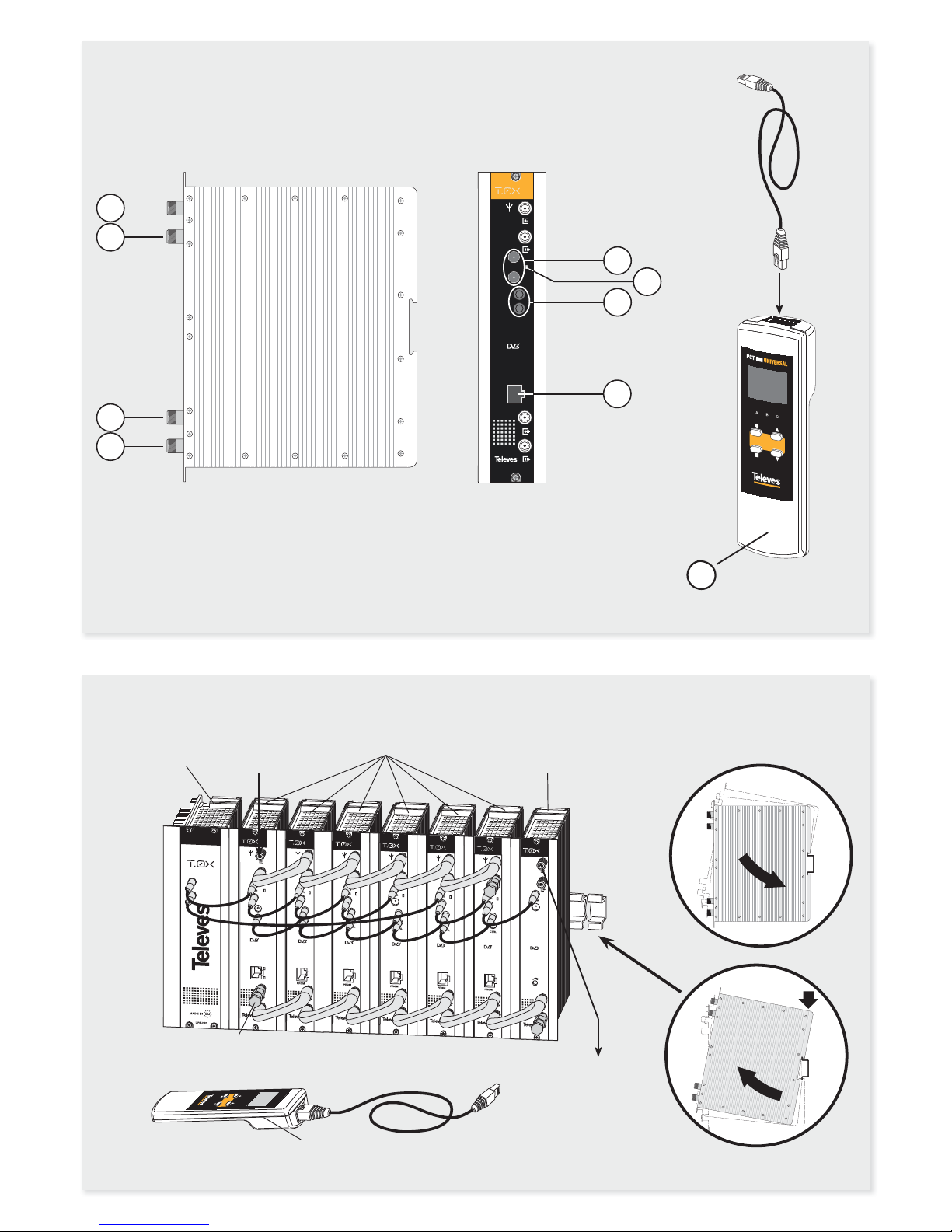
El módulo (Fig. 1) dispone de:
1. Entrada RF (12V/24V/O )
2. Salida RF (lazo señal de entrada)
3. Entrada RF (lazo señal de salida)
4. Salida RF
5. Conectores BUS de alimentación
6. LED de estado
7. Conectores BUS de control
8. Conector programador / PC
Introducción
El Procesador permite seleccionar cualquier canal en la banda de VHF o UHF
(46-862 MHz) y colocardo igualmente en cualquier posición dentro de dichas
bandas.
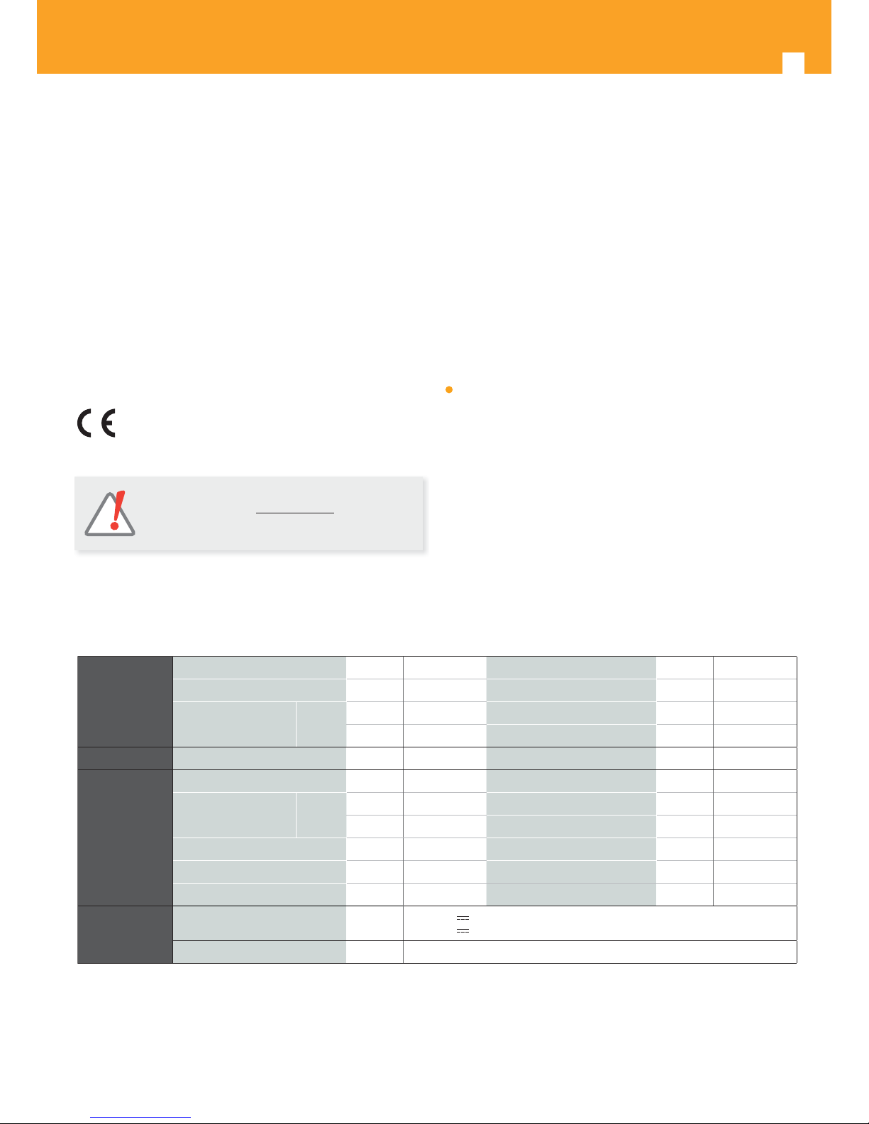
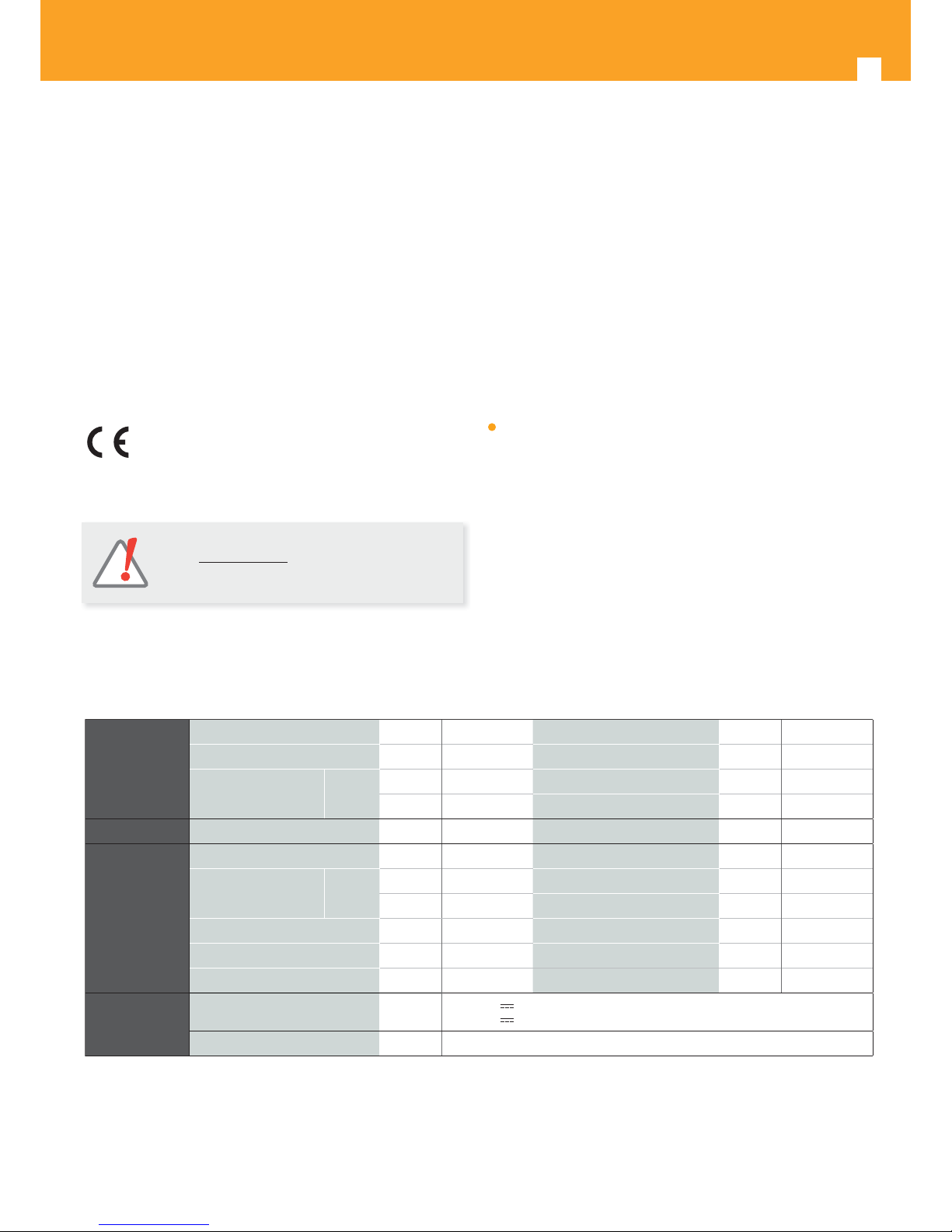
Características técnicas
NOTA: Dispone de un Manual de Instrucciones completo
en nuestra web: www.televes.com.
Enlaces disponibles al nal de esta guía.
Down-Converter
Frecuencia de entrada (selec.) MHz 46 - 862 Conectores de entrada/salida tipo “F” hembra
Nivel de entrada dBμV 50 a 80* Impedancia de entrada ohm. 75
Pasos de frecuencia
(selec.)
KHz
Analógico 250 Alimentación Previos (< 50 mA) V 12 / 24 / OFF
Digital 166,66 / 125 Lazo entrada dB 0 ± 3
F.I. Ancho de banda (selec.) MHz 6 / 7 / 8
UP-Converter
Frecuencia de salida (selec.) MHz 46 - 862 Pérdidas de paso (tip) dB < 1,5
Pasos de frecuencia
(selec.)
KHz
Analógico 250 Pérdidas de retorno (tip) dB > 12
Digital 166,66 / 125 Conectores de entrada/salida tipo “F” hembra
Ruído de fase (tip) dBc/Hz 80 @10KHz Impedancia de salida ohm. 75
Nivel de salida dBμV 80 ±5 Nivel de espúreos (min) dBc 60
Nivel de salida ajustable dB > 15 Regulación de pendiente dB ±3
General
Consumo (tip.) mA
400 @ 24V (sin alimentación a previos)
450 @ 24V
(con alimentación a previos)
Indice de Protección IP20
* Autorregulación de la ganancia para niveles elevados de la señal de entrada.
Las características técnicas descritas se de nen para una temperatura ambiente máxima de 45°C (113ºF). Para temperaturas superiore s se utilizará ventilación forzada.
Page 5
ES
5
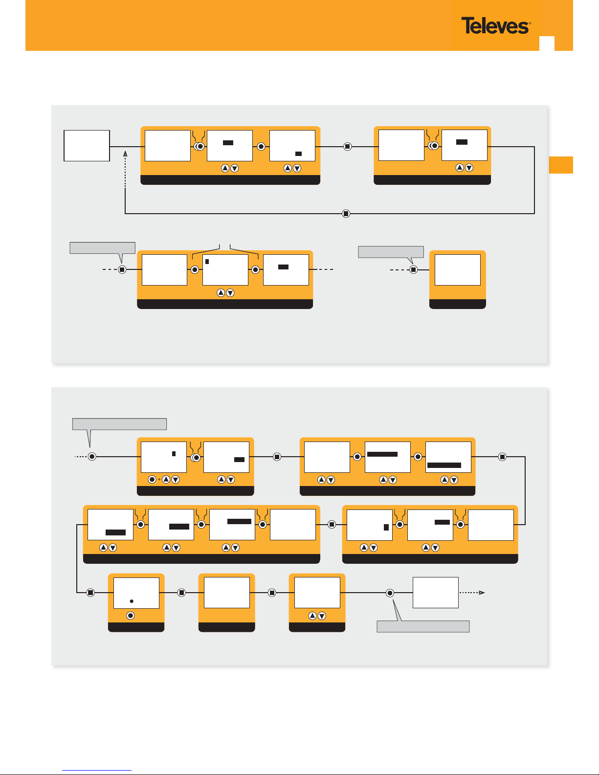
Estructura menús
Version de
firmware
unidad
V:x.xx
Conectar
programador
CONFIGURACIÓN DE SALIDA
GRABACIÓN
> 3 sec
Grabando los
Parametros y
Rearrancando
...
Desde cualquier menú
ASALIDA
Ch: C21
(471.25 MHz)
Nivel: 99
ASALIDA
Ch:
C21
(471.25 MHz)
Nivel: 99
ASALIDA
Ch: C21
(471.25 MHz)
Nivel:
99
ASALIDA
Ch: C21
(471.25 MHz)
Nivel: 99
ASALIDA
Ch: C21
(471.25 MHz)
Nivel: 99
CONMUTACION MODULO A / B
Desde cualquier menú
BSALIDA
Ch:
C21
(471.25 MHz)
Nivel: 99
(*)
(*)
CONFIGURACIÓN DE ENTRADA
(*)
AENTRADA
Ch: C22
(479.25 MHz)
AENTRADA
Ch:
C22
(479.25 MHz)
VERSIONESINFO TEMPERAT.
3 seg.
3 seg.
Desde cualquier menú principal
Desde cualquier menú extendido
ASALIDA
Ch: C21
(471.25 MHz)
Nivel: 99
Vers. FW.
Vx.xx
Vers. Boot
Vx.xx
TEMPERATURA
Act: 03
Max: 04
reset
IDIOMA MENUS
IDIOMA
Espa¤ol
Reset
CONFIG. CDC + ALIM. PREAMP.
(*)
CONFIGURACION CONV/AMP + TABLA CAN/FREC
CONFIGURACION BW + PENDIENTE EN CANALCONFIGURACION A/D + OFFSET EN DIGITAL
CONFIG ))
Preamp: off
Dir CDC:
123
CONFIG ))
Preamp:
off
Dir CDC: 123
ACONFIG ))
Tab canales:
Frecuencia
Conversor
ACONFIG ))
Tab canales:
Frecuencia
Conversor
ACONFIG ))
Tab canales:
Frecuencia
Conversor
ACONFIG ))
Pendiente: 0
BW ent: 8MHz
ACONFIG ))
Pendiente: 0
BW ent:
8MHz
ACONFIG ))
Pendiente:
0
BW ent: 8MHz
(*)(*)
ACONFIG ))
Entr: 125MHz
Sal:
125MHz
Modo:Digital
ACONFIG ))
Entr:
125MHz
Sal: 125MHz
Modo:Digital
ACONFIG ))
Entr: 125MHz
Sal: 125MHz
Modo:
Digital
ACONFIG ))
Entr: 125MHz
Sal: 125MHz
Modo:Digital
(*)(*)(*)
Menú
principal
Menú extendido
Page 6
PROCESADOR A/D TWIN
6
Important safety instructions
General installation conditions
• Before handling or connecting the equipment, please read this manual.
•
In order to reduce the risk of re or electric shock, do not expose the equipment
to rain or moisture.
• No quitar la tapa del equipo sin desconectarlo de la alimentación.
• No obstruir las ranuras de ventilación del equipo.
• Please allow air circulation around the equipment.
• The equipment must not come into contact with water or even be splashed
by liquids. Do not place containers with water on or near the equipment if it is
not adequately protected.
• Do not place the equipment near sources of heat or in excessively moisture
conditions.
• Do not place the equipment where it may be a ected by strong vibrations or
knocks.
• This symbol indicates that the equipment complies with the
safety requirements for equipment of marked CE.
Inputs/Outputs/Connections description
The unit (Fig. 1) is provided with:
1. RF Input (12V/24V/O )
2. RF Output (input loop-through)
3. RF input (output loop-through)
4. RF output
5. Power BUS connectors
6. Status LED
7. Control BUS connectors
8. Programmer / PC socket
Introduction
It allows to select any channel in the VHF or UHF band (46-862MHz) and
translate it in frequency to any position within these bands.
Technical specifi cations
NOTE: You have a complete User Guide on our website:
www.televes.com.
Links available at the end of this guide.
Down-Converter
Input frequency (selec.) MHz 46 - 862 IN/OUT Connectors tipo “F” hembra
Input level dBμV 50 a 80* Input impedance ohm. 75
Frequency steps
(selec.)
KHz
Analógico 250
Input line powering for preamps
(< 50 mA)
V 12 / 24 / OFF
Digital 166,66 / 125 Input loop-through gain dB 0 ± 3
F.I. Bandwidth (selec.) MHz 6 / 7 / 8
UP-Converter
Output frequency (selec.) MHz 46 - 862 Output loop-through losses (typ.) dB < 1,5
Frequency steps
(selec.)
KHz
Analógico 250 Return losses (typ.) dB > 12
Digital 166,66 / 125 IN/OUT Connectors tipo “F” hembra
Phase noise (typ.) dBc/Hz 80 @10KHz Output impedance ohm. 75
Output level dBμV 80 ±5 Spurious level (min.) dBc 60
Output level regulation dB > 15 Slope regulation dB ±3
General
Consumption (typ.) mA
400 @ 24V (LNB power OFF)
450 @ 24V
(LNB power ON)
Protection level IP20
* Automatic gain for high level input signals.
These technical speci cations are de ned for a maximum ambient temperature of 45 ° C (113 ° F). For higher temperatures forced ventilation is required.
Page 7
7
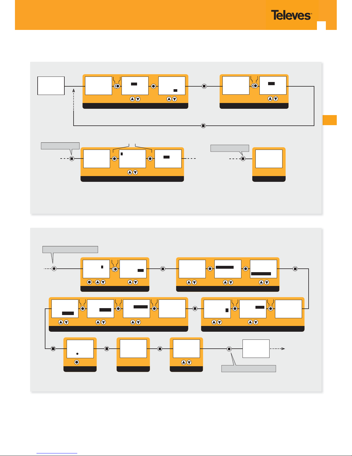
Menu structure
Unit
firmware
version
V:x.xx
Insert
programmer
unit
OUTPUT CONFIGURATION
SAVING
> 3 sec
Saving
settings and
restarting
...
From any menu
AOUTPUT
Ch: C21
(471.25 MHz)
Level: 99
AOUTPUT
Ch:
C21
(471.25 MHz)
Level: 99
AOUTPUT
Ch: C21
(471.25 MHz)
Level:
99
AOUPUT
Ch: C21
(471.25 MHz)
Level: 99
AOUPUT
Ch: C21
(471.25 MHz)
Level: 99
SWITCHING BETWEEN MODULES A / B
From any menu
BOUPUT
Ch:
C21
(471.25 MHz)
Level: 99
(*)
(*)
INPUT CONFIGURATION
(*)
AINPUT
Ch: C22
(479.25 MHz)
AINPUT
Ch:
C22
(479.25 MHz)
VERSIONSTEMPERAT. INFO
3 sec.
3 sec.
From any Main menu
From any Extended menu
AOUTPUT
Ch: C21
(471.25 MHz)
Level: 99
FW. Vers.
Vx.xx
Boot Vers.
Vx.xx
TEMPERATURE
Now: 03
Max: 04
reset
LANGUAGE MENU
LANGUAGE
English
Reset
CDC CONFIG. + PREAMP. POWER
(*)
CONV/AMP CONFIGURATION + CH/FREQ TABLES
BW CONFIGURATION + CHANNEL SLOPEA/D CONFIGURATION + OFFSET IN DIGITAL
CONFIG ))
Preamp: off
Addr CDC: 23
CONFIG ))
Preamp:
off
Addr CDC:123
ACONFIG ))
Chan. table:
Frequency
Converter
ACONFIG ))
Chan. table:
Frequency
Converter
ACONFIG ))
Chan. table:
Frequency
Converter
ACONFIG ))
Slope: 0
InputBW:8MHz
ACONFIG ))
Slope: 0
InputBW
8MHz
ACONFIG ))
Slope:
0
InputBW:8MHz
(*)(*)
ACONFIG ))
In: 125MHz
Out:
125MHz
Mode:Digital
ACONFIG ))
In:
125MHz
Out: 125MHz
Mode:Digital
ACONFIG ))
In: 125MHz
Out: 125MHz
Mode:
Digital
ACONFIG ))
In: 125MHz
Out: 125MHz
Mode:Digital
(*)(*)(*)
Main menu
Extended
menu
Page 8
8
Garantia
Televés S.A. ofrece una garantía de dos años calculados a partir de la fecha de
compra para los países de la UE. En los países no miembros de la UE se aplica la
garantía legal que está en vigor en el momento de la venta. Conserve la factura
de compra para determinar e sta fecha.
Durante el período de garantía, Televés S.A. se hace cargo de los fallos producidos por defecto del material o de fabricación. Televés S.A. cumple la garantía
reparando o sustituyendo el equipo defectuoso.
No están incluidos en la garantía los daños provocados por uso indebido, desgaste, manipulación por terceros, catástrofes o cualquier causa ajena al control
de Televés S.A.
Garantia
Televés S.A. o ers a two year guarantee, beginning from the date of purchase
for countries in the EU. For countries that are not part of the EU, the legal
guarantee that is in force at the time of purchase is applied. Keep the purchase
invoice to determine this date.
During the guarantee period, Televés S.A. complies with the guarantee by
repairing or substituting the faulty equipment.
The harm produced by improper usage, wear and tear, manipulation by a third
party, catastrophes or any other cause beyond the control of Televés S.A. is not
included in the guarantee.
Page 9

Page 10

Page 11
11
Instrucciones de uso
ES
www.televes.com/sites/default/fi les/HTE/564901_es.pdf
User instructions
EN
www.televes.com/sites/default/fi les/HTE/564901_en.pdf
Page 12

 Loading...