

Page 1
Ref. 563852
www.televes.com
TWIN HDMI/YPbPr/IP MPEG2/4 ENCODER/MODULATOR - QAM/COFDM/IP
EN
QUICK INSTALLATION GUIDE
GUÍA DE INSTALACIÓN RÁPIDA
TWIN HDMI/YPbPr/IP MPEG2/4 ENCODER/MODULADOR - QAM/COFDM/IP
ES
Page 2

Page 3
Important Safety Instructions
1. Read and Follow All Instructions - All the
safety and operating instructions should be
read prior to and followed while operating
this product.
2. Retain Instructions - The safety and
operating instructions should be retained
for future reference.
3. Heed Warnings - All warnings on the
product and in the operating instructions
should be adhered to.
4. Cleaning - Disconnect this product from
any electrical source before cleaning. Use
a damp cloth; do not use liquid or aerosol
cleaners.
5. Attachments - Do not use attachments
that are not recommended by the product
manufacturer as they may cause hazards.
6. Water and Moisture - Do not use this
product near any source of water.
7. Mounting – Do not place this product on
an unstable cart, stand, tripod, bracket,
or table. The product may fall, causing
serious injury to persons or nearby objects,
and serious damage to this product. Use
only with a cart, stand, tripod, bracket, or
table recommended by the manufacturer,
or sold with the product. Any mounting
of the product should follow the
manufacturer’s instructions, and should use
a mounting accessory recommended by the
manufacturer.
8. Ventilation – Slots and openings in
the chassis or cabinet are provided for
ventilation and to ensure reliable operation
of the product. These openings should
never be blocked or covered in any way. This
product should not be placed in any case,
cabinet, or rack unless proper ventilation
is provided and the manufacturer’s
instructions have been adhered to.
9. Power Sources - This product should be
operated only from the type of power
source indicated on the label.
10. Grounding or Polarization - Do not
bypass or defeat electrical plug polarization
or grounding. Doing so will violate the
warranty and may pose a risk of re or
electrocution.
11. Wire Protection – Ensure all connected
wiring is routed correctly to avoid damage
including pinching, excessive bends, or
compression.
12. Electrical Supply, Grounding, and Surge
Protection – Ensure that all local or national
electrical codes are followed. Seek the
advice of a licensed electrician, professional
engineer, or other licensed expert.
13. Power Lines - Always use caution and avoid
operating this or any connected equipment
near uninsulated power line or any other
hazards.
14. Object and Liquid Entry - Never allow
objects or liquid of any kind into this
product through openings. Doing so could
result in re or electric shock.
15. Servicing - There are no user serviceable
parts. Do not attempt to service this product
or remove covers. Doing so may expose you
to dangerous voltage or other hazards. Refer
all servicing to qualied service personnel.
Examples of damage requiring service
include but are not limited to:
y Damage to power-supply wiring.
y If liquid has been spilled, or objects have
fallen into the product.
y If the product has been exposed to rain
or water.
y If the product does not operate normally
by following the operating instructions.
Adjust only those controls that are
covered by the operating instructions as
an improper adjustment of other controls
may result in damage and will often
require extensive work by a qualied
technician to restore the product to its
normal operation.
y If the product has been dropped or
physically damaged.
y When the product exhibits a distinct
change in performance.
16. Replacement Parts - Ensure that repairs are
performed by qualied technicians and that
only manufacturer supplied or authorized
parts are used.
17. Safety Check - Upon completion of any
service or repairs to this product, ensure
safety checks to determine that the
product is functioning per manufacturer
specications are performed.
18. Heat - The product should be situated
away from heat sources such as radiators,
heat registers, stoves, or other products
(including ampliers) that produce heat.
Ensure that ambient temperature is
maintained in the manufacturer specied
operating range.
Safety instructions
Caution statements
Product inspection - Inspect the equipment
for shipping damage. Should any damage be
discovered, immediately le a claim with the
carrier.
Important Safety Instructions - To ensure
proper installation and operation, take a
moment to read this guide before proceeding
with the installation. If you have any questions
or comments about the T.0X Series - Encoders,
please contact your dealer.
WARNING:
TO PREVENT FIRE OR ELECTRICAL SHOCK
DO NOT EXPOSE TO RAIN OR MOISTURE.
CAUTION:
TO REDUCE THE RISK OF ELECTRIC SHOCK,
DO NOT REMOVE COVER.
NO USER-SERVICEABLE PARTS INSIDE.
REFER SERVICING TO QUALIFIED
PERSONNEL.
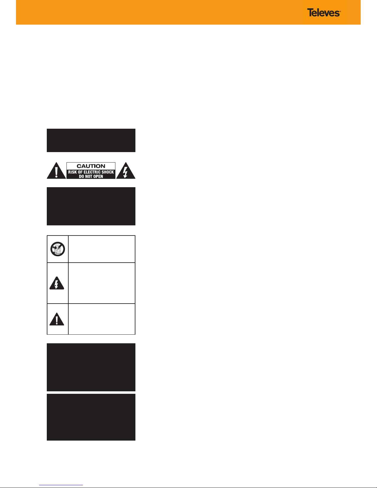
A product and cart combination should
be moved with care. Quick stops,
excessive force and uneven surfaces
may cause the product and cart
combination to overturn.
The lightning ash with arrow head
symbol, within an equilateral triangle,
is intended to alert the user to the
presence of uninsulated “dangerous
voltage” within the product’s enclosure
that may be of sucient magnitude
to constitute a risk of electric shock to
persons.
The exclamation point within an
equilateral triangle is intended to
alert the user to the presence of
important operating and maintenance
(servicing) instructions in the literature
accompanying the product.
WARNING:
TO REDUCE THE RISK OF FIRE OR
ELECTRIC SHOCK, DO NOT EXPOSE THIS
PRODUCT TO RAIN OR MOISTURE.
DO NOT OPEN THE CABINET,
REFER SERVICING TO QUALIFIED
PERSONAL ONLY.
CAUTION:
TO PREVENT ELECTRIC SHOCK, DO NOT
USE THIS (POLARIZED) PLUG WITH AN
EXTENSION CORD RECEPTACLE OR OTHER
OUTLET UNLESS THE BLADES CAN BE
FULLY INSERTED TO PREVENT BLADE
EXPOSURE.
Page 4
1. Lea y siga todas las instrucciones - Las instrucciones de seguridad y funcionamiento
deben leerse completamente antes de utilizar el producto.
2. Guarde las instrucciones - Las instruccio
nes de seguridad y operación deben conservarse como referencia.
3. Respete las advertencias - Deben respe
tarse todas las advertencias presentes en
el producto y en las instrucciones de operación.
4. Limpieza - Desconecte este producto de
cualquier fuente de alimentación antes de
limpiarlo. Utilice un paño ligeramente hu
medecido en agua y evite limpiadores líquidos o en aerosol.
5. Accesorios - No se deben utilizar accesorios
no recomendados por el fabricante del pro
ducto.
6. Agua y humedad - No use este producto
cerca de fuentes de agua.
7. Ventilación – Las ranuras y oricios del cha
sis sirven para ventilar y garantizar correcto
funcionamiento del producto. Estas aberturas no deben bloquearse ni cubrirse de ninguna manera. Este producto no debe instalarse en ningún contenedor, armario, etc., a
menos que exista una ventilación adecuada
y se respeten las instrucciones de uso.
8. Fuentes de alimentación - Este producto
deberá utilizarse solamente con el tipo de
corriente indicado en la etiqueta.
9. Toma de tierra / polarización - No se debe
cambiar la polaridad del enchufe o eliminar
la toma de tierra. Hacerlo viola la garantía y
puede suponer riesgo de incendio y/o elec
trocución.
10. Cableado – Asegúrese de que todo el ca
bleado conectado al equipo se instala correctamente para evitar daños tales como
dobleces, aplastamiento, y compresión.
11. Suministro eléctrico, conexión a tierra y
protección contra subidas de tensión –
Asegúrese de seguir todos los códigos eléc
tricos locales y nacionales. Busque el consejo de un electricista con licencia, ingeniero
profesional, u otro experto con licencia.
12. Líneas de alimentación - Sea precavido y
evite utilizar este equipo cerca de líneas de
alimentación no aisladas y peligros simila
res.
13. Entrada de objetos y líquidos - Nunca per
mita la entrada de objetos o líquidos de ningún tipo a través de las aberturas del equipo. Hacerlo podría provocar un incendio o
una descarga eléctrica.
14. Reparaciones - El equipo no contiene pie
zas que el usuario pueda reparar. No intente
reparar este producto o retirar la tapa. Si lo
hace, puede exponerse a voltajes peligrosos
y otros riesgos. Solicite siempre el servicio
de personal cualicado. Ejemplos de daños
que requieren servicios son:
y Daños en el cableado de alimentación.
y Si se ha derramado líquido o han caído
objetos dentro del producto.
y Si el producto ha sido expuesto a la lluvia
o al agua.
y Si el producto no funciona normalmente
siguiendo las instrucciones de funciona
-
miento. Ajuste sólo aquellos controles
que se indican en las instrucciones de
uso ya que un ajuste incorrecto de otros
controles puede resultar en daños y a menudo requerirá intervención de personal
cualicado para devolver el producto a su
funcionamiento normal.
y Si el producto se ha caído o dañado.
y Cuando el producto muestra un cambio
en su rendimiento.
15. Piezas de repuesto - Asegurarse de que
las reparaciones son realizadas por técnicos
cualicados y que sólo se utilizan repuestos
proporcionados o autorizados por el fabri
-
cante.
16. Seguridad - Al término de cualquier servicio
o reparación de este producto, asegúrese de
que se han pasado los controles de seguri
dad especicados por el fabricante para garantizar que el producto está funcionando
de acuerdo a las especicaciones de fábrica.
17. Calor - El producto debe instalarse lejos
de fuentes de calor tales como radiadores,
calefactores, estufas u otros productos (incluyendo amplicadores) que produzcan
calor. Asegúrese de que la temperatura
ambiente se mantiene en el rango de operación especicado por el fabricante en
todo momento.
Instrucciones generales y de
seguridad
Inspección del producto - Inspeccione el pro-
ducto y presente de inmediato una reclamación
a la compañía de transporte en caso de descubrir
cualquier daño.
Instrucciones importantes de seguridad - Para
garantizar la instalación y el funcionamiento ade
cuado del producto se debe leer esta guía antes
de proceder con su instalación. Si tiene alguna
pregunta o comentario sobre el producto, por
favor póngase en contacto con su distribuidor.
ADVERTENCIA:
PARA EVITAR RIESGO DE INCENDIO O
DESCARGA ELÉCTRICA NO EXPONGA ESTE
PRODUCTO A LA LLUVIA O HUMEDAD.
ADVERTENCIA:
PARA REDUCIR EL RIESGO DE DESCARGA
ELÉCTRICA, NO RETIRE LA TAPA. NO HAY
CONTROLES INTERNOS CONFIGURABLES
POR EL USUARIO. CONTACTAR CON
PERSONAL CUALIFICADO.
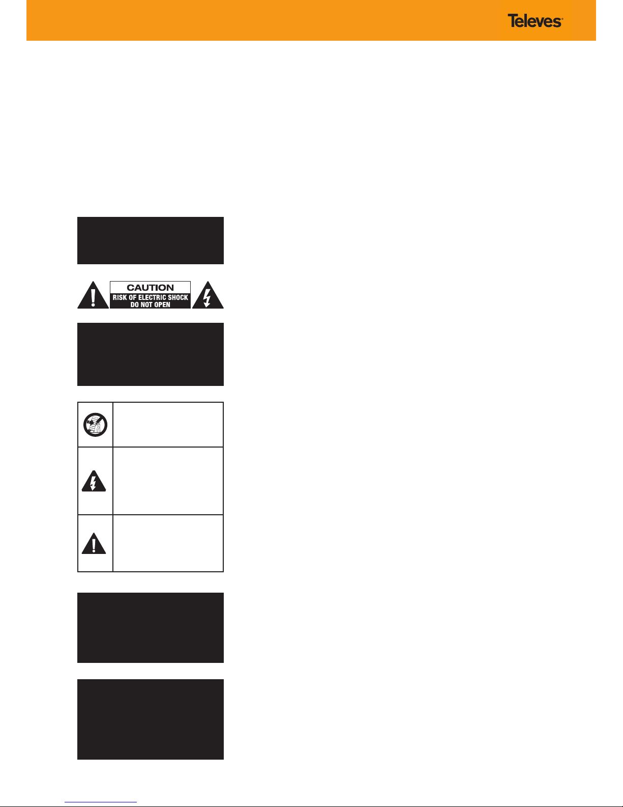
La combinación de producto y carro
debe moverse con cuidado. Las
paradas bruscas, la fuerza excesiva y las
supercies irregulares pueden hacer
que el producto y el carrito vuelquen.
Un símbolo de rayo con punta
de echa dentro de un triángulo
equilátero, pretende alertar al usuario
de la presencia de “voltaje peligroso”
dentro del producto que puede ser de
magnitud suciente para constituir un
riesgo de descarga eléctrica para las
personas.
Un signo de exclamación dentro
de un triángulo equilátero en la
documentación que acompaña al
producto, pretende alertar al usuario
de la presencia de instrucciones
importantes para su operación y
mantenimiento.
ADVERTENCIA:
PARA REDUCIR EL RIESGO DE INCENDIO O
DESCARGA ELÉCTRICA, NO EXPONGA ESTE
PRODUCTO A LA LLUVIA O HUMEDAD.
NO ABRA EL PRODUCTO, CONTACTAR
SIEMPRE CON PERSONAL CUALIFICADO.
ADVERTENCIA:
PARA EVITAR DESCARGAS ELÉCTRICAS, NO
USE NUNCA EL ENCHUFE POLARIZADO
PROPORCIONADO CON UNA EXTENSIÓN
U OTRO RECEPTÁCULO A MENOS QUE LOS
CONDUCTORES SE PUEDAN INSERTAR
COMPLETAMENTE Y NO QUEDEN
EXPUESTOS.
Page 5
TWIN HDMI/YPbPr/IP MPEG2/4 ENCODER/MODULATOR - QAM/COFDM/IP
UIPHDMI-QAC-T
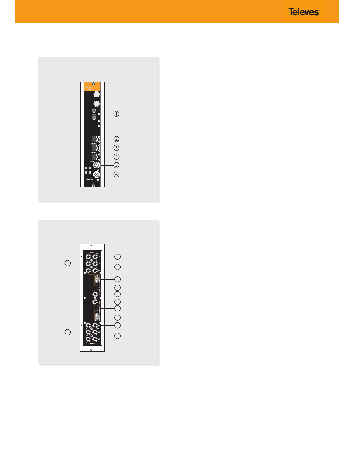
Rear view / Vista posterior
Front view / Vista frontal
Description of connectors / Descripción de los conectores
1.- Power connectors
Conectores alimentación
2.- Ethernet connector
Conector Ethernet
3.- Ethernet connector
Conector Ethernet
4.- Programmer connector
Conector Programador
5.- RF loop through input
Entrada lazo RF
6.- RF output
Salida RF
1.- YPbPr component input. Channel 1
Entrada por componentes YPbPr. Canal 1
2.- CVBS input. Channel 1
Entrada CVBS. Canal 1
3.- Analog (L/R) audio input. Channel 1
Entrada audio analógica (L/R). Canal 1
4.- HDMI input. Channel 1
Entrada HDMI. Canal 1
5.- SPDIF digital optical audio input. Channel 1
Entrada audio digital óptica SPDIF. Canal 1
6.- SPDIF digital coaxial audio input. Channel 1
Entrada audio digital coaxial SPDIF. Canal 1
7.- SPDIF digital coaxial audio input. Channel 2
Entrada audio digital coaxial SPDIF. Canal 2
8.- SPDIF digital optical audio input. Channel 2
Entrada audio digital óptica SPDIF. Canal 2
9.- HDMI input. Channel 2
Entrada HDMI. Canal 2
10.- YPbPr component input. Channel 2
Entrada por componentes YPbPr. Canal 2
11.- CVBS input. Channel 2
Entrada CVBS. Canal 2
12.- Analog (L/R) audio input. Channel 2
Entrada audio analógica (L/R). Canal 2
Page 6
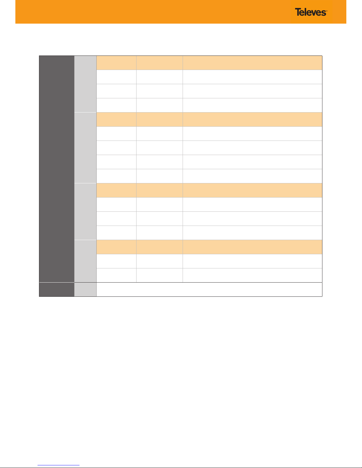
LED indicators / LEDs de estado
Front LED alarms
Alarmas (LEDs)
panel frontal
TEMP
Color
Internal temp
Temperatura interna
Comment
Situación
Solid green
Verde, jo
Normal
Safe
Seguro
Slow blink orange
Naranja, parpadeo lento
High
Alta
Warning *
Atención
Fast blink red
Rojo, parpadeo rápido
Very High
Muy Alta
Danger
Peligro
CH1 – CH2
Color
Channel status
Estado del canal
Comment
Situación
O
Apagado
Disabled
Deshabilitado
Channel disabled.
Canales deshabilitados.
Solid green
Verde, jo
Lock
Enganchado
Input locked and unit encoding audio/video.
Entradas enganchadas y unidad codicando audio/video.
Solid red
Rojo, jo
Unlock
Desenganchado
Input unlocked and unit not encoding audio/video.
Entradas desenganchadas y unidad no codicando audio/video.
Blinking red
Rojo, parpadeando
Boot
Unit starting up.
Unidad reiniciando.
OUTPUT
Color
Output mode
Modo salida
Comment
Situación
Solid green
Verde, jo
Normal
Output RF channel is ON, broadcasting audio/video (normal mode).
Canal RF de salida encendido, transmitiendo audio/video (modo normal).
Slow blinking green
Verde, parpadeo lento
Carrier wave, null, or muted
Portadora, nulo o apagado
Output RF channel is OFF or in an alternate signal mode.
Canal RF de salida está apagado o en un modo de señal alterno.
Solid orange/red
Naranja/rojo, jo
Normal
Cong bitrate doesn´t t in output
El bit rate congurado no cabe en la señal de salida
LOOP
Color
Output loop status
Estado del lazo de salida
Comment
Situación
Solid green
Verde, jo
ON
Encendido
Output loop-through enabled. Units may be daisy-chained using the internal combiner.
Lazo de salida habilitado. Las unidades se pueden combinar usando el mezclador interno.
O
Apagado
OFF
Apagado
Output loop-through disabled. Units must be combined using an external combiner.
Lazo de salida deshabilitado. Debe usarse un mezclador externo para combinar unidades.
Back LED indicators
LEDs posteriores
A/V inputs
Entradas A/V
Indicate the currently selected audio and video inputs and where the input signals should be connected.
Indican las entradas de audio y video seleccionadas actualmente y dónde se debe conectar la señal de entrada.
Page 7
Installation
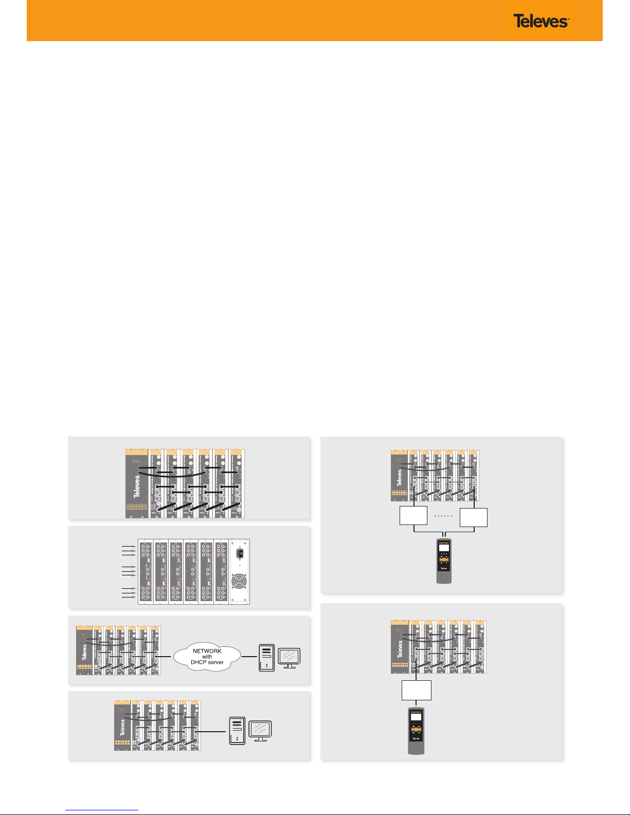
1. Install all units in the rack and connect them as shown in Fig. 1.
2. The audio and video input signals connect to the back of the modules
(Fig. 2).
3. If a network is available that provides IP addresses through DHCP, connect
the encoders to the network as shown in Fig. 3. If such a network is not
available, then a computer will need to be connected as shown in Fig. 4.
4. Power on the units.
5. Connect the programmer to each unit and set a unique number in the
“# ID” eld according to the order of installation of the units in the rack
(Fig. 5).
6. Connect the programmer to a unit, usually the rst one, and read the IP
address (Fig. 6).
Each unit can work as a master controller for the other units. All units can
be congured by connecting to only one.
7. If a network was connected in Step 3 then proceed to step 8. If not, set the
address of you computer as follows:
IP value = 172.20.0.2
netmask = 255.0.0.0
gateway = 172.20.0.3
NOTE: The default factory conguration of the units has an IP address in this
range (it should be dierent for each unit). If a unit was ever provided
an address before, manually or through DHCP, this unique address may
no longer exist. Resetting to IP factory defaults, will return the original
unique private address though.
8. In your web browser, enter the IP address from Step 6 as the URL.
A login prompt will appear. By default the parameters are:
Login: encoder
Password: encoder
Instalación
1. Instale todas las unidades en el rack y conéctelas como se indica en la
Fig. 1.
2. Conecte en la parte posterior de los módulos las señales de entrada de
audio y video (Fig. 2).
3. Si dispone de una red que proporcione una dirección IP mediante un
servidor DHCP, conecte los encoders a la red como se indica en la Fig. 3.
Si la red no está disponible, deberá usar un PC para la conexión como se
indica en la Fig. 4.
4. Encienda las unidades.
5. Conecte el programador a cada unidad y asigne un único número en el
campo “# ID” de forma que coincidan con el orden de las unidades en el
rack (Fig. 5).
6. Conecte el programador a una unidad, normalmente la primera, y lea la
dirección IP (Fig. 6).
Cada unidad puede funcionar como maestra controlando las otras. Se
pueden controlar todas las unidades conectándose solo a una.
7. Si se conectó a una red en el paso 3, siga en el paso 8. Si no, establezca la
dirección de su PC de la siguiente forma:
IP = 172.20.0.2
Netmask = 255.0.0.0
Gateway = 172.20.0.3
NO TA: La conguración de fábrica por defecto de las unidades tiene una
dirección IP en este rango (ésta debe ser diferente para cada unidad). Esta
dirección única no existirá si la unidad fue programada anteriormente,
manualmente o mediante DHCP. Reseteando la IP a valores de fábrica,
recuperará la dirección original única.
8. Teclee en su navegador Web la IP del paso 6 como dirección URL.
Aparecerá un mensaje de login. Los parámetros por defecto son:
Nombre de usuario: encoder
Contraseña: encoder
TWIN HDMI/YPbPr MPEG2/4 ENCODER/MODULATOR - ISDBTb/DVB-T
TWIN HDMI/YPbPr MPEG2/4 ENCODER/MODULATOR - ISDBTb/DVB-T
TWIN HDMI/YPbPr MPEG2/4 ENCODER/MODULATOR - ISDBTb/DVB-T
TWIN HDMI/YPbPr MPEG2/4 ENCODER/MODULATOR - ISDBTb/DVB-T
TWIN HDMI/YPbPr MPEG2/4 ENCODER/MODULATOR - ISDBTb/DVB-T
TWIN HDMI/YPbPr MPEG2/4 ENCODER/MODULATOR - ISDBTb/DVB-T
Fig. 1
Fig. 2
Fig. 3
Fig. 4
Fig. 5
Fig. 6
Page 8
La página Status > Summary ( Fig. 7) será la primera en aparecer.
Ésta proporciona un resumen de todas las unidades instaladas en la red y
ordenadas por el número indicado en el paso 5.
La Fig. 8 muestra un ejemplo de una página de “status” detallada.
9. Congure todas las unidades:
Seleccione “CONFIGURATION”. Esta página tiene 5 pestañas: INPUT,
TRANSPORT, OUTPUT, IP y NETWORK mostradas de la Fig. 9 a la 14.
La última columna de cada página de conguración es “Select”. Cualquier
cambio hecho será guardado sólo en las unidades con la opción “Select”
marcada cuando pulse “Apply Selected“. Esto se aplica a las cinco
pestañas que hay bajo el menú “Conguration”.
Algunos elementos tienen una opción de conguración automática.
Por ejemplo, la página de conguración de red permite cambiar de esta
forma el número asignado en el paso 5 del proceso de instalación.
La opción “Auto” pedirá conrmación al haber modicado los parámetros
de todas las unidades jados en el paso 5 y el orden probablemente no
se corresponderá con la posición de las unidades en el rack.
9.1 INPUT
Conguración de las entradas físicas de audio y video. En el caso de
que la resolución sea 1080p será necesario seleccionar la codicación
H.264.
9.2 TRANSPORT
Modicación de los parámetros del Transport Stream de salida. El TS ID,
SID y LCN de cada servicio no podrán coincidir con los de otro servicio
de la misma unidad.
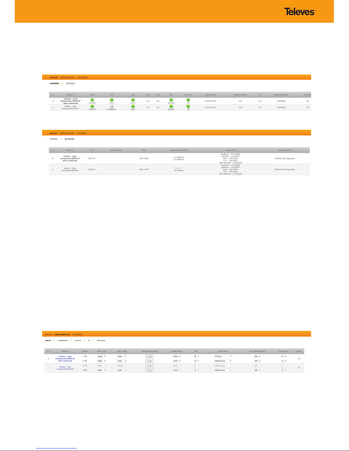
The Status > Summary page ( Fig. 7) should appear as the rst page.
This provides a summary of all the units installed in the network and the units
will be sorted by the number entered in Step 5.
Fig. 8 shows an example of a detailed “status” page.
9. Congure all units:
Select “CONFIGURATION”. This page has 5 tabs: INPUT,
TRANSPORT, OUTPUT, IP and NETWORK shown in Fig. 9 to 14.
The last column of each conguration page is “Select”. Any changes made
will be saved only in the units with the “Select” option checked when you
click “Apply Selected”. This applies to the ve tabs that exist under the
“Conguration” menu.
Some items have a choice of automatic conguration. For example, the
Network Conguration page allows you to change the number assigned
in step 5 of the installation process.
The “Auto” option will request conrmation to have changed the
parameters of all units set in step 5 and order probably will not
correspond with the position of the units in the rack.
9.1 INPUT
Conguration of the physical inputs audio and video. It will be
necessary to select the encoding H.264 if the resolution is 1080p.
9.2 TRANSPORT
Changing the parameters of the output Transport Stream. The TS ID,
SID and LCN of each service shall not overlap with those of another
service the same unit.
Fig. 7 - Status > Summary
Fig. 8 - Status > Detailed
Fig. 9 - Input
Page 9
9.3 OUTPUT
Conguración del canal RF de salida. En el caso de cambiar de modo
entre QAM y COFDM la unidad se reiniciará.
9.4 IP
La unidad puede trabajar en 3 modos distintos de IP: Input, Output
y Disabled.
Input: Para la recepción de servicios IP, es necesario que la unidad esté
en modo Input y tenga conguradas las direcciones IP y los puertos.
Las direcciones IP permitidas son las comprendidas entre 224.0.0.0 y
239.255.255.255.
Si no es así, realice los cambios oportunos en la pestaña IP (Fig. 12) y
pulse “ Apply Selected”.
Si intenta congurar dos direcciones IP y puertos iguales, la Web
le avisará de que no es una conguración válida y no le permitirá
aplicar la conguración.
Una vez esté todo congurado, pulse el botón “Select” asociado a
Fig. 13 - IP (2)
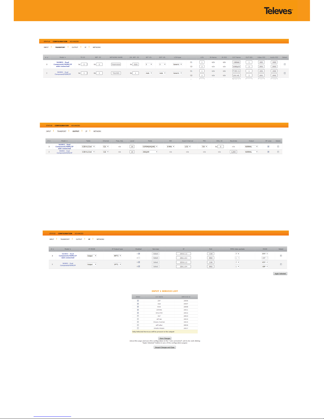
9.3 OUTPUT
Setting the RF output channel. The unit will restart, if you switch between
QAM and COFDM mode.
9.4 IP
The unit can work in 3 dierent modes IP, Input, Output and Disabled.
Input: To receive IP services, It’s necessary that the unit is in Input mode
and you set the IP addresses and ports. Allowed IP addresses between
224.0.0.0 y 239.255.255.255.
If not, make changes on the IP tab (Fig. 12) and click “ Apply Selected”.
If you try to congure two IP addresses and ports equal the Web
will warn you that is not a valid conguration and will not let you
apply settings.
Once everything is set up, press the “Select” button associated with
Fig. 12 - IP
Fig. 10 - Transport
Fig. 11 - Output
Page 10
cada dirección IP y se abrirá una ventana como la de la Fig. 13. Si
no aparece ningún servicio espere hasta que acabe de realizarse
el escaneo.
En ella se pueden ver los servicios disponibles para la IP
correspondiente.
Seleccione los servicios que desea visualizar y presione sobre
“Store Changes”.
Finalmente, para aplicar la conguración pulse “Apply Selected”. Los
servicios seleccionados aparecerán en la pestaña “ TRANSPORT”
junto a los servicios de las entradas físicas.
Output: Para la transmisión de los servicios de las entradas físicas
mediante IP, debe tener la unidad en modo “Output”, seleccionar
si desea que el tipo de salida sea MPTS o SPTS y congurar las
direcciones IP y los puertos.
En modo SPTS, la entrada física 1 saldrá por la IP 1 y la entrada
física 2 por la IP 2.
En caso de estar en modo MPTS, las dos entradas físicas saldrán
por una única IP.
Si
alguna de las entradas físicas está deshabilitada, su
correspondiente servicio IP no tendrá transporte.
9.5 NETWORK
Conguración de las opciones de red. Tanto la dirección IP como
la máscara de red sólo se podrán modicar si el modo DHCP está
deshabilitado (Fig. 14).
10 Ventana de conguración completa:
Para modicar cualquier valor del encoder desde una sola ventana,
seleccione “CONFIGURATION”. Pulse en el nombre de la unidad y se
mostrará la página de la Fig. 15. Desde esta página puede modicar
cualquier parámetro de la conguración de la unidad seleccionada.
each IP address and a window appears like Fig. 13. If no appear
any service, wait until the end of the scan.
Here you can see the services available to the corresponding IP.
Select the services you want to display and click on “Store Changes”.
Finally, to apply the conguration, click “Apply Selected”. The
selected services will appear in the “Transport” tab next to the
services of the physical inputs.
Output: For services transmissions of physical inputs via IP, the unit
must be in “Output” mode; if you want, you can choose between
MPTS or SPTS output types and congure IP addresses and ports.
In SPTS mode, the physical input 1 will exit through the IP 1 and
physical input 2 by the IP 2.
In MPTS mode, the two physical inputs will exit by a single IP.
If any of the physical inputs is disabled, its corresponding IP service
will not have transport.
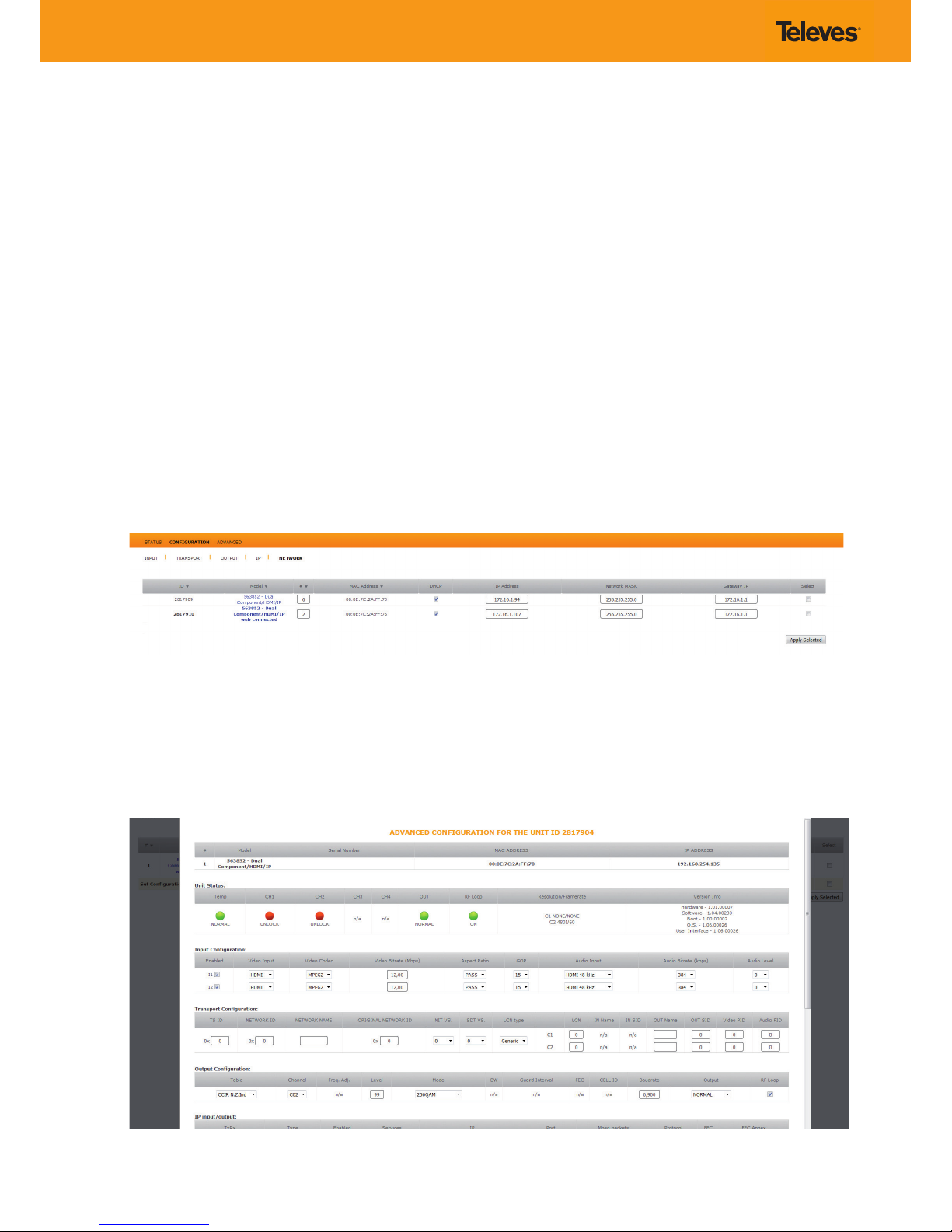
9.5
NETWORK
Conguring network options. Both the IP address and the network
mask may only be changed if DHCP mode is disabled (Fig. 14).
10 Complete conguration window:
To change any encoder value from a single window, select
“CONFIGURATION”. Click on the name of the unit and the page Fig. 15,
is displayed. From this page, you can modify any parameter settings for
the selected unit.
Fig. 15 - Advanced Conguration
Fig. 14 - Network
Page 11
- OUTPUT FREQ STEP
166 KhZ
- TEMP NOW: 46 C
MAX: 86 C
- OUTPUT BANDWIDTH
8 Mhz
QAM MODE ONLY
Frequency mode only/
Solo modo frecuencia
Frequency mode only/
Solo modo frecuencia
563852
- OUTPUT -
SELECT OUT
SPECTRUM
NORMAL
- UNIT IP
MODE
DHCP ON
* Next page/
Página siguiente
12.00 Mbps
IP1 SERV
1/2
SERVICE 1
ON
NAME 1/1
1.SERVICE
1
OUT:SERVICE
LCN 1/1
1.SERVICE
1
N:0005
INPUT 1/2
Selected
INPUT IP
Selected
(RX Mode Only)
SID 1/1
1.SERVICE
1
00001
00003
IP MENU*
Enable edit mode /
Position cursor
(in edit mode) /
Disable edit mode.
Activar el modo
edición / Posición
del cursor (en modo
edición) / Desactivar
el modo edición.
Change section /
Save parameters
(press and hold
for 3 sec.)
Cambiar sección /
Guardar datos (pulse
y mantenga pulsado
3 seg.)
Change menu /
Modify value
(in edit mode)
Cambiar menú /
Modicar valores
(en modo edición)
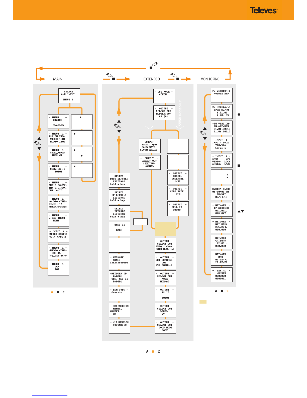
Menu ow chart / Estructura del menú
For programming Unit operation / Para operaciones de programación de la unidad.
Page 12
PORT NUMBER
OUTPUT 1
01100
PORT NUMBER
OUTPUT MUX
01100
- OUTPUT IP OUTPUT 1
ENABLE
- INPUT IP INPUT 1
ENABLE
- OUTPUT IP OUTPUT MUX
ENABLE
- OUTPUT IP FORMAT
SPTS
- IP MODE -
RX MODE
- UNIT ID -
0001
- N PACKETS OUTPUT 1
7
- N PACKETS OUTPUT MUX
7
-IP ADRESS OUTPUT 1
225.000.
001.001
-IP ADRESS INPUT 1
225.000.
001.001
-IP ADRESS OUTPUT MUX
225.000.
001.001
- RTP -
OUTPUT 1
ENABLE
- RTP -
OUTPUT MUX
ENABLE
- RTP -
OUTPUT 2
ENABLE
- OUTPUT IP OUTPUT 2
ENABLE
- N PACKETS OUTPUT 2
7
-IP ADRESS OUTPUT 2
225.000.
001.001
PORT NUMBER
OUTPUT 2
01100
SELECT
DEFAULT
SETTINGS
Hold key
PORT NUMBER
INPUT 1
01100
PORT NUMBER
INPUT 2
01100
- RTP INPUT 1
ENABLE
- RTP INPUT 2
ENABLE
- INPUT IP INPUT 2
ENABLE
-IP ADRESS INPUT 2
225.000.
001.001
RX MODE DISABLED
TX MODE
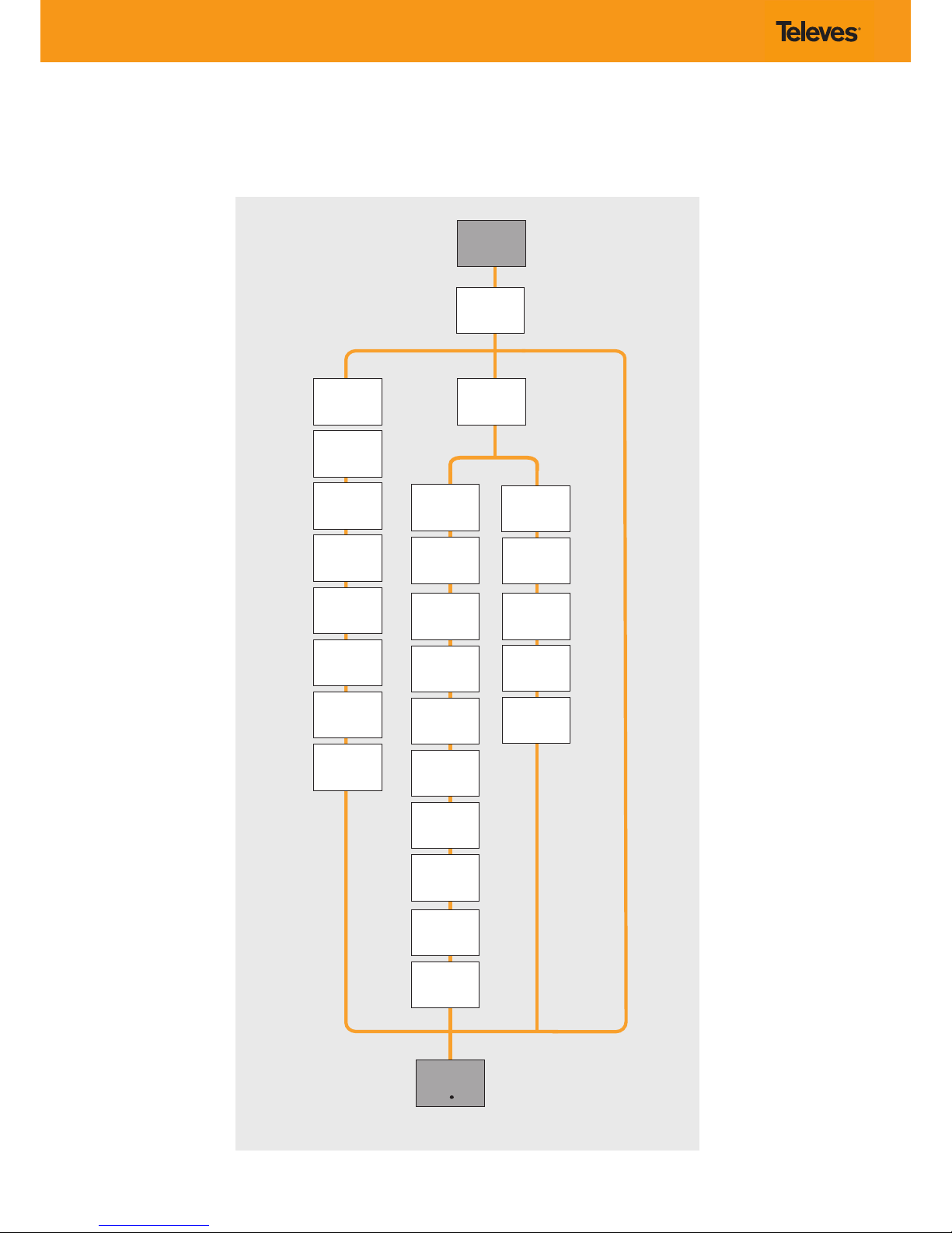
IP menu/ Menú IP
For programming Unit operation / Para operaciones de programación de la unidad.
Page 13
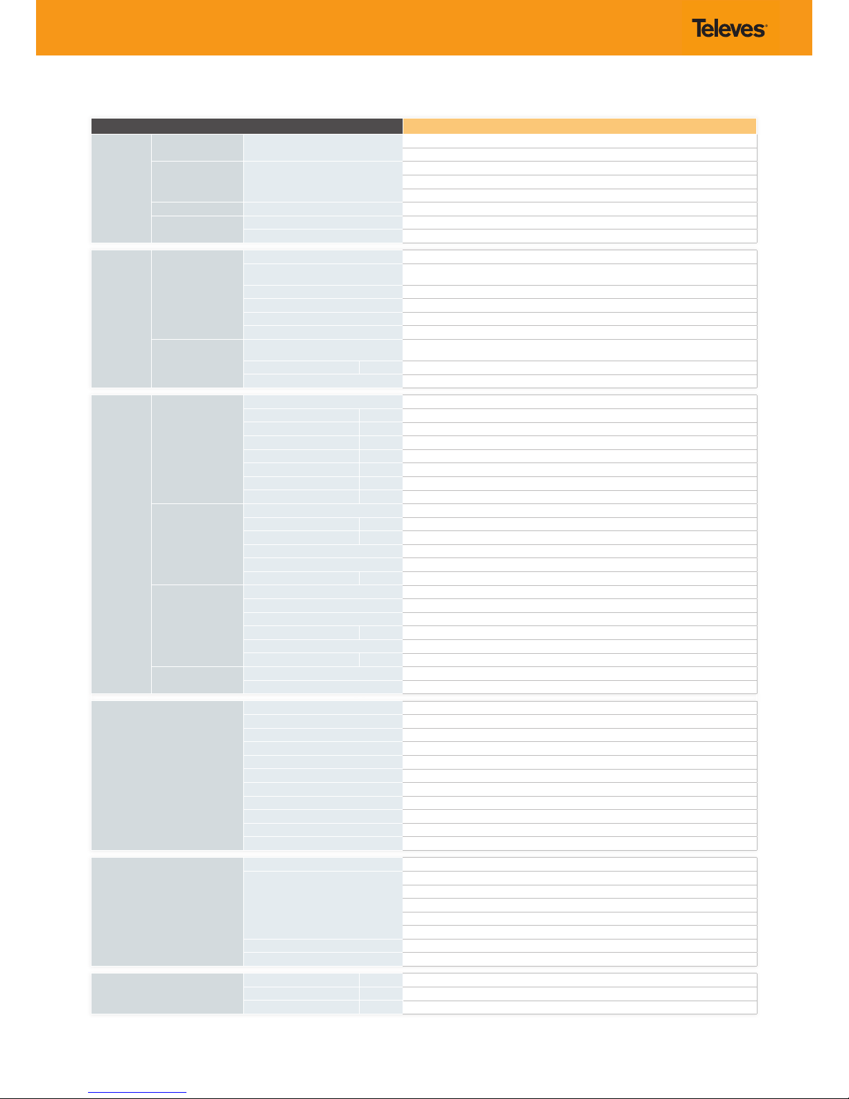
Technical specications
Reference 563852
INPUTS
VIDEO Connectors
2 sets - 3x RCA for Video (Y, Pb, Pr)
2 sets - 1x RCA for CVBS Video
AUDIO Connectors
2 sets - 2x RCA for Analog Audio (L, R)
2 sets - 1x RCA for Digital Audio
2 sets - 1x Toslink for Digital Audio (Optical)
VIDEO + AUDIO Connectors 2 sets - 1x HDMI
IP MULTICAST
Connectors 2x RJ45 (Switch Gigabit)
Formats SPTS or MPTS (UDP/RTP)
ENCODING
PROFILE
VIDEO
Output Format MPEG-2 / H.264
Resolution
480i, 480p, 576i, 576p, 720p, 1080i & 1080p
(1)
Supports auto-scan for input resolution
Aspect Ratio 4:3, 16:9, and pass through
GOP 10, 12, 15, 16, 18, 20, 24 or 30
Transport rate Variable
Video bit rate Variable
AUDIO
Output format
Dolby Digital AC-3 (only digital passthrough) or
MPEG1 Layer2 (analog input or HDMI uncompressed PCM audio)
Sampling rate kHz 48
Output bitrate Variable
OUTPUT
RF
Connectors 1x “F” Female
Frequency Range MHz 46 ... 862
Max output level dBµV +115 (+103 with loop-through)
MER dB >40 (typ)
Spurious dBc -60
Impedance Ω 75
I/Q Phase Error º <1
I/Q Amplitude Imbalance % <1
QAM
Modulation format 16, 32, 64, 128, 256
BaudRate Mbaud 6,9
Roll-o % 15
Code Reed Solomon
Spectrum Mode Normal / Inverted
Frequency Step KHz 250
COFDM
Modulation format QPSK, 16QAM, 64QAM
Guard Interval 1/4, 1/8, 1/16, 1/32
FEC 1/2, 2/3, 3/4, 5/6, 7/8
Bandwidth MHz 6, 7, 8
Cell_id Editable
Frequency Step KHz 125 / 166
IP MULTICAST
Connectors 2x RJ45 (Switch Gigabit)
Formats SPTS or MPTS (UDP/RTP)
PSI PARAMETERS
Transport Stream ID Editable
Original Network ID Editable
Network ID Editable
Logical Channel Number Editable
NIT Version Manual / Automatic
SDT Version Manual / Automatic
Type LCN Generic / UK / NorDig V1 / NorDig V2
Network Name Editable
Service PID Editable
Service Name Editable
Service ID Editable
MONITORING / CONTROL
Local control Full conguration with LCD handheld programmer
Local monitoring
LOOP status LED
OUTPUT status LED
TEMP status LED
CH1/CH2 status LEDs
Ethernet status LEDs
Remote monitoring Centralized web based remote control, management, alarms, and software upgrades
Control Daisy-chain integrated ethernet switch
GENERAL
Power supply Vdc 24
Power disipation W <20.4
Operating Temperature ºF / ºC 32 to 95 / 0 to 35
(1) 1080p resolution is only supported with MPEG-4 video codec.
The technical specications are dened for an ambient temperature of 35 ºC (95 ºF). It shall always be installed with forced ventilation.
Page 14
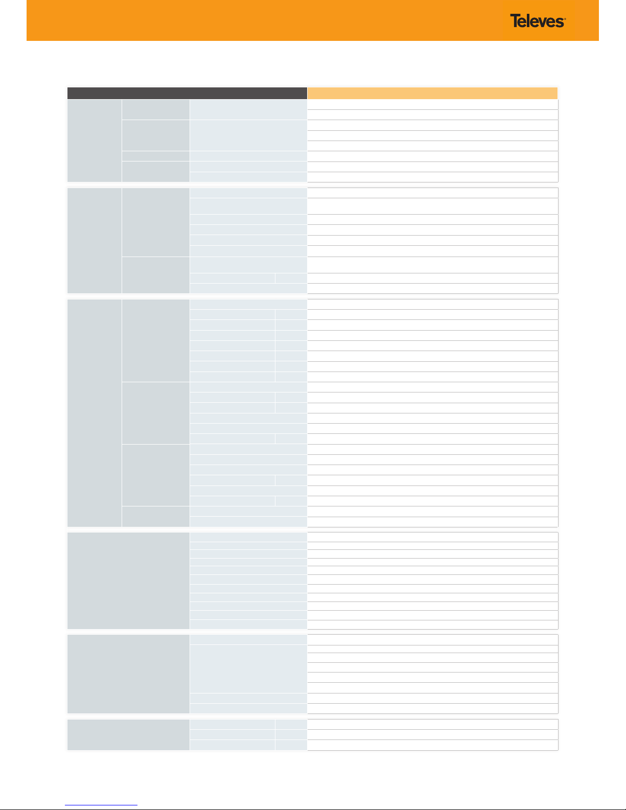
Características técnicas
Referencia 563852
ENTRADA
VIDEO Conectores
2 juegos - 3x RCA para Video (Y, Pb, Pr)
2 juegos - 1x RCA para Video CVBS
AUDIO Conectores
2 juegos - 2x RCA para Audio analógico (L, R)
2 juegos - 1x RCA para Audio Digital
2 juegos - 1x Toslink para Audio Digital (Óptico)
VIDEO + AUDIO Conectores 2 sets - 1x HDMI
IP MULTICAST
Conectores 2x RJ45 (Switch Gigabit)
Formatos SPTS o MPTS (UDP/RTP)
PERFIL DE
CODIFICACION
VIDEO
Formato de salida MPEG-2 / H.264
Resolución
480i, 480p, 576i, 576p, 720p, 1080i & 1080p
(1)
Soporta auto-scan para resolución de entrada
Relación de aspecto 4:3, 16:9, y paso
GOP 10, 12, 15, 16, 18, 20, 24 or 30
Tasa de transporte Variable
Velocidad de bits de vídeo Variable
AUDIO
Formato de salida
Dolby Digital AC-3 (solo paso digital) o
MPEG1 Layer2 (entrada analógica o HDMI de audio PCM sin comprimir)
Frecuencia de muestreo kHz 48
Tasa de bits de salida Variable
SALIDA
RF
Conectores 1x “F” Female
Margen de frecuencia MHz 46 ... 862
Nivel máx. de salida dBµV +115 (+103 con bucle)
MER dB >40 (typ)
Espúreos dBc -60
Impedancia Ω 75
I/Q Phase Error º <1
I/Q Amplitude Imbalance % <1
QAM
Formato de modulación 16, 32, 64, 128, 256
BaudRate Mbaud 6,9
Roll-o % 15
Código Reed Solomon
Modo espectro Normal / Invertedo
Pasos de frecuencia KHz 250
COFDM
Formato de modulación QPSK, 16QAM, 64QAM
Intervalo de guarda 1/4, 1/8, 1/16, 1/32
FEC 1/2, 2/3, 3/4, 5/6, 7/8
Ancho de banda MHz 6, 7, 8
Cell_id Editable
Pasos de frecuencia KHz 125 / 166
IP MULTICAST
Connectores 2x RJ45 (Switch Gigabit)
Formatos SPTS o MPTS (UDP/RTP)
PARAMETROS PSI
Transport Stream ID Editable
Original Network ID Editable
Network ID Editable
Número lógico de canal (LCN) Editable
Version NIT Manual / Automatico
Version SDT Manual / Automatico
Tipo LCN Generico / UK / NorDig V1 / NorDig V2
Nombre de red Editable
PID del servicio Editable
Nombre del servicio Editable
ID del servicio Editable
MONITORIZACION / CONTROL
Control local Conguración completa con programador LCD
Monitorización local
LED estado LOOP
LED estado OUTPUT
LED estado TEMP
LEDs estado CH1/CH2
LED estado Ethernet
Monitorización remota Web centralizada para control remoto, gestión, alarmas y actualizaciones software
Control Switch ethernet integrado para conexión en cascada
GENERAL
Alimentación Vdc 24
Consumo W <20.4
Temperatura funcionam. ºF / ºC 32 to 95 / 0 to 35
(1) resoluciones de 1080p sólo son compatibles con codecs de vídeo MPEG-4.
Las características técnicas descritas se denen para una temperatura ambiente de 35 ºC (95ºF). Se deberá instalar siempre con ventilación forzada.
Page 15
DECLARACIÓN DE CONFORMIDAD DECLARATION OF CONFORMITY DECLARAÇÃO DE CONFORMIDADE DECLARATION DE CONFORMITE
DICHIARAZIONE DI CONFORMITÀ DEKLARACJA ZGODNOŚCI KONFORMITÄTSERKLÄRUNG ΠΙΣΤΟΠΟΙΗΤΙΚΟ ΣΥΜΜΟΡΦΩΣΗΣ FÖRSÄKRAN OM
ÖVERENSSTÄMMELSE ДЕКЛАРАЦИЯ СООТВЕТСТВИЯ
https://doc.televes.com
Page 16

televes.com
 Loading...