

Page 1
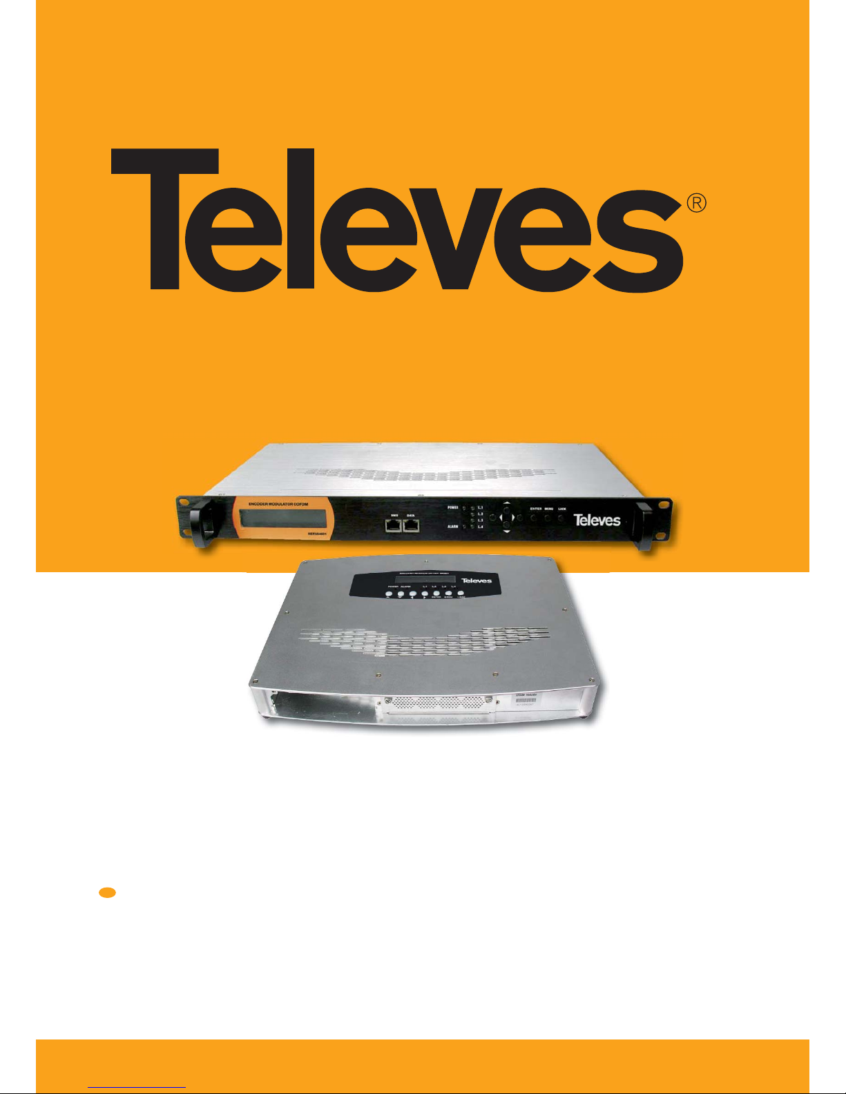
DVB-T Modulators
EN
Refs. 554501
554601
User´s Manual
www.televes.com
Page 2

Page 3

ENGLISH
EN
Index
CHAPTER 1 INTRODUCTION . . . . . . . . . . . . . . . . . . . . . . . . . . . . . . . . . . . . . . . . . . . . . . . . . . . . . . . . . 4
1.1 PRODUCT OVERVIEW . . . . . . . . . . . . . . . . . . . . . . . . . . . . . . . . . . . . . . . . . . . . . . . . . . . . . . . . . 4
1.2 PRINCIPLE CHART . . . . . . . . . . . . . . . . . . . . . . . . . . . . . . . . . . . . . . . . . . . . . . . . . . . . . . . . . . . . 4
1.3 SPECIFICATION . . . . . . . . . . . . . . . . . . . . . . . . . . . . . . . . . . . . . . . . . . . . . . . . . . . . . . . . . . . . . . 4
CHAPTER 2 PRODUCT DESCRIPTION . . . . . . . . . . . . . . . . . . . . . . . . . . . . . . . . . . . . . . . . . . . . . . . . . . 5
2.1 INDICATORS AND KEY-BUTTONS DETAILS . . . . . . . . . . . . . . . . . . . . . . . . . . . . . . . . . . . . . . . . 5
2.2 INSTALLATION PRECAUTIONS . . . . . . . . . . . . . . . . . . . . . . . . . . . . . . . . . . . . . . . . . . . . . . . . . . 6
CHAPTER 3 OPERATION . . . . . . . . . . . . . . . . . . . . . . . . . . . . . . . . . . . . . . . . . . . . . . . . . . . . . . . . . . . . . 6
3.1 BUTTON INTRODUCTION . . . . . . . . . . . . . . . . . . . . . . . . . . . . . . . . . . . . . . . . . . . . . . . . . . . . . . 6
3.2 INITIAL STATUS . . . . . . . . . . . . . . . . . . . . . . . . . . . . . . . . . . . . . . . . . . . . . . . . . . . . . . . . . . . . . . 6
3.3 GENERAL SETTING FOR MAIN MENU . . . . . . . . . . . . . . . . . . . . . . . . . . . . . . . . . . . . . . . . . . . . 6
CHAPTER 4 ENCODERS . . . . . . . . . . . . . . . . . . . . . . . . . . . . . . . . . . . . . . . . . . . . . . . . . . . . . . . . . . . . . 7
4.1 SPECIFICATION . . . . . . . . . . . . . . . . . . . . . . . . . . . . . . . . . . . . . . . . . . . . . . . . . . . . . . . . . . . . . . 8
CHAPTER 5 WEB NMS OPERATION . . . . . . . . . . . . . . . . . . . . . . . . . . . . . . . . . . . . . . . . . . . . . . . . . . . . 8
5.1 LOGIN . . . . . . . . . . . . . . . . . . . . . . . . . . . . . . . . . . . . . . . . . . . . . . . . . . . . . . . . . . . . . . . . . . . . . 8
5.2 CONFIGURATION SETTING . . . . . . . . . . . . . . . . . . . . . . . . . . . . . . . . . . . . . . . . . . . . . . . . . . . . 8
CHAPTER 6 TROUBLESHOOTING . . . . . . . . . . . . . . . . . . . . . . . . . . . . . . . . . . . . . . . . . . . . . . . . . . . . . 11
CHAPTER 7 APPLICATION . . . . . . . . . . . . . . . . . . . . . . . . . . . . . . . . . . . . . . . . . . . . . . . . . . . . . . . . . . . 11
7.1 ORDERING GUIDELINE . . . . . . . . . . . . . . . . . . . . . . . . . . . . . . . . . . . . . . . . . . . . . . . . . . . . . . . . 11
7.2 APPLICATION EXAMPLE . . . . . . . . . . . . . . . . . . . . . . . . . . . . . . . . . . . . . . . . . . . . . . . . . . . . . . . 12
7.3 CONFIGURATION EXAMPLE FOR MORE THAN ONE UNIT IN THE SAME INSTALLATION . . . 14
Page 4
DVB-T Modulator
4
Chapter 1. Introduction
1.1 Product overview
Ref. 554501 and Ref. 554601 are respectively a wall mount and a rack, DVB-T
modulation integrated device to convert HD A/V signals to DVB-T RF out in
the frequency range of 30~960 MHz. It has equipped with 2 encoder slot, and
1 RF input. The signals source could be from satellite receivers, closed-circuit
television cameras, Blue-ray players, and antenna etc. its output signal is to be
received by a DVB-T standard TV, DVB-T STB. The device can be used in public
place such as metro, market hall, theatre, hotels, resorts, etc for advertising. It
also can be used for monitoring, training and educating in company, schools,
campuses, hospital…be sides that it’s a good choice for bars to o er HD sports
channels, for VIP entertainment channels, and more.
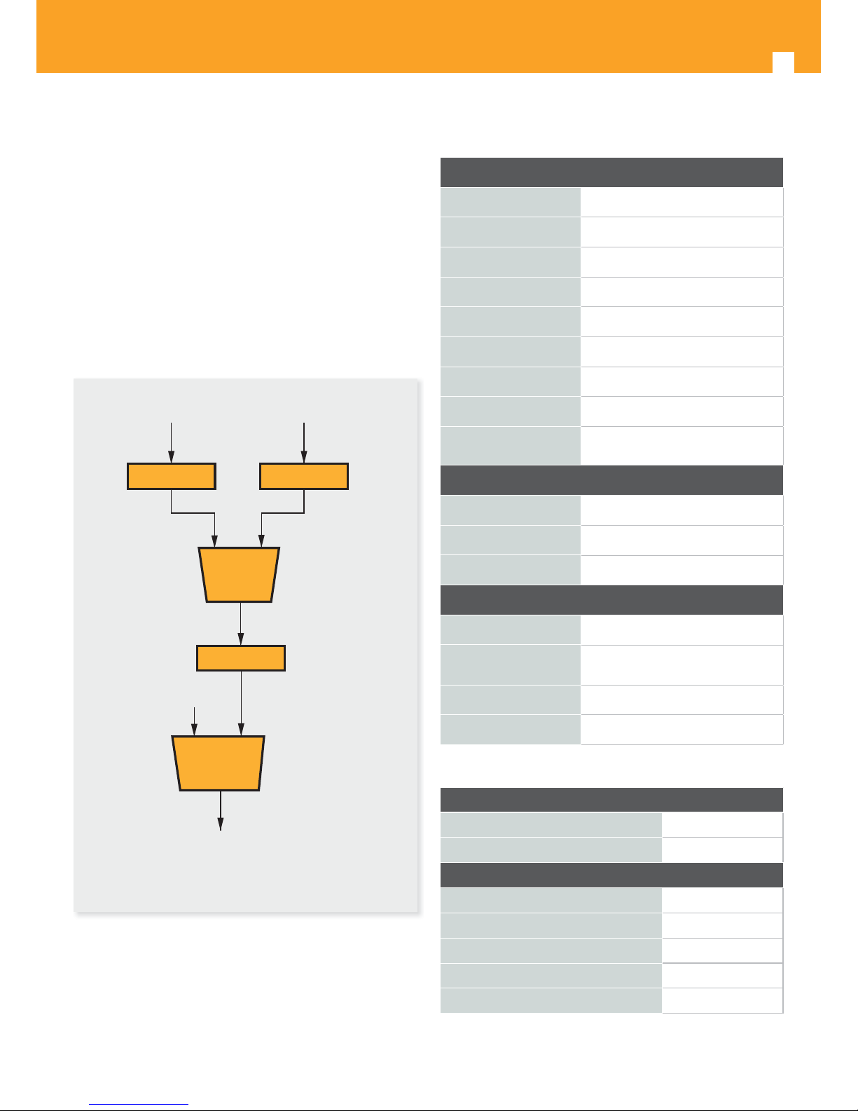
1.2 Principle chart
IN IN
Encoder Encoder
MUX
Modulator
Combiner
RF IN
RF OUT
1.3 Speci cation
DVB-T modulator section
Standard
EN300744
FFT mode 2K, 8K
Bandwidth 6M, 7M, 8M
Constellation QPSK, 16QAM, 64QAM
GuardInterval 1/4, 1/8, 1/16, 1/32
FEC 1/2, 2/3, 3/4, 5/6, 7/8
MER ≥42dB
RF frequency 30~960MHz, 1KHz step
RF output level
-30~ -10dBm (81~97 dBμV),
0.1dB step
Interface
Local interface
LCD + control buttons
Remote management Web NMS
Language
English, French
General
Power supply
AC 100V~240V
Dimensions
360 x 280 x 50 mm (554501)
480 x 300 x 44 mm ( 554601)
Weight 2.6 kgs
Operation temperature 0~45 ºC
Con gurations
LCN con g
Ye s
NIT Table con g
Ye s
Settings
Network Name
Ye s
Network ID Yes
Transport Stream ID (TSID) Yes
Original Network ID (ONID) Yes
Hierarchy Information Yes
Page 5
EN
5
Chapter 2. Product Description
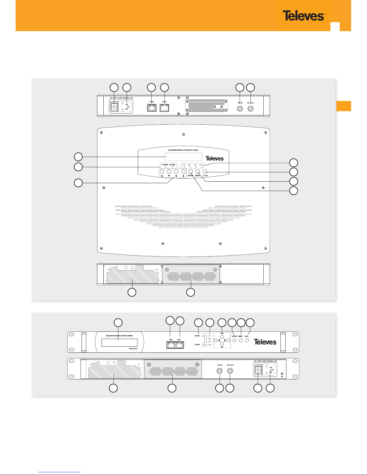
2.1 Indicators and Key-buttons details
(1) LCD window: LCD display
(2) NMS port: input NMS
(3) DATA port: IP output
(4) Power and alarm light
(5) Lock light
(6) Up and down, left and right button
(7) Enter button: for con rm
(8) Menu button: for back step
(9) Lock button: press to lock set
(10) Encoder Slot 1 (open)
(11) Encoder Slot 2 (with tap)
(12) RF in
(13) RF out
(14) Power Switch
(15) Power Supply Slot
10
10
12
11
12 13 14 15
2
3
2 3
1
5
9
8
7
4
6
12 131514
4 5 6 7 8 91
554501
554601
Page 6
DVB-T Modulator
6
2.2 Installation precautions
This section to explain the cautions the users must have to avoid any injures
when using or installing the product. For this reason, please read all details here
before installing or using the product.
General Precautions
Must be operated and maintained free of dust or dirty.
The cover should be securely fastened, do not open the cover of the products
with the power on.
After use, securely stow away all loose cables, external antenna, and others.
Power precautions
When you connect the power source, make sure it will not cause any overload.
Avoid operating on a wet oor in the open. Make sure the extension cable is
in good condition.
Make sure the power switch is o before you start to install the device.
Grounding Requirement
All function modules’ good grounding is the basis of reliability and stability of
devices. Also, they are the most important guarantee of lightning arresting and
interference rejection. Therefore, the system must follow this rule.
Grounding conductor must be a copper conductor in order to reduce high
frequency impedance, and the grounding wire must be as thick and short as
possible.
Users should make sure the both ends of grounding wire are electric
conducter and antirust.
It is prohibited to use any other device as part of grounding electric circuit.
The area of the conduction between grounding wire and device’s frame
should be no less than 25mm
2
Chapter 3. Operation
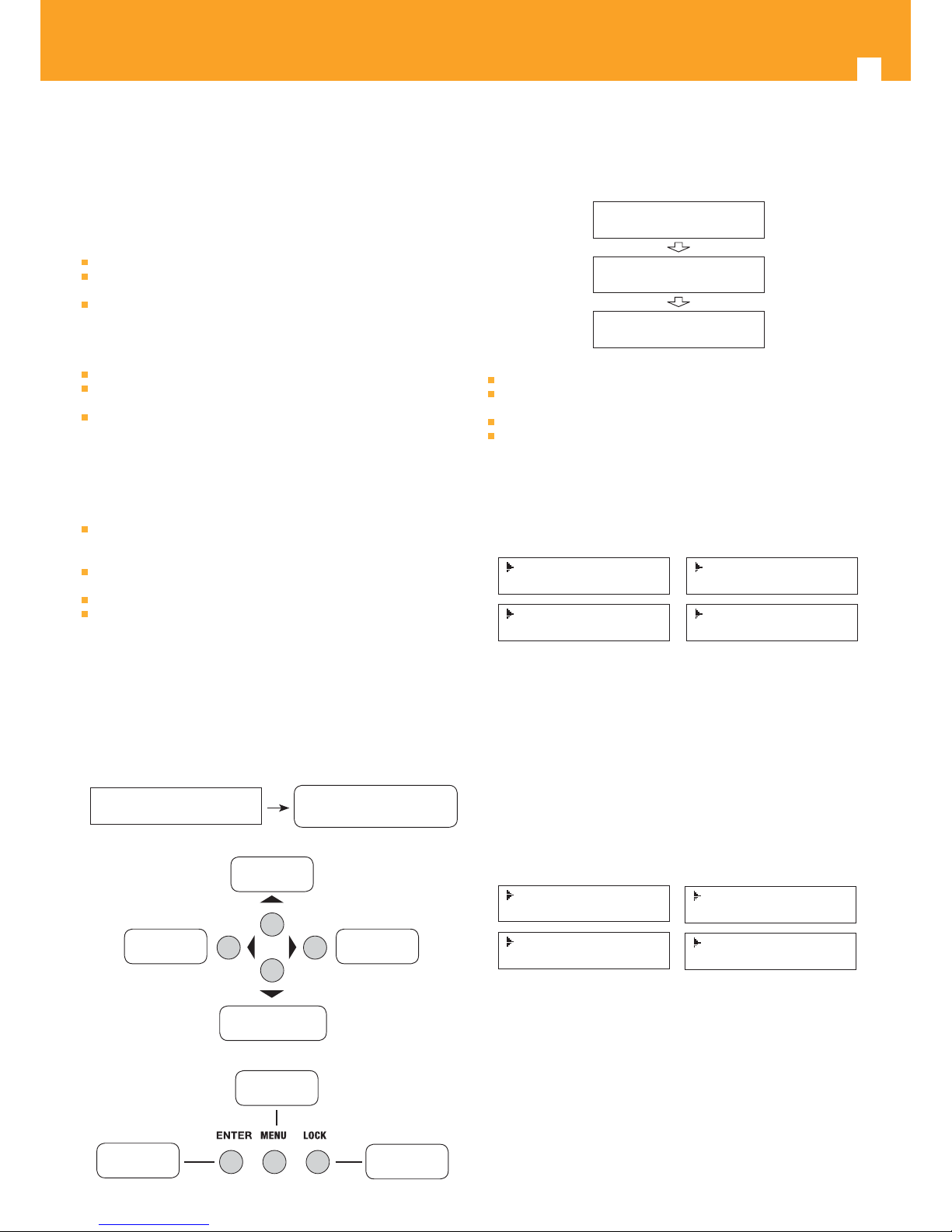
3.1 Button introduction
LCD display window
Display window for seting menu
Status display when power on
DVB-T XXX.00MHz
X.XXMbps 0.0M
Setting value up
and moving up
To move left To move right
Setting value down
and moving down
Back step
Con rm setting
Lock button
3.2 Initial Status
Switch On, then below status will be displayed, few seconds’ initialization then
open startup picture
Start up ...
Start OK ...
DVB-T XXX.00MHz
X.XXMbps Y.YYMbps
DVB-T: indicate the modulation standard of this device
XXX.XX MHz: indicate the input frequency, and the frequency range is
30~960MHz
X.XX Mbps: indicate the encoding bit rate in slot 1
Y.YY Mbps: indicate the encoding bit rate in slot 2
3.3 General setting for Main Menu
By pressing “Lock” key to enter the main menu, the LCD will display the
following pages:
1 Alarm Status
2 Encode Setting
3 Modulate Setting
4 IP Output Setting
5 Network Setting
6 Saving Config
7 Loading Config
8 Version
User pressing UP or DOWN buttons to speci ed menu item, and then pressing
ENTER to enter the submenus as below:
1) Alarm status --- the alarm indicator will light on if there is no A/V signals
input.
2) Encoder setting --- choose this submenu, the LCD will show “input setting”,
press the ENTER key and control the UP or Down key to move the arrow.
User could nd how to set the audio and video encoding bit rate.
3) Modulator setting
When the “modulator setting” submenu has been chosen, users can nd below
di erent parameters for setting. And the LCD window would respectively show
like these.
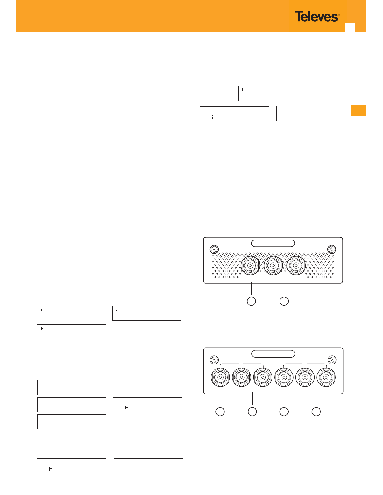
3.1 Bandwidth
3.2 Constellation
3.3 Transmisson Mod
3.4 Guard Interval
3.5 Code Rate
3.6 RF Frequency
3.7 RF Outlevel
- Bandwidth
There are three possible options provided for selecting bandwidth: 6M, 7M, and
8M. When the display shows them, user just need swift LEFT and RIGHT key to
choose and repressing “ENTER” for con rm.
- Constellation
Three di erent constellations: QPSK, 16QAM, and 64QAM will be show on the
LCD window when Constellation been entered.
- QPSK: Quadrature Phase Shift Keying, Selecting this option indicates the
device works as DVB-S modulation mode
- 16QAM: Quadrature Amplitude Modulation is 16
- 64QAM: Quadrature Amplitude Modulation is 64
Setting method just the same, when the display shows them, user just need
Page 7
EN
7
swift LEFT and RIGHT key to choose and repressing “ENTER” for con rm.
- Trans mode
After entering Trans mode, the LCD would show the current working mode.
User can move LEFT/RIGHT key and repress ENTER key to select and con rm.
2K and 8K are the options.
- 2K: when the device works as current mode, the number of current carrier
is 2048.
- 8K: when the device works as current mode, the number of current carrier
is 8192.
- Guard interval
In communications, guard intervals are used to ensure that distinct
transmissions do not interfere with one another. These transmissions may
belong to di erent users (as in TDMA) or same user (as in OFDM).
The purpose of the guard interval is to introduce immunity to propagation
delays, echoes and re ections, to which digital data is normally very sensitive.
There are four possible options provided to be selected. They are 1/4, 1/8, 1/16,
1/32. User can shift the LEFT/RIGHT key to select and press ENTER to con rm.
- FEC
Forward Error Correction (FEC) rates include 1/2, 2/3, 3/4, 5/6, and 7/8. After
entering FEC submenu, and the LCD display would shows them, users just need
press LEFT and RIGHT button to choose, and press ENTER button for con rm.
- RF Frequency
The RF output frequency range is from 30 to 1000MHz with 1K stepping. After
entering the RF frequency setting submenu, users the can press LEFT, RIGHT,
UP, and DOWN buttons to adjust the frequency and con rm by press ENTER
button.
- RF out level
The RF attenuation range is from -30~-10dbm (81~97dbμV) with 0.1dB step.
After entering this setting submenu, user can shift UP/DOWN/LEFT/RIGHT key
to set the output level and press ENTER to con rm.
4) IP Output Setting
???????
5) Network setting
After inter netwok setting, there are three Submenu Items for setting, just show
as the following LCD display pictures.
5.1 IP Address
5.2 Subnet Mask
5.3 Gateway
5.4 MAC Address
5.5 Reset Password
5.6 Web Manage Port
User can press “UP/DOWN” to choose this item. “Enter” and “LEFT/RIGHT” to
set the parameters.
Note: The MAC address is according to the factory setting, and it’s unique. The
display will respectively show as below:
IP Address
192.168.000.136
Subnet mask
255.255.255.000
Gateway
192.168.000.001
MAC Address
201110140940
Reset pasword ?
Yes No
6) Save con g
Users enter save con g submenu for saving settings. Choose yes for con rm set.
Save Configuration?
Yes No
Saving config ...
7) Loading con g
At this menu, user can press UP/DWON key to select and repress ENTER to
con rm. User can restore the device into the last saved con guration by
choosing “6.1” and restore the device into factory con guration by choosing
“6.2” the display will show as below:
7.1 Load Saved CFG
7.2 Load Default
Load Saved CFG ?
Yes No
Loading config ...
8) Version
User can check the hardware version and software version of this equipment
when enter this submenu.
EncoderModulator
SW 5.13 HW 5.0
Chapter 4. Encoders
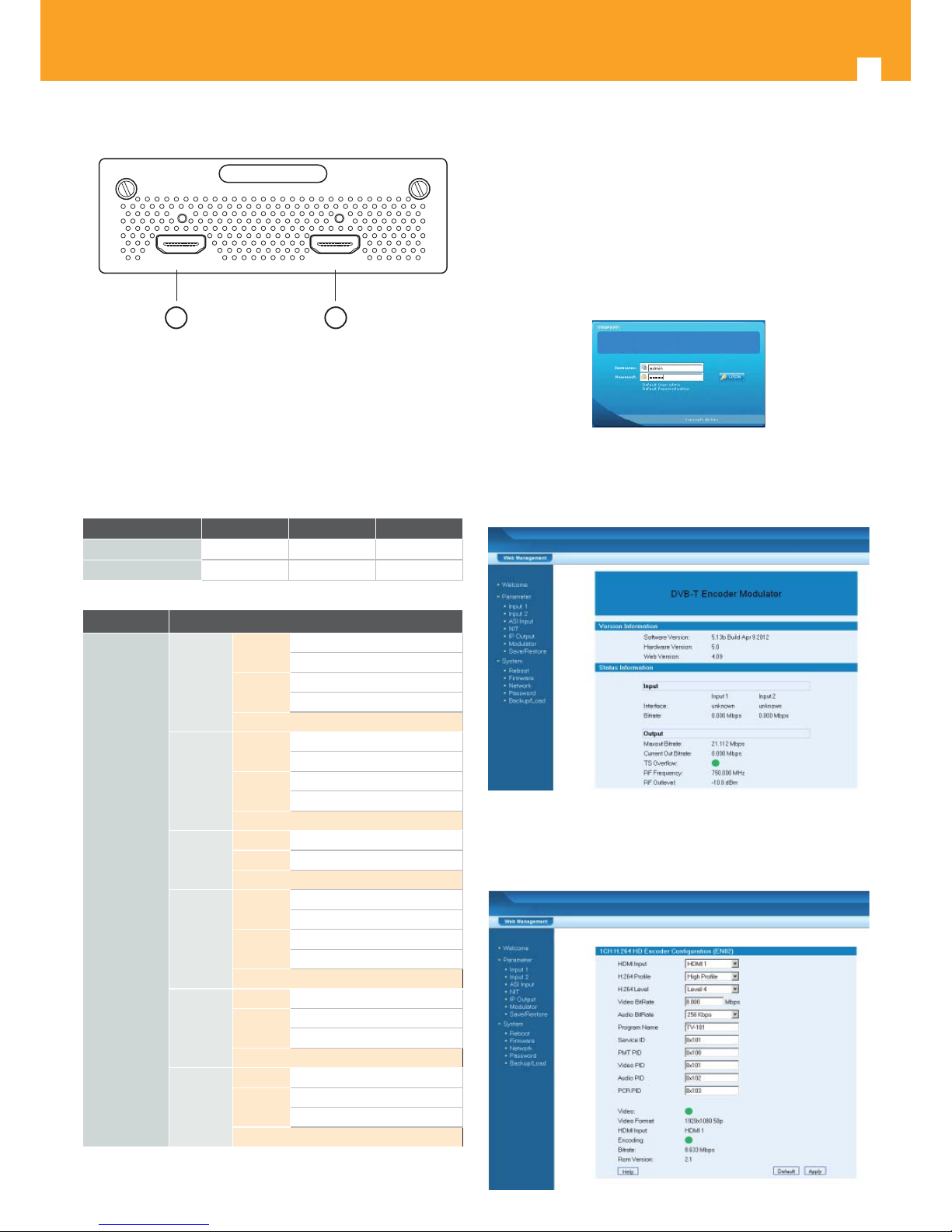
Ref. 554801 – 1 A/V Input
CVBS L ---- Audio ---- R
1
2
(1) CVBS input (video input)
(2) Unbalanced audio input (left and right)
Ref. 554802 – 2 A/V Inputs
CVBS L ---- Audio ---- R CVBS L ---- Audio ---- R
12
1 3
2 4
(1) CVBS input (video input) –Channel 1
(2) Unbalanced audio input (left and right) –Channel 1
(3) CVBS input (video input) –Channel 2
(4) Unbalanced audio input (left and right) –Channel 2
Page 8
DVB-T Modulator
8
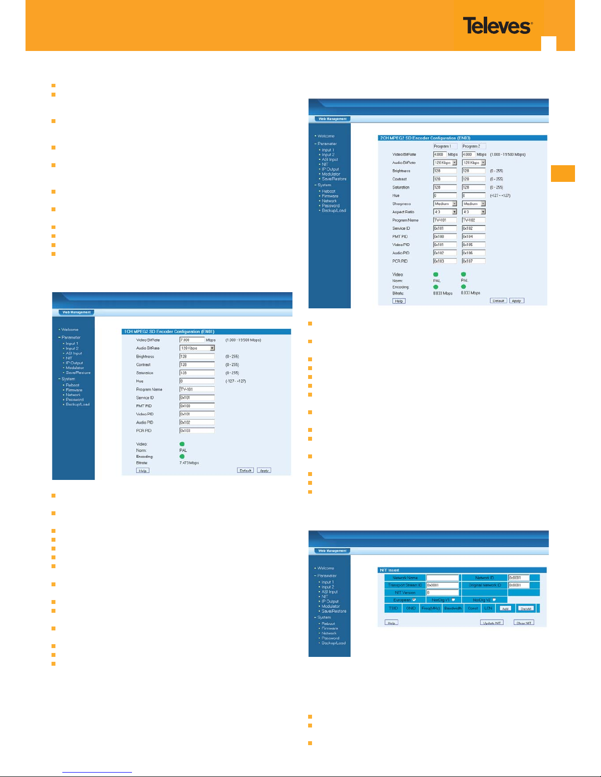
Ref. 554803 – 1 HDMI Input
HDMI1 HDMI2
1
2
(1) HDMI input –Channel 1
(2) HDMI input –Channel 2
Note: Is only possible to obtain on the output the signal of one input at a time.
When both input have signal at the same time, the signal on the output is the
one of HDMI1(if HDMI input is set in automatic see chapter 5.2, otherwise the
output will be from the input selected).
4.1 Speci cation
Ref. 554801 554802 554803
Video Compression
MPEG-2 SD MPEG-2 SD H264 HD
Audio Compression MPEG-2 SD MPEG-2 SD MPEG-2 SD
Encoding mode MPEG-2 / H264 / AVC SD / HD
Input port
Option 1
Port 1
One channel CVBS input
Unbalanced audio input
Port 2
One channel CVBS input
Unbalanced audio input
RF input
Option 2
Port 1
Two channel CVBS input
Unbalanced audio input
Port 2
Two channel CVBS input
Unbalanced audio input
RF input
Option 3
Port 1 One channel of HDMI input
Port 2 One channel of HDMI input
RF input
Option 4
Port 1
Two channel CVBS input
Unbalanced audio input
Port 2
One channel CVBS input
Unbalanced audio input
RF input
Option 5
Port 1 One channel of HDMI input
Port 2
Two channel CVBS input
Unbalanced audio input
RF input
Option 6
Port 1 One channel of HDMI input
Port 2
One channel CVBS input
Unbalanced audio input
RF input
Chapter 5. WEB NMS operation
User not only can use front buttons for setting con guration, but also can
control and set the con guration in computer by connect to web NMS Port. User
should ensure that the computer’s IP address is di erent from the NDS3542’s IP
address; otherwise, it would cause IP con ict.
5.1 Login
A login interface will pop up rstly when user entered the IP address:
http://192.168.1.137, the interface shows as follow picture. Both of the default
user name and password are admin.
User will face welcome interface after login, and all setting options are been
listed on the left side. And the main window at the right shows version
information and status information. (All the example pictures been showed
here just window captures pictures when the device connected in our test
room, status shows on the picture just for reference, they are not xed value)
5.2 Con guration setting
1) HDMI input setting
Page 9
EN
9
HDMI Input: Display which HDMI port is used (Only for HDMI Band Input).
H.264 Pro le: user can set the H.264 Pro le in this area, there are four possible
options provided to be selected: Automatic, High Pro le, Main Pro le and
Baseline Pro le.
H.264 Level: user can set the H.264 Level in this area, there are twelve possible
options provided to be selected: Automatic, Level 1.2, Level 1.3, Level 2, Level
2.1, Level 2.2, Level 3, Level 3.1, Level 3.2, Level 4, Level 4.1 & Level 4.2.
Video bit rate: user can set the video bit rate in this area, the range is
1~19.5Mbps.
Audio bit rate: user can set the audio bit rate in this area, there are ve possible
options provided to be selected: 64kbps, 96kbps, 128kbps, 192kbps, 256kbps
and 320kbps. The default value is 128kbps.
Program name: it shows current program information. User can select and
type the program name to be played as needed.
PMT/Video/Audio/PCR PID: in this area, user can set program PIDs as needed,
usually system will automatically select the default values.
Encoding and video light: the light should show green color normally
HDMI input: it shows if there is real-time HDMI signal inputting
Video format: the current video format of the device
Bit rate: the current encoding bit rate
2) 1 A/V input setting
Video BitRate: The range of values from 1.000 to 19.500 Mbps. For SD signal,
3.000 Mbps is ok, HD signal at least need 6.000 Mbps.
Audio BitRate: Audio encode bitrate con guration. You can select the suitable
audio bitrate from list.
Brightness: The range of values from 0 to 255 (Only for SD signal).
Contrast: The range of values from 0 to 255 (Only for SD signal).
Saturation: The range of values from 0 to 255 (Only for SD signal).
Hue: The range of values from -127 to 127 (Only for SD signal).
Program Name: Only support character and number. The length can not over
32 byte
Service ID: Also called progam number, it is must di erent from other
program. If you change it,you should modify the LCN.
PMT PID: Program Mapping Table PID
Video: Green is normal, red means signal input error, please check signal input
and video format.
Encoding: Green is normal, red means encoder is not work, please check
signal input and video format.
Norm: Display the video format of the input (Only for SD signal).
Video Format: Display the video format of the input (Only for HD signal).
Bitrate: Display the current encoder bitrate.
3) 2 A/V input setting
Video BitRate: The range of values from 1.000 to 19.500 Mbps. For SD signal,
3.000 Mbps is ok, HD signal at least need 6.000 Mbps.
Audio BitRate: Audio encode bitrate con guration. You can select the suitable
audio bitrate from list.
Brightness: The range of values from 0 to 255 (Only for SD signal).
Contrast: The range of values from 0 to 255 (Only for SD signal).
Saturation: The range of values from 0 to 255 (Only for SD signal).
Hue: The range of values from -127 to 127 (Only for SD signal).
Program Name: Only support character and number. The length can not over
32 byte
Service ID: Also called progam number, it is must di erent from other
program. If you change it,you should modify the LCN.
PMT PID: Program Mapping Table PID
Video: Green is normal, red means signal input error, please check signal input
and video format.
Encoding: Green is normal, red means encoder is not work, please check
signal input and video format.
Norm: Display the video format of the input (Only for SD signal).
Video Format: Display the video format of the input (Only for HD signal).
Bitrate: Display the current encoder bitrate.
4) NIT table setting
The location of the NIT is de ned in the present document in compliance with
ISO/IEC 13818-1 [1] speci cation, but the data format is outside the scope of
ISO/IEC 13818-1 [1]. It is intended to provide information about the physical
network. The syntax and semantics of the NIT are de ned in the present
document.
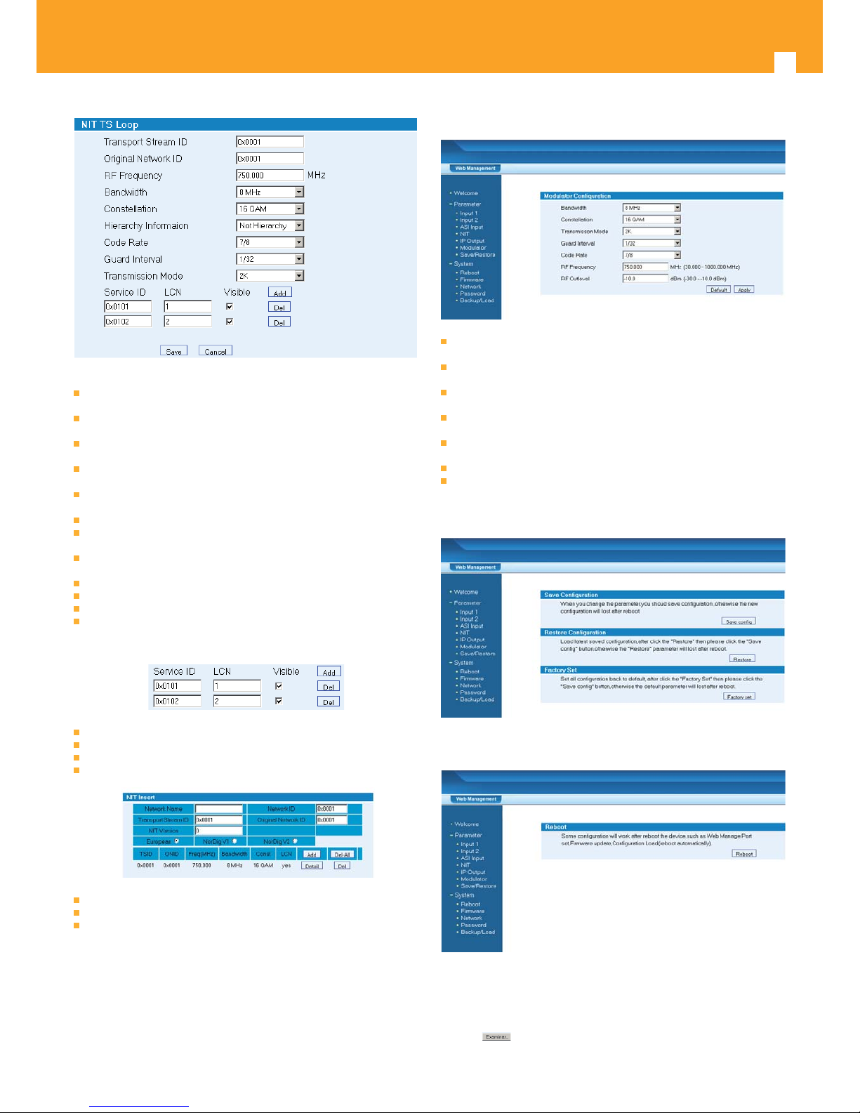
Network name: The name of current network, user can chang it as he likes.
Network ID: This is a 16-bit eld which identi es the terrestrial network that
supports the service indicated.
User can click “Add” to pop up a table, following is the interface:
Page 10
DVB-T Modulator
10
Transport stream ID: This 16-bit eld which serves as a label identifying the TS
which contains the service, event or mosaic described by the cell.
Original network ID: This is also a 16-bit eld, a label which in conjunction with
the following elds uniquely identi es a service, event or mosaic.
RF Frequency: user can set the RF frequency in this menu. The range is
30~960MHz with 1 KHz step.
Bandwidth: there are three possible options provided to be selected: 6M, 7M
and 8M.
Constellation: there also have three possible options to be selected: QPSK,
16QAM and 64QAM.
Hierarchy information: this option only adopts ISDB-T standard device.
Code rate: user can select the FEC value in the pull-down menu. There are ve
possible options provided to be chosen: 1/2, 2/3, 3/4, 5/6 and 7/8.
Guard interval: user can select the guard interval value in the pull-down
menu: 1/32, 1/16, 1/8 and 1/4.
Transmission mode: user can decide transmission mode 2k or 8k.
Service ID: unique identi er of a service within a TS
LCN: logical channel number.
Add: User can add a logical number in system by clicking “Add” menu and
typing the program information. The LCN can be added more than one by
re-clicking “Add” option. The interface shows as below:
Del: clicking “Del” to delete the added LCN information
Save: clicking “Save” to save the current NIT parameters
Cancel: clicking “Cancel” to exit the edit interface
The display will show as below when user saved the NIT settings
Update NIT: clicking to update the NIT tables in system
Save NIT: clicking to save the settings
Clear NIT: clicking to remove all the table have been inserted before
4) IP out setting
Follow the help guideline for set IP out con guration.
?????????????
5) Modulator setting
Bandwidth: there are three possible options provided to be selected: 6M, 7M
and 8M.
Constellation: there also have three possible options to be selected: QPSK,
16QAM and 64QAM.
FFT: user can set the FFT (transmission mode) by selecting in the pull-down
menu
Guard interval: user can select the guard interval value in the pull-down
menu: 1/32, 1/16, 1/8 and 1/4.
FEC: user can select the FEC value in the pull-down menu. There are ve
possible options provided to be chosen: 1/2, 2/3, 3/4, 5/6 and 7/8.
RF frequency: the range is 30~1000MHz
RF output level: the range is -30~-10dbm
6) Save/Restore
7) Reboot
8) Firmware
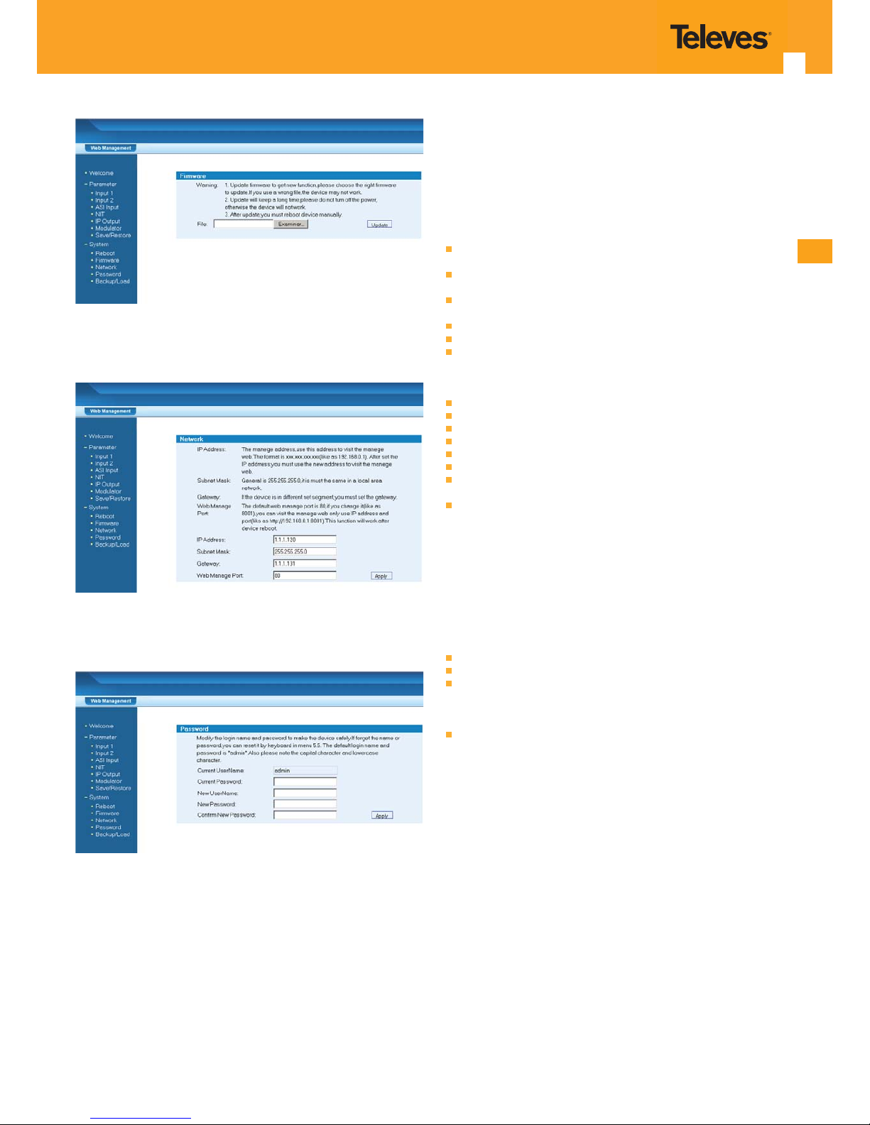
This function is used to upgrade the device’s latest software program. If
user wants to update the device to latest version, he should contact with
manufacturer to get the latest version software. When upgrading it, user can
click the “ ” button to select the program needs burned into system.
Note: User should strictly follow the “Warning” information.
Page 11
EN
11
9) Network
This interface indicates the default IP address and network mask of this device.
User can revise it and click “Apply” to con rm.
10) Password
User can revise the login password in this menu by type accordingly information
as required and click “Apply” to con rm.
Chapter 6. Troubleshooting
Televés’ ISO9001 quality assurance system has been approved by CQC
organization. For guarantee the products’ quality, reliability and stability. All
Televés products have been passed the testing and inspection before ship
out factory. The testing and inspection scheme already covers all the Optical,
Electronic and Mechanical criteria which have been published by Televés. To
prevent potential hazard, please strictly follow the operation conditions.
Prevention Measure
Installing the device at the place in which environment temperature between
0 to 45 °C
Making sure good ventilation for the heat-sink on the rear panel and other
heat-sink bores if necessary
Checking the input AC within the power supply working range and the
connection is correct before switching on device
Checking the RF output level varies within tolerant range if it is necessary
Checking all signal cables have been properly connected
Frequently switching on/o device is prohibited; the interval between every
switching on/o must greater than 10 seconds.
Conditions need to unplug power cord
Power cord or socket damaged.
Any liquid owed into device.
Any stu causes circuit short
Device in damp environment
Device was su ered from physical damage
Longtime idle.
After switching on and restoring to factory setting, device still cannot work
properly.
Maintenance needed
Chapter 7. application
7.1 Ordering guideline
Our design is individual module, for this series device the encoding module
including three version for optional:
MPEG2 SD encoding with 1 CVBS module
MPEG2 SD super encoding with 2 CVBS module
MPEG4 AVC H.264 encoding with 1 HDMI module
Modulation module including one version for optional:
DVB-T COFDM RF out module
Page 12
DVB-T Modulator
12
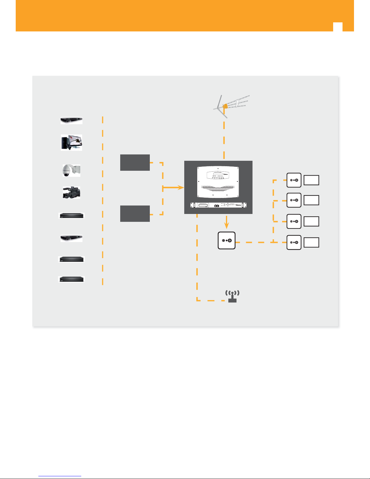
7.2 Application example
DVD
HDMI
Source
CVBS
Source
Monitor
and / or
Channel
injection
Network
Wireless router
Eventual
roof antenna
IP (optional)
Antenna
Wall socket
Camera
TV
TV
TV
TV
Advertisement
System
Blue DVD
Hard Disk Sender
Pay Channel STB
IRD STB
Page 13
EN
13
7.3 Con guration example for more than one unit in the same installation
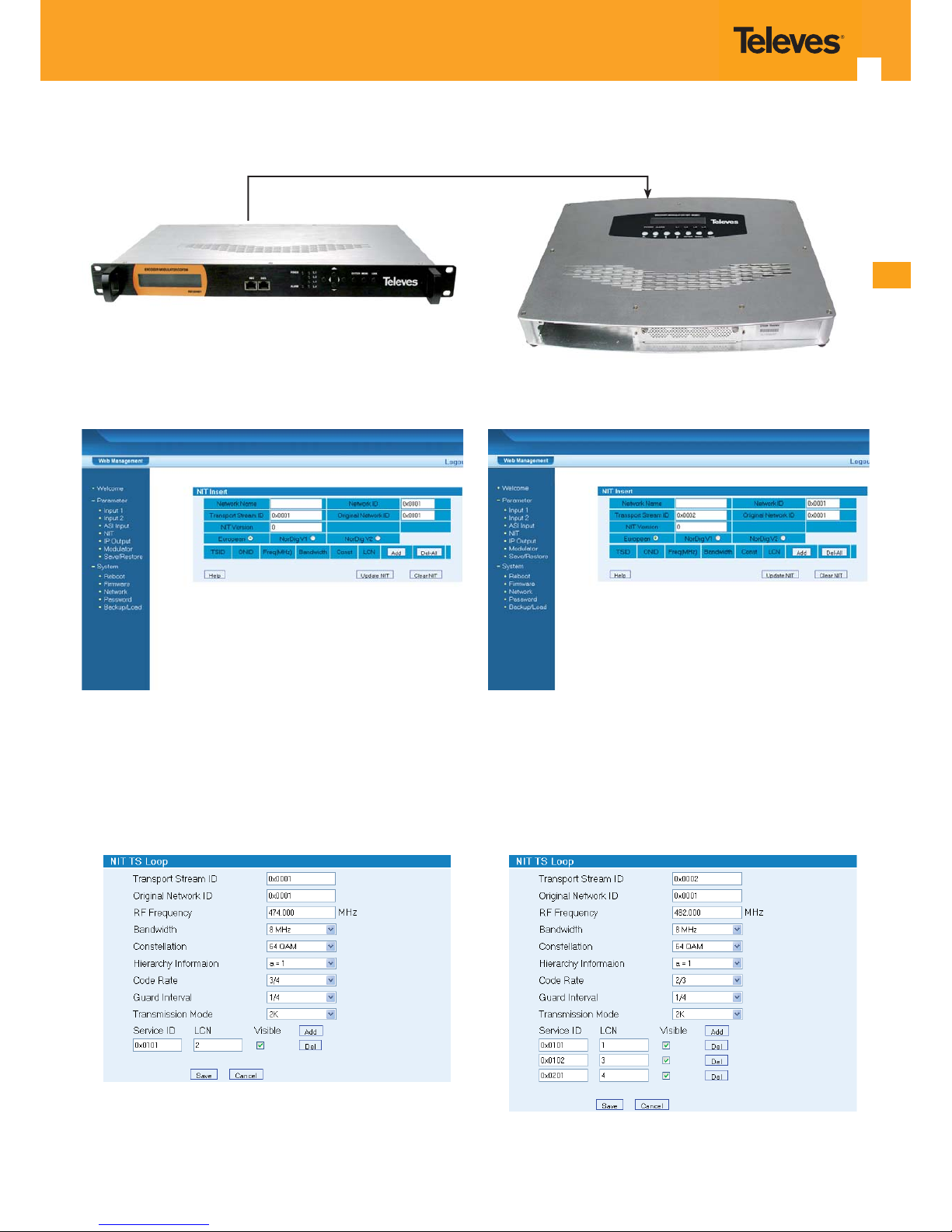
7.3.1 NIT Con guration
In this menu is possible to edit the Transport Stream ID, Original Network ID (each unit has to have a di erent TSID and ONID), assign a Network name (the same in
all units of the same network) and more. After each change is necessary to press Update NIT.
By pressing “Add” you will have access to the menu of the next images:
7.3.2 NIT, Hierarchy and LCN Con guration
In this menu is possible to edit the LCN of each program (in order to be listed correctly the Hierachy Information must be set to “a-1, a-2 or a-4”, the same on each
unit of the same network).
The LCN can be set by any order, in the image above it can be observed that the unit 2 will have program 1, 3 and 4 and unit 1 will have program 2.
Unit 1
Unit 2
Page 14
DVB-T Modulator
14
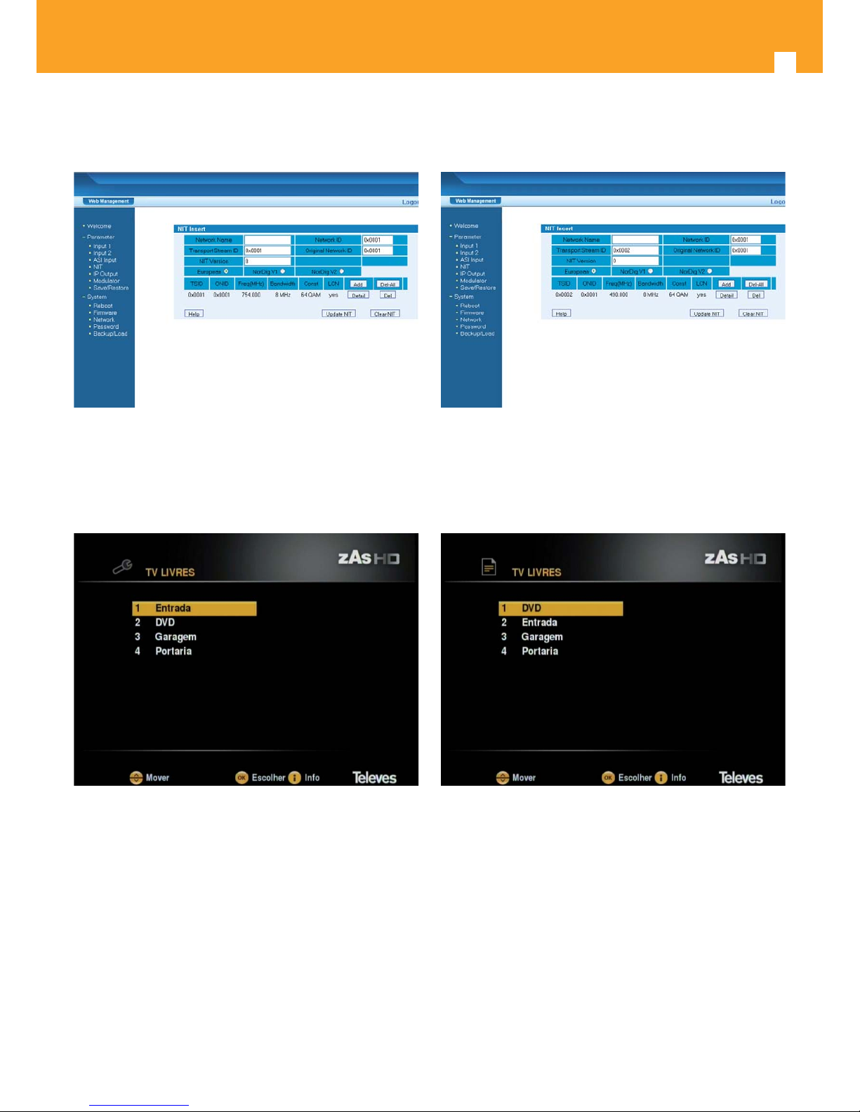
After pressing “save” on the previous menu, is necessary to press “Update NIT” again, and then in the “Save/Restore” menu press “Save con g”.
7.3.3 List Aspect on TV/Receiver
List aspect with LCN List aspect without LCN
On these two images it can be seen the two possible ways to list the programs:
• With LCN – the programs are listed in order according with the LCN con guration set above.
• Without LCN – the programs list will depend on the TV/STB and it can be based on:
- Alphabetic order
- Mux frequency
- First the HD programs, listed based on the mux frequency
- Then the SD programs, listed based on the mux frequency
Page 15

EN
15
Page 16

 Loading...