

Page 1
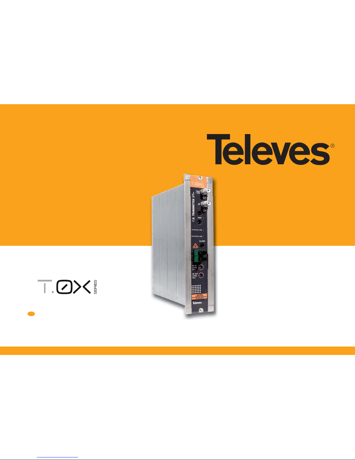
Refs. 2333, 2334
2335, 2336
www.televes.com
Optical Fiber Transmitter and Receiver
with return path channel
EN
User manual
Page 2

Page 3

ENGLISH
EN
Index
1. Technical specifi cations ...................................................................................................................... 5
2. Reference description ......................................................................................................................... 9
3. Mounting ............................................................................................................................................. 10
3.1. Wall mounting .............................................................................................................................. 10
3.2. 19” rack mounting ...................................................................................................................... 11
4. Element description ............................................................................................................................ 12
4.1. Optical transmitter ................................................................................................................... 12
4.2. Optical receiver ......................................................................................................................... 13
4.3. Power supply unit ..................................................................................................................... 14
5. Examples of application ..................................................................................................................... 15
Optical Fiber Transmitter and Receiver
Page 4
Optical Fiber Transmitter and Receiver
4
Important safety instructions:
General installation conditions:
Before handling or connecting the equipment,
please read this manual.
Do not obstruct the equipment’s ventilation
system.
Please allow air circulation around the
equipment.
Do not place the equipment near sources of heat
or in excessively moisture conditions.
Do not place the equipment where it may be
a ected by strong vibrations or knocks.
How to use the equipment safely:
If any liquid or object falls inside the equipment,
please contact a specialized technician.
Do not connect the equipment until all the other
connections have been made.
Instructions for the optical
connection:
For the optical connection, a single mode bre
cable is used with an SC/APC-type connector.
Remove the protective cover from the optical
connector on the front panel of the device, and
the cap on the connector of the single bre
cable.
Connect the cable to the device, carefully
slotting the guides together for both connectors,
pushing the connector all the way in.
Precautionary measures with the
connection point:
Take special care to avoid damaging the
unprotected ends of the connectors, as small
scratches, impurities and/or particles of dirt, oil,
grease, sweat etc. may signi cantly a ect the
quality of the signal.
To clean the ends of the connectors, gently rub
with a lint-free lens cleaning cloth, dampened
using additive-free isopropyl alcohol. Make sure
the alcohol evaporates fully before connecting.
Keep the connector covers and cable caps in a
safe place in case they are needed in the future.
Always t the covers on the connectors of devices
that are not connected to cables to prevent the
laser beam from damaging the eyes.
Avoid turning on the transmitter without having
the bre optic cable connected.
Safety measures
Warning.-
This product emits an invisible laser beam. Avoid
contact with laser radiation. The use of equipment
such as binoculars or magnifying glasses may
increase damage caused to the eyes.
LASER APERTURE
Invisible laser radiation.
Do not watch directly with
optical instruments.
Class 1M laser product.
According to EN60825-1_ 2007
Caution
- The use of controls or adjustments or any
other procedures other than those speci ed in
this manual may lead to exposure to harmful
radiation.
- Carefully read and observe the instructions given
in this manual, and keep it for future reference.
- Do not use the equipment in any way that does
not comply with the operating instructions or
in any conditions that exceed the stipulated
atmospheric speci cations.
- This equipment is not user-serviceable. Should
you require assistance, contact our technical
service department.
- Never point the laser beam intentionally at
people or animals.
Page 5
EN
5
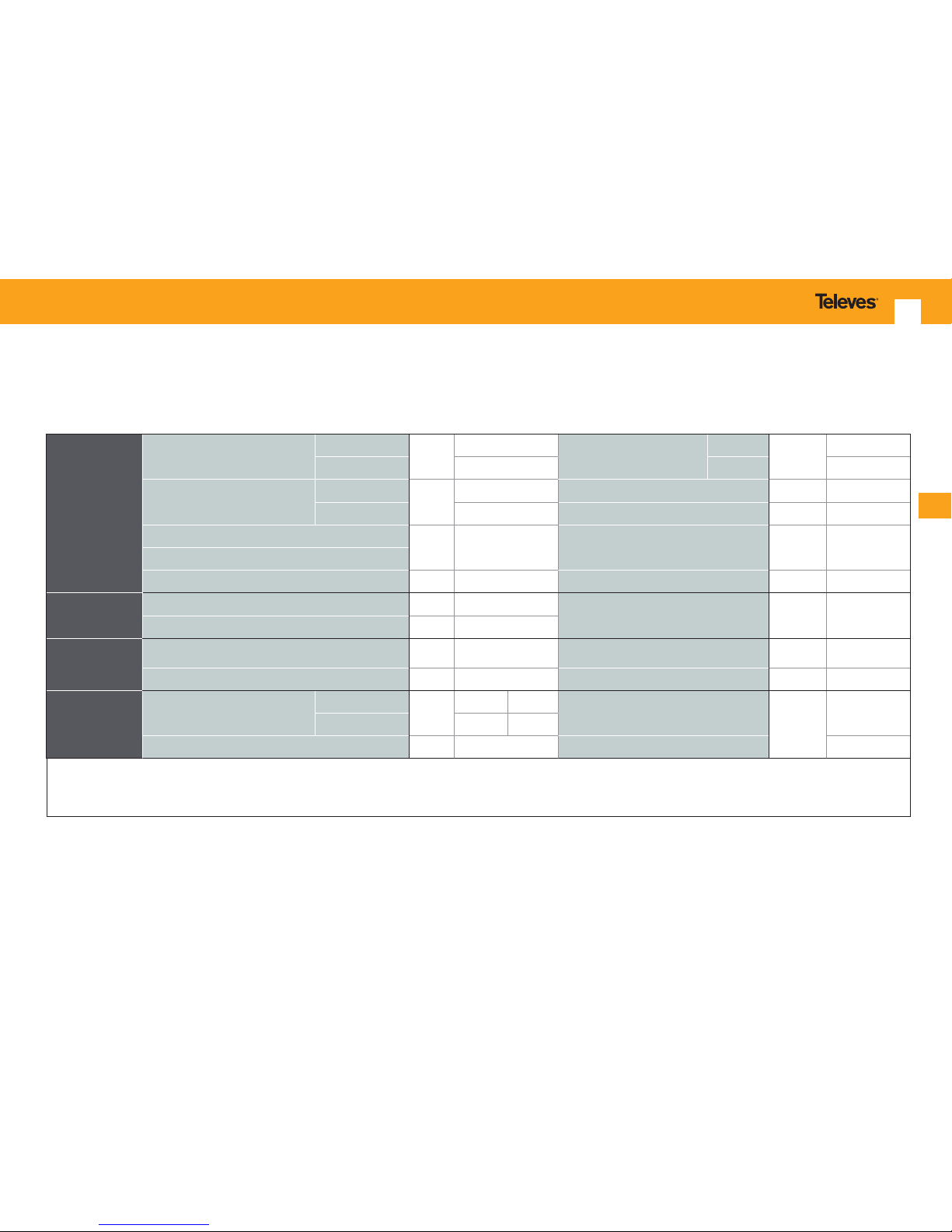
1. Technical specifi cations
Optical transmitters refs. 2333, 2334
RF
Input/Output
Frequency range
Forward channel
MHz
87 - 2150
Equivalent input noise EIN
850 MHz
dBm/Hz
-150.7
Return channel
(3)
1 - 65 2000 MHz - 145.8
Max. input level for CSO & CTB >=
60dB
(1)
)
87-862 MHz
dBμV
91 Flatness dB ± 1.5
950-2150 MHz 80 Return losses dB >= 10
Input level regulation margin (in 2 dB steps)
dB 0-18 Impedance ohm 75
Output level regulation margin (in 2 dB steps)
(3)
Return channel maximum RF output level dBμV 112
(2)
Test socket attenuation (typ.) dB 16
Optical output
(forward channel)
Laser type MQW-DFB
Output optical power mW/dBm 4 / 6
Wavelength nm 1310 ± 20
Optical input
(return channel)
(3)
Optical device type
InGaAs Pin
Photodiode
Detection bandwidth MHz 1 - 3000
Wavelength nm 1200 -1600 Max. Optical power received mW/dBm 2 / 3
General
Powering/Consumption
12 Vdc
mA
210 310
(3)
RF connectors
type
female F
24 Vdc 104 160
(3)
Operating temperature ºC -5 ··· +45 Optical connectors SC/APC
(1) I nput: 41 T V CH CENELEC and 1complete satellite transponder. The input attenuator in 0dB position.
(2) M easurement made according to standard DIN45004B.
(3) Only ref. 2334.
Page 6
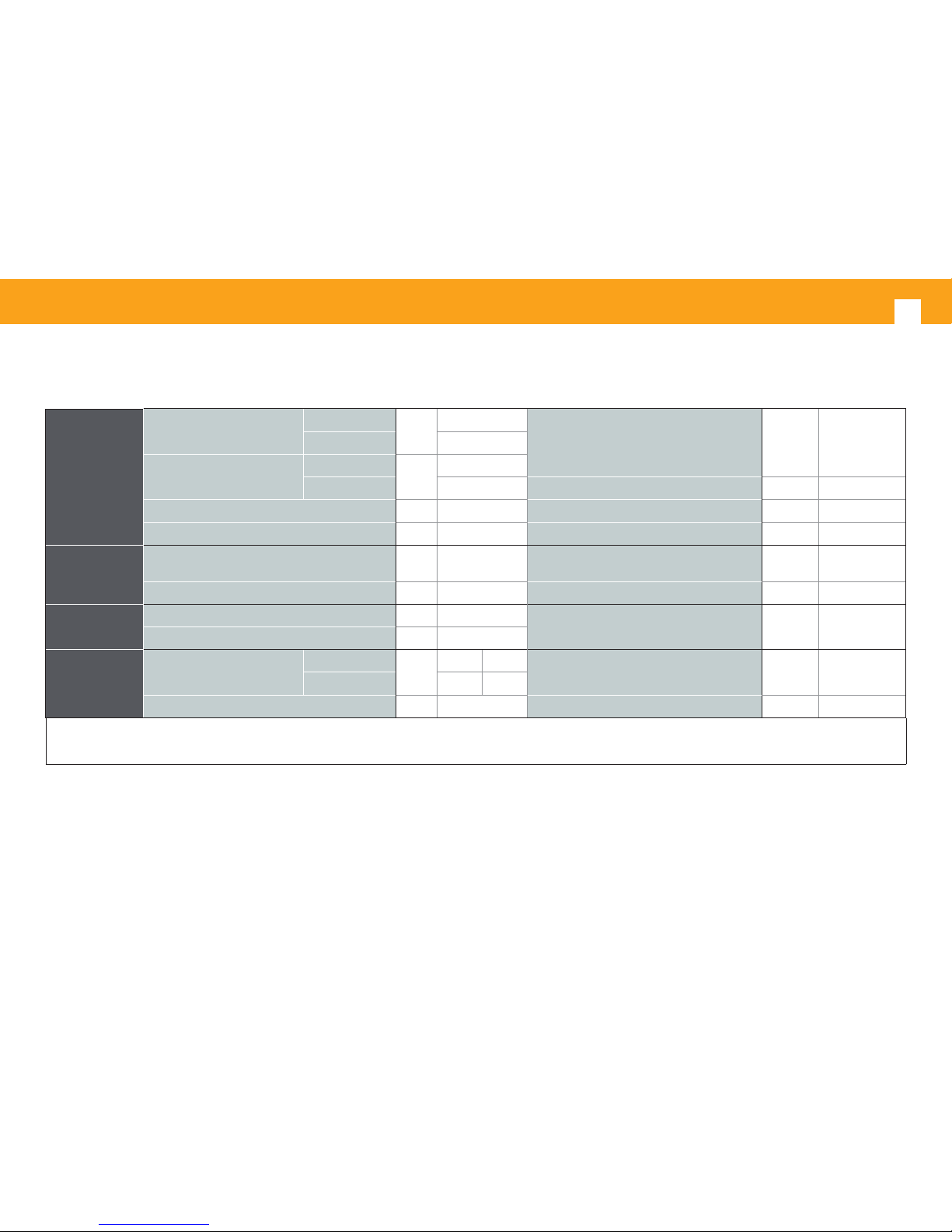
Optical Fiber Transmitter and Receiver
6
RF
Input/Output
Frequency range
Forward channel
MHz
87 ··· 2150
Equivalent input noise of the return channel,
measured at 30 MHz and the transmitter
output connected directly to the receiver
dBm/Hz -152.5Return channel
(3)
1 ··· 65
Max. Output Level for CSO and
CTB> = 60dB
(1)
)
87-862 MHz
dBμV
93
950-2150 MHz 90 Flatness dB ± 1.5
Output level regulation margin (in 2 dB steps) dB 0-18 Return losses dB >= 11
Max. input level return path
(2) (3)
dBμV 95
Impedance ohm 75
Optical input
(forward channel)
Optical device type
InGaAs Pin
Photodiode
Detection bandwidth MHz 1 ··· 3000
Wavelength nm 1200 ··· 1600 Max. Optical power received mW/dBm 4 / 6
Optical output
(return channel)
(3)
Laser type Fabry-Perot
Maximum ouitput power mW/dBm 2 / 3
Wavelength nm 1310±20
General
Powering/Consumption
12 Vdc
mA
300 355
(3)
RF connectors type female F
24 Vdc 155 175
(3)
Operating temperature ºC -5 ··· +45 Optical connectors SC/APC
(1) Output: 42 TV CH CENELEC and 1 complete satellite transponder. The output attenuator in 0dB position.
(2) According to DIN45004B
(3) Only ref. 2336
Optical receivers refs. 2335, 2336
Page 7
EN
7
Ampli er
5575
Frequency range 46 ... 862 MHz Connector type “F”
Gain 44 ± 2,5 dB Powering 24 V
Regulation margin 20 dB Consumption at 24 V : 450 mA
Output level (at 60 dBc): 105 dBμV (42 CH CENELEC) Test socket -30 dB
Power Supply Unit
5629
Mains voltage 196 - 264 V~ 50/60 Hz
Total max. current
(output1 + output2):
5 A (24V )
Output voltage 24V
Max. current per output 4 A (24V )
1.5. Ampli ers technical speci cations
1.6. Technical specs. Power Supply Unit
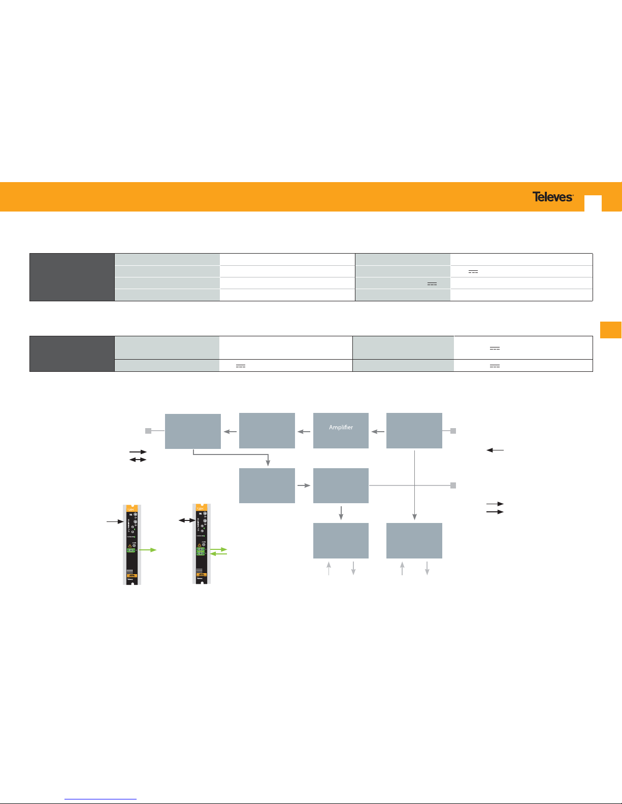
1.7. Blocks diagrams
Diplexer
Fwd path / Rtn
path
RF INPUT
(forward path)
RF OUTPUT
(return path
ref. 2333
ref. 2334
Attenuator
Forward path
Converter
RF Æ FO
Forward path
Control
LED Relay
Attenuator
Return path Return path
Converter
RF Å FO
FO INPUT
Return path
Return path
Control
LED Relay
FO OUTPUT
ref. 2333
ref. 2334
Forward path
ref. 2334
2333
PWR
2334
PWR
Page 8
Optical Fiber Transmitter and Receiver
8
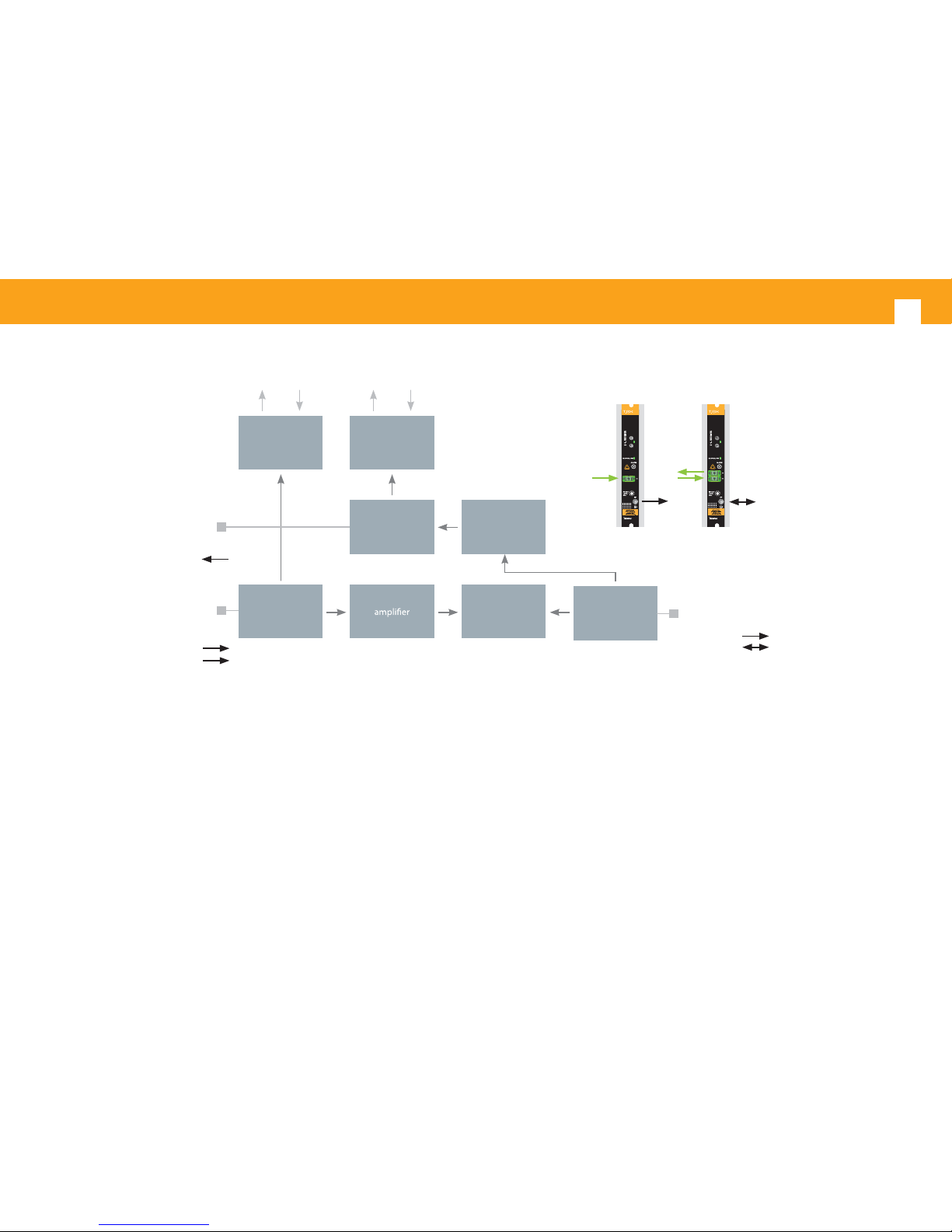
Diplexer
Fwd path / Rtn path
RF OUTPUT Fwd path
RF INPUT Rtn path
Return path
attenuator
Converter
RF Å FO
Return path
control
LED
Relay
Forward path
attenuator
Forward path
Æ
Converter
FO Æ RF
FO OUTPUT
Return path
ref. 2336
ref. 2335
ref. 2336
Forward path
control
LED
Relay
FO INPUT
Forward path
2335
PWR
2336
PWR
ref. 2335
ref. 2336
Page 9

EN
9
2. Description of references
Product range
2333 T.0X Optical ber transmitter 1310 nm
2334 T.0X Optical ber transmitter 1310 nm + Return channel receiver
2335 T.0X Optical ber receiver 1200-1600 nm
2336 T.0X Optical ber receiver + Return channel transmitter
2337 T.0X 2 way optical splitter
2339 T.0X 4 way optical splitter
5629 T.0X Power Supply Unit 24V/5A
Accessoires
7234 Universal programmer
5071 Wall mounting rail T03-T05-T.0X L=50 cm
5239 Wall mounting rail T03-T05-T.0X (12 modules +PSU) L= 56 cm
5301 19” rack frame
507202 T.0X cabinet with ventilation unit (7 modules + PSU)
4061 F terminal load DC-blocked
4058 F terminal load
422601 T05 to T.0X powering adapter lead L=40 cm
422602 T05 to T.0X BUS adapter lead L=40 cm
422603 Control BUS lead T.0X L=1 m
5673 Face plate 50 mm
Page 10
Optical Fiber Transmitter and Receiver
10
UQQA-S2-T
DVBS 2-QAM TWIN
UQQA-S2-T
DVBS 2-QAM TWIN
UQQA-S2-T
DVBS 2-QAM TWIN
UQQA-S2-T
DVBS 2-QAM TWIN
UQQA-S2-T
DVBS 2-QAM TWIN
UQQA-S2-T
DVBS 2-QAM TWIN
F. O. TRANSMITTER
T
E
S
T
(-
1
2
d
B
)
R
F
T
X
O
P
T
I
C
A
L
P
W
R
R
F
IN
L
E
V
E
L
A
D
J
.
A
L
A
R
M
0
2
4
6
8
1
0
12
14
16
18
P
W
R
T
X
L
A
S
E
R
A
P
E
R
T
U
R
E
I
n
v
i
s
i
b
l
e
l
a
s
e
r
r
a
d
i
a
t
i
o
n
.
D
o
n
o
t
w
a
t
c
h
d
i
r
e
c
t
l
y
w
i
t
h
o
p
t
i
c
a
l
i
n
s
t
r
u
m
e
n
t
s
.
C
l
a
s
s
1
M
l
a
s
e
r
p
r
o
d
u
c
t
.
1
2
CLAC!
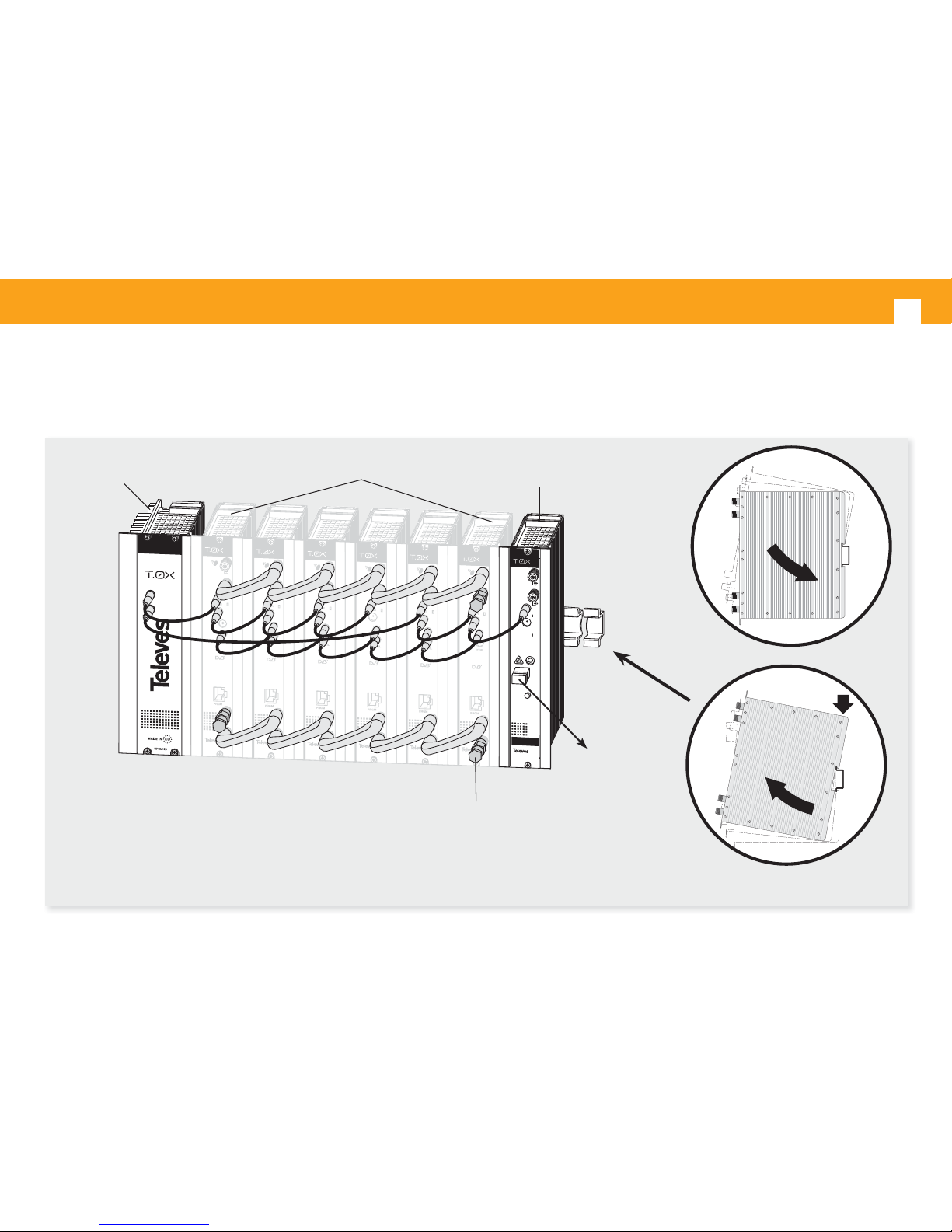
3. Mounting
3.1. Wall mounting
NOTE: We recommend using both outputs of the source, balancing consumption.
F.O. transmitter
4061
5071
5239
T.0X Headend
5629
Optical
output
Page 11
EN
11
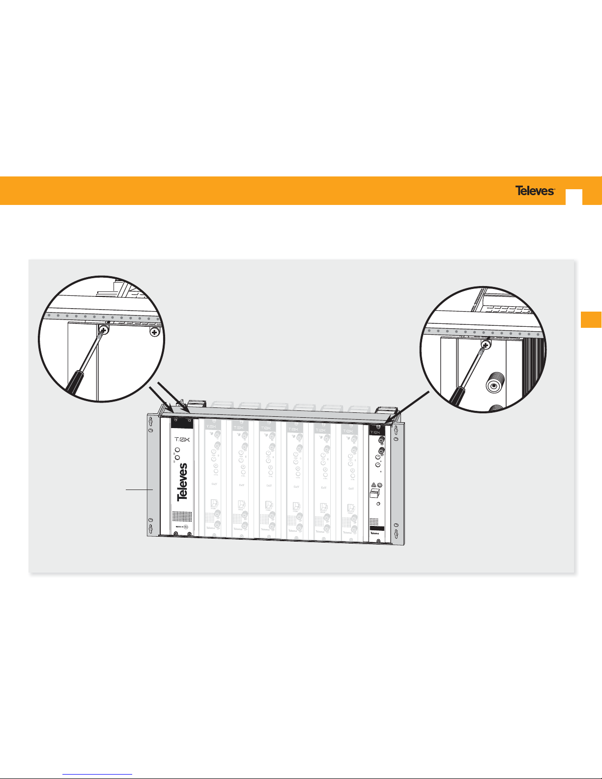
3.2. 19” rack mounting
U
P
S
U
1
2
0
UQQA-S2-T
DVBS 2-QAM TWIN
UQQA-S2-T
DVBS 2-QAM TWIN
UQQA-S2-T
DVBS 2-QAM TWIN
UQQA-S2-T
DVBS 2-QAM TWIN
UQQA-S2-T
DVBS 2-QAM TWIN
UQQA-S2-T
DVBS 2-QAM TWIN
F. O. TRANSMITTER
TEST
(-1
2
d
B
)
RF
T
X
O
P
T
IC
A
L
P
W
R
RF IN
LEVEL
ADJ.
ALARM
0
2
4
6
8
1
0
1
2
1
4
1
6
1
8
PWR
T
X
LASER APE
RT
URE
In
visib
le la
ser radiation.
D
o not w
atch d
ire
ctly w
ith op
tical in
strum
ents.
Cla
ss 1M
laser pro
duct.
5301
Page 12
Optical Fiber Transmitter and Receiver
12
4. Description of elements
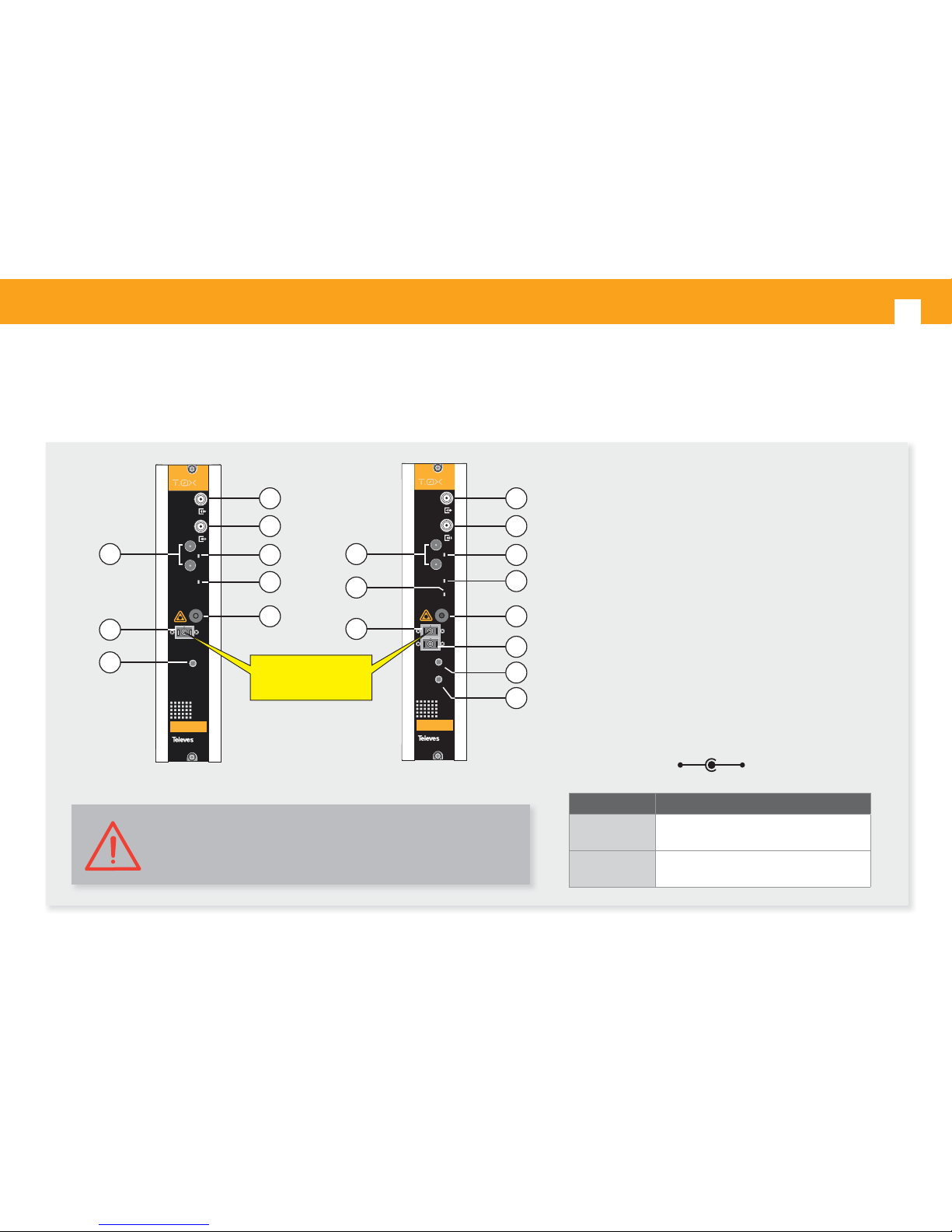
4.1. Optical transmitter
02340088 000
F. O. TRANSMITTER
TEST
(-12dB)
RF
TX OPTICAL PWR
RF IN
LEVEL
ADJ.
ALARM
0
2
4
6
8
1
0
12
1
4
1
6
18
PWR
TX
LASER APERTURE
Invisible laser radiation.
Do not watch directly with optical instruments.
Class 1M laser product.
02340089 000
F.O. TRANSMITTER
TEST
(-12dB)
RF
TX OPTICAL PWR
RF IN
LEVEL
ADJ.
ALARM
0
2
4
6
8
1
0
12
14
16
1
8
PWR
RX OPTICAL PWR
RF OUT
LEVEL
ADJ.
0
2
4
6
8
1
0
12
14
16
1
8
TX
RX
with RX
return path
LASER APERTURE
Invisible laser radiation.
Do not watch directly with optical instruments.
Class 1M laser product.
1
2
4
3
5
7
9
6
8
10
1
2
4
3
5
7
8
10
11
LASER APERTURE
CLASS 1M LASER
1. Test output (-16dB)
2. RF Input
87 - 2150 MHz (forward channel)
5 - 65 MHz (return channel)
3. Powering
4. ON power indicator LED
5. Forward channel power indicator LED
6. Return channel power indicator LED
7. Alarm connector
8. Forward channel optical output
9. Return channel optical input
10. Forward channel RF attenuation
11. Return channel RF attenuation
Caution
The use of control or adjustment devices, or operating parameters
other than those speci ed in this manual, can cause hazardous
radiation exposure.
Ref. 2333 Ref. 2334
LED ON Indicates
TX Optical PW
Optical power delivered by the equipment
from 5.5 dBm to 6.5 dBm
RX Optical PW
Optical level received by the return channel
from 3 dBm to -7 dBm.
Masa +12 ... 24V
Page 13
EN
13
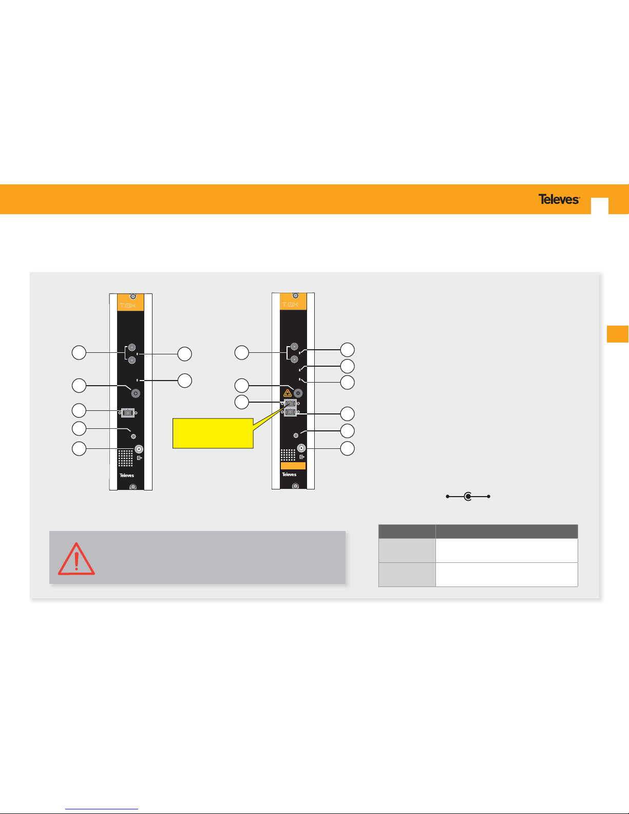
4.2. Optical receiver
1. Powering
2. ON power indicator LED
3. Forward channel power indicator LED
4. Return channel power indicator LED
5. Alarm connector
6. Forward channel optical output
7. Return channel optical input
8. Return channel attenuation
9. RF output
87 - 2150 MHz (forward channel)
5 - 65 MHz (return channel)
Caution
The use of control or adjustment devices, or operating parameters
other than those speci ed in this manual, can cause hazardous
radiation exposure.
F.O. RECEIVER
RF
TX OPTICAL PWR
RF OUT
LEVEL
ADJ.
ALARM
0
2
4
6
8
1
0
1
2
14
16
1
8
PWR
RX OPTICAL PWR
TX
RX
with TX
return path
LASER APERTURE
Invisible laser radiation.
Do not watch directly with optical instruments.
Class 1M laser product.
F. O. RECEIVER
RF
RX OPTICAL PWR
RF OUT
LEVEL
ADJ.
ALARM
0
2
4
6
8
10
12
14
16
18
PWR
RX
2
1
4
7
6
8
2
1
9
3
5
4
5
LASER APERTURE
CLASS 1M LASER
8
9
7
Ref. 2335 Ref. 2336
LED ON Indicates
RX Optical PW
Input optical power on the device from 5
dBm and -10 dBm.
TX Optical PW
Optical level broadcast on the return channel between 2.5 dBm and 3.5 dBm.
Masa +12 ... 24V
Page 14
Optical Fiber Transmitter and Receiver
14
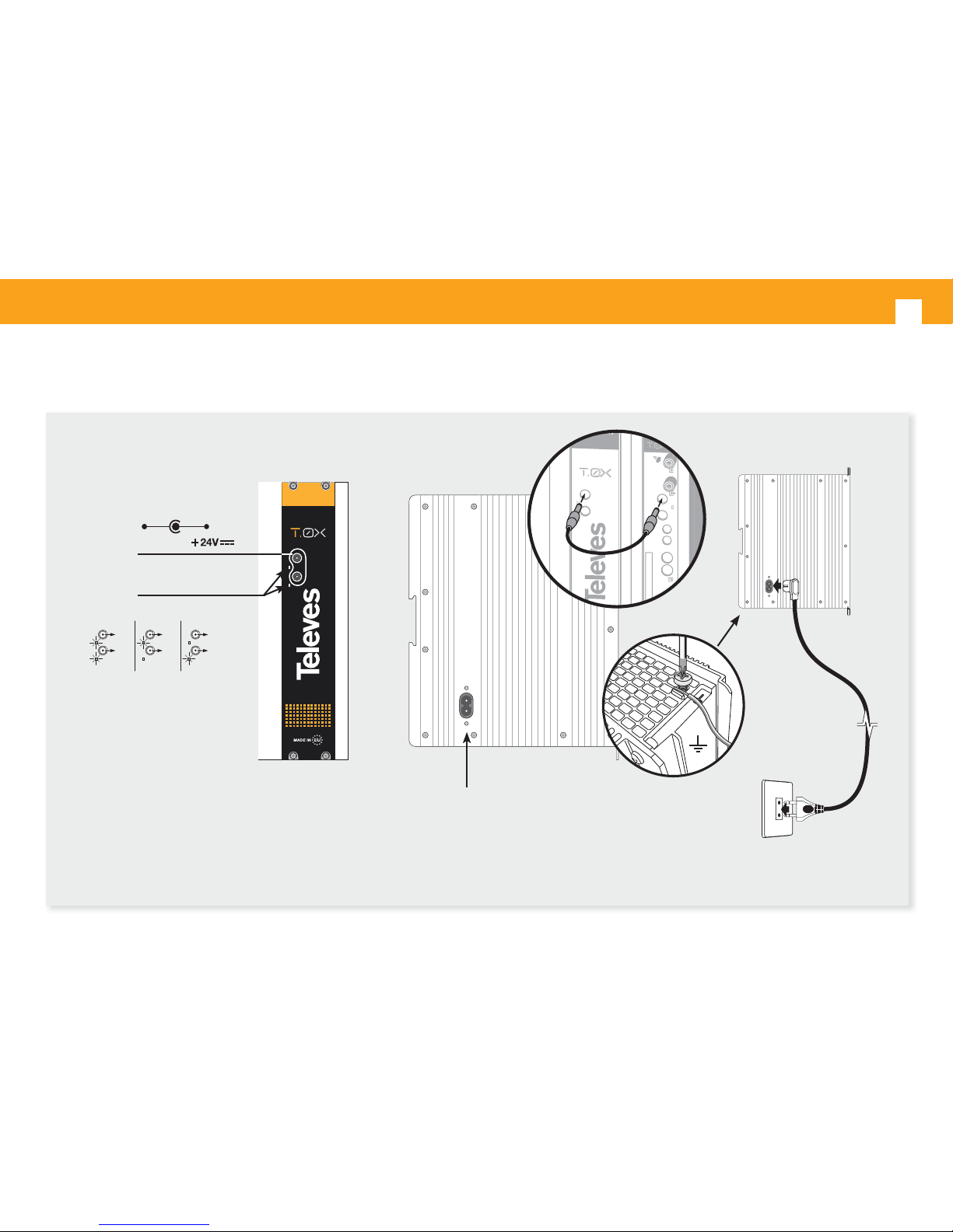
4.3. Power Supply Unit
Input power
connectors (1)
Status LED
(1)
Mains input
230V~
UPSU120
U
Q
P-C
I-T
CTRL
A
B
QPSK-PAL CI TWIN
PWR
A/V
NOTE: You must use both outputs of the source when consumption exceeds 4 amps on either of them (maximum current for each output)
24V: OK
0V: Overloading or shortcircuiting
24V
24V
24V
0V
0V
24V
Masa
Page 15
EN
15
5. Examples of application
Correct use of the devices.
There are several basic concepts that should not be
forgotten. The technical speci cations are a set of
maximums to be handled with some care.
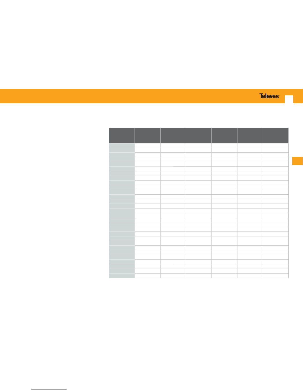
To calculate the RF level which must excite the
transmitter, use the data in the table shown below
and the following formulas:
EIN= EINn +10×log(BW) [1]
C/N=Vin - EIN [2]
where:
• EIN is the equivalent input noise. That is, the
noise in RF, which would have to be present
at the input of the transmitter in an ideal
optic system that did not add noise, so as to
obtain the same level of noise at the output
of the receiver of the real system (It always
add noise).
• EINn is the EIN for a bandwidth of 1Hz.
• BW is the bandwidth of the RF signal.
• Vin is the RF input level, and is given in dBm.
Here are some examples.
Opt. Link
atenuattion
(dB)
Gain
at 807 MHz
(dB)
EINn
(dBm/Hz)
Gain
at 1.2 GHz
(dB)
EINn
(dBm/Hz)
Gain
at 2.1 GHz
(dB)
EINn
(dBm/Hz)
0 16.2 -150.4 17.0 -150.4 17.4 -146.4
2 12.3 -148.4 13.13 -148.9 13.4 -145.7
4 8.7 -146.6 9.4 -147.0 9.7 -144.9
4.5 7.7 -145.85 8.4 -146.3 8.7 -144.6
5 6.6 -144.9 7.4 -145.6 7.7 -144.2
5.5 5.6 -144.1 6.4 -144.8 6.7 -143.7
6 4.6 -143.3 5.4 -144.1 5.7 -143.2
6.5 3.6 -142.5 4.4 -143.2 4.7 -142.7
7 2.6 -141.6 3.4 -142.4 3.7 -142.1
7.5 1.6 -140.8 2.4 -141.6 2.7 -141.5
8 0.6 -139.9 1.4 -140.7 1.7 -140.8
8.5 -0.3 -139.1 0.4 -139.8 0.7 -140.1
9 -1.3 -138.2 -0.5 -139.1 -0.3 -139.4
9.5 -2.3 -137.25 -1.5 -138.1 -1.3 -138.7
10 -3.3 -136.35 -2.5 -137.2 -2.2 -138.0
10.5 -4.3 -135.4 -3.5 -136.3 -3.2 -137.2
11 -5.3 -134.5 -4.5 -135.5 -4.3 -136.3
11.5 -6.3 -133.5 -5.5 -134.47 -5.3 -135.5
12 -7.3 -132.55 -6.5 -133.5 -6.3 -134.6
12.5 -8.3 -131.6 -7.5 -132.57 -7.3 -133.7
13 -9.3 -130.6 -8.5 -131.6 -8.3 -132.8
13.5 -10.3 -129.7 -9.5 -130.65 -9.3 -131.9
14 -11.3 -128.7 -10.5 -129.67 -10.3 -131.0
14.5 -12.3 -127.7 -11.5 -128.7 -11.3 -130.1
15 -13.3 -126.7 -12.5 -127.7 -12.3 -129.2
15.5 -14.3 -125.8 -13.5 -126.7 -13.3 -128.2
16 -15.3 -124.8 -14.5 -125.7 -14.3 -127.3
16.5 -16.3 -123.8 -15.5 -124.8 -15.3 -126.3
17 -17.3 -122.8 -16.5 -123.8 -16.3 -125.4
Measurements made with a transmitter that delivers 6.1 dBm, followed by a reel of ber of 5 km long and an optical attenuator
connected between the end of the reel of ber and optical receiver input.
Page 16
Optical Fiber Transmitter and Receiver
16
link in the value of 0.6 dB, which would correspond
EINn =-139.9 dB/Hz.
Apply the formula [1] and we obtain:
EIN
TV
= -139.9 + 10×log(5×10⁶)= -72.91 dBm
Now apply the formula [2] to calculate the C/N, as
follows:
C/N
TV
=Vin - EIN
TV
C/NTV = -26 dBm -(- 65.7 dBm) = -26+65.7
Then, C/N
TV
= 46.9 dB
In practice, having satellite channels,
simultaneously with the TV ones, makes the latter
worse their C/N in 1 dB.
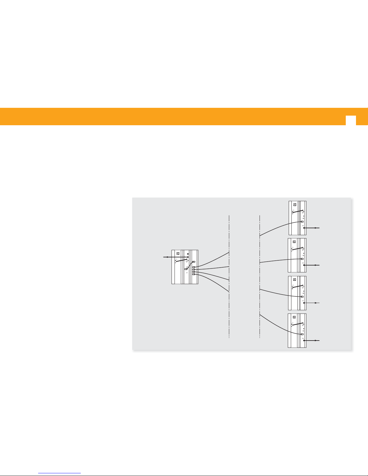
Example 1
Calculate the C / N at the output of the optical
receiver (C/N of the link), in the installation of the
gure below:
This is a link where the optical signal is split
between 4 bers of 1 km, using a splitter ref. 2339.
The signal received at the other end is converted
back to RF by means of the optical receiver ref.
2335.
The channel levels that excite the transmitter are:
- 83 dBμV (-26 dBm 42CH CENELEC) analog
channels, TV band.
- 73 dBμV (-36 dBm) digitales channels, SAT band.
Analog terrestrial channel bandwidth: 5 MHz
Satellite digital transponder bandwidth: 27 MHz
On the other hand:
• 1 km optical ber is equivalent to 0.4 dB of
attenuation.
• The splitter features 6.8 dB loss.
• The 2 ber optic connectors represent 0.8 dB (2
× 0.4).
Therefore, total losses of the optical ber link are:
FO losses+Optical splitter losses+Connectors losses
This is: 0.4 + 6.8 + 0.8 = 8 dB
Now we use the formulas and data given in the
table above.
For the TV band, we consider the column of the
Gain at 807 MHz. This column intersects with the
row of 8 dB of loss calculated for the optical ber
F. O. RECEIVER
F. O. TRANSMITTER
F. O. SPLITTER 1/4
F. O. RECEIVERF. O. RECEIVERF. O. RECEIVER
INPUT
signal
TV + SAT
RF signal
TV + SAT
1 Km
RF signal
TV + SAT
RF signal
TV + SAT
RF signal
TV + SAT
(1)
(2)
(4)
(3)
Page 17
EN
17
For the TV band, in the column Gain at 807 MHz
EINn (TV)= -122.8 dBm/Hz
G(807 MHz)= -17.3 dB
And for SAT band, look in the Gain at 2.1 GHz
column.
EINn(SAT) = -125.4 dBm/Hz
• The 2 ber optic connectors represent 0.8 dB.
Therefore, the total losses of the ber optics are:
0.4 + 16 + 0.8 = 17.2 dB
(let’s take 17 dB for this case, maximum value
shown in the table)
The table provides the following information:
Now we do the calculation for digital satellite
channels, following the same process above, but
by looking at the column Gain at 2 .1 GHz of the
table (band in which are delivered digital channels)
and the following results :
EINn= -140.8 dB/Hz
EIN
SAT
= -140.8 + 10×log(27×106) = - 65.7 dBm
As the input level is -36 dBm, C/N is:
C/N
SAT
= -36-(-65.7) = -36 + 65.7
C/N
SAT
= 29.7 dB
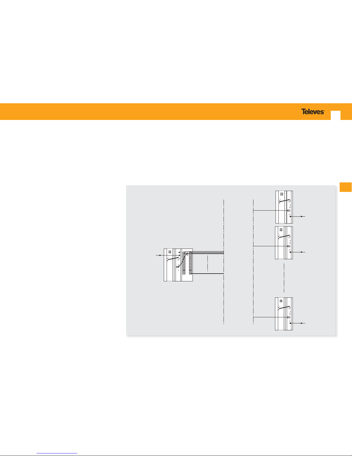
Example 2
Let’s repeat the example above but applied to an
installation with a 32 output optical splitter. The
channels will be digital only.
Thus, the TV channels will be COFDM channels
with a C/N
COFDM
= 23 dB.
SAT channels will be DVB-S2, with a
C/N
DVBS2
= 14 dB.
The level of excitation of the transmitter will be
the same for TV and SAT: 79 dBµV (-30dBm).
The bandwidth will be now:
For COFDM: BW = 8×10
6
Hz (8 MHz)
For SAT: BW = 27×10
6
Hz (27 MHz)
As in Example 1, the attenuations are:
• 1 km of ber is 0.4 dB.
• The 32 output optical splitter represents about
16 dB
F. O. SPLITTER 1/32
F. O. RECEIVER
F. O. TRANSMITTER
F. O. RECEIVERF. O. RECEIVER
INPUT
signal
TV + SAT
RF signal
TV + SAT
(1)
(2)
(32)
1 Km
RF signal
TV + SAT
RF signal
TV + SAT
Page 18
Optical Fiber Transmitter and Receiver
18
RETURN CHANNEL
For the return channel transmitter, the table of
attenuations, link gain and equivalent noise is:
Link attenuation
(dB)
Gain at 30 MHz
(dB)
EINn
(dBm/Hz)
0 23 -152.5
3 16.6 -149.5
4 14.6 -147.6
5 12.7 -145.7
6 10.7 -143.9
7 8.7 -141.9
8 6.7 -140
9 4.7 -138.1
10 2.6 -136
11 0.4 -133.4
12 -1.5 -132
13 -3.5 -130.5
14 -5.5 -128.5
Measurements made with a transmitter that delivers 2.9dBm
followed by an optical attenuator connected between the
transmitter and the optical receiver.
Use the formulas 1 and 2 for making calculations.
The calculation process is the same as in the case
of the forward channel.
G(2.1 GHz)= -16.3 dB
Therefore, the RF signal level delivered by the
receiver is:
Vout
rcvr
(dBμV) = Vin
xmtr
(dBμV) + G (dB)
This is:
V
out rcvr
TERR
(dBμV) = 79 -17.3 = 61.7 dBμV
V
out rcvr
SAT
(dBμV) = 79 -16.3 = 62.7 dBμV
Applying the formula [1]:
EIN
TV
= EINn(TV) + 10×log(8×10⁶) [dBm]
EIN
TV
= -122.8 + 69
EIN
TV
= -53.8 dBm
And by the formula [2] is obtained:
C/N
TV
= - 30 dBm - (- 53.8 dBm) = 23.8 dB en TV
Likewise, we calculate the C/N for SAT channels,
resulting in:
EIN
SAT
= - 51.1 dBm
C/N
SAT
= -30 - (-51.1) = 21.1 dB en SAT
If we estimate the value of the C / N for TV very
tight, you can increase the excitement level of the
transmitter a couple of dB, since there is enough
margin before the system
begins to distort.
Page 19
EN
19
Guarantee
Televés S.A. offers a two year guarantee, beginning from the date of
purchase for countries in the EU. For countries that are not part of the EU,
the legal guarantee that is in force at the time of purchase is applied. Keep
the purchase invoice to determine this date.
During the guarantee period, Televés S.A. complies with the guarantee by
repairing or substituting the faulty equipment.
The harm produced by improper usage, wear and tear, manipulation by a
third party, catastrophes or any other cause beyond the control of Televés
S.A. is not included in the guarantee.
Page 20

 Loading...