

Page 1
SUNSTAR传感与控制 http://www.sensor-ic.com/ TEL:0755-83376549 FAX:0755-83376182 E-MAIL:[email protected]
SUNSTAR传感与控制 http://www.sensor-ic.com/ TEL:0755-83376549 FAX:0755-83376182 E-MAIL:[email protected]
VACUGUARD USER’S GUIDE
PORTABLE VACUUM MEASUREMENT
TELEVAC
A DIVISION OF THE FREDERICKS COMPANY
2400 PHILMONT AVENUE,
HUNTINGDONVALLEY, PA 19006
Page 2

SUNSTAR传感与控制 http://www.sensor-ic.com/ TEL:0755-83376549 FAX:0755-83376182 E-MAIL:[email protected]
SUNSTAR传感与控制 http://www.sensor-ic.com/ TEL:0755-83376549 FAX:0755-83376182 E-MAIL:[email protected]
TABLE OF CONTENTS
SECTION & TITLE
01. DESCRIPTION
02. SAFETY INSTRUCTIONS
03. INSTALL THE BATTERY
04. INSTALL THE CABLE (S)
05. TEST YOUR VACUGUARD / DISPLAY UNITS
06. USEFUL INFORMATION
07. TROUBLESHOOTING
08. SPECIFICATIONS
09. UNPACKING & INSPECTION
10. WARRANTY INFORMATION
PLEASE READ THIS MANUAL THOROUGHLY BEFORE USING THIS
INSTRUMENT. REPORT ANY PROBLEMS IMMEDIATELY.
Page 3

Wireless Portability : A replaceable “D” cell eliminates 110VAC extension cords
Rugged Const r uction: Powder coated extruded aluminum enclosure and an
Large Digital Display: Bright red LED display won’t wash out in direct sunlight.
Display reads in Torr or Millitorr, as appropriate to sensor type
Pos ition switch permit s re ading Tel e vac 2A/ 2A Mi ni or DV4 and DV6 sensors.
SUNSTAR传感与控制 http://www.sensor-ic.com/ TEL:0755-83376549 FAX:0755-83376182 E-MAIL:[email protected]
SUNSTAR传感与控制 http://www.sensor-ic.com/ TEL:0755-83376549 FAX:0755-83376182 E-MAIL:[email protected]
CHAPTER 1 TELEVAC
Description
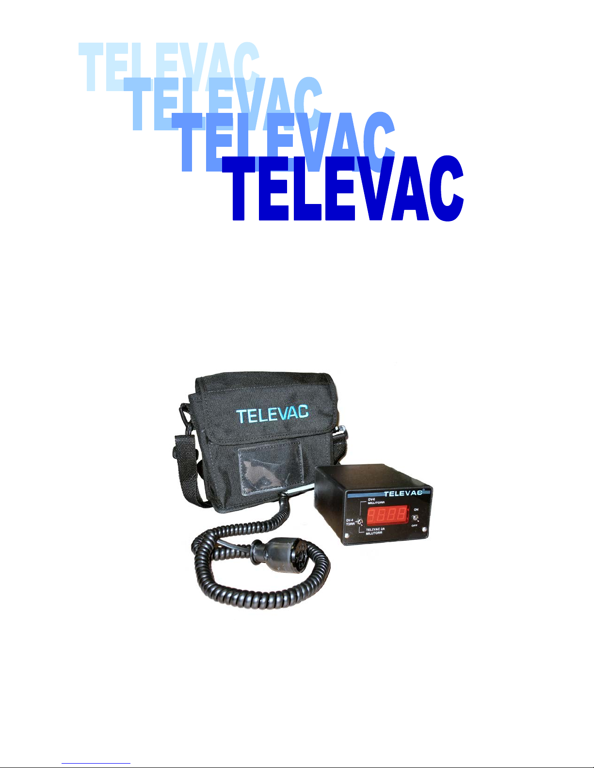
The VacuGuard is a small, self-contained instrument, designed to power and read
Televac 2A series or competitor compatible DV4 and DV6 series thermocouple sensors.
The VacuGuard is powered by a 1.5V ‘D’ cell and will accept either single use or
rechargeable ‘D’ cells. Front panel controls consist of a toggle power switch and a thre eposition sensor select switch. The digital displa y is a four digit; seven segment re d LED,
0.6” high, protected by a red neutral density filter that permits use in bright ambient
conditions. The instrument reads directly in torr or millitorr. Overall size is:
4”x2.5”x5.5”. Instrume nt weight i s 23 oz.
FEATURES
and their associated safety hazards.
available hands-free carry i ng cas e w ill go the distance for years of productive service.
Page 4
CHAPTER 2 TELEVAC
These safet y a le rt sy mb ols in this manual or on the Product rear panel mean
Failure to comply with these instructions may result in serious personal injury, including
SUNSTAR传感与控制 http://www.sensor-ic.com/ TEL:0755-83376549 FAX:0755-83376182 E-MAIL:[email protected]
SUNSTAR传感与控制 http://www.sensor-ic.com/ TEL:0755-83376549 FAX:0755-83376182 E-MAIL:[email protected]
Safety Instructions
START BY READING THESE IMPORTANT SAFETY INSTRUCTIONS AND
NOTES collected here for your convenience and repeated with additional information at
appropriate points in these instructions.
In these instructions the word “product” refers to the MV2A and a ll of it s ap prove d pa rts
and accessories.
NOTE: These instructions do not and cannot provide for every contingency that
may arise in connection with the installation, operation, or maintenance of this
product. Should you require further assistance, please contact Televac at the
address on the title page of this manual.
This product has be e n designed and tested to offe r r e asonably safe service provided in it’s
installed, operated and serviced in strict accordance with these safety instructions.
death, or property damage.
These safety precautions must be observed during all phases of operation,
installation, and service of this product.
Failure to comply with these precautions or with specific warnings elsewhere in
this manual violates safety standards of design, manufacture, and intended use of
the instrument. Televac disclaims all li ability for the cu stomer’s failure to compl y
with these requirements.
cautions - personal safety, property damage or danger from electrical shock. Read these
instructions carefully.
Page 5
CHAPTER 2 (cont.) TELEVAC
The service and repair information in this manual is fo r the use of Qualified Service
Servicing on this product unless you are qualified to do so.
Objects and Liquid Entry – N ever push objects of any kind into t his product throu gh
a fire or electric shock. Be careful no t to spill liquid of any kind onto the products.
Do not substitute parts or modify instrument.
perform any unauthorized modifications to the product. Return the product to Televac for service
has unauthorized modifications.
SUNSTAR传感与控制 http://www.sensor-ic.com/ TEL:0755-83376549 FAX:0755-83376182 E-MAIL:[email protected]
SUNSTAR传感与控制 http://www.sensor-ic.com/ TEL:0755-83376549 FAX:0755-83376182 E-MAIL:[email protected]
Personnel. To avoid shock, do not perform any procedures in this manual or perform any
READ Instructions :
Read all safety and operating instructio ns before operating the product.
RETAIN instructions:
Retain the Safety and Operating I nstructions for future reference.
HEED warnings:
Adhere to all warnings on the product and in the oper a ting inst ructions.
FOLLOW instructions:
Follow all operating and maintenance instructions.
ACCESSORIES:
Do not use accessories not recommended in this manual as they may require a
technician to restore the product to its normal operation.
To reduce risk of fire or electr ic shock, do not expose this product to rain or moisture.
`
openings as t hey may touch dang erous volt age point s or short out parts that could result in
Because of the danger on introducing additional hazards, do not install substitute parts or
and repair to ensure that safet y features are maintained. Do not use this product if it
Page 6

CHAPTER 3 TELEVAC
SUNSTAR传感与控制 http://www.sensor-ic.com/ TEL:0755-83376549 FAX:0755-83376182 E-MAIL:[email protected]
SUNSTAR传感与控制 http://www.sensor-ic.com/ TEL:0755-83376549 FAX:0755-83376182 E-MAIL:[email protected]
Install the Battery
A convention 1.5 volt “D” size dry cell battery is provide with the VacuGuard instrument
unless you’ve purchase the optional 1.5 volt NiCad rechargeable battery. You will need
to install the battery. Access to the battery compartment will be found on the rear on the
instrument case.
Fit a quarter or wide blade screwdriver into the slot on the battery compartment cover.
Turn the cover 90 degrees counter clockwise. The alignment tabs on the interior of t he
cover should be visible at the 6 and 12 o’clock positions in the slots of the battery
compartment. Turn the instru ment to a vertical orientation an d allow the cover to fall int o
your hand.
Insert the battery into the compartmen t with the positive (+) terminal facing toward the
rear of the instrument. The negative (-) contact plate inside the compartment is springloaded, allowing for battery travel of as much as 0.75” Align the battery compartment
cover over the end of the battery, so that the alignment tabs are again at the 6 and 12
o’clock positions. Press the cover into place and rotate it 90 degree clockwise with a
quarter or flat blade screwdriver to l ock the cover into place.
Page 7

CHAPTER 4 TELEVAC
SUNSTAR传感与控制 http://www.sensor-ic.com/ TEL:0755-83376549 FAX:0755-83376182 E-MAIL:[email protected]
SUNSTAR传感与控制 http://www.sensor-ic.com/ TEL:0755-83376549 FAX:0755-83376182 E-MAIL:[email protected]
Install the Cable(s)
The VacuGuard is equipped to power and display the output of either Hastings type DV4,
DV6 or Televac 2A series thermocouple sensors. Two modular (RJ Type) cable ports are
provides for thi s pu r pose on th e re ar of the in stru ment. A DV4/DV6 cable will fit into the
left hand port, while one of the two type 2A cables will fit the right hand port. Note that
while the modular plugs are of different sizes, the modular plug of the 2A cable will fit
either port, but will only work properly in the correct right hand port. The DV4/DV
modular plug will only fit t he left hand p ort.
If you are planning to use both sensor types, be sure to install only one ca ble at a
time. Install a cable now.
Page 8

CHAPTER 5 TELEVAC
0-1000 MICRONS
+ - 1 MICRON
34,35,36………998,999,1000
1000-2000 MICRONS
100 MIC RONS
1000,1100,1200…..1999,2000
2 TORR
– 20 TORR
0.1 TORR
2.1,2.2,2.3……….19.8, 19.9, 20.0
If the display has a decimal point
TORR UNITS
SUNSTAR传感与控制 http://www.sensor-ic.com/ TEL:0755-83376549 FAX:0755-83376182 E-MAIL:[email protected]
SUNSTAR传感与控制 http://www.sensor-ic.com/ TEL:0755-83376549 FAX:0755-83376182 E-MAIL:[email protected]
Test your VacuGuard
Connect the cable yo u’ve installed in step 3 to the proper thermocouple sensor. Move the
selector switch to the position for that sensor and turn on the instrument’s power switc h.
Record t he sensor’s reading. In routine operation, the instrument ’ s display will flas h
about once per second.
We highly recommend you purchase a reference stan dard for the type of thermocouple
sensor you are usi ng. The reference standa rd will allow you to verify the correct
operation of the VacuGuard I nst rument. A l i s t of recomm ended spares and options are
noted on Chapter 8 of the User’s G uide.
(2000 MICRONS)
MV2A UNITS DISPLAY
Page 9

SUNSTAR传感与控制 http://www.sensor-ic.com/ TEL:0755-83376549 FAX:0755-83376182 E-MAIL:[email protected]
SUNSTAR传感与控制 http://www.sensor-ic.com/ TEL:0755-83376549 FAX:0755-83376182 E-MAIL:[email protected]
CHAPTER 6 TELEVAC
Useful Information
Vacuum Terminology and the VacuGuard
Atmospheric pressure is defined at 760 torr (at sea level, when the barometric
pressur e is 29.92 Hg).
One torr is 1/760 of atmospheric pressure. One torr can also be expressed a s 1000
milli torr or 1000 Microns.
One millitorr or one micron i s 1/760,000 of atmospheric pre ssure.
The thermocouple sensor that are used with your VacuGuard instrument are designed to
measure a small portion of that wide band of reduce pressure that extends from
atmospheric pressure to a region known as very ultrahigh vacuum (~1x10
total spectrum of measurable vacuum contains about 18 decades of pressure.
For example:
The TELEVAC 2A series sensor m easure from 20 torr to 1 millitorr. Five decades.
The DV-6/DV-6R sensors measure from 1 torr to 1 mill itorr. Four dec ades.
The DV-4 measures from 20 torr to 0.1 torr. Two de cades.
Please realize that the smaller the dyn amic range o f the s en s or, th e less visibility the
user has to pressure changes.
-14
torr). This
Page 10

CHAPTER 6(cont) TELEVAC
SUNSTAR传感与控制 http://www.sensor-ic.com/ TEL:0755-83376549 FAX:0755-83376182 E-MAIL:[email protected]
SUNSTAR传感与控制 http://www.sensor-ic.com/ TEL:0755-83376549 FAX:0755-83376182 E-MAIL:[email protected]
Practical issues to consider with thermocouples sensors
The most common failure mechanism is gross contamination. If there is a probable
risk of contamination by particulate or liquids, we recommend the use of one of
our sensor filters.
Vertical orientation with electrical pins “Up” (where practical) is usually preferred
to inverted or horizontal orientation.
If your application requires a s ensor that’ s immune to shoc k, vibration , excessi ve
heat and/or severe weather conditions, contact us for information on our family of
Miniature 2A sensors.
It is usually useful to have a known reference to periodically check the instrument
and/or sensor performance. Refer to the information the next page about our
expensive reference standards.
Contacting us
Our main telephone number: 215-938-4444 and normal hours are 8:00 am to 5:00
pm eastern time.
Our Fax number: 215-947-7464
Our main email address: [email protected]
You can locate the name and contact information of your local TELEVAC
representative through our website: www.televac.com
Page 11

CHAPTER 7 TELEVAC
SUNSTAR传感与控制 http://www.sensor-ic.com/ TEL:0755-83376549 FAX:0755-83376182 E-MAIL:[email protected]
SUNSTAR传感与控制 http://www.sensor-ic.com/ TEL:0755-83376549 FAX:0755-83376182 E-MAIL:[email protected]
Troubleshooting
No Digital Display
Power switch is “off” => Turn it “on”
Battery is dead => Replace or recharge as appropriate
Improper Reading
Wrong cable or cable port is being used => Choose correct cable or (see chapter
4).
Selector switch is wrong position => Move to correct position (see chapter 5).
Thermocouple sensor may b e defective => Test a known good thermocouple
sensor or reference standard.
Entire displa y or a single d ec ima l p o int is flashing
Indication of low battery power => Replace with a new or freshly recharged
cell.
Page 12

CHAPTER 8 TELEVAC
Power source
1.5 volt “D” size dry cell or optional NiCad batt ery
Cell Utilization
Approx. 60 hours per disposal cell or approx. 12-20 hours per NiCa d charge *
Display
Red LED, 0.56” high, four digits
Sensor Input
Televac 2A or 2A Mini ature, DV4 o r DV6, DV6R compatible
Cable Interface
RJ modular jack
Displ ay Output
Torr or Millitorr as appropriate to sensor type
Size
4.0”x2.5”x5.5”
Weight with battery
23 oz
Televac 2A reference standard, 0 millitorr
P/n 2-2100-237
Televac 2A sensor cable
P/n 2-9800-081
Televac 2A miniature sensor cabl e, NA SA type
P/n 2-9800-082
DV4/DV6 sensor cable
P/n 1-2400-036
Rechargeable NiCad b at tery, pack of 2 cells
P/n 1-5400-025
Battery charger
P/n 1-5400-024
Soft sided carrying case
P/n 1-2600-26
SUNSTAR传感与控制 http://www.sensor-ic.com/ TEL:0755-83376549 FAX:0755-83376182 E-MAIL:[email protected]
SUNSTAR传感与控制 http://www.sensor-ic.com/ TEL:0755-83376549 FAX:0755-83376182 E-MAIL:[email protected]
Specifications
Software version 1.70
* The rate of battery drain is a f unction of which brand therm ocouple sensor is bein g measured.
Recommended Options & Spares
Page 13
CHAPTER 8 (CONT) TELEVAC
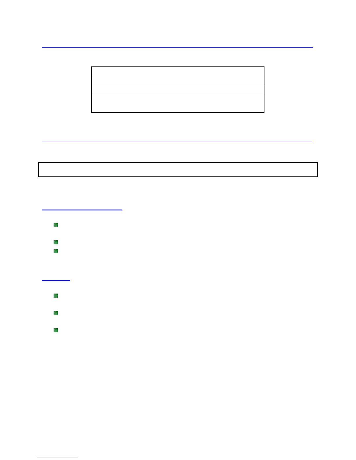
VACUGUARD W/2A CABLE, BAG
2-3001-103
VACUGUARD W/ 2AMINI CABLE, BAG
2-3001-104
VACUGUARD W/2A & DV4/6 CABLE,
2-3001-105
VACUGUARD W/2A &DV4/6 CABLE,
2-3001-106
w/ BAG & NICAD B ATTERY & CHARGER
SUNSTAR传感与控制 http://www.sensor-ic.com/ TEL:0755-83376549 FAX:0755-83376182 E-MAIL:[email protected]
SUNSTAR传感与控制 http://www.sensor-ic.com/ TEL:0755-83376549 FAX:0755-83376182 E-MAIL:[email protected]
CHAPTER 9 TELEVAC
Unpacking and inspection
Inventory the Contents
Compare the list of items from y our original purchase documents against the items
list ed on our shipping documents.
Compare these against the actual contents of the shipping container.
Report any differences to TELEVAC.
Damage
In the unlikely event that the shipping container was damaged in transit, carefully
inspect the contents for damage.
If the MV2A Instrument or any of its accessories were damaged in transit, contact
the freight carrier and tell t hem you wish to make a damage claim.
Contact TELEVAC for further instructi ons on replacement of damaged materials.
Should any of the above problems be encountered, contact the factory immediately.
Any unauthorized repairs will void the warranty.
Page 14

SUNSTAR传感与控制 http://www.sensor-ic.com/ TEL:0755-83376549 FAX:0755-83376182 E-MAIL:[email protected]
SUNSTAR传感与控制 http://www.sensor-ic.com/ TEL:0755-83376549 FAX:0755-83376182 E-MAIL:[email protected]
CHAPTER 10 TELEVAC
Warranty Information
The Fredericks Company warrants all instruments and components of its
manufacture to be free of defects in material s and workmanship.
Our obligation under this warranty is limited to servicing or adjusting any
instrument returned to us and replacing any part, except those specifically exempt
from this guarantee, which shall within one year after delivery to the original
purchaser be returned to us with transportation charges prepaid, and which our
examination should disclose to our satisfaction to have been defective. Those
portions specifically exempt from this guarantee are gauge tubes, batteries as well
as meters, which have been dissembled or physically damaged.
The Fredericks Company does not assume any other obligation than that stated in
this warranty nor does it authorize any person to assume for them any liability in
connection with the sale, service or use of the Fredericks Company’s instruments.
 Loading...