

Page 1

Televac Application Note 3018
MX200 EthernetIP Vacuum Controller
Setup and Troubleshooting Guide for EthernetIP Option 2
Contents
1 Description....................................................................................................................................................... 1
2 Windows™ 7 Operating Systems Configuration ................................................................................................ 2
3 Windows™ 10 Operating Systems Configuration .............................................................................................. 7
4 Contact Us ..................................................................................................................................................... 12
1 Description
This document explains the process for the setup, configuration, and troubleshooting of a Televac EthernetIP device.
In order to communicate with the unit, the EthernetIP device’s IP address will need to be configured to the same
network as the PLC. The following steps describe how to establish the initial connection, and what steps to follow
should any issues arise. The second setup option assumes no internet connectivity and explains how to reconfigure
the IP address of the local computer to match the module, which can then be connected to in order to adjust the
settings to the appropriate configuration. If an internet connection is available, refer to the Setup and
Troubleshooting Guide for Televac EthernetIP Option 1 (televac_an3017).
Please see the EthernetIP for MX200 User Manual for a full description on Class 1 and Class 3 connections, and a
complete ADI table including data instance, name, array length, access, and description. Please see Application
Note 3016 for downloading an Electronic Data Sheet (EDS) file to a PLC.
© 2017 The Fredericks Company | www.frederickscompany.com | sales@frederickscompany.com | +1 215 947 2500 televac_an3018 rev - Page 1 of 12
Page 2
2 Windows™ 7 Operating Systems Configuration
2.1 Configuring the IP Address
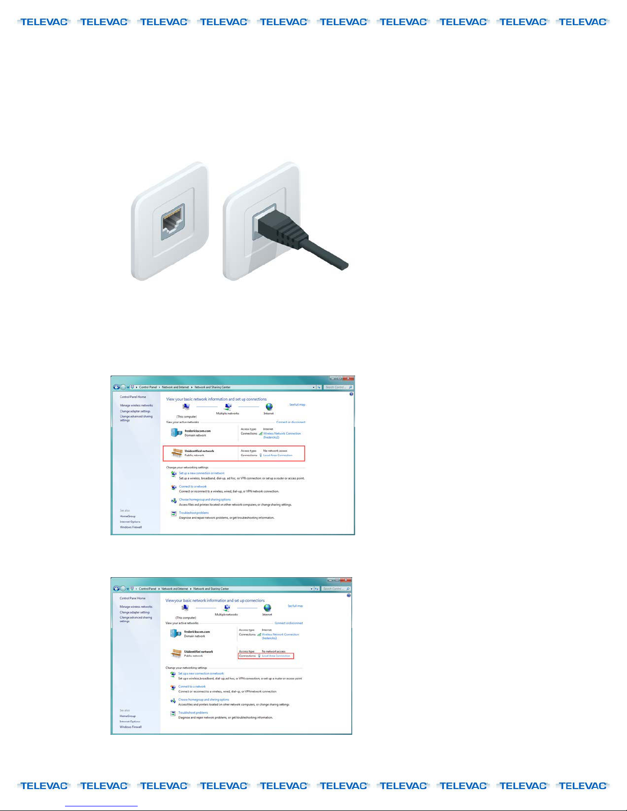
2.1.1 Connect the MX200 EthernetIP port on the back of the unit to your computer.
2.1.2 Open the Network and Sharing Center in the Control Panel and verify that an Ethernet connection is being
made. If there is no connection, check the cable and reinsert the Ethernet cable into the adapter on the
computer.
2.1.3 Select the Ethernet Local Area Connection.
© 2017 The Fredericks Company | www.frederickscompany.com | sales@frederickscompany.com | +1 215 947 2500 televac_an3018 rev - Page 2 of 12
Page 3
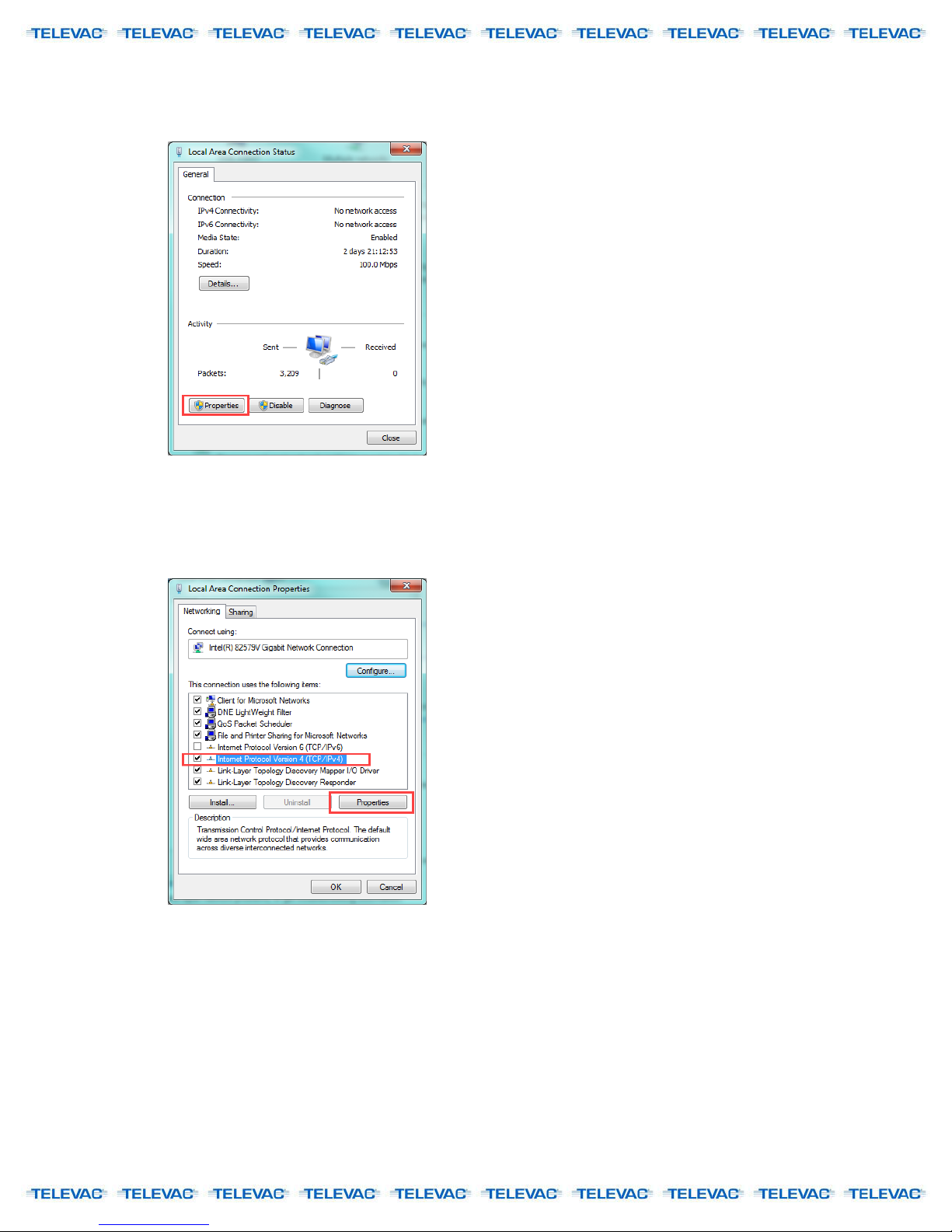
2.1.4 In the Local Area Connection Status panel, select Properties.
2.1.5 In the Local Area Connection Properties panel, select Internet Protocol Version 4 (TCP/IPv4) and select
Properties.
© 2017 The Fredericks Company | www.frederickscompany.com | sales@frederickscompany.com | +1 215 947 2500 televac_an3018 rev - Page 3 of 12
Page 4

2.1.6 In the Internet Protocol Version 4 Properties panel, mark down the current settings to revert back to later.
The local machine will need to be configured to the module to adjust the settings, but will need to be
brought back onto the local network in order to communicate properly when finished. In this example,
the local machine has an IPv4 address of 149.174.211.52 with a subnet mask of 255.255.0.0 and a default
gateway of 149.174.211.2.
2.1.7 Adjust the settings of the computer to an IP address of 192.168.0.9, a subnet mask of 255.255.255.0, and
a default gateway of 192.168.0.8, and select OK.
© 2017 The Fredericks Company | www.frederickscompany.com | sales@frederickscompany.com | +1 215 947 2500 televac_an3018 rev - Page 4 of 12
Page 5

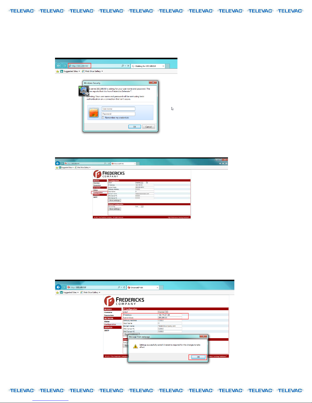
2.1.8 The computer and unit should now be on the same local network. Open a browser, and enter the IP
address of the unit (192.168.0.8) into the search bar. When prompted, enter the username and password
(default Admin:admin).
2.1.9 The web page hosted by the module should appear. Select the Configuration tab on the left.
2.1.10 Change the IP address and subnet mask to the desired configuration (see step 2.1.6 for the network
configuration). In this example, step 2.1.6 showed that the network needed is 149.174.211.X with a
subnet mask of 255.255.0.0. The unit in this example will be configured to an IP address of
149.174.211.99, which has been verified to not conflict with any other IP address on the network. Select
Save Settings to finish the configuration, and cycle the power to the unit for the changes to take effect.
© 2017 The Fredericks Company | www.frederickscompany.com | sales@frederickscompany.com | +1 215 947 2500 televac_an3018 rev - Page 5 of 12
Page 6

2.1.11 The unit is now configured to the network. Follow steps 2.1.2 to 2.1.7 to change the local computer back
to the original settings (original settings are the noted settings in step 2.1.6).
2.2 Verifying the Setup
2.2.1 After the IP address and subnet mask are configured, network connectivity can be verified through the
PLC or through the web functionality. To verify through the web functionality, type the IP address into
address bar in the browser and enter the username and password (default Admin:admin).
2.2.2 If the unit is connected to the network properly, the web page should be displayed. From here, data
parameters can be viewed and changed along with current EthernetIP network settings.
2.2.3 The unit should now be ready to use with a PLC. Please refer to Televac Application Note 3016 for
downloading the Electronic Data Sheet (EDS) and creating a connection.
© 2017 The Fredericks Company | www.frederickscompany.com | sales@frederickscompany.com | +1 215 947 2500 televac_an3018 rev - Page 6 of 12
Page 7

3 Windows™ 10 Operating Systems Configuration
3.1 Configuring the IP Address
3.1.1 Connect the MX200 EthernetIP port on the back of the unit to your computer.
3.1.2 Open the Network and Sharing Center in the Control Panel and verify that an Ethernet connection is being
made. If there is no connection, check the cable and reinsert the Ethernet cable into the adapter on the
computer.
3.1.3 Select the Ethernet Connection.
© 2017 The Fredericks Company | www.frederickscompany.com | sales@frederickscompany.com | +1 215 947 2500 televac_an3018 rev - Page 7 of 12
Page 8
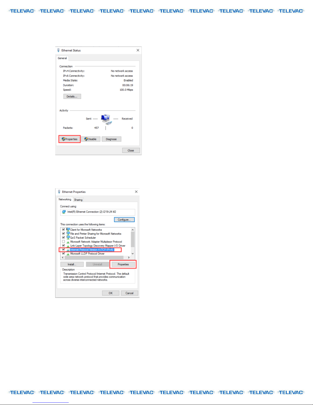
3.1.4 In the Ethernet Status panel, select Properties.
3.1.5 In the Ethernet Properties panel, select Internet Protocol Version 4 (TCP/IPv4) and select Properties.
© 2017 The Fredericks Company | www.frederickscompany.com | sales@frederickscompany.com | +1 215 947 2500 televac_an3018 rev - Page 8 of 12
Page 9

3.1.6 In the Internet Protocol Version 4 Properties panel, mark down the current settings to revert back to later.
The local machine will need to be configured to the module to adjust the settings, but will need to be
brought back onto the local network in order to communicate properly when finished. In this example,
the local machine has an IPv4 address of 149.174.211.116 with a subnet mask of 255.255.0.0 and a
default gateway of 149.174.211.2.
3.1.7 Adjust the settings of the computer to an IP address of 192.168.0.9, a subnet mask of 255.255.255.0, and
a default gateway of 192.168.0.8, and select OK.
© 2017 The Fredericks Company | www.frederickscompany.com | sales@frederickscompany.com | +1 215 947 2500 televac_an3018 rev - Page 9 of 12
Page 10
3.1.8 The computer and unit should now be on the same local network. Open a browser, and enter the IP
address of the unit (192.168.0.8) into the search bar. When prompted, enter the username and password
(default Admin:admin).
3.1.9 The web page hosted by the module should appear. Select the Configuration tab on the left.
3.1.10 Change the IP address and subnet mask to the desired configuration (see step 3.1.6 for the network
configuration). In this example, step 3.1.6 showed that the network needed is 149.174.211.X with a
subnet mask of 255.255.0.0. The unit in this example will be configured to an IP address of
149.174.211.99, which has been verified to not conflict with any other IP address on the network. Select
Save Settings to finish the configuration, and cycle the power to the unit for the changes to take effect.
© 2017 The Fredericks Company | www.frederickscompany.com | sales@frederickscompany.com | +1 215 947 2500 televac_an3018 rev - Page 10 of 12
Page 11

3.1.11 The unit is now configured to the network. Follow steps 3.1.2 to 3.1.7 to change the local computer back
to the original settings (original settings are the noted settings in step 3.1.6).
3.2 Verifying the Setup
3.2.1 After the IP address and subnet mask are configured, network connectivity can be verified through the
PLC or through the web functionality. To verify through the web functionality, type the IP address into
address bar in the browser and enter the username and password (default Admin:admin).
3.2.2 If the unit is connected to the network properly, the web page should be displayed. From here, data
parameters can be viewed and changed along with current EthernetIP network settings.
3.2.3 The unit should now be ready to use with a PLC. Please refer to Televac Application Note 3016 for
downloading the Electronic Data Sheet (EDS) and creating a connection.
© 2017 The Fredericks Company | www.frederickscompany.com | sales@frederickscompany.com | +1 215 947 2500 televac_an3018 rev - Page 11 of 12
Page 12

4 Contact Us
Please feel free to contact us with any questions:
The Fredericks Company - Televac
2400 Philmont Avenue
Huntingdon Valley, PA 19006, USA
Web: www.frederickscompany.com
Email: sales@frederickscompany.com
Phone: +1 215 947 2500
© 2017 The Fredericks Company | www.frederickscompany.com | sales@frederickscompany.com | +1 215 947 2500 televac_an3018 rev - Page 12 of 12
 Loading...