

Page 1
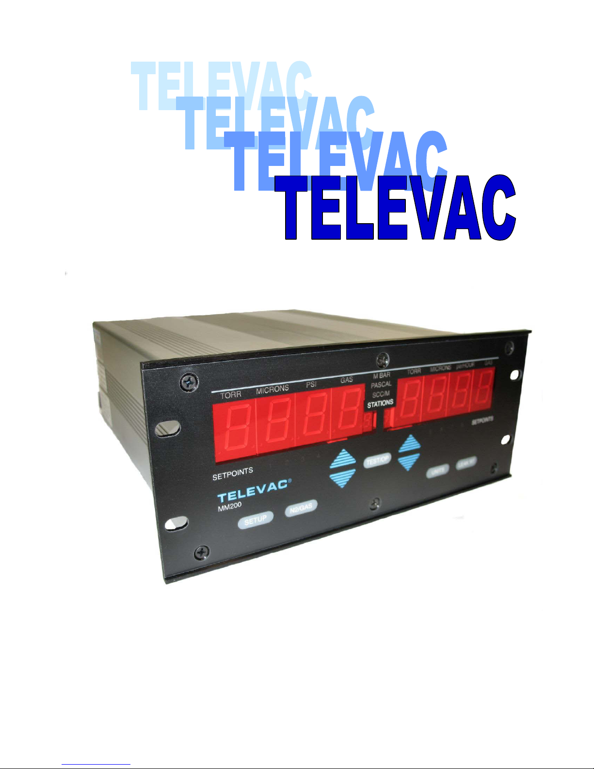
MM200
TELEVAC
A DIVISION OF THE FREDERICKS COMPANY
2400 PHILMONT AVE.
HUNTINGDONVALLEY, PA 19006
Page 2
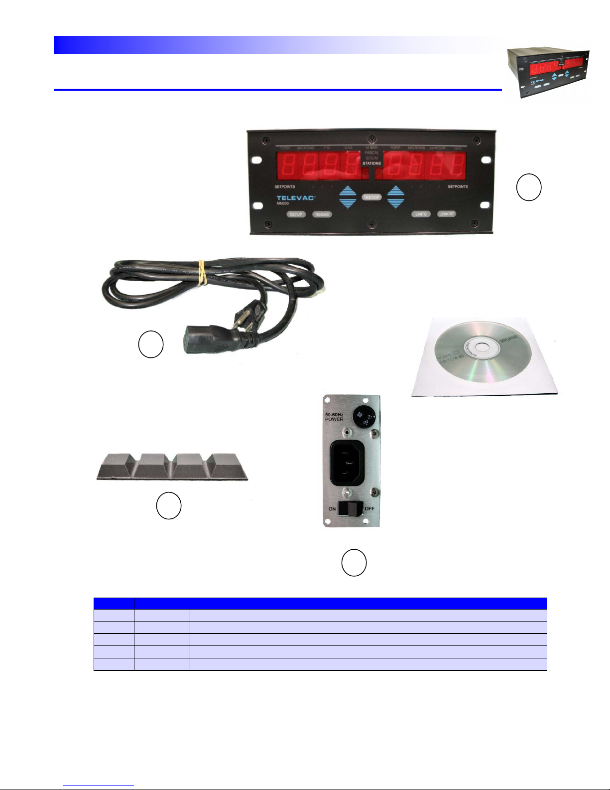
TELEVAC
PARTS
#
QTY
ITEM DESCRIPTION
1
1
MM200
2
1
Instruction Manual
3
1
AC Power Cable
4
1
Power supply module
5
1 SET
Rubber Feet
1 3 4
5
INSTRUMENT MANUAL
VACUUM GAUGE MODEL MM200
160Phone:(215) 947-2500 fax:(215) 947-7464 e-mail:sales@televac.com web site:www.televac.com
MM-200_im REV M
Page 1 of 160
Page 3

TELEVAC
TABLE OF CONTENTS
INSTRUMENT MANUAL
VACUUM GAUGE MODEL MM200
SECTION TITLE PAGE
TABLE OF CONTENTS 1
100 INTRODUCTION 10
101 DESCRIPTION 10
102 STANDARD FEATURES 11
Measurement Expansion 11
Sensor interface Modules 11
Computer Interface Modules 11
Non-volatile Memory 11
Display 11
Keyboard 11
CPU Configuration 11
103 SETPOINT RELAYS 11
104 VACUUM GAUGE TUBES 11
Diaphragm 12
Thermocouple 12
Convection 12
Cold Cathode 12
Hot Cathode 12
Capacitance Diaphragm Gauge 13
200 INITIAL CHECKOUT 14
201 UNPACKING AND INSPECTION PROCEDURES 14
202 INVENTORY 14
203 INTIAL CHECK PROCEDURES 14
Correct Operating Voltage 14
Initial Displays 15
160Phone:(215) 947-2500 fax:(215) 947-7464 e-mail:sales@televac.com web site:www.televac.com
MM-200_im REV M
Page 2 of 160
Page 4

TELEVAC
INSTRUMENT MANUAL
VACUUM GAUGE MODEL MM200
SECTION TITLE PAGE
300 INSTALLATION 18
301 MODULE CONFIGURATION 18
302 LINE VOLTAGE SELECTION 23
303 GAUGE CONTROLLER INSTALLATION 23
Freestanding 23
Rack Mounted 23
304 GAUGE SENSOR INSTALLATION WARNINGS 24
305 VACUUM CONNECTION FITTINGS 25
NPT Pipe Thread Connections 25
0-ring Compression Fittings 25
Conflat Flange Fittings 25
KF Flange Connections 26
Cajon Fittings 26
306 GAUGE SENSOR INSTALLATION 26
307 REMOVAL AND INSTALLATION OF MODULES 27
308 DESCRIPTION OF MODULES 28
Power Supply Module 28
Setpoint Relay Module 29
Communications Module 29
Thermocouple Module 30
Convection Module 31
Diaphragm Module 31
Cold Cathode Module 32
3D Hot Cathode Resident Module (I² R Degas) 32
3E Hot Cathode Resident Module (EB Degas) 34
3F Hot Cathode Mini BA Module (software ver. 2.31 or higher) 35
Capacitance Diaphragm Modules 38
160Phone:(215) 947-2500 fax:(215) 947-7464 e-mail:sales@televac.com web site:www.televac.com
MM-200_im REV M
Page 3 of 160
Page 5

TELEVAC
INSTRUMENT MANUAL
VACUUM GAUGE MODEL MM200
SECTION TITLE PAGE
400 OPERATION 40
401 DISPLAY DESCRIPTION DEFINITIONS 40
Station Number 40
Data Display 41
Units 41
Gas Type 41
Leak Rate Indicator 41
Setpoint Relay Status Indicator 41
402 ERROR INDICATIONS 41
403 KEYPAD DESCRIPTION 42
PUSHBUTTON Functions 43
TEST/OP Pushbutton 43
SETUP Pushbutton 43
N2/GAS Pushbutton 43
UP/DOWN Arrows 43
UNITS Pushbutton 43
LEAK RT Pushbutton 43
404 RELAY SETPOINTS 43
Range of Use 44
Changing Sensor Assignment 44
405 ANALOG 0-10V OUTPUTS 45
0-10V Outputs 46
0-10V Output Options 49
406 INITIAL OPERATION SETUP SEQUENCE 50
Pressure Readings 50
Relay Setup 50
Gas 51
Measurement Units 51
Leak rate 51
407 3F HOT CATHODE MODULE (Mini BA) (software ver. 2.31 or higher) 52
Sensitivity 52
Degas 52
Filament 52
160Phone:(215) 947-2500 fax:(215) 947-7464 e-mail:sales@televac.com web site:www.televac.com
MM-200_im REV M
Page 4 of 160
Page 6

TELEVAC
INSTRUMENT MANUAL
VACUUM GAUGE MODEL MM200
SECTION TITLE PAGE
500 SETUP 53
501 INTIALIZATION 53
Initial Displays 53
502 USE OF PUSHBUTTONS 54
TEST/OP Pushbutton 54
Return to Normal Operation 54
Self-Diagnostic Test 54
UP/DOWN Arrows 56
SETUP Pushbutton 56
Cold Cathode Setup 56
3D & 3E Hot Cathode Setup 59
Degass Timer 62
Relay Setpoints 62
SP#1 – Station Assignment 62
SP#1 – Setpoint Selection 62
UNITS Pushbutton 63
N2/GAS Pushbutton 64
LEAK RT Pushbutton 64
HANDLING UNITS 64
For versions 2.31 or higher. Refer to Section 6.2, page 602
503 3F HOT CATHODE MODULE (Mini-BA) 65
F (AUTO or SELF or BOTH) 65
FIL (ON or OFF or RDY) 65
DGAS (0FF or ON) 65
DGAS (# time) 65
FIL NBR (1 or 2) 65
SENS (# sensitivity) 65
160Phone:(215) 947-2500 fax:(215) 947-7464 e-mail:sales@televac.com web site:www.televac.com
MM-200_im REV M
Page 5 of 160
Page 7

TELEVAC
INSTRUMENT MANUAL
VACUUM GAUGE MODEL MM200
SECTION TITLE PAGE
600 COMMUNICATIONS 66
601 RS232 INTERFACING WITH COMPUTER USING MICROSOFT HYPER 66
TERMINAL
602 RS232 / RS485 PROTOCOL FOR SOFTWARE VERSIONS 2.31 OR HIGHER 67
RS232 or RS485 67
STD or ALT 67
UNIT #xx 67
PREF #xx 67
RS485 Prefix and Addresses Table – For Software Ver. 2.31 or Higher 68
New Commands For MM200 - For Software Ver. 2.31 or Higher 69
Commands That Have Been Updated For 3F Modules 69
Commands For The 3F Hot Cathode MINI-BA Module 70
603 COMMUNICATIONS – FOR SOFTWARE VER. 1.35 – 2.31 70
604 RS232/RS485 COMMANDS 70
RS232/RS485 70
Communications 75
Configuration 77 Data
Output 79
Display 81
Gas 82
Hot Cathode 83
Leak Rate 84
Outputs 85
Set Point Setting Values 88
Convection Gauge 4A atmosphere Adjustment 92
Zeroing Thermocouple, Convection, and Diaphragm Gauges 92
RS232/RS485 Command Summary 95
RS485 Host Command Set 99
RS232 Commands Used To Implement RS485 101
Alternate address Scheme for RS485 102
Special Commands 102
RS232 Hardware 103
RS485 Hardware 103
605 COMMUNICATIONS – FOR SOFTWARE VER. 1.21 – 1.34 104
RS232 Protocol 104
606 COMMAND SUMMARY – FOR SOFTWARE VER. 1.19 – 1.20 105
Hardware 108
Commands 109
“B” Mode Commands 109
Cold Cathode 110
160Phone:(215) 947-2500 fax:(215) 947-7464 e-mail:sales@televac.com web site:www.televac.com
MM-200_im REV M
Page 6 of 160
Page 8

TELEVAC
INSTRUMENT MANUAL
VACUUM GAUGE MODEL MM200
SECTION TITLE PAGE
606 COMMAND SUMMARY – FOR SOFTWARE VER. 1.19 – 1.20
Communications 111
127 Data Output 113
Hot Cathode 115
Leak Rate 116
Output Formats 117
Set Points 117
Set Point Setting Values 118
607 COMMUNICATIONS – FOR SOFTWARE VER. 1.0 – 1.19 119
RS232 Protocol 119
RS232 Hardware 127
Special Commands 127
160Phone:(215) 947-2500 fax:(215) 947-7464 e-mail:sales@televac.com web site:www.televac.com
MM-200_im REV M
Page 7 of 160
Page 9

TELEVAC
INSTRUMENT MANUAL
VACUUM GAUGE MODEL MM200
SECTION TITLE PAGE
700 CALIBRATION 128
701 ELECTRICAL "VERIFICATION" 128
Equipment Required 128
Procedure 129
702 VACUUM CALIBRATION 129
Equipment Required 130
Procedure 131
703 CALIBRATION FOR ALTERNATE GASSES 133
800 SPECIFICATIONS 134.
801 CONTROLLER SPECIFICATIONS 134
802 CONTROLLER DIMENSIONS 134
803 SENSORS 135
804 ORDERING INFORMATION 135
900 TROUBLESHOOTING 137
901 PRELIMINARY TROUBLESHOOTING 137
902 SETUP OF MODULE BOARDS 138
Setpoint relay module 138
Digital interface module 140
Thermocouple module 141
Convection module 143
Cold Cathode module 145
Diaphragm modules 149
Capacitance Diaphragm module 151
3D Hot Cathode module 153
3E Hot Cathode module 154
903 DRAWINGS AND SCHEMATICS 155
904 CLEANING COLD CATHODE GAUGE TUBES 156
905 SUPPRESSOR INSTALLATION FOR NOISY ENVIRONMENTS 157
160Phone:(215) 947-2500 fax:(215) 947-7464 e-mail:sales@televac.com web site:www.televac.com
MM-200_im REV M
Page 8 of 160
Page 10

TELEVAC
INSTRUMENT MANUAL
VACUUM GAUGE MODEL MM200
SECTION TITLE PAGE
1000 MISCELLANEOUS 158
CALIBRATION MODE 158
DIAPHRAGM GAUGES 158
INSTALLATION OF EPROMS 159
160Phone:(215) 947-2500 fax:(215) 947-7464 e-mail:sales@televac.com web site:www.televac.com
MM-200_im REV M
Page 9 of 160
Page 11
TELEVAC
INSTRUMENT MANUAL
VACUUM GAUGE MODEL MM200
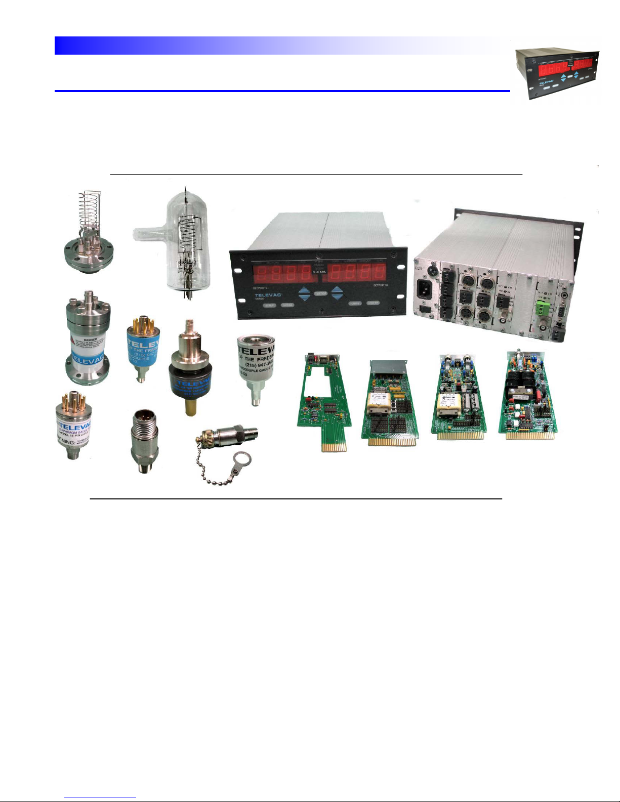
100 INTRODUCTION
This manual provides information pertaining to the installation, operation, and maintenance of the Televac MM 200
vacuum gauge. Various sensor modules, their options, and associated sensors are covered in this manual.
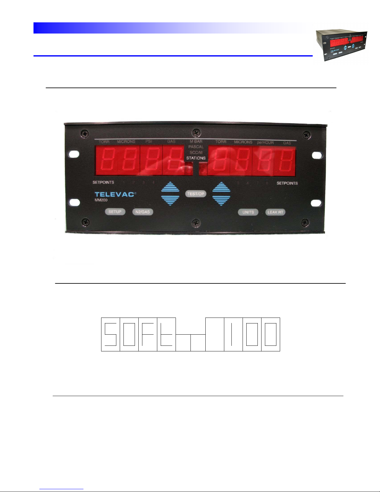
Fig. 1.1 - TELEVAC Modular Gauge
101 DESCRIPTION
The TELEVAC MM200 programmable vacuum gauge controller consists of a basic electronic unit and modular
sensor signal processing interface boards. These components utilize the latest in digital and analog technology
and provide a versatile, easy to use means for measuring pressure (vacuum). With the appropriate system and
sensors, pressures ranging from 10
vacuum chamber leak-up rate can be measured. A large selection of sensors and mounting configurations, as well
as hardware control interfaces, are available for user convenience.
There is one basic electronics unit, which accepts modules for all gauge types as well as relay modules and digital
interface modules. Several sensors are presently available. These are described in Section 104. Other sensor
modules will be available in the future. User-installed modules permit expansion. The controller provides a choice
of display data formats, display
-11
Torr through 7.5 x 10
+ 3
(10 Bar) are accurately monitored. Additionally,
160Phone:(215) 947-2500 fax:(215) 947-7464 e-mail:sales@televac.com web site:www.televac.com
MM-200_im REV M
Page 10 of 160
Page 12

TELEVAC
INSTRUMENT MANUAL
VACUUM GAUGE MODEL MM200
102 STANDARD FEATURES
MEASUREMENT EXPANSION - The electronics unit can support additional measurement modules. These
additional modules can be any mix of the above listed sensors.
SENSOR INTERFACE MODULES - Each gauge has several available sensor interface modules (See Section 300).
These modules contain the signal conditioning and measurement circuitry required to operate the sensor properly.
They also provide the user with a scalable analog output of pressure.
COMPUTER INTERFACE MODULES - The computer interface provides a means for electronic communication
with the gauge controller. An RS232 and an RS485 serial data link is provided. The data format is discussed in
Section 600.
NON-VOLATILE MEMORY - The instrument contains non-volatile memory (EEPROM) that saves all programmable
SETUP parameters when the instrument power is off.
DISPLAY - The display system for all gauges has two large multiplexed light emitting diode (LED) displays. Each
display can show a maximum of four (4) digits of data including an exponent. The display also has smaller displays
which indicate selected station number, selected measurement units, alternate gas type, and setpoint relay status.
KEYPAD - The keypad is a tactile feel, non-membrane unit that provides keys for programming and control
operations. The number of keys has been optimized for simple operation.
CPU CONFIGURATION - The central processing unit (CPU) provides the operator choices for the display format,
measurement units, communications format and baud rates as well as the ability to lock out keyboard parameter
changes.
103 SETPOINT RELAYS
The Process Control Relay or Setpoint Relay Module provides four (4) relays per module (eight maximum. These
relays are assignable to any installed station.
104 VACUUM GAUGE TUBES
This instrument supports several types of vacuum gauge tubes (sensors). Combinations of sensors can be used to
cover a wide range of absolute pressures. These
sensors can also be used to make measurements in several locations.
160Phone:(215) 947-2500 fax:(215) 947-7464 e-mail:sales@televac.com web site:www.televac.com
MM-200_im REV M
Page 11 of 160
Page 13

TELEVAC
INSTRUMENT MANUAL
VACUUM GAUGE MODEL MM200
104 VACUUM GAUGE TUBES (cont.)
DIAPHRAGM GAUGE - Measures absolute pressure by detecting very small deflections of a metal diaphragm via
a strain gauge. It is not sensitive to gas type. These sensors are temperature compensated, but do respond to
rapid changes of temperature. Temperature changes cause zero shifts. Users should note that occasional
adjustments of the zero point are normal for sustaining accuracy with this type of sensor, and provision for making
this adjustment should be included in the installation. Fine adjustment of the zero and atmospheric point is
accomplished at the rear panel on the diaphragm module. Sensor range: 1E: 1 to 800 Torr; 1F: 1000 to 9999
mbar.
THERMOCOUPLE GAUGE - Measures absolute pressures by determining the heat loss from a fine wire filament.
The response of the sensor depends on the gas type. These sensors are compensated for room temperature
variation and are calibrated for vertical operation but operate with little error in any orientation. "Zero" calibration
potentiometers are provided for occasional adjustment as required. Sensor range: 10-3 to 20 Torr.
CONVECTION GAUGE - Measures absolute pressures by determining the heat loss from a fine wire filament. The
response of the sensor depends on the gas type. These sensors are compensated for room temperature variation
and are calibrated for operation in the VERTICAL POSITION ONLY. ZERO and ATM (atmospheric pressure)
calibration potentiometers are provided for occasional adjustment as required. Sensor range: 10-3 to 10+3 Torr.
COLD CATHODE GAUGE - A high vacuum sensor that measures pressure by ionizing the residual gases in a
magnetron discharge. The body of the gauge serves as the cathode, and is at ground potential. The anode
operates at voltages up to 3000 volts. A permanent magnet traps electrons in the gauge to sustain the discharge at
very low pressure. This type of gauge may be less precise in its reading than hot cathode gauges and, like the hot
cathode gauge, is also sensitive to gas type. However, it is relatively rugged and has no filament to burn out, so
that it is often used in applications where hot cathode gauges are not reliable. Cold cathode tubes might experience
ignition time delay when trying to turn them on at high vacuum. The 7FCS quick start gauge has a thermo emission
igniter inside so every time when power applies to MM200 the filament goes on for 5 second to start ionization
chain reaction.There are various designs to cover different pressure (vacuum) ranges. Refer to Table 4.1. Sensor
range: 10
-11
to 10-2 Torr.
HOT CATHODE GAUGE - Hot cathode gauges typically have the Bayard-Alpert geometry and are used for high
vacuum measurements. Both glass enclosed and nude sensors are available. These sensors measure absolute
pressures by sensing the ion current generated by the interaction of a beam of electrons from a hot filament with
gas molecules in the vacuum system. This kind of gauge is sensitive to gas types. Filaments can be tungsten or
Thoria-Coated Iridium. The Iridium filaments don't burn out as readily if accidentally exposed to air when hot, but
can be attacked by chlorides and fluorides, which decompose the coating. Tungsten filaments also run noticeably
hotter. It is normal for such gauges to have a residual current (the x-ray limit), which may introduce significant
errors below 10
outgassing when the hot filament is turned on. Degassing is often used to accelerate this process prior to making
measurements at very low pressures. Sensor range: 10
-10
Torr depending on construction. It is also normal for sensors to generate significant amounts of
-11
to 10-2 Torr.
The pressure range for various sensors is shown in Table 4.1.
160Phone:(215) 947-2500 fax:(215) 947-7464 e-mail:sales@televac.com web site:www.televac.com
MM-200_im REV M
Page 12 of 160
Page 14

TELEVAC
NOTE:
Capacitance Diaphragm Gauge Tubes with a range of greater than 1 Torr will not control the Cold
Cathode automatic turn on!
INSTRUMENT MANUAL
VACUUM GAUGE MODEL MM200
104 VACUUM GAUGE TUBES (cont.)
CAPACITANCE DIAPHRAGM GAUGE - Measures absolute pressure by detecting very small deflections of a
metal diaphragm via a change in capacitance between the diaphragm and one or more electrodes. It is not
sensitive to gas type. These sensors are temperature compensated, but do respond to rapid changes of
temperature. Temperature changes cause zero shifts. In some cases the gauges are heated for stability and to
prevent condensation of process gasses. Users should note that occasional adjustments of the zero point are
normal for sustaining accuracy with this type of sensor, and provision for making this adjustment should be included
in the installation. Fine adjustment of the zero and atmospheric point is accomplished at the rear panel on the
diaphragm module. Sensor ranges (full scale):
5A = 1000 Torr; 5B = 100 Torr; 5C = 10 Torr
5D = 1 Torr; 5E = 0.1 Torr; 5F = special
160Phone:(215) 947-2500 fax:(215) 947-7464 e-mail:sales@televac.com web site:www.televac.com
MM-200_im REV M
Page 13 of 160
Page 15

TELEVAC
INSTRUMENT MANUAL
VACUUM GAUGE MODEL MM200
200 INITIAL CHECKOUT
201 UNPACKING AND INSPECTION PROCEDURES
1. Remove the Vacuum Gauge Controller from its shipping container
2. Carefully examine the unit for damage that may have occurred during shipping. This is especially important
if you notice signs of obvious rough handling on the outside of the cartons. REPORT ANY DAMAGE TO
THE CARRIER AND TO TELEVAC IMMEDIATELY.
3. DO NOT discard any packing materials until you have taken inventory and completed the check
procedures. You may wish retain the packing material for later use.
4. If the instrument must be returned to TELEVAC be sure to contact the service department (215-947-2500)
for a Return Material Authorization (RMA) number. Items will not be accepted without an assigned RMA.
They must be packaged, insured and shipped with transportation charges prepaid to:
TELEVAC - Division of
The Fredericks Company
2400 Philmont Avenue
Huntingdon Valley, PA 19006
202 INVENTORY
Compare the contents of the shipping containers with the invoice to be sure you received all necessary equipment.
203 INITIAL CHECK PROCEDURES
For the Initial Check Procedure you need only the control unit and the power cord. Do not connect any sensors,
cables or other devices to the unit for this check.
CORRECT OPERATING VOLTAGE - Before connecting the power cord, check the line voltage selector, which is
part of the power supply board at the rear of the unit. For 100-120V application the arrow should point to the
embossed "110" on the switch as shown in Fig. 2.1. To change to 220-240V, use a small screwdriver to turn the
switch from its position to align the arrow with the embossed "220" on the switch. (220V not permitted for
Capacitance Diaphragm Gauges. Make sure that the power switch is OFF and then plug the power cord into the
unit's socket and an appropriate outlet.
It is recommended that a surge protector circuit is used or make sure that your power line is safe from power surge.
The noise (power surge) through the power line may alter the contents of a non-volatile memory (known as data
memory) in EEPROM and cause the controller to operate erratically.
160Phone:(215) 947-2500 fax:(215) 947-7464 e-mail:sales@televac.com web site:www.televac.com
MM-200_im REV M
Page 14 of 160
Page 16
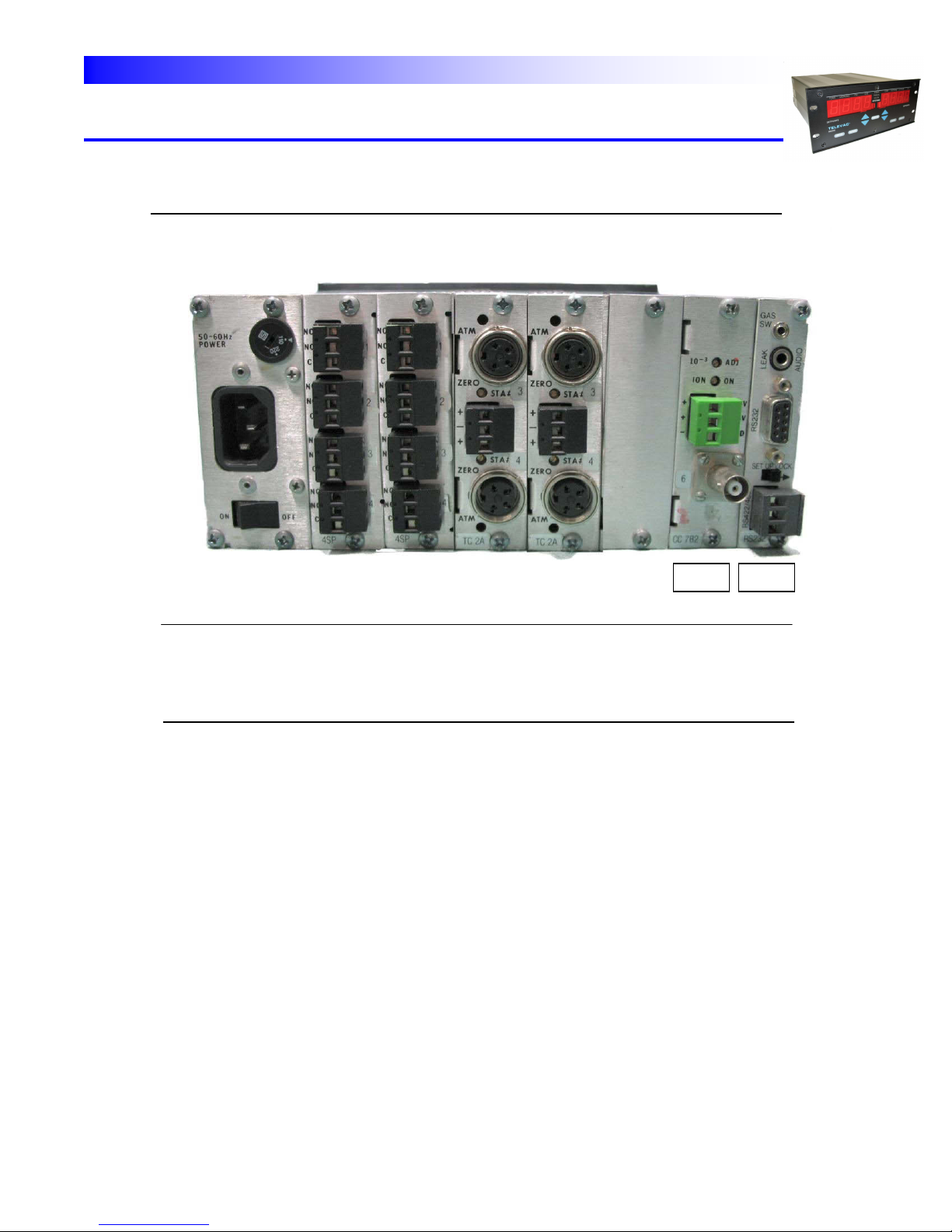
TELEVAC
CC 7E
RS485
POSITION #0 #1 #2 #3 #4 #5 #6 #7
INSTRUMENT MANUAL
VACUUM GAUGE MODEL MM200
WARNING: Voltages may exist on rear panel connectors.
DO NOT touch the exposed connectors when power is connected to the
instrument.
Note that the rear panel configuration shown in Fig. 2.1 is just one of the many possible combinations of gauges
and relay modules. This configuration has the following characteristics:
MM200 - Microprocessor with power supply,
4 relays, 5 stations and RS232
SLOT 0 - Power supply
SLOT 1 - S1- Setpoint relay module
SLOT 2 - S1- Setpoint relay module
SLOT 3 - T1- Dual thermocouple module (2 stations)
SLOT 4 - C1- Dual convection module (2 stations)
SLOT 5 - B1- Blank panel
SLOT 6 - C1- Cold cathode module (1 station)
SLOT 7 - R1- RS232 /RS485 module
INITIAL DISPLAYS - The front panel (shown in Fig. 2.2) is used to observe the displays and to execute the initial
self-test of the unit. Remove the protective plastic covering over the displays. Turn the power on by pressing the
rear panel power switch to ON. The initial display shows the word "SOFt" followed by a number indicating which
software version is present (See Fig. 2.3).
160Phone:(215) 947-2500 fax:(215) 947-7464 e-mail:sales@televac.com web site:www.televac.com
MM-200_im REV M
Page 15 of 160
Page 17
TELEVAC
Fig. 2.2 – Front Panel
.
Fig. 2.3 – Software Version
INSTRUMENT MANUAL
VACUUM GAUGE MODEL MM200
160Phone:(215) 947-2500 fax:(215) 947-7464 e-mail:sales@televac.com web site:www.televac.com
MM-200_im REV M
Page 16 of 160
Page 18

TELEVAC
Fig. 2.4 - Typical Initial Display
INSTRUMENT MANUAL
VACUUM GAUGE MODEL MM200
This message is followed by an error code, if any errors are present. (see Section 900). If no errors are present,
the initial display for the installed sensor modules appears.
In the initial right-hand display, the default mode is to display the lowest number station installed (except ionization
type gauge if there are other than ionization gauges installed). Since no sensor and/or cable is plugged in, the
right-hand display reads "CAbL" and the adjacent small number reads the corresponding station number (typically
#1). The left hand display shows the lowest number ionization (cold cathode or hot cathode) station installed
(station #7 in the example shown in Fig. 2.4). Since the high voltage power is off, the display reads "OFF". (See
Fig. 2.4). If no ionization gauge is installed, the left-hand display shows the second lowest station installed.
Fig. 2.4 shows the correct initial display for this configuration. If a display does not appear, check the power outlet
and the main fuse on the rear of the unit.
If further checkout is desired, refer to Section 502.
Assuming that the initial display check is successful, the instrument if ready for installation. Otherwise contact your
TELEVAC Service Department (See front cover).
160Phone:(215) 947-2500 fax:(215) 947-7464 e-mail:sales@televac.com web site:www.televac.com
MM-200_im REV M
Page 17 of 160
Page 19

TELEVAC
INSTRUMENT MANUAL
VACUUM GAUGE MODEL MM200
300 INSTALLATION
301 MODULE CONFIGURATION
A controller is normally ordered with various optional sensor interface modules and they are factory installed before
shipment. Before installation, verify that the selection of modules will accomplish the desired results in your
application. If additional modules are required or you have any questions about using this gauge in your
application, please call Televac at 215-947-2500. If you wish to add modules, refer to Section 307 AND 308.
One possible configuration for this gauge was shown in Section 203. The allowable configurations are restricted by
the number of cold cathode and/or hot cathode ionization stations installed.
The MM200 has six slots, which can be populated with various Televac modules. There is also a half slot that can
be used to insert a communications module. This is the only slot into which the communications module can be
inserted. This board will currently accommodate an RS232/RS485 interface. The other slots can be fitted with
various combinations of the following currently available boards:
PCB #
TYPE 6200 STA SLOT DESCRIPTION
1E -220 2 1 A dual diaphragm module.
1F -224 2 1 A dual diaphragm module.
2A -186 2 1 A dual thermocouple module.
3D -226 1 4 A single hot cathode module with Joule de-gassing.
3E -232 1 4 A single hot cathode module with EB de-gassing.
4A -215 2 1 A dual convection module.
7B -227 1 2 A single cold cathode module.
7E -223 1 2 A single cold cathode module.
7F -245 1 1 A single cold cathode module (7F UHV or 7E as req'd)
7F -253 1 1 An interface to the 7ER & 7FR remote modules.
SP -211 4 1 A four relay Process Control relay board.
3F -290 2 2 A dual Mini BA module
The 3D and 3E modules occupy four slots each.
The 7B and 7E modules occupy one and a half slots. One of these can be combined with the RS232/RS485 digital
interface module so that no space is wasted. In other locations, they will take up two slots.
The 7F module takes up only one slot. It is used with the 7F UHV tube down to 10
-11
Torr or with multiple 7E gauge
tubes where space available in the MM200 is limited.
The 7FCS module has a phone jack labeled “starter” at the back panel to plug the igniter cable in.
The 7F 6200-253 module can interface with 7ER & 7FR gauge tubes which have the remote electronics
modules.
160Phone:(215) 947-2500 fax:(215) 947-7464 e-mail:sales@televac.com web site:www.televac.com
MM-200_im REV M
Page 18 of 160
Page 20

TELEVAC
INSTRUMENT MANUAL
VACUUM GAUGE MODEL MM200
The maximum number of stations that can be configured is ten. This can be done
only if all stations are any mixture of dual modules (e.g., 1E, 1F, 2A, 4A, 5A/B).
WARNING: If any cold cathode gauge modules are installed, no sensors should be
assigned to station number ten (10).
If there is one relay module installed, then five other slots are available, and still up
to ten stations can be installed. With two relay modules, four slots are available,
and up to eight stations can be accommodated.
Setpoints must be consecutively numbered starting with number 1 (1 through 4) or
number 5 (5 through 8).
WARNING: All relays must be assigned to a station when first installed, even if they will
not be used (any station will suffice).
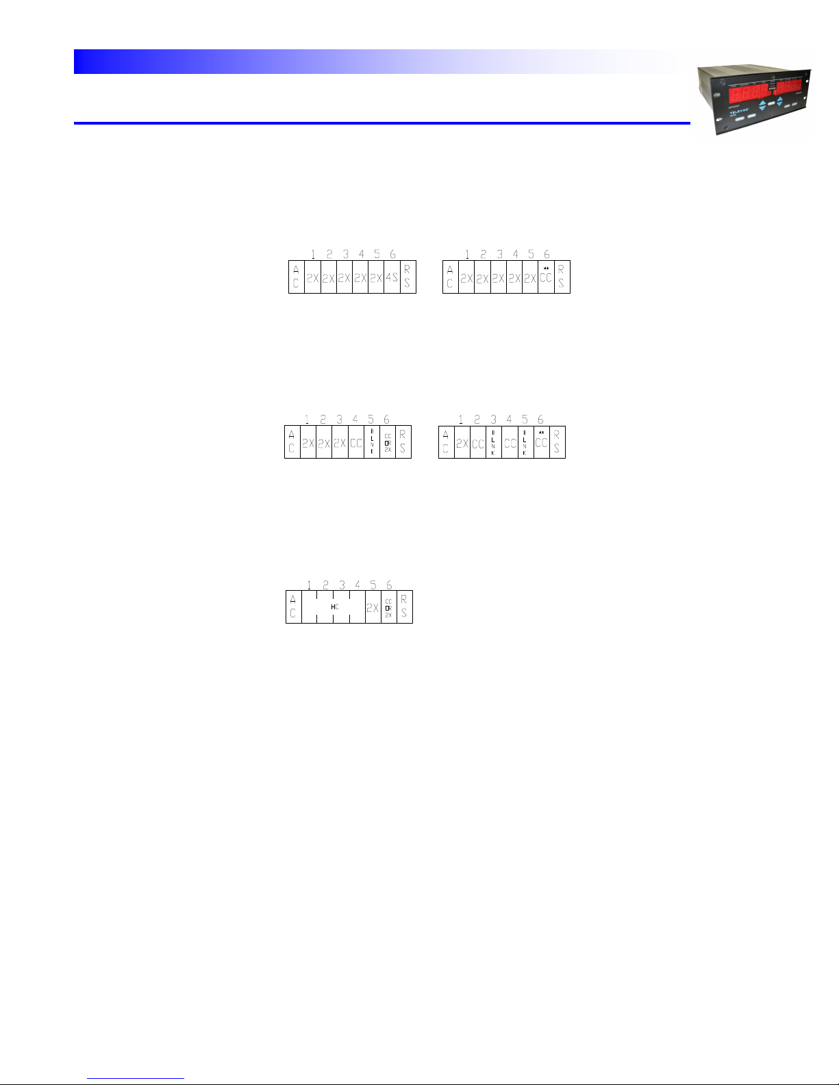
Allowable configurations for the MM200 are shown in
Table 3.1.
160Phone:(215) 947-2500 fax:(215) 947-7464 e-mail:sales@televac.com web site:www.televac.com
MM-200_im REV M
Page 19 of 160
Page 21
TELEVAC
10 8*
9 8*
MAX MAX
# #
STATIONS RELAYS
MAX MAX
# #
STATIONS RELAYS
8 8*
8 4*
MAX MAX
# #
STATIONS RELAYS
5 8*
INSTRUMENT MANUAL
VACUUM GAUGE MODEL MM200
Table 3.1a - Examples of Allowable Configurations for the MM200
MAX MAX MAX MAX
# # # #
STATIONS RELAYS STATIONS RELAYS
EPLANATION OF TERMS USED
2X = Dual station Thermocouple, Convection, Diaphragm, 7F Cold Cathode or single slot 7E cold
cathode
CC = Single station (two slot) Cold Cathode module (** shared space with RS232)
4S = Four setpoint module - * Can substitute for a 2X module
RS = RS232 or RS485
HC = Resident Hot Cathode module
160Phone:(215) 947-2500 fax:(215) 947-7464 e-mail:sales@televac.com web site:www.televac.com
MM-200_im REV M
Page 20 of 160
Page 22
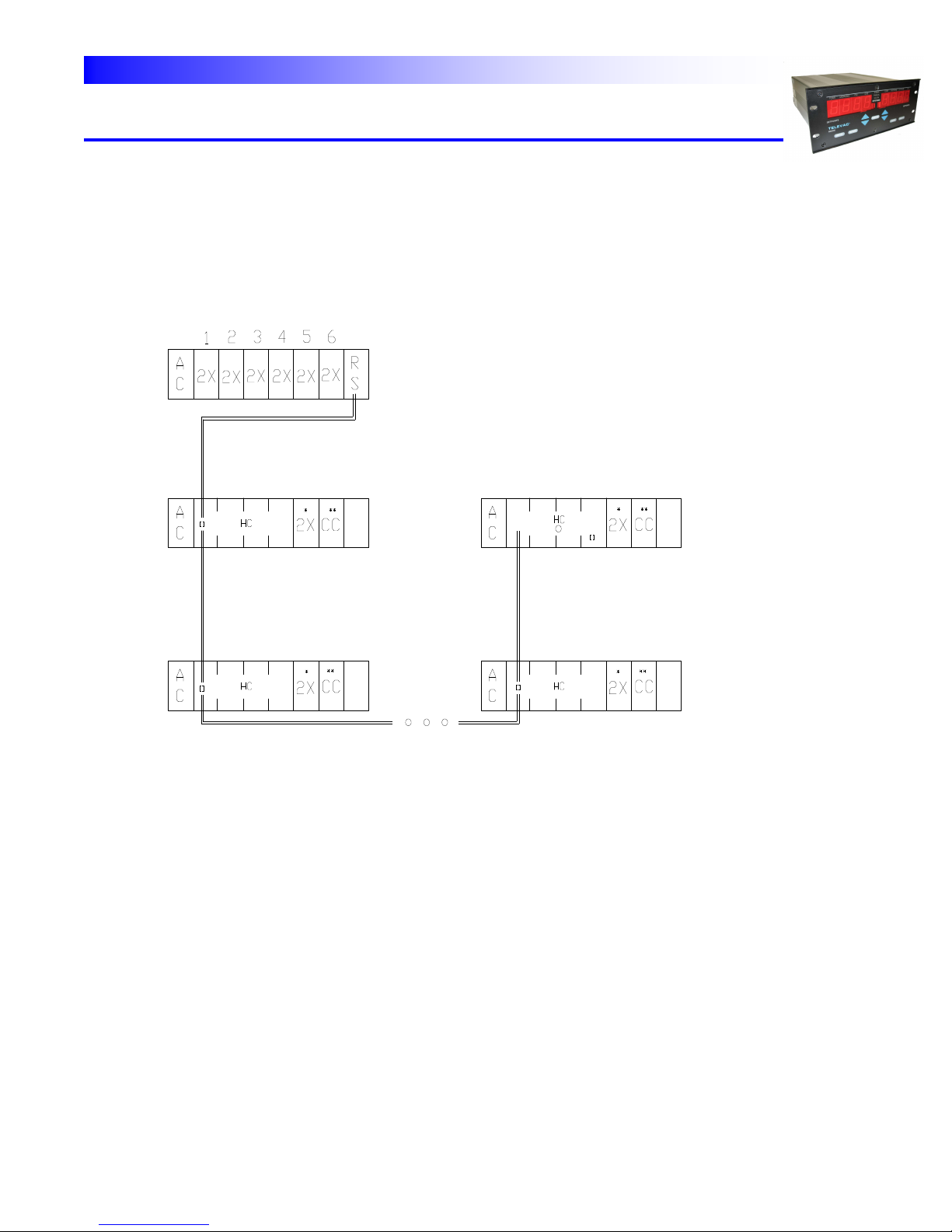
TELEVAC
MM200
MAX MAX
# #
STATIONS RELAY
10
+ 48
8 (SUBSTITUTE 4S FOR 2X)
RS485 LINK TO UP TO
16 REMOTE MODULES
INTERNAL TERMINATION
RESISTOR AT LAST UNIT
Up to 48 remote sensors consisting of
Up to 16 hot cathode remote modules
(with no displays) each with up to
2 additional sensors in a daisy
chain hook up of up to 4000’
* optional local thermocouple,
convection, diaphragm or cold
cathode gauges. Maximum is
2 additional sensors but only 1
cold cathode
REMOTE HOT CATHODE MODULE(S) VIA` MM200
One of several possible combinations using the remote hot cathode module
INSTRUMENT MANUAL
VACUUM GAUGE MODEL MM200
160Phone:(215) 947-2500 fax:(215) 947-7464 e-mail:sales@televac.com web site:www.televac.com
( CONTINUED)
MM-200_im REV M
Page 21 of 160
Page 23
TELEVAC
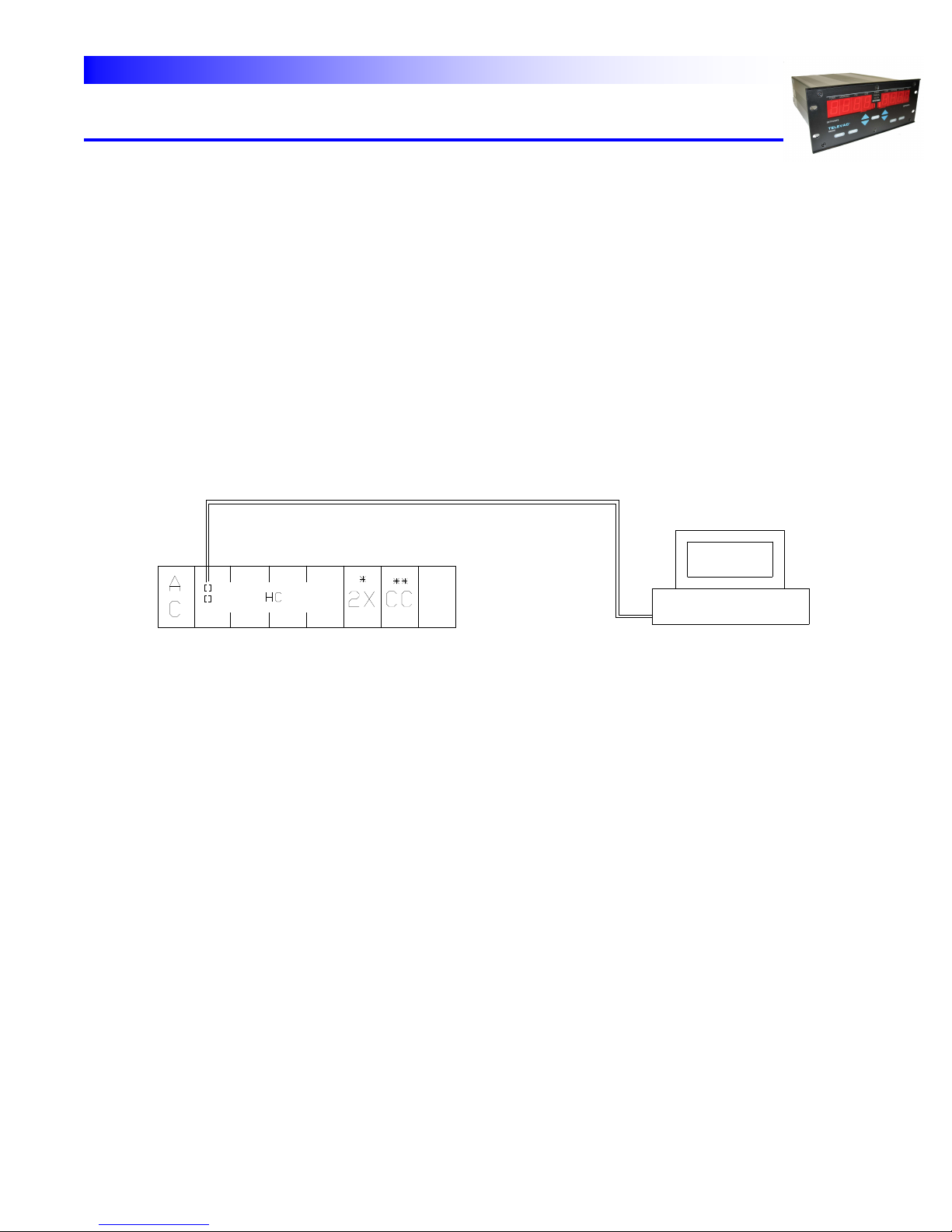
(CONTINUED)
RS232 Link
Computer
* Optional thermocouple, diaphragm,
convection or cold cathode gauges.
Maximum # remote station = 3
Including the hot cathode.
REMOTE HOT CATHODE MODULE(S) VIA COMPUTER
INSTRUMENT MANUAL
VACUUM GAUGE MODEL MM200
Table 3.1c – Allowable Configuration for the MM200 (Continued)
160Phone:(215) 947-2500 fax:(215) 947-7464 e-mail:sales@televac.com web site:www.televac.com
MM-200_im REV M
Page 22 of 160
Page 24
TELEVAC
INSTRUMENT MANUAL
VACUUM GAUGE MODEL MM200
302 LINE VOLTAGE SELECTION
The instruments are shipped from the factory with the line voltage set at 110 for 100-120 VAC operation and
operates at 50-60 Hz. If 200-240 VAC operation is desired, refer to Section 203 for procedure.
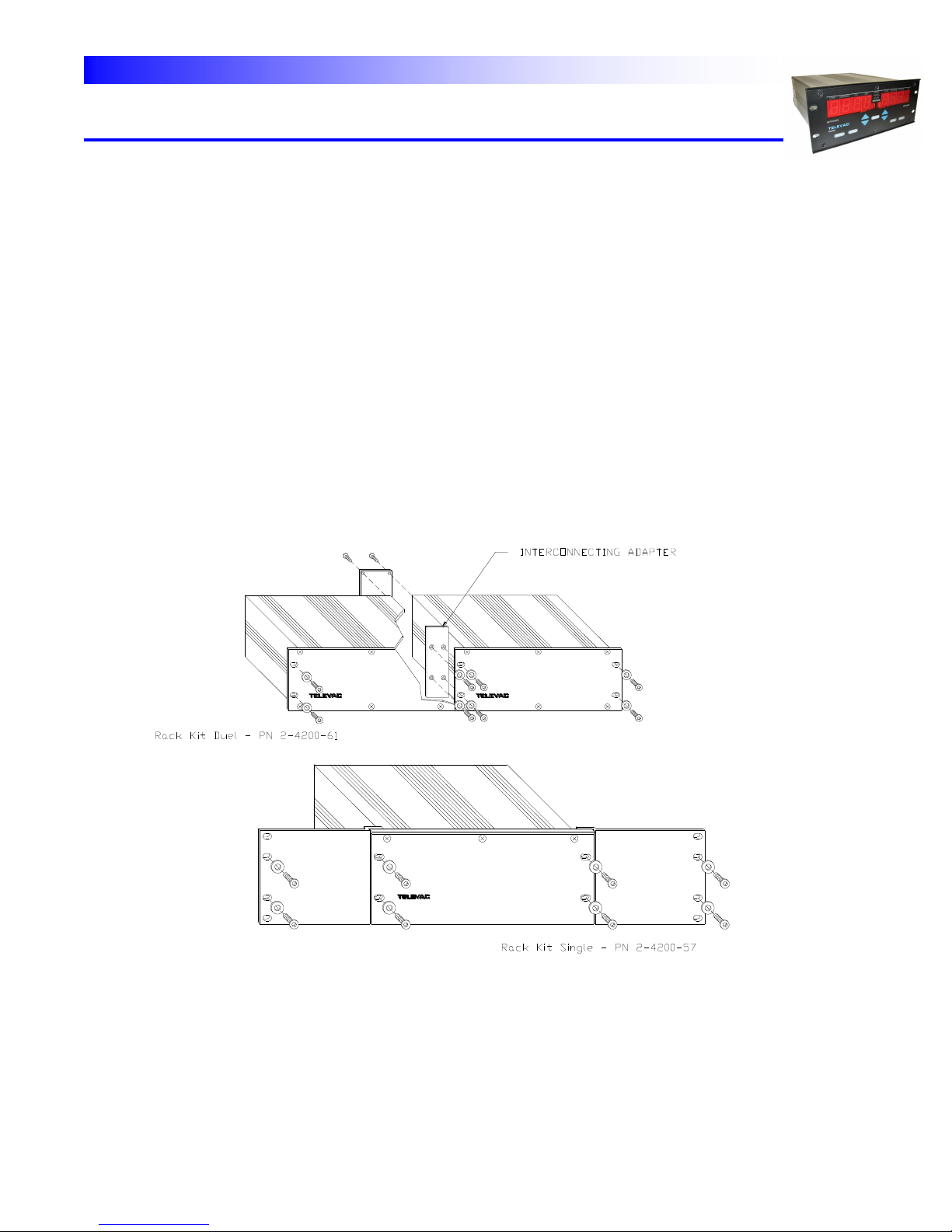
303 GAUGE CONTROLLER INSTALLATION
FREE STANDING
The instrument can be used as a freestanding unit, panel mounted or mounted in a standard 19" rack.
RACK MOUNTED - A rack adapter kit is required to rack mount one or two controllers in a standard 19" rack.
Refer to Fig. 3.2 for component configuration.
For one controller, install the small interconnecting adapter to the unit and then the long filler panel to the interconnecting adapter. Use the four (4) screws, nut and washers provided. Alternately use the adapter fillers.
For two controllers, install the two (2) small interconnecting adapters, in front and in back, between the two units.
Fig. 3.2 – Rack Adapter Details
160Phone:(215) 947-2500 fax:(215) 947-7464 e-mail:sales@televac.com web site:www.televac.com
MM-200_im REV M
Page 23 of 160
Page 25

TELEVAC
INSTRUMENT MANUAL
VACUUM GAUGE MODEL MM200
304 GAUGE SENSOR INSTALLATION WARNINGS
--------------------------------------------------------------------
WARNING: OVERPRESSURE - Do not use quick connects or other friction type connections
where positive pressure exists within sensors, such as in backfilling operations.
--------------------------------------------------------------------
WARNING: SENSOR LOCATION - The gauge sensors should be located as close as possible
to the section of the vacuum system where pressure measurement is important.
Valves or other constrictions between the sensor and the area where pressure
measurement is required may cause erroneous readings or increase the response
time.
--------------------------------------------------------------------
WARNING: CONTAMINATION - Be careful during handling and installation to prevent any
loose debris or contamination of any type from entering the gauge sensors. It is
good practice to not handle the inside surfaces of any vacuum sensor.
--------------------------------------------------------------------
WARNING: Implosion and Explosion - Hot Cathode Ionization Gauges
If handled roughly, glass ionization gauges may implode under vacuum causing
flying glass, which may injure personnel. Be sure that cabling to the gauge tube
has proper strain relief so that cable tension cannot break the glass. If pressurized
above atmospheric pressure, glass tubes may explode, causing dangerous flying
glass. A substantial shield should be placed around vacuum glassware to prevent
injury to personnel.
--------------------------------------------------------------------
WARNING: Temperature - Hot Cathode Ionization Gauges
During degas operations, the envelope of glass ION gauge tubes becomes heated
much more than in normal operation. Be sure that materials that are heat sensitive
are not in contact with the gauge tube, and be sure that the gauge tube is not
located where personnel might come in contact with it.
--------------------------------------------------------------------
CAUTION: Breakage - Hot Cathode Ionization Gauges
If the ConFlat flanges are of the rotatable type, check that the flange bolt ring does
not drop on the glass tube during installation and cause breakage.
--------------------------------------------------------------------
160Phone:(215) 947-2500 fax:(215) 947-7464 e-mail:sales@televac.com web site:www.televac.com
MM-200_im REV M
Page 24 of 160
Page 26

TELEVAC
INSTRUMENT MANUAL
VACUUM GAUGE MODEL MM200
305 VACUUM CONNECTION FITTINGS
Six types of vacuum connection fittings are used in the
gauge system: NPT, O-ring compression, ConFlat flange,
KF, CAJON 8VCR and CAJON 8VCO. (See Table 3.2). A discussion of each is provided below
1. NPT PIPE THREAD CONNECTIONS - These connections should be sealed using vacuum sealing compound
such as TORR-SEAL, Teflon tape or paste. TORR-SEAL is a trademark of Varian Associates Inc.
2. O-RING COMPRESSION FITTINGS - Insert the tubulation of the gauge sensor into the fitting carefully to
avoid damage to the O-ring inside the fitting. The connection is then hand-tightened to create a seal. Do not
over tighten the connection.
If necessary, a small amount of vacuum grease may be used to obtain a good vacuum seal.
3. CONFLAT FLANGE FITTINGS - ConFlat and similar compatible types made by other manufacturers are
widely used for attaching devices to ports on high vacuum systems. These flanges utilize knife-edge surfaces
and compression of copper gaskets to secure a vacuum seal. Be careful not to damage or contaminate the
knife-edges or gaskets during handling operations. (Do not touch copper gasket with hands.) Copper
gaskets should be utilized when high temperature or ultra-high vacuum operation is intended. Tighten all
flange bolts evenly and fully in a crisscross pattern. Do not use copper gaskets more than once. If the flange
is to be baked, pre-lubricate the bolt threads with an antiseize compound (FelPro R C 100 or equivalent).
160Phone:(215) 947-2500 fax:(215) 947-7464 e-mail:sales@televac.com web site:www.televac.com
MM-200_im REV M
Page 25 of 160
Page 27

TELEVAC
INSTRUMENT MANUAL
VACUUM GAUGE MODEL MM200
CAUTION: Be careful that the anti-seize compound does not come in contact with the gaskets or the
vacuum parts of the flange.
4. KF FLANGE CONNECTIONS - These connections consist of a centering ring and clamp. The centering ring
is self-centering and aids in alignment. The clamps should be finger-tightened until both flanges are firmly in
contact with the O-ring seal.
Use a new gasket whenever the gauge is reconnected, unless gasket retainer assemblies are used.
5 CAJON FITTINGS - If necessary, a small amount of vacuum grease may be used on the O-ring to obtain a
good seal.
306 GAUGE SENSOR INSTALLATION (Refer to Table 3.3 for Gauge Sensor Installation)
Table 3.3 - Gauge Sensor Installation
GAUGE
TYPE MOUNTING INLET
ORIENTATION
Diaphragm A Vertical, down, desired
Convection A Vertical, down, required
Thermocouple A Vertical, down, desired
Cold Cathode B NA
Hot Cathode-glass C Horizontal
Hot Cathode-nude C NA
A - To prevent debris from entering the gauge sensor and to provide the highest accuracy, it is recommended that
the gauge sensor be installed with its main body vertical. Do not mount the sensor in areas where gases are
allowed to stream directly into the gauge tube since damage to the filament could result. Install cable to sensor and
chassis sockets. Connector is keyed to provide proper orientation at the sensor socket. Do not force connector
into socket.
B - The gauge sensor can be mounted in any position. The magnet should not be closer than 1" to any magnetic
material. Additionally, when mounting the sensor take into account that the field of the gauge magnet may disturb
beams of charged particles in the vacuum system. Install shielded high-voltage BNC connector to gauge and
chassis sockets before turning on the power.
C - The gauge sensor can be mounted in any position. It is important that gauge have good
communication with the vacuum space for accurate pressure readings, especially at lower pressures.
160Phone:(215) 947-2500 fax:(215) 947-7464 e-mail:sales@televac.com web site:www.televac.com
MM-200_im REV M
Page 26 of 160
Page 28
TELEVAC
INSTRUMENT MANUAL
VACUUM GAUGE MODEL MM200
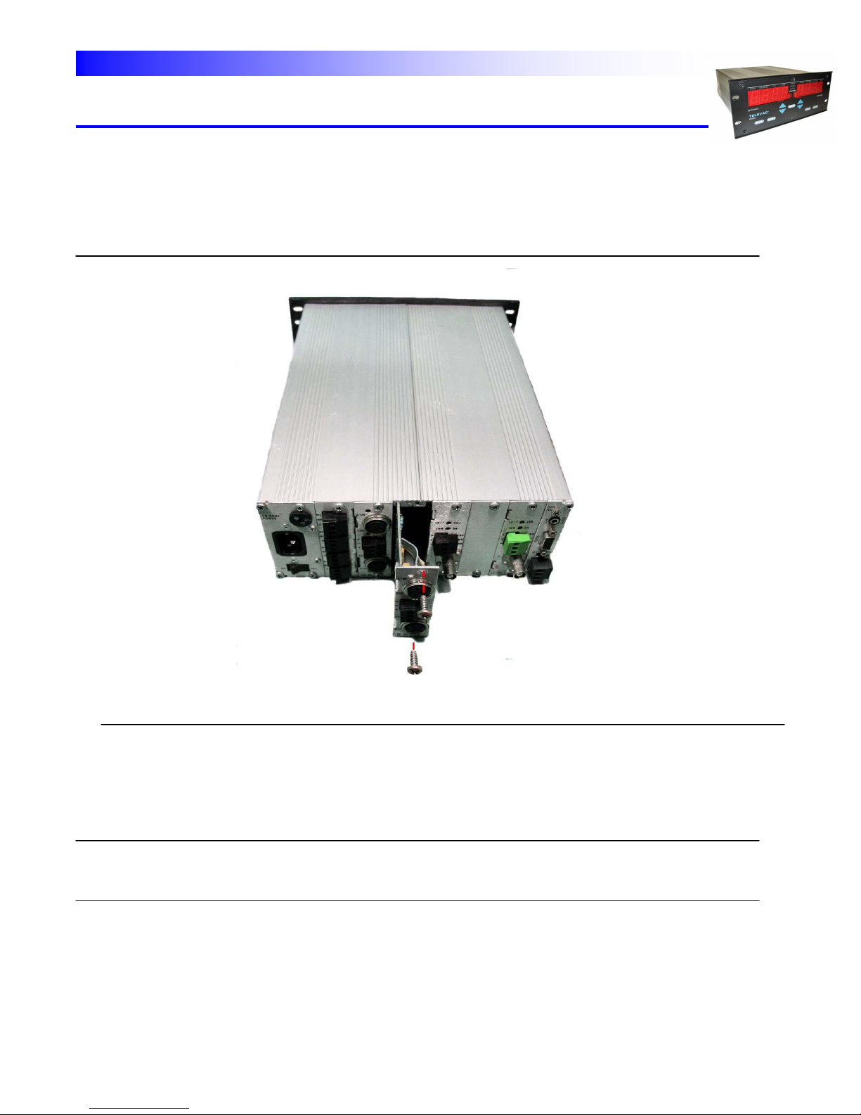
307 REMOVAL AND INSTALLATION OF MODULES
Mounting screws are located at the top and the bottom of each module. To remove a module, remove both screws
and pull on the rear panel of the module. If necessary, use a small screwdriver to start the module moving by
prying between the module and the enclosure. The module will then slide out easily (See Fig. 3.3).
Fig. 3.3 - Removal / Installation of Modules
To install a module, slide it in place along the track and firmly press it into the mating socket connector. Reinstall
screws.
If you wish to add optional modules, install them as outlined below:
WARNING: TO AVOID POSSIBLE SHOCK, DISCONNECT THE POWER CORD FROM THE
CONTROLLER.
160Phone:(215) 947-2500 fax:(215) 947-7464 e-mail:sales@televac.com web site:www.televac.com
MM-200_im REV M
Page 27 of 160
Page 29
TELEVAC
INSTRUMENT MANUAL
VACUUM GAUGE MODEL MM200
1. Remove the sensor interface module from its packaging. Examine it for shipping damage. If damaged,
refer to Section 201.
2. Place jumpers in the desired position to select station numbers, setpoint station assignment, etc. as
described in Section 902.
3. Remove the two screws holding the blank cover plate over the module position you plan to use.
4. Align the module with the slots in the instrument and push into place. Press to secure edge connector into
the connector on the motherboard.
5. Reinstall the two screws.
308 DESCRIPTION OF MODULES
Various types of modules are available for installation in
the MM200 gauge. Descriptions of available modules follow as they appear from the rear panel. For detailed
descriptions of available modules and their setup, see Section 902.
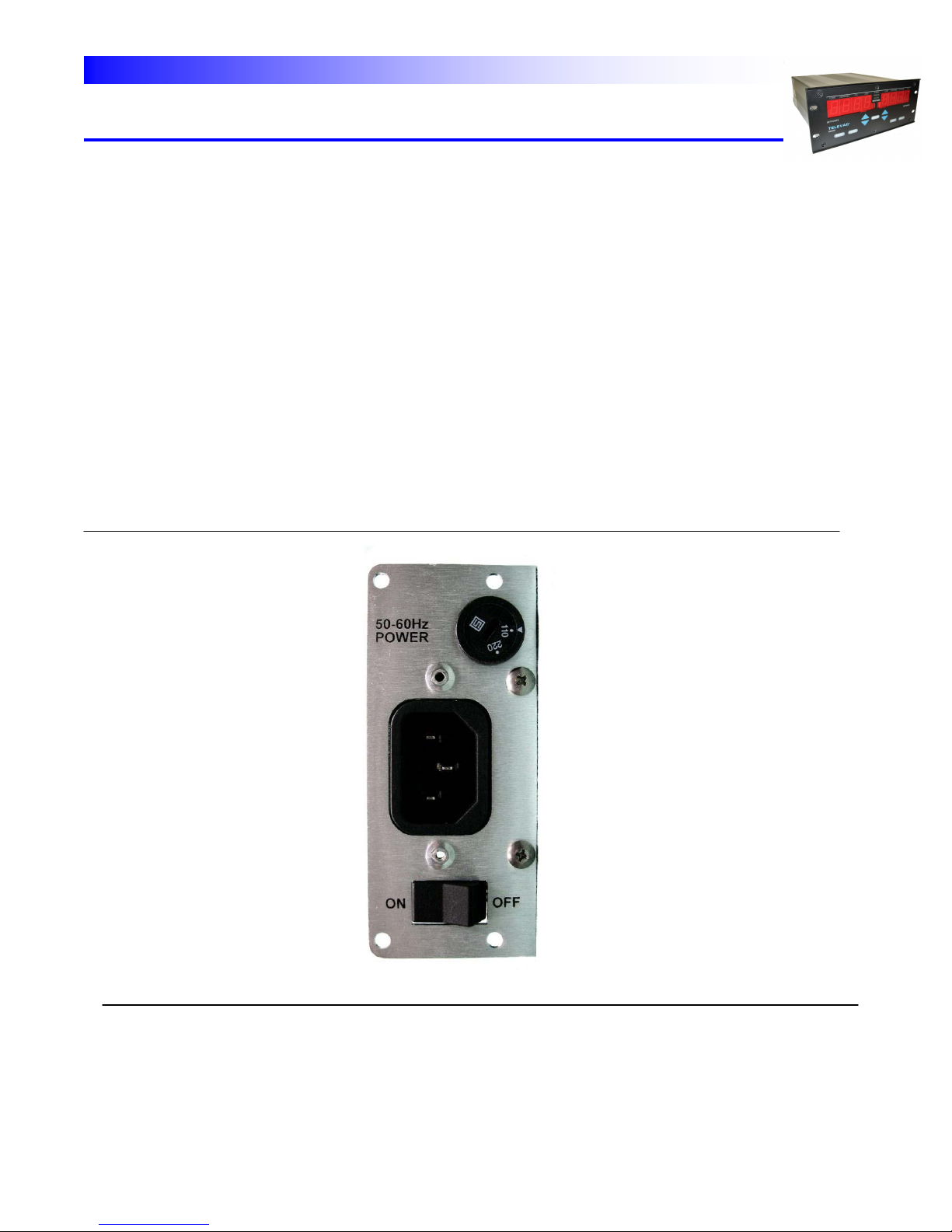
POWER SUPPLY MODULE - The power supply module is located in module slot "0" on the left rear of the
instrument. It contains a plug socket for the power cord, a voltage selection switch and an on/off switch. (Fig. 3.4).
Fig. 3.4 - Power Supply Module
160Phone:(215) 947-2500 fax:(215) 947-7464 e-mail:sales@televac.com web site:www.televac.com
MM-200_im REV M
Page 28 of 160
Page 30
TELEVAC
TOP
MID1
MID2
BOTTOM
INSTRUMENT MANUAL
VACUUM GAUGE MODEL MM200
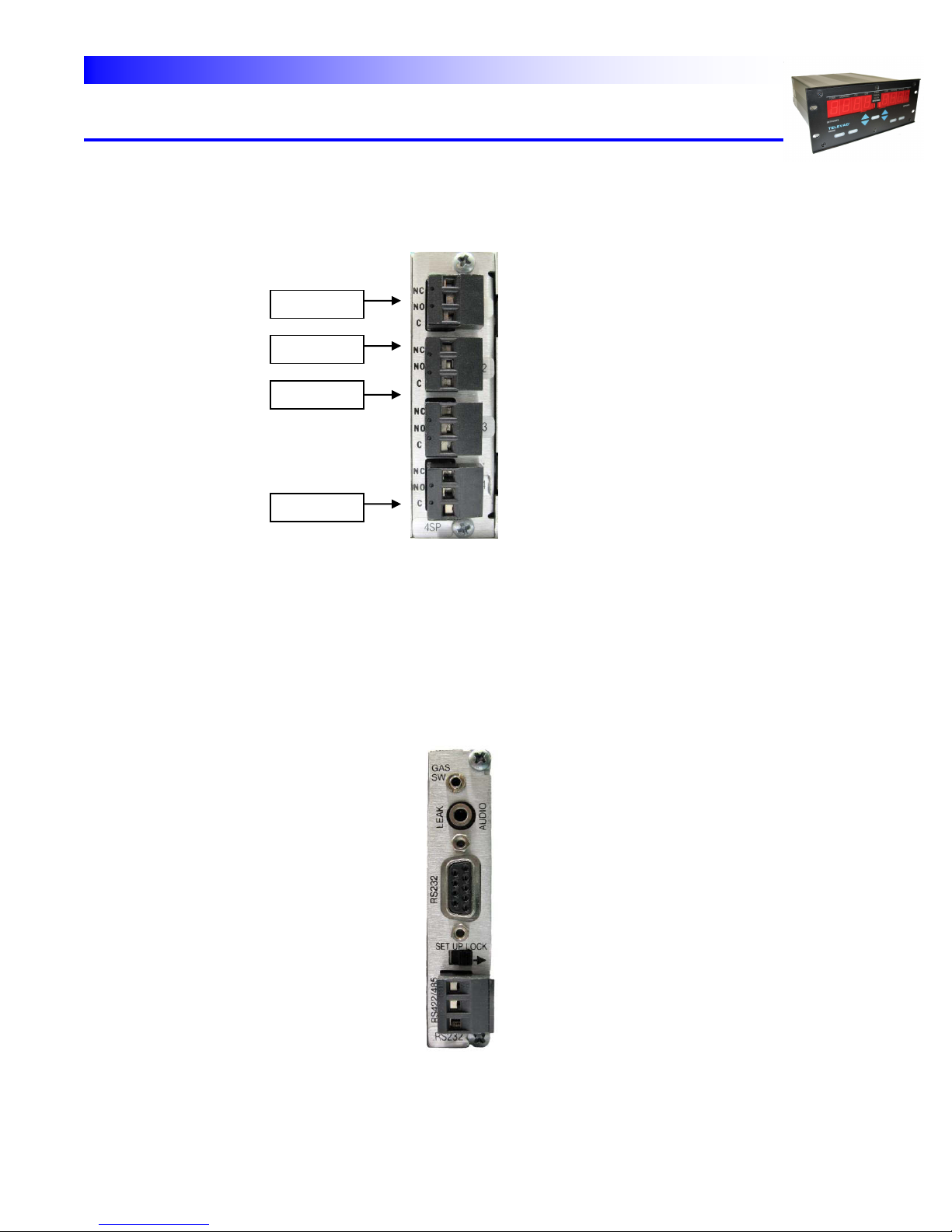
SETPOINT RELAY MODULE - The rear panel of the setpoint process control relay module is shown in Fig. 3.5.
Three (3) terminals are available for each of the four (4) relays. These are NC (Normally Closed), NO (Normally
Open) and C (Common).
Fig. 3.5 - Rear Panel of the Setpoint Relay Module
COMMUNICATIONS MODULE - The rear panel of the module is shown in Fig. 3.6. It features a DE9S (female)
connector for the RS232 or RS485 interface cable. A SETUP lock switch is used to permit or to lock out the
capability to reset or reassign relays using the SETUP function. Two (2) phone jacks are also shown. The larger
one (3.5 mm) is labeled LEAK AUDIO and is used to provide an audible signal whose pitch (frequency) is a function
of the instantaneous pressure. The smaller one (2.5 mm) is labeled GAS SW and is used to remotely switch the
display to the "alternative gas" (See Section 401). See Figure 9.2 for RS485 termination. An alternate function
provided by the smaller phone jack is to accept an enable 24-volt signal that would prevent operation of ion type
gauges if not present.
Fig. 3.6 - Rear Panel of the Communications Module
160Phone:(215) 947-2500 fax:(215) 947-7464 e-mail:sales@televac.com web site:www.televac.com
MM-200_im REV M
Page 29 of 160
Page 31

TELEVAC
INSTALLATION SCREW
UPPER AND LOWER
SENSOR ID NUMBER
[FIVE] *
FOUR PIN
CONNECTOR
(FEMALE)
SPAN OR
ATMOSPHERE ADJUST
(DIAPHRAGM, CONVECTION, CDG)*
ZERO ADJUST
0-10V OUTPUT
DI 1E
TC 2A
CV 4A
CDG
XXX
INSTRUMENT MANUAL
VACUUM GAUGE MODEL MM200
THERMOCOUPLE MODULE - The rear panel of the thermocouple module is shown in Fig. 3.7. The gauge tube
cables can be connected by inserting the cable connector into the socket and turning the shell clockwise to engage
the screw threads for retention of the connector.
The thermocouple module is designed to work with the type 2A thermocouple gauge tube. Special electronics have
been added to the 2A thermocouple module to allow the 2A gauge tube to operate up to 20 Torr (20,000 microns).
An analog "0-10V" output (normally 0 to 10VDC) is available at the connector in the center of the panel. This
output covers the range of 0 to 1000 microns only in order to give good definition to the data in this lower range.
Other outputs are also available. An optional 0 to 10 mVDC is also available (See Section 902). There are three
terminals available. The center terminal is a common ground and negative terminal for both the upper and lower
thermocouple stations. The upper and lower terminals are the positive signals for the upper and lower stations,
respectively.
Between the cable connector and the analog “0-10V” output terminal is a "zero" potentiometer for the thermocouple
gauge tube. This potentiometer is used, if required, to adjust the current to the thermocouple sensor "heater",
which can be used to compensate, over a limited range, for effects of contamination from the process in the
vacuum chamber. The ATM adjust is not used for the thermocouple gauges.
Fig. 3.7 - Rear Panel of the Thermocouple, Convection and Diaphragm Modules
160Phone:(215) 947-2500 fax:(215) 947-7464 e-mail:sales@televac.com web site:www.televac.com
MM-200_im REV M
Page 30 of 160
Page 32

TELEVAC
INSTRUMENT MANUAL
VACUUM GAUGE MODEL MM200
CONVECTION MODULE - The rear panel of the convection module is also shown in Fig. 3.7. The only difference
that can be seen from the rear panel is the use of the letters CV instead of TC. The gauge tube cables can be
connected by inserting the cable connector into the socket and turning the shell clockwise to engage the screw
threads for retention of the connector. Note that the convection cable has different wiring and markings from the
thermocouple cable.
The convection module is designed to work with the type 4A convection gauge tube. Special electronics have been
provided in the 4A convection module to allow it to operate up to above atmospheric pressure (approximately 1000
Torr).
An analog "0-10V " output (normally 0 to 10VDC) is available at the connector in the center of the panel. This
output covers the range of 10-3 to 10+3 Torr. An a optional 0 to 10 mvDC is also available (See Section 902). There
are three terminals available. The center terminal is a common ground and negative terminal for both the upper
and lower convection stations. The upper and lower terminals are the positive signals for the upper and lower
stations, respectively.
Between the cable connector and the analog "0-10V " output terminal is a ZERO potentiometer for the convection
gauge tube. This potentiometer is used, if required, to adjust the zero at 1 x 10⁻⁵ Torr. It can be used to
compensate, over a limited range, for effects of contamination from the process in the vacuum chamber. A second
potentiometer marked ATM is used to adjust the gauge at atmospheric pressure. This should be set the known
value of absolute atmospheric pressure on the gauge - not referred to sea level as is used by the weather bureau
or airports.
DIAPHRAGM MODULES - The rear panel of the diaphragm modules are also shown in Fig. 3.7. The only
difference that can be seen from the rear panel of a thermocouple module is the use of the letters DI instead of TC
and the presence of a SPAN potentiometer. The gauge tube cables can be connected by inserting the cable
connector into the socket and turning the shell clockwise to engage the screw threads for retention of the
connector. Note that the diaphragm cables have different wiring and markings from the thermocouple cable.
The diaphragm modules are designed to work with the type 1E or 1F diaphragm gauge tubes.
Range 1E: 1 to 1000 Torr; 1F: 1000 to 9999 mbar.
An analog "0-10V " output (normally 0 to 10VDC) is available at the connector in the center of the panel. An
optional 0 to 10 mvDC is also available (See Section 902). There are three terminals available. The center terminal
is a common ground and negative terminal for both the upper and lower diaphragm stations. The upper and lower
terminals are the positive signals for the upper and lower stations, respectively.
Between the cable connector and the analog "0-10V” output terminal is a ZERO potentiometer. This potentiometer
is used, if required, to adjust the zero at a pressure two decades below the lower limit of the gauge. It can be used
to compensate, over a limited range, for effects of contamination from the process in the vacuum chamber. A
second SPAN potentiometer is used to adjust the 1E gauge at atmospheric pressure or the 1F gauge at 10,0000
mbar. A known value of absolute atmospheric pressure - not referred to sea level should be used for setting the
1E.
160Phone:(215) 947-2500 fax:(215) 947-7464 e-mail:sales@televac.com web site:www.televac.com
MM-200_im REV M
Page 31 of 160
Page 33

TELEVAC
ADJUST
ANALOG OUTPUT
COLD CATHODE
CABLE CONNECTION
INSTRUMENT MANUAL
VACUUM GAUGE MODEL MM200
COLD CATHODE MODULE - The rear panel of the cold cathode module is shown in Fig. 3.8. The gauge tube
cables can be connected by inserting the cable connector into the socket and turning the shell clockwise to engage
the lugs for retention of the connector. An analog output (normally 0 to 10VDC) is available at the connector in the
center of the panel. There are three terminals available. The lower terminal is a common ground and negative
terminal for both the upper two terminals. The upper two terminals are for + 10 volts and + 10 millivolts
respectively. Above the analog “0-10V " output terminal is a 10-3, a 10-5 or a span adjust potentiometer. These
potentiometers are used, if required, for calibration and to compensate, over a limited range, for effects of
contamination from the process in the vacuum chamber. There is a phone jack labeled “starter” above the
potentiometers for the 7FCS 6200-285 module only. The "ION-ON" potentiometer is not used for the MM200 and its
setting is ignored.
Fig. 3.8 - Rear Panel of the Cold Cathode Gauge Module
3D HOT CATHODE RESIDENT MODULE (I2 R DEGAS) - The rear panel of the 3D hot cathode resident module
with resistive (I2 R) degas is shown in Fig. 3.9. This module occupies 4 module slots. The module must be within
10' (100' with a special cable) of the sensor (gauge tube). No station should be numbered higher than #5.
The sensor power and control cable is connected to the socket in lower right-hand side of the module. Push plug
straight in until the connector "clicks" into a locked position. To remove, press on the sides of the connector, until
the locks are released, and then pull straight out. The sensor ion collector cable is connected to the module via a
BNC connector located in the left-hand middle of the module. Push the mating connector in and twist clockwise to
secure. Above the BNC connector is a case ground connection used to connect the unit independently to a "good
earth ground". Below the BNC connector is a switch marked TUBE TYPE and above the sensor power cable
connector is a sensitivity selector switch. For use see Table 3.4.
160Phone:(215) 947-2500 fax:(215) 947-7464 e-mail:sales@televac.com web site:www.televac.com
MM-200_im REV M
Page 32 of 160
Page 34

TELEVAC
INSTRUMENT MANUAL
VACUUM GAUGE MODEL MM200
Table 3.4 Tube Type
Rotary Sensitivity Sensitivity Glass Tube Nude Tube
Switch Switch
0 10/12.5 12.5 Plain 2160-1xx
1 10/12.5 12.5 Coated 2162-1xx
2 10/12.5 10 Plain 2161-2xx I2R 2164-352
3 10/12.5 10 Coated 2163-2xx
0 20/25 25 Plain EB 2166-452
1 20/25 25 Coated
2 20/25 20 Plain
3 20/25 20 Coated
Note: Switch position with power off or turn power ON/OFF after switching.
There is no filament selector switch for use with dual filament sensors on this unit as this is done through front
panel commands. It is necessary to switch the filaments when the filament power is off. It may also be necessary
to reverse the cable connector.
An analog output is available at the connector in the lower left of the panel. There are three terminals available.
The lower terminal is a common ground and negative terminal for both the upper two terminals. The upper two
terminals are for + 10 volts and + 10 millivolts respectively.
Refer to Section 502.3 Hot Cathode Setup for further information.
Fig. 3.09 Rear Panel of the Resident 3E Hot Cathode Gauge Module
160Phone:(215) 947-2500 fax:(215) 947-7464 e-mail:sales@televac.com web site:www.televac.com
MM-200_im REV M
Page 33 of 160
Page 35

TELEVAC
INSTRUMENT MANUAL
VACUUM GAUGE MODEL MM200
3E HOT CATHODE RESIDENT MODULE (EB DEGAS) - The rear panel of the 3E hot cathode resident module
with electron beam (EB) degas is shown in Fig. 3.9. This module occupies 4 module slots. The module must be
within 10' (100' with a special cable) of the sensor (gauge tube). No station should be numbered higher than #5.
The sensor power and control cable is connected to the socket in lower right-hand side of the module. Push plug
straight in until the connector "clicks" into a locked position. To remove, press on the sides of the connector, until
the locks are released, and then pull straight out. The sensor ion collector cable is connected to the module via a
BNC connector located in the left-hand middle of the module. Push the mating connector in and twist clockwise to
secure.
Above the BNC connector is a case ground connection used to connect the unit independently to a "good earth
ground".
Below the BNC connector is a switch marked TUBE TYPE. Switch position with power off or turn power ON/OFF
after switching. See Table 3.4.
An analog output is available at the connector in the lower left of the panel. There are three terminals available.
The lower terminal is a common ground and negative terminal for both the upper two terminals. The upper two
terminals are for + 10 volts and + 10 millivolts respectively.
There is no filament selector switch for use with dual filament sensors on this unit as this is done through front
panel commands. It is necessary to switch the filaments when the filament power is off.
Refer to Section 502.3 Hot Cathode SETUP for further information.
Fig. 3.10 Rear Panel of the Resident 3E Hot Cathode Gauge Module
160Phone:(215) 947-2500 fax:(215) 947-7464 e-mail:sales@televac.com web site:www.televac.com
MM-200_im REV M
Page 34 of 160
Page 36

TELEVAC
INSTRUMENT MANUAL
VACUUM GAUGE MODEL MM200
3F HOT CATHODE MINI-BA MODULE (Software ver. 2.31 or higher) - The 3F hot cathode mini-BA module
occupies 2 slots inside the mm200 unit. If one module is to be installed, it must be configured to station 5. If a
second module is to be installed, it must be configured to station 6.
Place 5 jumpers vertically for station 5. If two 3F hot cathode mini-BA modules are to be used, place 5 jumpers
vertically in station 6 for the second module.
When installing the modules into the unit, make sure that the card edge fingers align with the connectors inside the
unit. Make sure that the module is properly seated in the connectors then install the 4 screws per module in the
back panel.
160Phone:(215) 947-2500 fax:(215) 947-7464 e-mail:sales@televac.com web site:www.televac.com
MM-200_im REV M
Page 35 of 160
Page 37

TELEVAC
INSTRUMENT MANUAL
VACUUM GAUGE MODEL MM200
(Software ver. 2.31 or higher)
The rear panel of the hot cathode mini-BA module is shown below. The gauge tube cables are connected to the ion
collector and the 9-pin ion gauge connector. An analog output (normally 0 to 10 VDC) is available at the connector
in the upper right as shown below. There are three terminals available. The lower terminal is a common ground and
negative terminal for both the upper two terminals. The upper two terminals are for +10 volts and +10 millivolts
respectively.
3F hot cathode mini-BA back panel
160Phone:(215) 947-2500 fax:(215) 947-7464 e-mail:sales@televac.com web site:www.televac.com
MM-200_im REV M
Page 36 of 160
Page 38

TELEVAC
INSTRUMENT MANUAL
VACUUM GAUGE MODEL MM200
Software ver. 2.31 or higher)
MINI-BA GAUGE TO 3F MODULE WIRING DIAGRAM
160Phone:(215) 947-2500 fax:(215) 947-7464 e-mail:sales@televac.com web site:www.televac.com
MM-200_im REV M
Page 37 of 160
Page 39

TELEVAC
NOTE:
Capacitance Diaphragm Gauge Tubes with a range of greater than 1 Torr will not control the Cold
Cathode automatic turn on!
INSTRUMENT MANUAL
VACUUM GAUGE MODEL MM200
CAPACITANCE DIAPHRAGM MODULES - The rear panel of the capacitance diaphragm modules are also
shown in Fig. 3.7. The only difference that can be seen from the rear panel of a thermocouple module is the use of
the letters CDG instead of TC and the presence of a SPAN potentiometer. The gauge tube cables can be
connected by inserting the 5-pin cable connector into the socket and turning the shell clockwise to engage the
screw threads for retention of the connector. Note that the capacitance diaphragm cables have different wiring and
markings from the thermocouple cable.
The capacitance diaphragm modules are designed to work with the type 5__ capacitance diaphragm gauge tubes.
Ranges are as follows:
SOFT 1.33 AND LOWER SOFT 1.34 AND HIGHER
Full Scale: Full Scale:
5A: 1 Torr 5A: 1000 Torr
5B: 1000 Torr 5B: 100 Torr
5C: 10 Torr 5C: 10 Torr
5D: 1 Torr
5E: 0.1 Torr
5F: special
An analog "0-10V" output (normally 0 to 10VDC) is available at the connector in the center of the panel. An
optional 0 to 10 mvDC is also available (See Section 902). There are three terminals available. The center terminal
is a common ground and negative terminal for both the upper and lower diaphragm stations. The upper and lower
terminals are the positive signals for the upper and lower stations, respectively.
Between the cable connector and the analog "0-10V " output terminal is a ZERO potentiometer. This potentiometer
is used, if required, to adjust the zero at a pressure two decades below the lower limit of the gauge. A second
SPAN potentiometer is used to adjust the 5__ capacitance diaphragm gauge at the maximum (full scale) value for
the sensor.
160Phone:(215) 947-2500 fax:(215) 947-7464 e-mail:sales@televac.com web site:www.televac.com
MM-200_im REV M
Page 38 of 160
Page 40

TELEVAC
INSTRUMENT MANUAL
VACUUM GAUGE MODEL MM200
160Phone:(215) 947-2500 fax:(215) 947-7464 e-mail:sales@televac.com web site:www.televac.com
MM-200_im REV M
Page 39 of 160
Page 41

TELEVAC
STATION NUMBER
MEASURING
UNITS
MEASURING
UNITS
MEASURING
UNITS
INSTRUMENT MANUAL
VACUUM GAUGE MODEL MM200
400 OPERATION
Turn the power switch, located on the rear panel, to the ON position. If the gauge is installed in a rack or cabinet
where the power switch is not accessible, power may be left on without damage to the instrument.
401 DISPLAY DESCRIPTION AND DEFINITIONS
Fig. 4.1 shows the front panel of the gauge controller with all LED segments displayed. A definition of each display
is provided.
STATION NUMBER - This number corresponds to the sensor whose pressure (vacuum) is being displayed. This
sensor is located at a particular location in the vacuum system.
Figure 4.1 - Front Panel of Gauge Controller
The gauge controller can have one (1) to ten (10) stations. The station numbers are normally factory assigned but
can be re-assigned at installation. Stations are selected via the UP/DOWN arrows. The 10 th station, if installed, is
indicated by an "A".
DATA DISPLAY - The simultaneous display of two stations each present 4 digits of measurement (normally for
thermocouple #1 and the primary ionization gauge - cold cathode or hot cathode). It can also display programming
data for the station or setpoint selected via the UP/DOWN
160Phone:(215) 947-2500 fax:(215) 947-7464 e-mail:sales@televac.com web site:www.televac.com
MM-200_im REV M
Page 40 of 160
Page 42

TELEVAC
INSTRUMENT MANUAL
VACUUM GAUGE MODEL MM200
pushbuttons. The ionization gauge display flashes "OFF" until it is turned on by the controlling thermocouple
station (usually TC#1). The high voltage to the gauge tube will be off during this time.
Normally, the thermocouple station data are indicated in microns in a numerical format for pressures above 1
micron. The ionization gauge stations are indicated in Torr below 1 micron (10-3 Torr) using an exponential format.
In the exponential format, positive and negative exponent can be used. The display of negative and positive
exponents is done as follows:
3.0 x 10⁻⁷ is displayed as 3.0-7
3.0 x 10+2 is displayed as 3.0E2
UNITS: TORR, MICRONS, MBAR, PA, PSI - Use the UNITS pushbutton to select the desired pressure
measurement unit to be displayed. Also available is MICRONS per HR used for leak rate and, in the future,
SCC/M for flow rate display.
GAS TYPE: (N2 or GAS) - These abbreviations indicate the gas type that is being measured by the selected
sensor. The gas type has been selected by the operator via front panel programming using the N2/GAS
pushbutton. The alternate gas type is factory programmed and is typically argon. Display letters periodically flash
ArG (for argon) and He (for helium gas). Other gas types may be available on special order.
LEAK RATE INDICATOR - This is a trend representation of displayed data and indicates the rate of change of
pressure. Full scale is approximately 9999 microns/hour. A positive number indicates pressure increases, a
negative number indicates pressure decreases. This feature is activated via the LEAK RT pushbutton.
SETPOINT RELAY STATUS NUMBERS - The setpoint relay status lights show the status of each relay. If the
number is illuminated, then the relay has been energized due to the pressure on the assigned sensor falling below
the "on" setpoint. These numbers are not lighted during the self-diagnostic function. They are out during the
initialization routine after power-up. Relays are located on the optional setpoint module board.
402 ERROR INDICATIONS
Using internal diagnostics, the gauge software system continuously monitors the unit to verify proper operating
conditions during power-up and normal operations. Any error conditions that are detected are displayed on the
LED in the form of an error code message reading "Err" in the data display. This display comes up automatically
after power-up or whenever the self-diagnostic test is run. The display also indicates the particular error condition
detected. Refer to Section 502.1 for a more detailed explanation of error messages.
160Phone:(215) 947-2500 fax:(215) 947-7464 e-mail:sales@televac.com web site:www.televac.com
MM-200_im REV M
Page 41 of 160
Page 43

TELEVAC
1 2 3 4 5
6
INSTRUMENT MANUAL
VACUUM GAUGE MODEL MM200
403 KEYPAD DESCRIPTION
Fig. 4.2 shows the front panel of the gauge controller with the various control pushbuttons identified.
Fig. 4.2 - Control Pushbuttons
160Phone:(215) 947-2500 fax:(215) 947-7464 e-mail:sales@televac.com web site:www.televac.com
MM-200_im REV M
Page 42 of 160
Page 44

TELEVAC
INSTRUMENT MANUAL
VACUUM GAUGE MODEL MM200
PUSHBUTTON FUNCTIONS
1. TEST/OP PUSHBUTTON - Returns the instrument to normal operation at any time when in the SETUP
mode. Initiates the Self-diagnostic test.
2. SETUP PUSHBUTTON - Allows PCR upper and lower setpoints to be viewed. Allows UP/DOWN arrows
to raise or lower setpoints unless the SETUP switch on the optional RS232 module is in the LOCK position.
3. N2/GAS PUSHBUTTON - Change gauge sensitivity to correspond to a gas other than air or nitrogen (N2).
Gauges other than diaphragm types respond differently to different gases. (See Section 700). The program uses
argon for the other gas unless otherwise programmed at factory. This function is inhibited when the SETUP switch
on the optional RS232 module is in the LOCK position. (Also see Section 502.5).
4. UP/DOWN ARROWS - Incrementally increase or decrease the number of the stations being displayed.
Increases or decreases the PCR setpoint values when the lockout switch is in the ENABLE position; reassigns set
point assignments. (See Section 502 for details).
5. UNITS PUSHBUTTON - Changes units of measurement for pressure from the default units to: TORR,
MICRON, PSI, MBAR, PASCAL. This does NOT change the analog 0-10V output values.
6. LEAK RT PUSH BUTTON - After a 15 second delay, displays average leak rate (or rate of change of
pressure) in the right hand display when depressed. Display is in MICRONS per HR.
404 RELAY SETPOINTS
Relay setpoints are used to control the four relay outputs located on the optional Setpoint Relay Module. Each
relay has a pair of setpoints, an upper and a lower value. These setpoints correspond to the pressure value of a
specified sensor. The relay is energized when the pressure goes below the "on" setpoint, and de-energized when
the pressure goes above the "OFF" setpoint. When the pressure is between the two setpoints, the relay remains in
its current state. To adjust the setpoints see Section 502.
Since the relays have a flash coating of gold, they can be used as either "dry circuit" (low power) or power relays
(up to 5 Amps). Use of the relay as a power relay forever impairs its use as a "dry circuit" relay.
The RELAY messages on the display indicate the status of the relays. If the RELAY is energized, the
corresponding relay number light is on. If it is de-energized, the light is off.
160Phone:(215) 947-2500 fax:(215) 947-7464 e-mail:sales@televac.com web site:www.televac.com
MM-200_im REV M
Page 43 of 160
Page 45

TELEVAC
INSTRUMENT MANUAL
VACUUM GAUGE MODEL MM200
RANGE OF USE
For relays assigned to the following types of sensors:
Cold Cathode - any value up to 10-2 Torr
Convection - 1 micron to 990 Torr
Diaphragm - 1 to 990 Torr
Hot Cathode - any value up to 10-2 Torr
Thermocouple - 1 micron to 3 Torr.
Settings above 3 Torr, if required, will have to be set experimentally and will differ depending on whether
the pressure is increasing or decreasing.
CHANGING SENSOR ASSIGNMENT
When changing sensor assignment TO A DIFFERENT TYPE OF SENSOR the following step must be taken to
assure proper operation:
Use the DOWN ARROW to RUN THE SET POINT TO ZERO BEFORE RESETTING IT to the desired setpoint.
Example 1: Controlling a Cross-over Valve.
Cross-over is the point at which the high vacuum pump (e.g., diffusion pump) is connected to
the vacuum system. This is usually done automatically at a pressure in the range of 80 to
100 microns.
Relay 1 is set to energize at a pressure of 80 microns on the signal from thermocouple sensor
#1, which monitors the pressure in the main chamber. When the pressure drops below 80
microns, a sequence of steps is initiated by the change in status of the relay, namely:
The roughing valve is closed, then the foreline is opened and then the large main valve is
opened. This connects the high vacuum pump directly to the vacuum chamber and allows
the high vacuum pumping to proceed.
A different upper and lower setpoint are programmed. While the system is pumping down, the
relay does not change its state until the pressure falls below the lower setpoint and does not
revert back to its normal position until the pressure rises above the upper setpoint.
Example 2: Pressure Control
The relay is set up in a similar manner in this example. In this case, the relay controls a valve
on a gas inlet line to roughly control the system pressure between 1 and 4 Torr.
160Phone:(215) 947-2500 fax:(215) 947-7464 e-mail:sales@televac.com web site:www.televac.com
MM-200_im REV M
Page 44 of 160
Page 46

TELEVAC
INSTRUMENT MANUAL
VACUUM GAUGE MODEL MM200
405 ANALOG 0-10V OUTPUTS
0-10V OUTPUTS - Recorder outputs of 0 to 10 volts (or mV) are available for all installed stations. (* See note).
The 0-10V outputs are in units of measurement, which are "normally" used, in the USA, for the sensor being used.
When the UNITS pushbutton is pushed to display alternate units of measure, the recorder output remains in the
original units of measurement so that no discontinuity occurs in the output data due to pushing this button.
The various outputs are available are shown in Table 4.1 along with the "normal" units of measurement.
linear
linear per decade
logarithmic
non-linear "traditional"
These various outputs can be assigned by the Televac factory or by the user via RS232 /RS485. See Table 4.1
and Section 1000 for details.
* Note : Special 0 to 5 VDC option is available in many cases.
160Phone:(215) 947-2500 fax:(215) 947-7464 e-mail:sales@televac.com web site:www.televac.com
MM-200_im REV M
Page 45 of 160
Page 47

TELEVAC
TORR/
MICRON
READS
TRDL OUT
NON-LINEAR
LINEAR PER
DECADE
1 Volt per
DECADE
(default)
LINEAR
10V = 1000
MICRONS
LINEAR
10V = 10
TORR
LOG
1.67V per
DECADE
RS232
CODE
Jumper
R4AN
R4AU
R4AT
R4AL
Volts
Volts
Volts
Volts
Volts
0-
0.000
4.000
0.000
0.000
-
1
0.013
4.100
0.010
0.001
0.000
5
0.065
4.500
0.050
0.005
1.165
10
0.124
5.100
0.100
0.010
1.667
20
0.238
5.200
0.200
0.020
2.168
30
0.344
5.300
0.300
0.030
2.462
40
0.450
5.400
0.400
0.040
2.670
50
0.546
5.500
0.500
0.050
2.832
60
0.638
5.600
0.600
0.060
2.964
70
0.730
5.700
0.700
0.070
3.075
80
0.816
5.800
0.800
0.080
3.172
90
0.898
5.900
0.900
0.090
3.257
100
0.980
6.100
1.000
0.100
3.333
150
1.350
6.150
1.500
0.150
3.627
200
1.670
6.200
2.000
0.200
3.835
300
2.285
6.300
3.000
0.300
4.129
400
2.630
6.400
4.000
0.400
4.337
500
2.992
6.500
5.000
0.500
4.498
800
3.824
6.800
8.000
0.800
4.838
1T
4.226
7.100
10.000
1.000
5.000
2 T
5.440
7.200
13.500
2.000
5.502
3T
6.080
7.300
“
3.000
5.795
4T
6.440
7.400
“
4.000
6.003
5T
6.772
7.500
“
5.000
6.165
10 T
7.412
8.100
“
10.000
6.667
20 T
7.782
8.200
“
13.500
7.168
30 T
7.910
8.300 “ “
7.462
40 T
7.936
8.400 “ “
7.670
50 T
7.976
8.500 “ “
7.832
60 T
8.006
8.600 “ “
7.964
80 T
8.042
8.800 “ “
8.172
100 T
8.072
9.100 “ “
8.333
120 T
8.124
9.120 “ “
8.465
150 T
8.180
9.150 “ “
8.627
160 T
8.224
9.160 “ “
8.674
170 T
8.256
9.170 “ “
8.717
180 T
8.280
9.180 “ “
8.759
200 T
8.328
9.200 “ “
8.835
300 T
8.756
9.300 “ “
9.129
400 T
9.208
9.400 “ “
9.337
500 T
9.544
9.500 “ “
9.498
600 T
9.772
9.600 “ “
9.630
760 T
10.000
9.760 “ “
9.801
900 T
10.142
9.900 “ “
9.924
1000 T
10.232
10.000
“ “ 10.000
INSTRUMENT MANUAL
VACUUM GAUGE MODEL MM200
4A CONVECTION GAUGE OUTPUTS OPTIONS
160Phone:(215) 947-2500 fax:(215) 947-7464 e-mail:sales@televac.com web site:www.televac.com
MM-200_im REV M
Page 46 of 160
Page 48

TELEVAC
RS 232
R7BM
R7BN
R7BE
R7BL
Volts
Volts
Volts
Volts
1X10⁻³
10.0
10.000
10.00000
10.00000
9X10⁻⁴
9.8
9.000
9.88561
9.84747
8X10⁻⁴
9.6
8.000
9.75772
9.67697
7X10⁻⁴
9.4
7.000
9.61275
9.48366
6X10⁻⁴
9.2
6.000
9.44538
9.26050
5X10⁻⁴
9.0
5.000
9.24743
8.99657
4X10⁻⁴
8.8
4.000
9.00515
8.67353
3X10⁻⁴
8.6
3.000
8.69280
8.25707
2X10⁻⁴
8.4
2.000
8.25257
7.67010
1X10⁻⁴
8.2
1.000
7.50000
6.66667
9X10⁻⁵
7.8
0.900
7.38561
6.51414
8X10⁻⁵
7.6
0.800
7.25772
6.34363
7X10⁻⁵
7.4
0.700
7.11275
6.15033
6X10⁻⁵
7.2
0.600
6.94538
5.92717
5X10⁻⁵
7.0
0.500
6.74743
5.66323
4X10⁻⁵
6.8
0.400
6.50515
5.34020
3X10⁻⁵
6.6
0.300
6.19280
4.92374
2X10⁻⁵
6.4
0.200
5.75257
4.33677
1X10⁻⁵
6.2
0.100
5.00000
3.33333
9X10⁻⁶
5.8
0.090
4.88561
3.18081
8X10⁻⁶
5.6
0.080
4.75772
3.01030
7X10⁻⁶
5.4
0.070
4.61275
2.81699
6X10⁻⁶
5.2
0.060
4.44538
2.59384
5X10⁻⁶
5.0
0.050
4.24743
2.32990
4X10⁻⁶
4.8
0.040
4.00515
2.00687
3X10⁻⁶
4.6
0.030
3.69280
1.59040
2X10⁻⁶
4.4
0.020
3.25257
1.00343
1X10⁻⁶
4.2
0.010
2.50000
0.00000
9X10⁻⁷
3.8
0.009
2.38561
8X10⁻⁷
3.6
0.008
2.25772
7X10⁻⁷
3.4
0.007
2.11275
6X10⁻⁷
3.2
0.006
1.94538
5X10⁻⁷
3.0
0.005
1.74743
4X10⁻⁷
2.8
0.004
1.50515
3X10⁻⁷
2.6
0.003
1.19280
2X10⁻⁷
2.4
0.002
0.75257
1X10⁻⁷
2.2
0.001
0.00000
INSTRUMENT MANUAL
VACUUM GAUGE MODEL MM200
7B2 - 0-10V OUTPUT OPTIONS
160Phone:(215) 947-2500 fax:(215) 947-7464 e-mail:sales@televac.com web site:www.televac.com
MM-200_im REV M
Page 47 of 160
Page 49

TELEVAC
MM200 0-10V OUTPUT FORMATS
1E & 1F DIAPHRAGM GAUGES
RS232
CODE
display
abbr
NAME
R1EN
Linr
LINEAR
0-1000 TORR/10BAR
0-10V
10V =1000 TORR/10BAR----------
* LIN/DEC
“
2.0V/DEC
“
RIEL
LoG3
LOG
“
3.33V/DEC
“
2A THERMOCOUPLE GAUGES
R2AN
Ln1t
LINEAR
0-1000 MICRONS
0-10V
10V =1000 MICRONS---------------
R2AL
LoG3
LOG
0-1000 MICRONS
3.33V/DEC
10V =1000 MICRONS
R2AT
2Atr
2A TRAD’L
0-20,000 MICRONS
0-10V
10V = 0 MICRONS (RL)
R2AC
2Ctr
2C TRAD’L
0-20,000 MICRONS
0-10V
10V = 0 MICRONS (RL)
R2AR
-Lin
LIN REV’D
1000 MICRONS-0
0-10V
10V = 0 MICRONS (RL)
3F, 3D & 3E HOT CATHODE GAUGES
R3DM
L-d1
LIN/DEC
10-11 TO 10-2 TORR
1.00V/DEC
10V = 10-2 TORR---------------------
R3DL
LG10
LOG
“
1.00V/DEC
10V = 10-2 TORR
R3Dx
Ln-x
LINEAR
0-10-x TORR
0-10V10v =
10V = 10-x (8=,>x>,=2)
R3FM
L-d1
LIN/DEC
10-11 TO 10-2 TORR
1.00V/DEC
9V =10-2 TORR ----------------------
R3FL
LG10
LOG
1.00V/DEC
9V =10-2 TORR
R3Fx
Ln-x
LINEAR
0-10-x TORR
0-10V
10V = 10-x(8=,>.x>,=2)
4A CONVECTION GAUGES
R4AN
L-d1
LIN/DEC
10-3 TO 1000 TORR
1.00V/DEC
10V = 1000 TORR--------------------
R4AU
Ln1t
LINEAR
0-1000 MICRONS
0-10V
10V =1000 MICRONS
R4AT
Ln10
LINEAR
0-10 TORR
0-10V
10V = 10 TORR
R4AL
LoG6
LOG
10-3 TO 1000 TORR
1.67V/DEC
10V = 1000 TORR
JMPR 4A NON-LIN
10-3 TO 1000 TORR
0-10V
10V = 760 TORR
* 2A TRAD’L
0-1000 MICRONS
0-10V
10V = 0 MICRONS (RL)
* 2C TRAD’L
0-20,000 MICRONS
0-10V
10V = 0 MICRONS (RL)
5A,B,C,D,E,F CAP DIAPHRAGM GAUGES
R5AN
Linr
LINEAR
0-FULL SCALE
0-10V
10V = FS--------------------------------
R5AL
LoG3
LOG
3 DECADES
3.33V/DEC
10V = FS
5A FS = 1000 TORR 5D FS = 1
TORR
5B FS = 100 TORR 5E FS = 0.1
7B COLD CATHODE GAUGE MODULE (2-6200-227)
R7BM
L-d2
LIN/DEC
10-7 TO 10-3 TORR
2.00V/DEC
10V = 10-3 TORR---------------------
R7BL
LoG3
LOG
10-6 TO 10-3 TORR
3.33V/DEC
10V = 10-3 TORR
R7BE
LoG4
EXT’D LOG
10-7 TO 10-3 TORR
2.50V/DEC
10V = 10-3 TORR
R7BN
Linr
LINEAR
10-6 TO 10-3 TORR
0-10V
10V = 10-3 TORR
R7BA
7Atr
7ACTRADL
10-5 TO 10-3 TORR
0-10V
10V = 10-3 TORR
R7BT
B7b
B7B2 TRADL
10-7 TO 10-3 TORR
0-10V
10V = 10-3 TORR
7E COLD CATHODE GAUGE
R7EM
L-d1
LIN/DEC
10-8 TO 10-2 TORR
1.00V/DEC
10V = 10-2 TORR (4-10V)----------
R7EL
LoG6
LOG
10-8 TO 10-2 TORR
1.67V/DEC
10V = 10-2 TORR (0-10V)
R7Fx
Ln-x
LINEAR
0 TO 10-x TORR
0-10V
10V = 10-x TORR (7=, >x>,=2)
7F (7FC, 7FCS) COLD CATHODE GAUGE
R7FM
L-d1
LIN/DEC
10-11 TO 10-2 TORR
1.00V/DEC
9V = 10-2 TORR-----------------------
R7FL
LG10
LOG
10-11 TO 10-2 TORR
1.00V/DEC
9V = 10-2 TORR
R7x
Ln-x
LINEAR
0 TO 10-x TORR
0-10V
10V = 10-x TORR (8=,>x>, =2)
Note: “M” is displayed as “ii”
RECUT205 110598
SEND “SE” AFTER SENDING NEW FORMAT COMMAND
TO RETAIN IT AFTER POWER OUTAGE
INSTRUMENT MANUAL
VACUUM GAUGE MODEL MM200
160Phone:(215) 947-2500 fax:(215) 947-7464 e-mail:sales@televac.com web site:www.televac.com
Table 4.1
MM-200_im REV M
Page 48 of 160
Page 50

TELEVAC
INSTRUMENT MANUAL
VACUUM GAUGE MODEL MM200
0-10V OUTPUT OPTIONS
See Section 1000 for curves of voltage-vs-pressure for the outputs listed in Table 4.1.
LINEAR - This is compatible with linear recorders and linear chart paper. The range of display is limited. Only the
top two decades can be easily read. Below this point the output drops to less than 0.1 volts for a full-scale output of
10 V.
LINEAR PER DECADE - This output is best used when the 0-10V output covers a range of several decades such
as 10-3 to 10+3 Torr and a "strip chart" recorder with linear paper is being used to record the data. In the example
mentioned, the range covers six (6) decades.
Since the top of any decade (eg. 10 x 10-3) is the same as the bottom of the next higher decade, (eg. 1 x 10⁻²),
there are only 9 divisions in a decade. A six decade output, for example, which is linear within each decade can
best be plotted on chart paper with six (6) major divisions and nine (9) minor divisions. This chart paper is nonstandard. To accommodate the use of a standard linear chart paper with 10 major divisions and 10 minor divisions,
the 0-10V output is made discontinuous between the top of one decade and the bottom of the next higher decade.
With the linear per decade analog output, six decades can be plotted on one standard chart and the value of
vacuum (pressure) can be easily read. The value of the voltage within any decade is equal to the value at the top
of the next lower decade plus a variable adder voltage. For a
1 V/decade output the adder for 5 x 10-x would be .5 volts.
LOGARITHMIC - This output is best used when the 0-10V output covers a range of several decades such as 10-3
to 10+3 Torr and a "data acquisition system" is being used to record the data. In the example mentioned, the range
covers six (6) decades. The output curve (voltage-vs-pressure) is a continuous output from 0- 10 volts (or mV)
covering the entire range with a slope of "X" volts/decade.
2A NON-LINEAR - This output matches the direct voltage-vs-pressure of the old 2A instrument with a 0- 10 volt
output. This output is best used when a "strip chart" recorder with pre-printed Televac 2A non-linear paper is being
used to record the data.
2C NON-LINEAR - This output matches the direct voltage-vs-pressure of the old 2C instrument with a 0- 10 volt
output. This output is best used when a "strip chart" recorder with pre-printed Televac 2C non-linear paper is being
used to record the data.
7AC NON-LINEAR - This output matches the direct voltage-vs-pressure of the old 7AC instrument with a 0- 10 volt
output. This output is best used when a "strip chart" recorder with pre-printed Televac 7AC non-linear paper is
being used to record the data.
7B2 NON-LINEAR - This output matches the direct voltage-vs-pressure of the old 7B2 instrument with a
0- 10 volt output. This output is best used when a "strip chart" recorder with pre-printed Televac 7B2 nonlinear paper is being used to record the data.
160Phone:(215) 947-2500 fax:(215) 947-7464 e-mail:sales@televac.com web site:www.televac.com
MM-200_im REV M
Page 49 of 160
Page 51

TELEVAC
INSTRUMENT MANUAL
VACUUM GAUGE MODEL MM200
406 INITIAL OPERATIONAL SETUP SEQUENCE
Turn power ON. Switch located on gauge controller rear panel. Observe pressure readings (with a cable and a
sensor plugged in).
PRESSURE READINGS
Before pumpdown, the chamber thermocouple gauge will read 20.0 Torr and the cold cathode gauge will read
"OFF". As pumpdown proceeds, the thermocouple gauge will start to read pressures below 20.0 Torr. When it gets
to 10 microns, the cold cathode gauge will be powered and will start to display a reading. Other gauge tube
readings are observed using the UP/DOWN pushbuttons.
RELAY SETUP
The SETUP pushbutton is used to control functions. They are controlled in the following sequence:
1. Cold Cathode gauge setup - if module is present
2. Hot Cathode gauge setup - if module is present
3. Relay setpoints/assignment - if module is present
If module is not present, this step is skipped. See section 502.3 for Hot Cathode and cold cathode setup
procedures if these modules are present. For relay setup proceed as follows:
1. Push SETUP button as many times as is required to see the following display
a. SP1
b. STATION 1 (blinking) or any other station [Change assigned station, if
required.
Use UP/DOWN pushbuttons]
c. Sensor Type (e.g., 2A)
2. Push SETUP button to display
a. "on" value of SP 1
b. STATION 1 (not blinking)
c. Change "on" value, as desired, with either set of UP/DOWN arrows.
3. Push SETUP button to display
a. "OFF" value of SP1
b. STATION 1 (not blinking)
c. Change "OFF" value, as desired, with UP/DOWN arrows.
4. Push TEST/OP button to return to NORMAL display at any time.
5. Push SETUP button to display SP 2, 3 & 4 and change values as desired as described in steps 3
& 4.
6. Push SETUP button to return to NORMAL display.
NOTE: Station #1 is chosen as an example and may be other than a thermocouple
station. Also, any active station may be selected to control the relays as noted in
1b. Additional information can be found in Section 502.3 under Relay Setpoints.
160Phone:(215) 947-2500 fax:(215) 947-7464 e-mail:sales@televac.com web site:www.televac.com
MM-200_im REV M
Page 50 of 160
Page 52

TELEVAC
INSTRUMENT MANUAL
VACUUM GAUGE MODEL MM200
GAS
1. Push N2/GAS button to change from nitrogen or air mode to GAS mode (normally ARGON). Controller
accurately displays pressure value of gas other than nitrogen or air.
2. Push N2/GAS button to return display to normal nitrogen or air mode.
MEASUREMENT UNITS
1. Push units button to select desired unit of measure other than TORR or MICRONS such as PASCAL,
MBAR, and SCC/M. Continue to push until desired units are displayed.
LEAK RATE
1. Push LEAK RT button to display leak rate LED. After 15 seconds the leak rate value is displayed under the
MICRONS/HR heading. Value is average leak rate from time pushed. Push again to return to normal operation.
Leak rate is measured using the data from station number "1". Currently leak rate is only processed for
thermocouple and convection type gauges. Therefore, no attempt should be made to use the leak rate function, if
station number "1" is not assigned to one of these station types.
160Phone:(215) 947-2500 fax:(215) 947-7464 e-mail:sales@televac.com web site:www.televac.com
MM-200_im REV M
Page 51 of 160
Page 53

TELEVAC
INSTRUMENT MANUAL
VACUUM GAUGE MODEL MM200
407 HOT CATHODE MODULE (Mini BA) (Software ver. 2.31 or higher)
The hot cathode mini-BA operates in the range of 10-2 to 10 –11 Torr. It is recommended to enter the setup mode
and select the setting that will best fit your application before continuous operation. Refer to the setup section in the
manual.
SENSITIVITY
The sensitivity of the hot cathode mini-BA can vary slightly between gauges. In order to achieve the most accurate
reading from the gauge the sensitivity can be adjusted in setup. This factory-preset value is 10.0 (1 / Torr). It can
be set from 5.0 to 20.0. To set this value, refer to the setup section of the manual.
DEGAS
Over time and depending on the process gases used, the gauge can become contaminated. Degassing the gauge
will clean the tube of these impurities. Degas increases the emission current and raises the grid voltage. After
degas, it may be several hours for the gauge to become stable. In order to degas the gauge, the pressure must be
below 10-5 Torr. To degas the gauge, refer to the setup section of the manual.
FILAMENT
There are 2 filaments in the hot cathode mini-BA gauge. To change the filament number, refer to the setup section
of the manual.
160Phone:(215) 947-2500 fax:(215) 947-7464 e-mail:sales@televac.com web site:www.televac.com
MM-200_im REV M
Page 52 of 160
Page 54

TELEVAC
INSTRUMENT MANUAL
VACUUM GAUGE MODEL MM200
500 SETUP
Stored parameter data may be viewed and modified by the user. Parameter values are modified by using the
UP/DOWN arrow keys. The longer the arrow keys are held down the faster the values increase or decrease.
501 INITIALIZATION
When power is applied to the instrument, an initialization program is performed. The initialization was briefly
discussed in Section 203 and consists of the following steps:
INITIAL DISPLAYS - The front panel (shown in Fig. 2.2) is used to observe the displays and to execute the initial
"self-test" of the unit. Turn the power on by pressing the rear panel power switch to ON. The initial display shows
the word "SOFt" followed by a number indicating which software version is present (See Fig. 2.3).
This message is followed by an error code, if any errors are present (See Section 900). If no errors are present,
the initial display of two installed sensor modules appears.
When the initial display appears, the default mode is to display the non-ion type station with the lowest station
number in the right-hand display. This is usually a thermocouple, convection or diaphragm gauge. Since no cable
and/or sensor is connected, the "CAbL" message blinks. If a display does not appear, check the power outlet and
the main fuse on the rear of the unit.
The left-hand display shows the ion type station with the lowest station number if there are any ion type stations, if
not, then the next lowest station number is displayed. Typically the primary ionization station, which is cold cathode
station #7 in the example shown in Fig. 2.2 and Fig. 2.4. Since the high voltage power is off, the display reads
"OFF".
During the initialization process, the following steps take place:
1. The station displays and the various LEDs go blank.
2. The A/D converter is calibrated.
3. Each station is interrogated to determine the type of sensor installed, if any. In normal
operation only those stations that are installed are measured routinely and available for
display. Also, only those stations are available for setpoint assignment.
4. The setpoint boards are then interrogated to determine which set points are installed. Only
installed set points are available for selection during the "FUNCTION" operation. Setpoint
modules must be set up with SP identification in either 1, 2, 3, 4 or 5, 6, 7, 8 sequences
only.
5. Setpoint selections and settings that were in effect when power was last applied are then
read from the nonvolatile memory. These selections and settings are then used as the
current ones.
6. If any error is detected, the instrument goes into the error function routine. The
message "Err" plus a code is displayed. (See Section 502.1).
7. The instrument then resumes normal operation with the right-hand display displaying the
reading of the first installed (lowest position number) thermocouple or convection type
gauge. These type gauges are typically used to disable the power to all ionization gauges
that are installed when the pressure exceeds a preset pressure value (typically 10 microns
for cold cathode gauges). The left-hand display shows the primary cold cathode gauge
(the one with the lowest station number).
160Phone:(215) 947-2500 fax:(215) 947-7464 e-mail:sales@televac.com web site:www.televac.com
MM-200_im REV M
Page 53 of 160
Page 55

TELEVAC
INSTRUMENT MANUAL
VACUUM GAUGE MODEL MM200
502 USE OF PUSHBUTTONS
TEST/OP PUSHBUTTON
RETURN TO NORMAL OPERATION - A pushbutton labeled TEST/OP is located between the two sets of
UP/DOWN arrows. Pressing this button at the end of any step listed below under SETUP causes the instrument to
return to normal operation. Any settings that have been changed are stored in nonvolatile memory in an EEPROM,
and are the default settings should power be turned off and then back on (See Fig. 4.2).
SELF DIAGNOSTIC TEST - The TEST/OP pushbutton is used to perform self diagnostics if pressed during normal
operation. When TEST/OP is pressed in normal operation the two station displays go blank. The left-hand large
display now shows "SELF", and the right-hand large display shows "tESt". The displays remain that way until the
self-diagnostic test is complete, which is probably less than a second. During this time all pushbuttons are
disabled.
At the completion of the self-test period, the display starts to flash alternate horizontal and vertical bars. The other
display LEDs turn on with the horizontal bars. This is done so the operator may observe if any display segments
are faulty.
160Phone:(215) 947-2500 fax:(215) 947-7464 e-mail:sales@televac.com web site:www.televac.com
MM-200_im REV M
Page 54 of 160
Page 56

TELEVAC
INSTRUMENT MANUAL
VACUUM GAUGE MODEL MM200
Pressing the TEST/OP button again causes the left-hand large display to show "Err". If there are no errors the
right-hand large display shows "none". Otherwise the right-hand large display shows one of the following,
depending on what error or errors have been found:
"Err nonE" There are no errors.
"P 15 HIGH" The +15 volt supply is high.
"P 15 LO" The +5 volt supply is low.
"P 5 HIGH" The +5 volt supply is high.
"P 5 LO" The +5 volt supply is low.
"-12 HIGH" The -12 volt supply is high*.
"-12 LO" The -12 volt supply is low*.
"ProG" The program memory is faulty.
"Adc" The A/D converter is faulty.
"Err" FIL shrt
no E curr
HP Shrt
Prty Err
FrAnG Err
Shut dn
* High and low with respect to the negative supply refers to absolute value.
Pressing TEST/OP again causes the next fault to be displayed if there is more than one fault. After the last fault (or
"no err") is displayed, pressing the TST.OP button once returns the instrument to normal operation.
For software versions 2.03 and higher, pressing the TST/OP button twice in quick succession after the last fault, or
"no err", display will result in display of the 0-10V output voltage formats for each installed sensor station with each
subsequent push. After the last recorder format is displayed, the next button push returns instrument to normal
operation. A complete listing of available 0-10V output voltage formats with their display codes and corresponding
RS232 commands is shown in the following table on page 505A.
Across the bottom of the instrument is a door that pulls down to reveal those buttons, which are not normally used,
in the day-to-day operation of the instrument. The location of the numbered sensors and the assignment of relays
can be marked on the paper insert inside the door (See Fig. 2.2).
160Phone:(215) 947-2500 fax:(215) 947-7464 e-mail:sales@televac.com web site:www.televac.com
MM-200_im REV M
Page 55 of 160
Page 57

TELEVAC
INSTRUMENT MANUAL
VACUUM GAUGE MODEL MM200
UP/DOWN ARROWS
Below each display is a pair of pushbuttons with UP/ DOWN arrows. During normal operation, these pushbuttons
are used to change the station number being displayed. In this case they do not have any effect on the operation
of the instrument as such, they only affect which station is being displayed. The function of the UP/DOWN arrows
during setup is described below.
SETUP PUSHBUTTON (for versions 2.31 or higher, refer to Section 6.2, page 602)
The SETUP pushbutton is used to control functions. They are controlled in the following sequence:
1. Cold Cathode gauge setup - if module is present
2. Hot Cathode gauge setup - if module is present
3. Relay setpoints/assignment - if module is present
If module is not present, the corresponding step is skipped.
1a. COLD CATHODE SETUP (For Software Version 1.29* )
Press SETUP
Normally CC is left in this Auto mode.
Press UP-ARROW
CC is on whenever unit is on.
Press DOWN- ARROW
CC is off. Should return unit to Auto mode.
* Use with 7B2 & 7E cold cathode modules 2-6200-227 or -223.
160Phone:(215) 947-2500 fax:(215) 947-7464 e-mail:sales@televac.com web site:www.televac.com
MM-200_im REV M
Page 56 of 160
Page 58

TELEVAC
POWER ON
SETUP
DOWN-ARROW
SETUP
UP-ARROW
twice
UP-ARROW
TEST/OP
INSTRUMENT MANUAL
VACUUM GAUGE MODEL MM200
1b. COLD CATHODE SETUP (For Software Version 1.30
Power ON. Displays software version, does self-diagnostics. If
everything is all right and the pressure is below 10 microns (e.g. "0")
the display is as follows (assumes CC is station 5, TC is station 1):
ACTION - Push DISPLAY (See Table of Display Descriptions)
(1)
and higher)
1. SOFT 1.30 is displayed….. then
2. Ccion Auto Ccion SELF (3)
Ccion both (4)
3. HP 5 OFF HP 5 rdy (5)
4. 1.2-9 51 0
NOTES:
(1) Required for 7F module 2-6200-245
(2) Will skip to display of step 4 if in Auto mode
(default setting for software 1.33 and higher)
(3) HP = High Potential (voltage)
(4) If turned off by overpressure, the CC must be reset by the front
panel or by RS232.
(5) CC display will come on if TC is below 10 microns ( Go to step 4)
(6) Error codes which may be displayed:
Shut dn = Unit was shut down overpressure safety
160Phone:(215) 947-2500 fax:(215) 947-7464 e-mail:sales@televac.com web site:www.televac.com
MM-200_im REV M
Page 57 of 160
Page 59

TELEVAC
POWER ON
SETUP
UP-ARROW
DOWN -ARROW
TEST/OP
INSTRUMENT MANUAL
VACUUM GAUGE MODEL MM200
TABLE OF DISPLAY DESCRIPTIONS
SOFt 1.30 Software version number 1.30
OFF 51 0 CC gauge (station 5) is OFF. (Flashing).
TC gauge (station 1) is at 0 microns
CCion Auto This means CC is turned off by thermoconductivity gauge pressure reading
only and comes back on when pressure falls below 10 microns.
CCion SELF This means CC is turned off by CC overpressure only.
CCion both This means CC is turned off by both the CC overpressure and off and on by
the thermo-conductivity gauge pressure reading. (Preferable). If turned off
by overpressure, the CC must be reset by the front panel or by RS232.
HP 5 rdy CC is ready to be turned on by TC reading below 10 microns.
1.2-951 0 Station 5 = 1.2x10⁻⁹ Torr, Station 1 = 0 microns.
1c. COLD CATHODE SETUP (For Software Version 1.30
(1)
and higher)
WITH NO CONTROLLING THERMOCONDUCTIVITY GAUGE.
Power ON. Displays software version, does self diagnostics. If
everything is all right and the pressure is below 10 microns (e.g. "0")
the display is as follows (assumes CC is station 5, TC is station 1):
ACTION - Push DISPLAY (See Table of Display Descriptions)
1. SOFt 1.30 is displayed…. then
OFF 51 0 is displayed (2)
2.
HP 5 OFF HP 5 ON
HP 5 OFF
3. 1.2-9 51 0
160Phone:(215) 947-2500 fax:(215) 947-7464 e-mail:sales@televac.com web site:www.televac.com
MM-200_im REV M
Page 58 of 160
Page 60

TELEVAC
POWER ON
SETUP
DOWN-ARROW
SETUP
UP-ARROW
twice
UP-ARROW
TEST/OP
DOWN-ARROW
UP-ARROW
INSTRUMENT MANUAL
VACUUM GAUGE MODEL MM200
2a. 3D & 3E HOT CATHODE (I2 R and Electron Beam Degas)
WITH A CONTROLLING THERMOCONDUCTIVITY GAUGE.
Power ON. Displays software version, does self diagnostics. If
everything is all right and the pressure is below 10 microns (e.g. "0")
the display is follows (assumes HC is station 5, TC is station 1):
ACTION - Push DISPLAY (See Table of Display Descriptions)
1. SOFt 1.35 is displayed…. then
OFF 51 0 is displayed
2. HCion Auto HC ion SELF
3. FIL 5 OFF FIL 5 rdy (1)
FIL OFF (2)
FI FIL 5 rdy (3)
4. 1.2-9 51 0
NOTES:
(1) If filament comes on, GO TO Step 4. If not continue.
(2) Switch filament selector switch on rear panel and continue. Use
either up or down arrow.
(3) Filament should be on. GO TO Step 4.
(4) Error codes which may be displayed:
Shut dn = Unit was shut down overpressure safety
no E curr = Low emission current or wrong fil # connected.
HP Shrt = High voltage short, grid or filament grounded?
160Phone:(215) 947-2500 fax:(215) 947-7464 e-mail:sales@televac.com web site:www.televac.com
MM-200_im REV M
Page 59 of 160
Page 61

TELEVAC
INSTRUMENT MANUAL
VACUUM GAUGE MODEL MM200
TABLE OF DISPLAY DESCRIPTIONS
SOFt 1.35 Software version number 1.35
OFF 51 0 HC gauge (station 5) is OFF.
TC gauge (station 1) is at 0 microns
HCion Auto This means HC is turned off by thermoconductivity
gauge pressure reading only and comes back on
when pressure falls below 10 microns.
HCion SELF This means HC is turned off by HC overpressure only.
HCion both This means HC is turned off by both the HC overpressure and off and on by
the thermo-conductivity gauge pressure reading. (Preferable)
FIL 5 OFF Filament is OFF.
FIL 5 rdy Filament is ready to be turned on by TC reading
below 10 microns.
FIL nbr2 Filament #2 is active.
FIL nbr1 Filament #1 is active.
FIL Err Filament error.
1.2-951 0 Station 5 = 1.2x10⁻⁹ Torr, Station 1 = 0 microns.
5 OFF Ion gauge is OFF
FIL 5 on Filament is ON.
51.2-9 Station 5 = 1.2x10⁻⁹ Torr.
160Phone:(215) 947-2500 fax:(215) 947-7464 e-mail:sales@televac.com web site:www.televac.com
MM-200_im REV M
Page 60 of 160
Page 62

TELEVAC
POWER ON
SETUP
DOWN-ARROW
SETUP
UP-ARROW
twice
TEST/OP
UP-ARROW
SETUP
TEST/OP
INSTRUMENT MANUAL
VACUUM GAUGE MODEL MM200
2b. 3D & 3E HOT CATHODE (I2 R and Electron Beam Degas)
WITH NO CONTROLLING THERMOCONDUCTIVITY GAUGE.
Power ON. Displays software version, does self-diagnostics. If everything is all right the display is as
follows (assumes HC is designated as station number 5).
ACTION - Push DISPLAY (See Table of Display Descriptions)
1. SOFt 1.35 is displayed…. then
OFF 51 0 is displayed
2. FIL 5 OFF (1) FIL 5 on (2)
4. FIL nbr2 FIL nbr1
5. OFF 55 OFF
6. FIL 5 OFF FIL 5 on (3)
7. 5 1.2-9
NOTES:
(1) CAUTION - Pressure must be below 10 microns before continuing.
(2) If filament comes on, GO TO Step 7. If not continue.
160Phone:(215) 947-2500 fax:(215) 947-7464 e-mail:sales@televac.com web site:www.televac.com
MM-200_im REV M
Page 61 of 160
Page 63

TELEVAC
5
1
INSTRUMENT MANUAL
VACUUM GAUGE MODEL MM200
DEGAS TIMER
Press SETUP. FIL 5 on
Press SETUP again. If the pressure is below 1 x 10⁻⁵ Torr and the
gauge tube is lighted, the following degas display will appear.
The DEGAS is off - 0 minutes.
Press the UP-ARROW to increase DEGAS time.
Press DOWN-ARROW to decrease.
PRESS SETUP OR TEST/OP TO RETURN TO NORMAL
DISPLAY OF PRESSURE. Remaining degas time will flash on the
right hand side display. Model 3E does not measure during DEGAS.
3. RELAY SETPOINTS
SP #1 - STATION ASSIGNMENT - When the SETUP button is pressed, the displays change their functions. When
ion gauges (hot cathode and cold cathode) are present, the following displays follow those described for the ion
gauges installed.
The large left-hand display changes to "SP 1", indicating that setpoint #1 is about to be assigned, set or simply
viewed. The right-hand station display is blanked. The left-hand station display indicates the station that setpoint
#1 is currently assigned to (e.g., station #1) and starts to blink. The right-hand large display then indicates what
type of sensor is installed in that station, e.g., "2A" (See Fig. 5.1). Pressing either of the left-hand UP/DOWN
arrows changes the station to which setpoint #1 is assigned.
Fig. 5.1
160Phone:(215) 947-2500 fax:(215) 947-7464 e-mail:sales@televac.com web site:www.televac.com
MM-200_im REV M
Page 62 of 160
Page 64

TELEVAC
INSTRUMENT MANUAL
VACUUM GAUGE MODEL MM200
NOTE: A relay can be "deactivated" (i.e., the relay is always de-energized) by giving its
"on" setpoint a value of zero. This is independent of the value set for the "OFF"
setpoint.
A relay can be "activated" (i.e., the relay is always energized) by giving its "on"
setpoint, for relays assigned to thermocouple gauges, a value in excess of 1100
microns .
NOTE: After reassignment of a relay setpoint to a particular station, the new assignment is
maintained in nonvolatile memory.
After the last installed setpoint "OFF" setting has been viewed and/or changed,
pressing the SETUP button causes any changed values to be stored in nonvolatile
memory and causes the instrument to return to normal operation.
UNITS PUSHBUTTON
While all measurements are basically made in "native" units, they may be displayed in Pascals or millibars. The
selection is made by way of the "UNITS" push button. The selection can be stored either through RS232 / RS485,
or may be stored by going to Set Up and changing any set point, even if it is immediately changed back. Upon
coming out of Set Up the selected units will be stored. When ever the unit is subsequently powered up the selected
units will be the default units.
All Televac sensors have either Torr or Microns as their native units. The one exception is the Model 1F which has
Bars as it's native unit.
When native units are the selected display units, the LEDs above the displays will automatically show the proper
"TORR" or "MICRON" depending on the sensor and range.
If millibars or Pascals have been selected as the unit, then the displays above the sensor displays will remain
extinguished, and the "MBAR" or "PASCAL" in the center of the instrument will light up and both displays
regardless of the sensors will be displayed in those units.
The one exception is if one of the sensors is a Model 1F. In this case if native units are selected, then the LED
above the station that is not a 1F indicates the proper unit, and the "MBAR" display flashes. If "MBAR" is selected
then the "MBAR" LED stays lit (the other unit LEDs are out). If "PASCAL" is selected, both the "MBAR" and the
"PASCAL" LEDs flash alternately. This should be avoided if possible. The operator would have to be fully aware of
which sensor display is that of the 1F unit.
160Phone:(215) 947-2500 fax:(215) 947-7464 e-mail:sales@televac.com web site:www.televac.com
MM-200_im REV M
Page 63 of 160
Page 65

TELEVAC
INSTRUMENT MANUAL
VACUUM GAUGE MODEL MM200
When this pushbutton is pressed in normal operation, the sensitivity of any thermocouple sensor displayed in the
right hand display is adjusted to correspond to operation in a gas other than Nitrogen (or air). Typically the gas is
argon and the default programming is for argon. The GAS display LED is illuminated. The alternate gas sensitivity
stays with that station even if it is moved to the left hand display. Pressing this button a second time, when the
desired station is displayed in the right hand display, causes the gas LED to go out, and the sensitivities to return to
normal (i.e., air or nitrogen). Some or all of the thermocouple stations can be changed in this way one at a time.
The N2/GAS pushbutton is disabled when the LOCK/SETUP switch is in the LOCK position. It can be overridden
by an external GAS switch, which can be connected via a connector marked "GAS SW" on the RS232 module. The
connector is a NC connection until a mating plug is inserted. The external switch should be wired so that it is
CLOSED for N2 and OPEN for the alternate gas.
LEAK RATE PUSHBUTTON
When the leak rate pushbutton is pressed in normal operation, the MICRONS per HOUR display is illuminated.
The right-hand display starts to indicate leak rate in microns per hour based upon the sensor associated with
station #1, even if this display had been previously indicating another sensor or in some other units. The display is
continuously updated based upon the change in pressure from the time when the button was first pushed. Initial
readings are displayed after a 15-second delay. Typically a 15-minute waiting time is used to get a final reading.
Pressing this button a second time returns the instrument to the set-up that was in effect before the button was
pressed the first time. This feature applies to thermocouple and convection gauges only.
HANDLING UNITS
Sensor signals are processed and linearized in "native" units of pressure; that is, the units, which are normally
considered standard for the unit being processed:
Thermocouple - microns
Convection - microns or Torr (per Table 4.1)
Cap Dia - microns or Torr
Ion (CC) - Torr
Analog recorder outputs are in "native" units of pressure. Selection of alternate units on the display does not affect
the recorder outputs. If this is not done, recorder charts read incorrectly when someone changes units with the
front panel pushbutton.
Customers who desire recorder outputs to correspond to different units of measurement should contact Televac.
When the setpoint function is advanced to one of the setpoints "on" or "OFF" selection modes, the stored setpoint
setting is converted to the selected unit, if different from the native unit. This then is the setpoint setting that is
displayed. Changing this setting with the UP/DOWN arrows only affects the display. Upon leaving that function,
the displayed value is converted to binary, then to the native unit for the sensor that corresponds, and is stored as
such. At that moment the new value becomes the effective value for that setpoint. While adjusting "on" or "OFF"
setpoints, it is not possible to change "UNITS".
When a unit other than the native unit is selected for display, a conversion will be made from the native unit to the
selected unit before the display value is sent to the display buffer.
160Phone:(215) 947-2500 fax:(215) 947-7464 e-mail:sales@televac.com web site:www.televac.com
MM-200_im REV M
Page 64 of 160
Page 66

TELEVAC
INSTRUMENT MANUAL
VACUUM GAUGE MODEL MM200
503 3F HOT CATHODE MINI-BA MODULE (software ver. 2.31 or higher)
With a hot cathode mini-BA installed in station 5 and when the setup button is pressed, the following appears on
the display,
3F (AUTO or SELF or BOTH)
Use to up/dn arrow to change between the following,
AUTO
This means CC or BA is turned off by thermoconductivity gauge pressure reading only and comes back on
when pressure falls below 10 microns
If CC or BA exceeds the range, reading should blink until overpressure is removed.
SELF
This means CC or BA is turned off by CC or BA overpressure only. The CC or BA must be reset by the
front panel or by RS232.
BOTH
This means CC or BA is turned off by both the CC or BA overpressure and off and on by the
thermoconductivity gauge pressure reading. If turned off by overpressure, the CC or BA must be reset by
the front panel or by RS232.
Press the setup button again to advance to the following,
FIL (ON or OFF or RDY)
Use to up/dn arrow to turn the filament on or off.
Press the setup button again to advance to the following,
(OFF or ON) DGAS
Use to up/dn arrow to turn the degas on or off.
Press the setup button again to advance to the following,
(software ver. 2.31 or higher)
(# time) DGAS
If dgas is off then this selection will not appear, if dgas is on, a time in minutes can be selected. Use the
up/dn arrow to select the time. If 0 is selected, the dgas remains on indefinitely.
Press the setup button again to advance to the following,
FIL NBR (1 or 2)
Use to up/dn arrow to turn the degas on or off.
Press the setup button again to advance to the following,
(# sensitivity) SENS
Use to up/dn arrow to set the sensitivity.
Press the setup button again to advance to the following,
If a hot cathode mini-BA is installed in station 5 and 6, the above setup will repeat for station 6.
160Phone:(215) 947-2500 fax:(215) 947-7464 e-mail:sales@televac.com web site:www.televac.com
MM-200_im REV M
Page 65 of 160
Page 67

TELEVAC
INSTRUMENT MANUAL
VACUUM GAUGE MODEL MM200
600 COMMUNICATIONS
601 RS232 INTERFACING WITH COMPUTER USING MICROSOFT HYPER TERMINAL
1. Turn off the MM200, remove the module from slot #6 (if one is positioned in this slot) and install the RS232
module next to it, to the right. The modules must be installed at the same time.
2. Set the switch on the back of the RS232 module to setup.
3. Connect a RS232 extension cable from the back of the MM200 to your computer and turn the MM200 back
on.
4. Verify the COM port the cable is connected to, in the control panel of your computer.
5. Open up the Hyper Terminal on your computer (click Start, Programs, Accessories, Communications,
Hyper Terminal)
6. Double click Hyper Terminal icon (if you are already setup click on MM200 setup icon, verify that you are
connected to the system, bottom left hand side of window should say connected, and proceed to step 11.)
7. Choose a name and an icon for future use. (This is what you will use after initial set up).
8. Click on the connect using tab and choose the COM port that you found in step 3. Click OK.
a. Set bits per second to 9600
b. Leave data bit, parity, and stop bits where they are set
c. Set flow control to Xon/Xoff.
d. Close configure box.
9. Verify that you are connected to system. (Bottom left hand side of window should say connected.
10. Click properties on Hyper Terminal, far right icon on task bar.
a. Click on settings tab
b. Click on terminal keys
c. Click on Ctrl + H
d. Choose auto detect from emulation optics.
e. Set backscroll buffer lines to 500
f. Click on ASCII setup.
i. Click on: Append line feeds to incoming line ends.
ii. Click on: Wrap lines that exceed terminal width.
iii. Click OK to close ASCII box
g. Click OK to close properties box
11. Type ST (reads data) and press enter (this should list internal parameters for vacuum gauge.)
12. Find output scale you are looking for from the back of this sheet, type in corresponding code number and
press enter. (an “A” will appear).
13. Type SE (Sets data) and press enter.
14. Repeat step 12 and confirm the change you made was accepted.
15. Close Hyper Terminal (save changes on first time setup).
16. Turn the MM200 off, remove the RS232 module (if desired), and disconnect the cable.
17. Setup is now complete.
160Phone:(215) 947-2500 fax:(215) 947-7464 e-mail:sales@televac.com web site:www.televac.com
MM-200_im REV M
Page 66 of 160
Page 68

TELEVAC
INSTRUMENT MANUAL
VACUUM GAUGE MODEL MM200
602 RS232/485 - FOR SOFTWARE VERSION 2.31 OR HIGHER
The communications mode (RS232 / RS485) is now selected thru the front panel in setup. This is the last selection
when scrolling thru setup. To go directly to the communications setup, press the setup button, then press the
test/op button once. The following selection will appear,
RS232 or RS485
(use up/dn arrow to select)
Press setup button to advance to next selection or test/op to exit.
STD or ALT (RS485 only)
(use up/dn arrow to select)
Press setup button to advance to next selection or test/op to exit.
UNIT #xx (RS485 and STD only)
(use up/dn arrow to select)
Press setup button to advance to next selection or test/op to exit.
PREF #xx (RS485 only)
(use up/dn arrow to select)
Press setup or test/op to exit.
In STD mode , a prefix and address must be selected for each instrument on the bus. If the same prefix is selected
for multiple instruments, then each of these must have a different address. A STD addressable command then
consists of a prefix, address, and command. The number of addresses available for the standard RS485 mode are
59.
In ALT mode the prefix is used as the individual address. Each instrument on the bus would use a different prefix.
This limits the number of slaves on a bus to 21. However, a unit on the bus would never be interrupted except
when it is addressed. The master would send the prefix for the unit it intended to address followed by the
command with no unit number required.
160Phone:(215) 947-2500 fax:(215) 947-7464 e-mail:sales@televac.com web site:www.televac.com
MM-200_im REV M
Page 67 of 160
Page 69

TELEVAC
INSTRUMENT MANUAL
VACUUM GAUGE MODEL MM200
RS485 PREFIX AND ADDRESSES TABLE - FOR SOFTWARE VERSION 2.31 OR HIGHER
PREFIX
SELECT CHAR
1 "
2 #
3 $
4 %
5 &
6 '
7 (
8 )
9 *
10 /
11 :
12 ;
13 <
14 >
15 [
16 \
17 ]
18 {
19 |
20 }
21 ~
UNIT ADDRESSES
SELECT ADR SELECT ADR SELECT ADR
01 1 22 M 43 i
02 2 23 N 44 j
03 3 24 O 45 k
04 4 25 P 46 l
05 5 26 Q 47 m
06 6 27 R 48 n
07 7 28 S 49 o
08 8 29 T 50 p
09 9 30 U 51 q
10 A 31 V 52 r
11 B 32 W 53 s
12 C 33 Y 54 t
13 D 34 Z 55 u
14 E 35 a 56 v
15 F 36 b 57 w
16 G 37 c 58 y
17 H 38 d 59 z
18 I 39 e
19 J 40 f
20 K 41 g
21 L 42 h
160Phone:(215) 947-2500 fax:(215) 947-7464 e-mail:sales@televac.com web site:www.televac.com
MM-200_im REV M
Page 68 of 160
Page 70

TELEVAC
INSTRUMENT MANUAL
VACUUM GAUGE MODEL MM200
NEW COMMANDS FOR MM200 - FOR SOFTWARE VERSION 2.31 OR HIGHER
EBH Cold Cathode station 6 to BOTH mode.
EBL Cold Cathode station 5 to BOTH mode
EHH Cold Cathode station 6 to AUTO mode.
EHL Cold Cathode station 5 to AUTO mode.
ESH Cold Cathode station 6 to SELF mode.
ESL Cold Cathode station 5 to SELF mode.
FFH Turn filament off for station 6, 3F gauge. The higher position of two possible 3F gauges.
FFL Turn filament off for station 5, 3F gauge. The lower position of two possible 3F gauges.
FH1 Switch to filament number 1 for station 6, 3F gauge.
FH2 Switch to filament number 2 for station 6, 3F gauge.
FL1 Switch to filament number 1 for station 5, 3F gauge.
FL2 Switch to filament number 2 for station 5, 3F gauge.
FNH Turn the filament on for station 6, 3F gauge. –not working yet-FNL Turn the filament on for station 5, 3F gauge.
GFH Turn degas off for station 6, 3F gauge.
GFL Turn degas off for station 5, 3F gauge.
GNH Turn degas on for station 6, 3F gauge.
GNL Turn degas on for station 5, 3F gauge.
RO This command outputs the voltage being received from each of the sensor modules plus stations 8 and 9.
Stations 8 and 9 are actually the filament drive being supplied to stations 5 and 6 when 3F gauge(s) are
installed. This command can be used place of the SD command that is used with 3D or 3E gauges. Use
CA command or X to stop.
COMMANDS THAT HAVE BEEN UPDATED FOR 3F MODULES
GTnnn Set degas time to nnn minutes. (must include lead zeroes) When time is set to zero, the
degassing is untimed and must be ended manually through setup. In this case the two 3Fs
can be individually timed (manually). When any other value is set both station 5 and/or
station 6 will stop degassing when the time runs down to zero.
Rx Read station x
Sx Send station x process type.
ST Send status.
OTHER
SD Send filament drive, use RO. Filament drive for station five is displayed as station 8, filament drive for
station 6 is displayed as station 9. Use CA command or X to stop.
160Phone:(215) 947-2500 fax:(215) 947-7464 e-mail:sales@televac.com web site:www.televac.com
MM-200_im REV M
Page 69 of 160
Page 71

TELEVAC
INSTRUMENT MANUAL
VACUUM GAUGE MODEL MM200
COMMANDS FOR THE 3F HOT CATHODE MINI-BA MODULE
NOTE: When installing or removing a 3F HOT CATHODE MINI-BA MODULE from the MM200, these commands
must be entered to enable or disable the 3F module. Also, the SE command should follow in order to save the
entry. If one or two 3F modules are to be installed, enter the SA3 command. If no 3F modules are installed, enter
the CA3 command.
SA3 – Command to enable 3F modules.
CA3 – Command to disable 3F modules.
The following commands have been deleted,
G2
G4
RR
603 COMMUNICATIONS
RS232/RS485 The Televac Modular Vacuum Gage accepts various sensor modules and
relay modules, as well as a communications module. Upon power-up, the microprocessor determines the actual
configuration of the modular unit by way of electrical tests.
Aside from the front panel operation of the modular unit, there are over 100 commands that can be issued by way
of the RS232 or RS485 interface (communications interface) to control the operation of the modular unit.
Availability of the RS422 functions depends on having the proper communications board to handle RS422. The
standard board handles RS232 and RS485.
The description of these commands is given below, followed by a summary. The commands are separated into
groups, where in each group the commands relate to a common subject. For additional RS485 commands see
"RS485 Host Command Set".
Note that in the following discussion, where quotation marks are used, they are neither a part of command nor part
of the response. Also, the symbol "<cr>" refers to the sending of a carriage return (0DH), either in the command, or
in the response. All commands will produce a response (except RS485 "broadcast" commands) so that the host
will know that the command has been received.
If a command is not recognized as a legitimate command, the response will
be a question mark "?<cr>". Commands that do not require a response otherwise, will respond with "A<cr>" to indicate that the command has been received (acknowledged) and the required action has or will be taken.
160Phone:(215) 947-2500 fax:(215) 947-7464 e-mail:sales@televac.com web site:www.televac.com
MM-200_im REV M
Page 70 of 160
Page 72

TELEVAC
INSTRUMENT MANUAL
VACUUM GAUGE MODEL MM200
Most "?<cr>" responses will be preceded by a letter indicating the reason for the rejection of the command. The
following list gives the definitions of those letters:
A Atmospheric correction only allowed for 4A gauges.
C A non number was where a number should have been.
D Disallowed, usually by the configuration of the unit.
L Value inputted was too large.
N Number not in range.
O Input buffer overloaded.
R Command not recognized.
S Wrong sensor type.
The RS232 communication protocol requires eight bits of data, one start bit and one stop bit. The use of parity is
optional. The parity bit, if used, occupies the eighth bit of data, so that depending on the communications software
used, the data length may have to be changed to seven bits (as the parity bit is then added after the seventh bit).
The default data rate on a new unit is 9600 baud, but may be changed by way of the communications inter-face to
300, 600, 2400, 4800, or 9600 baud. The baud rate can be stored for default on power up. Alternate baud rates
can be factory supplied.
A description of the various commands follows. They are separated into the different categories.
604 RS232/RS485 COMMANDS
"BF<cr>" 1. Exit burst mode. This command causes the processor to exit the burst mode.
See the next two commands for a description of the burst mode.
"BN<cr>" 2. Enter the burst mode. This command causes the processor to go into the burst
mode. The burst mode provides a means to dump the readings of all processors
in a compact and rapid manner while still in ASCII form. There are some restrictions on the use of the burst mode. If two relay modules are installed, (eight
relays) then bursh mode is not available. If one relay board is installed (four relays), then up to seven sensors can be accommodated. If no relay modules are
installed, then a full complement of ten sensors can be accommodated. If only one
relay module is installed, it must be designated as relay module #1.
This command can be stored so that at power up, the modular unit will be in the
burst mode. Storing the "BF" command will cancel the storing of this command.
"BO<cr>" 3. Output data in the burst mode. This command causes an uninterrupted dump of
the data of all installed sensors. The data is stored in RAM so there is no need to
wait for any sensors to be measured for a response from this command.
160Phone:(215) 947-2500 fax:(215) 947-7464 e-mail:sales@televac.com web site:www.televac.com
MM-200_im REV M
Page 71 of 160
Page 73

TELEVAC
INSTRUMENT MANUAL
VACUUM GAUGE MODEL MM200
The normal format of the data is four ASCII characters for each sensor starting
with the lowest numbered station up to the highest numbered station in sequence.
If a sensor is inactive for some reason, one or two letters are sent, instead of the
four digits, to indicate the status of the sensor.
For all sensors the format is the same, three significant digits and an exponent.
There is an implied decimal point between the first and second digits, and an
implied sign for the exponent. The sign can be positive or negative depending
upon the sensor. There are no delimiters in the data stream. If an exponent goes
to ten an "A" will be sent for the exponent. For an exponent of eleven, a "B" will be
sent.
If a resident 3D or 3E is present several special codes are used. If the 3D or 3E
has been turned "OFF" via RS232, an "R" will be sent instead of the four digits. If
it has been shut off due to going over range an "S" will be sent. If it is off due for
any other reason an "F" will be sent.
"BRE<cr>" 4. Set to "burst" and RS485 with presets and "even" parity. This command presets
several conditions and then goes to the RS485 mode. It is useful in applications
where optimum conditions are required for rapid output of data from many sensors.
It is equivalent to the following series of commands:
"BE<cr>" Blank echo.
"AD<cr>" Add delay of 2 milliseconds to RS485 response.
"FI<cr>" Inhibit certain front panel operations.
"CA<cr>" Cancel auto output of data.
"EL<cr>" End leak rate test.
"AT<cr>" Add time out to command bytes.
"CP<cr>" Clear the password.
"BN<cr>" Go to burst mode.
"PE<cr>" Test and generate "even" parity.
"G4<cr>" Go to RS485 interface.
160Phone:(215) 947-2500 fax:(215) 947-7464 e-mail:sales@televac.com web site:www.televac.com
MM-200_im REV M
Page 72 of 160
Page 74

TELEVAC
INSTRUMENT MANUAL
VACUUM GAUGE MODEL MM200
"BRO<cr>" 5. Set to "burst" and RS485 and "odd" parity. This command is the same as
"BRE<cr>" above except that "odd" parity is tested and generated.
These two commands can be sent via RS232. After sending them the RS232
should be disconnected (or disabled). Any further reception via the RS232 will
have the same effect as receiving the following commands:
"EE<cr>" Enable echo.
"PF<cr>" Turn parity test and generation "off".
"RD<cr>" Remove the two millisecond delay.
"CT<cr>" Cancel the 50 millisecond command string timeout.
"G2<cr>" Go to RS232 interface.
Note: The first character received will usually not be properly received.
"SRE<cr>" 6. Set the default to RS485/Burst with "even" parity for power up only. This
command sets up the same conditions as does the "BRE<cr>" command above
without switching to those conditions until power is shut off and then is powered up
again.
"SRO<cr>" 7. Set the default to RS485/Burst with "odd" parity for power up only. The same
as "SRE" above, except "odd" parity.
"SRC<cr>" 8. Clear the defaults generated by "SRE" and "SRO". This allows the default
power up condition to return to RS232.
COLD CATHODE
"CAE<cr>". This command changes the mode of the C/C gauge with an even station number to "auto",
provided that an appropriate T/C gauge is installed. In this
mode the gauge will only be turned "off" automatically by the associated T/C or other gauge reading over 10
microns.
"CAO<cr>". This command changes the mode of the C/C gauge with an odd station number to
"auto" provided that an appropriate T/C gauge is installed. (See above).
"CBE<cr>". This command changes the mode of the C/C gauge with an even station number
to "both" provided that an appropriate T/C gauge is installed. This mode will allow
the C/C to be shut down by either pressure on the associated T/C or other gauge
reading over 10 microns or its own pressure reading above 10 microns.
160Phone:(215) 947-2500 fax:(215) 947-7464 e-mail:sales@televac.com web site:www.televac.com
MM-200_im REV M
Page 73 of 160
Page 75

TELEVAC
INSTRUMENT MANUAL
VACUUM GAUGE MODEL MM200
"CBO<cr>". This command changes the mode of the C/C gauge with an odd station number to
"both" provided that an appropriate T/C gauge is installed. (See above).
"CCF<cr>" Turn cold cathode off.
"CCN<cr>" Allows cold cathodes to turn on.
"CFE<cr>" This command turns off the high voltage to the C/C gauge with an even station
number. If this command is issued, the indications in the setup routine will be
different from those described above. In the on/off portion of the setup routine, the
display will show "r232" indicating that the gauge has been turned off via the serial
port. Pressing the left hand up or down arrows will have the same effect as
pressing the setup push button. If the gauge is turned off via the serial port, then it
cannot be reset by the front panel, it can only be reset via the serial port. Had the
"SE<cr>" command been issued, or if any changes been made to set point
settings while having been shut down via the serial port, then this cannot be reset
by turning the power off and back on.
"CFO<cr>". This command is the same as the "CFE<cr>" command except that it applies to
the C/C gauge with an odd station number.
"CNE<cr>". This command turns on the gauge with an even station number. Note: It will not
come on if in the "auto" mode or the "both" mode if turned off by the associated
T/C gauge, but the display will show "rdy" instead of "on". Also, it might shut down
again immediately if it is in the "self" mode or the "both" mode and the
corresponding T/C gauge pressure is above the preset value.
"CNO<cr>". The same as the "CNE<cr>" command, except that it applies to the C/C gauge
with an odd station number.
"CPF<cr>" Cold cathodes are off at power up.
"CPN<cr>" Cold cathodes as previous at power up.
"CSE<cr>". This command changes the mode of the C/C gauge with an even station number
to "self". The C/C gauge will turn "off" automatically only when its own pressure
reading exceeds 10 microns.
"CSO<cr>". This command changes the mode of the C/C gauge with an odd station number to
"self". (See above).
160Phone:(215) 947-2500 fax:(215) 947-7464 e-mail:sales@televac.com web site:www.televac.com
MM-200_im REV M
Page 74 of 160
Page 76

TELEVAC
INSTRUMENT MANUAL
VACUUM GAUGE MODEL MM200
COMMUNICATIONS (See also "BRE", "BRO", "SRE", and "SRO" above under "Burst" commands).
All of these commands can be stored so that they will be in effect at power up.
"AD<cr>" 1. Add delay for RS485 operation. This command adds a slight delay to the initial
response to any RS485 command. It is required for proper operation when the
RS485 communications hardware of the host cannot handle the immediate
response that the MM200 is capable of providing. Some converters such as the B
& B model 485TBLED, when using the transmitted signal to control the direction of
the signal, are not ready to accept a response as quickly as the Modular Unit
responds, causes contention and signal garbling.
"BE<cr>" 2. Blank the echo. This command causes the modular unit not to echo commands.
However, the appropriate responses to the commands will still be given.
"AT<cr>". 3. Add command input timeout. This command causes a 50 millisecond time out
to be inserted when receiving a command string. If there is a delay of 50
milliseconds or more between any two bytes of a command string, the received
portion of the command will be ignored. The input buffer will be reset and ready to
receive a new command (or RS485 address).
"CT<cr>" 4. Cancel the command input time out. (See "AT<cr>" above.
"EE<cr>" 5. Enable the echoing of the command characters. This command causes all
command characters to be echoed to the host. This is the default setting for a new
unit. It can be stored, in which case the stored "BE" command is canceled.
Echoed commands are very useful when someone is checking out or operating the
unit from a dumb terminal, or a PC with communications software.
"G2<cr>" 6. Go to the RS422 mode. This mode is identical to the RS232 mode, except that
communications is through the RS422/RS485 port. There will be no response on
RS232. If any additional characters are sent via RS232 the mode will revert to RS
232.
"G4<cr>" 7. Go to the RS485 mode. This command causes the modular unit to go into the
RS485 mode. See "RS485 HOST COMMAND SET". There will be no response
on RS232. If any additional characters are sent via RS232 the mode will revert to
RS 232.
160Phone:(215) 947-2500 fax:(215) 947-7464 e-mail:sales@televac.com web site:www.televac.com
MM-200_im REV M
Page 75 of 160
Page 77

TELEVAC
INSTRUMENT MANUAL
VACUUM GAUGE MODEL MM200
"PE<cr>" 8. Insert and test for even parity. This command causes the modular unit to insert,
as required, in the eighth data bit location, a bit to cause the parity to be even (an
even number of one bits). The modular unit also tests to see if
the received characters have even parity, if not, the modular unit sends an
exclamation mark "!" before the next character that it sends. If the command string
had been blanked by the "BE" command, the parity error could have occurred
anywhere in the command string. Note that, even when there is a parity error detected, if the command is intelligible, the modular unit responds in the normal
manner, except for the inclusion of the exclamation mark. In RS485 operation, the
command will be ignored if a parity error occurs in the command.
"PF<cr>" 9. Turn OFF the parity check. This command cancels parity check and insertion
for type of parity. This is the normal default mode for the modular unit.
"PO<cr>" 10. Insert and test for odd parity. This is the same as "PE" above, except for odd
parity. (An odd number of 1 bits).
RD<cr>" 11. Remove RS485 delay . This command removes the initial RS485 delay, if it
had been inserted by the "AD<cr>" command.
12. Return to RS232 (from RS422 or RS485) "RR<cr>".
SBll<cr> 13. Set the baud rate. This allows the operator to change the baud rate. "ll" is a
letter that is repeated for redundancy sake. The baud rate changes according to
the following table:
AA 300 baud
BB 600 "
CC 1200 "
DD 2400 "
EE 4800 "
FF 9600 "
The modular unit responds with "A<cr>" prior to changing it's baud rate. Any
further communications must be performed at the new baud rate.
"EAx<cr>" 14. Enter the RS485 address. This command allows entering an address code
byte (ASCII) from the table given in "RS485 Host Command Set". These code
bytes are case sensitive, and can be stored for use at power up.
160Phone:(215) 947-2500 fax:(215) 947-7464 e-mail:sales@televac.com web site:www.televac.com
MM-200_im REV M
Page 76 of 160
Page 78

TELEVAC
INSTRUMENT MANUAL
VACUUM GAUGE MODEL MM200
"RA<cr>" 15. Read the RS485 address code. The unit responds with the code byte (ASCII)
that is the RS485 address of the unit.
"SE<cr>" 16. Store default values. This command causes all designated storable data to be
stored in the EEPROM, so that they will be in effect at power up.
When the baud rate is changed by the "SBll" command, the "SE" command should
be given at the new baud rate, if it is desired for the modular unit to be at the new
baud rate after power has been removed and re-applied. It should be noted that if
the display units or any other storable items had been changed prior to using this
command, then such changes will be in effect the next time that power is applied.
The response to this command is "A<cr>".
CONFIGURATION
The configuration of the Modular unit (i.e. how many relays and types of sensors
that are plugged in and what their assignments are) can be determined through the
use of several commands.
"AR<cr>" 1. Send the relay configuration. The modular unit will respond with the relay
configuration in one of these formats:
"RY=0,0" "RY=1,0" "RY=0,2" or "RY=1,2" depending on which relay modules are
inserted. Each relay module contains four relays. These are referred to as PCR1,
PCR2, ....etc. The first module, if installed, provides relays PCR1 through PCR4.
A second module, if installed, provides relays PCR5 through PCR8. If the burst
mode is to be used, and a single relay board is installed, it must be installed as
relay board #1.
In the burst mode, the response is "0" for no relay modules, "1" is for relay module
#1 only, "2" is for relay module #2 only (a condition that should not exist), and "3"
for both relay modules.
160Phone:(215) 947-2500 fax:(215) 947-7464 e-mail:sales@televac.com web site:www.televac.com
MM-200_im REV M
Page 77 of 160
Page 79

TELEVAC
INSTRUMENT MANUAL
VACUUM GAUGE MODEL MM200
"SC<cr>" 2. Send all processor types. This causes the processor types for all ten stations
to be dumped. They are sent in a string of ten digits (or letters). The first digit or
letter corresponds to station #1, and so forth.
The digits or letter that corresponds to the sensor types are:
SENSOR TYPE
0 none installed
1 7F Extra wide range CC
2 3E E-Beam degas HC
3 2A Thermocouple
4 4A Convection gauge
5 1F 10 bar diaphragm
6 1E 1000 Torr diaphragm
7 3D I-sqrd-R degas HC
8 7B Standard CC
9 5A 1000 Torr Capacitance Diaphragm Gauge
A 7E Wide range CC
B 5D 1000 micron Capacitance Diaphragm Gauge
C 5B 100 Torr capacitance Diaphragm Gauge
D 5C 10 Torr Capacitance Diaphragm Gauge
E 5E 10 micron Capacitance Diaphragm Gauge
F 5F 10,000 Torr Capacitance Diaphragm Gauge or
other special option
A "0" means that there is no sensor assigned to this station.
If a hot cathode model 3D, or 3E is installed, then only five digits, or letters will
be sent, and the hot cathode gauge will always occupy station number five. If
a cold cathode is installed then only 9 digits will be sent.
"Sx<cr>" 3. Send processor type for a station. The modular unit responds with the sensor
type that is installed in station "x". For example if "S1<cr>" were sent, and
station number 1 contained a Model 2A thermocouple module, the response
would be "S1=2A<cr>". If station 1 were not occupied, the response would be
"S2=none<cr>". In the burst mode, the number or letter indicated in 2 above
will be sent.
"SV<cr>" 4. Fetch the modular unit software version. The modular unit responds with "Ver
n.nn<cr>", where n.nn is the version number.
160Phone:(215) 947-2500 fax:(215) 947-7464 e-mail:sales@televac.com web site:www.televac.com
MM-200_im REV M
Page 78 of 160
Page 80

TELEVAC
INSTRUMENT MANUAL
VACUUM GAUGE MODEL MM200
DATA OUTPUT
"Annn<cr>" 1. Automatically output periodic readings from any selected number of the
sensors. Where "nnn" determines the rate at which data is outputted and is
any number from 001 to 255. Note that three digits must be sent including
lead zeros. All marked stations (see below) shall have their readings output
at the end of "nnn" loops of measuring all the station that are installed. The
time between outputs is approximately 0.11*nnn*(the number of stations that
are installed in the modular unit, no matter how many stations are having their
data outputted). This feature is not available in the burst mode.
The data output is in the same format as for the "Rx<cr>" command below,
except that where more than one station is outputted, the outputs are
separated by spaces. The last (marked) station value output is followed by a
carriage return. For example if eight stations are installed, stations 1, 4, and 7
are marked, and the command "A010<cr>" is sent.
Approximately every 8.8 seconds the modular unit would output something
like:
"1=1.23+3U 4=4.50+1U 7=1.10-5T<cr>"
"BO<cr>" 2. Output data in the burst mode. This command causes an uninterrupted dump
of the data of all installed sensors. The data is stored in RAM so there is no
need to wait for any sensors to be measured for a response from this
command.
The normal format of the data is four ASCII characters for each sensor starting
with the lowest numbered station up to the highest numbered station in
sequence. If a sensor is inactive for some reason, one or two letters are sent,
instead of the four digits, to indicate the status of the sensor.
For all sensors the format is the same, three significant digits and an exponent.
There is an implied decimal point between the first and second digits, and an
implied sign for the exponent. The sign can be
positive or negative depending upon the sensor. There are no delimiters in
the data stream. If an exponent goes to ten an "A" will be sent for the
exponent. For an exponent of eleven, a "B" will be sent.
If a resident 3D or 3E is present several special codes are used. If the 3D or
3E has been turned "OFF" via RS232, an "R" will be sent instead of the four
digits. If it has been shut off due to going over
160Phone:(215) 947-2500 fax:(215) 947-7464 e-mail:sales@televac.com web site:www.televac.com
MM-200_im REV M
Page 79 of 160
Page 81

TELEVAC
INSTRUMENT MANUAL
VACUUM GAUGE MODEL MM200
range an "S" will be sent. If it is off due for any other reason an "F" will be
sent.
"CA<cr>" 3. Cancel automatic output of data. This command causes the automatic output
of data to cease. It does not "unmark" stations, they stay marked, and if the
"Annn<cr>" command is again given, the output of data from those stations
that had been marked will resume. The response to this command is "A<cr>".
"Mx<cr>" 4. Mark the stations from which the above automatic readings shall be received.
Where x is the number of the station to be "marked" for automatic output
(mark one station at a time). The response to this command is "A<cr>".
"Rx<cr>" 5. Obtain individual vacuum readings from the various sensors. Where x is the
station from which a reading is desired. To read station number 10, R0<cr>
must be sent.
The response to this command, when not in the burst mode, is in the same
format for all types of sensors. That is, the response is in exponential form.
The form is "n=x.xx(+ or -)yu", where "n" is the station number, "x.xx" is the
value given to two decimal places, followed by either a plus or a minus,
followed by the exponent (power of ten), followed by either a "U" for microns
or a "T" for Torr. For example, a Model 2A thermocouple at station #2 might
respond "2=2.45+2U", corresponding to a pressure reading of 245 microns.
Note that station number 10 will be designated by "A=...". This command
should not be used at the same time that the "Annn<cr>" command is being
used, and none of the stations should be marked for automatic output when
this command is used. The units remain Torr or microns regardless of the
units chosen for front panel display.
When in the "burst" mode, the response is the same as given above for the
"BO<cr>". The burst mode cancels automatic output of data for stations.
When in the "Burst" mode, a C/C gauge will give the following responses:
A. If the gauge is active, the output will be four characters. The first is the whole
value digit, followed by an implied decimal point, followed by the next two
significant digits. There is then an implied "-" sign followed by the exponent.
For an exponent of "-10" an "A" is sent. For an exponent of "-11", a "B" is
sent.
160Phone:(215) 947-2500 fax:(215) 947-7464 e-mail:sales@televac.com web site:www.televac.com
MM-200_im REV M
Page 80 of 160
Page 82

TELEVAC
INSTRUMENT MANUAL
VACUUM GAUGE MODEL MM200
B. If the gauge is not active or if the value being measured is below the range of
the instrument, two letters are sent. The first letter corresponds to the mode
of operation. An "S" is sent for the "self" mode, An "A" for the "auto" mode
and a "B" for the "both" mode. If the gauge is inactive due to a command via
the serial port, these letters will be lower case.
The second letter indicates the status of control of the gauge as follows:
"A" indicates that in the "auto" mode or the " both" mode, the gauge had
been deactivated by the associated T/C gauge.
"B" indicates that the gauge is active but is measuring pressure that is below
its range.
"F" indicates that the gauge has been turned off from the front panel, or has
not been turned on since being powered up.
"S" indicates that in either the "self" mode or in the "both" mode, the
maximum range had been exceeded, and the gauge shut itself down.
"S" indicates that in either the "self" mode or in the "both" mode, the
maximum range had been exceeded, and the gauge shut itself down.
"Ux<cr>" 6. Unmark stations. This command removes stations from automatically having
their data outputted. All marked stations should be unmarked with this
command prior to using the "Rx<cr>" command (above). The response to this
command is "A<cr>".
DISPLAY
"DLx<cr>" 1. Change the stations being displayed on the front panel in the left hand display.
This causes the left hand display-to-display station "x".
"DRx<cr>" 2. Change the station being displayed on the front panel right hand display. This
causes the right hand display-to-display station "x".
Both of these functions can be overridden by a local operator. The response
to these commands is "A<cr>". Note that changing stations being displayed
has no effect on the operation of the unit.
160Phone:(215) 947-2500 fax:(215) 947-7464 e-mail:sales@televac.com web site:www.televac.com
MM-200_im REV M
Page 81 of 160
Page 83

TELEVAC
INSTRUMENT MANUAL
VACUUM GAUGE MODEL MM200
"FA<cr>" 3. Inhibit certain push button functions. It inhibits going into setup, going into
leak-rate, and changing calibration to "gas". The operator can still change the
stations that are being displayed.
"FE<cr>" 4. Enable a local operator to make the changes inhibited by the "FA", and "FI"
commands. Except that the local operator will not be able to make these
changes if the rear panel inhibit switch is activated (see "FI" command). The
response is "A<cr>".
"FI<cr>" 5. Inhibit certain push button operations. This command has the same
effect as operating the rear panel key switch. The operator cannot change
units, cannot change calibration to "gas" and cannot change setpoint
assignments, and settings.
6. Change the "Units" in which the Modular unit is displaying readings. There are
three separate commands for this function:
"UM<cr>" Causes both displays to display in millibars.
"UP<cr>" Causes both displays to display in Pascals.
"UT<cr> Causes stations to be displayed in Televac traditional units. For example a
cold cathode station would be displayed in Torr, a thermocouple or convection
sensor would be displayed in either Torr or microns, depending upon the
magnitude of the pressure. The response in all three cases is "A<cr>".
"D1E<cr>" 7. Display 1F diaphragm gauges in exponential form. 1F gauges cover the range
from zero to 10 bars. When being displayed, the mBAR light is lit. When this
command is invoked, the display shows two digits separated by a decimal
point, followed by "E3". This puts the digits directly in "bars". This command
can be stored by the "SE<cr>" command, or will be stored whenever set
points are changed.
"D1L<cr>" 8. Display 1F diaphragm gauges in linear form.
This causes 1F diaphragm gauges to be displayed in linear form in millibars.
The resolution is then consistent with other linear displays.
GAS (Argon, etc.)
"GFx<cr>" 1. Remove a station from "Gas" operation. The "x" is the station number of the
station being removed from operation with "Gas". The operation is the
reverse of "GNx<cr>" below. The response to this command is "A<cr>".
160Phone:(215) 947-2500 fax:(215) 947-7464 e-mail:sales@televac.com web site:www.televac.com
MM-200_im REV M
Page 82 of 160
Page 84

TELEVAC
INSTRUMENT MANUAL
VACUUM GAUGE MODEL MM200
"GNx<cr>" 2. Assign a station to operate with Gas. Where "x" is the station to be switched to
have it's response calibrated for gas. This command is not allowed in the
"burst" mode. This command is different from assigning "Gas" from the front
panel in that it does not matter if the station is being displayed. In order for a
station to be selected for "Gas" operation by way of the front panel push
button, the station must be being displayed in the right hand display. The
response to this command is "A<cr>".
HOT CATHODE
"AH<cr>" 1. Go to the AUTO mode. The command causes the resident hot cathode gauge
to be controlled by the thermocouple or convection gauge that has the lowest
station number.
By control is meant, when the pressure of the controlling sensor exceeds 3
microns for uncoated tubes or 10 microns for coated tubes, the hot cathode
filament will shut off (as well as degas, had that been ON). The filament only
will come back on when the pressure of the controlling
ON.
"EH<cr>" 2. Go to the SELF-mode. This takes the hot cathode gauge out of the AUTO
mode or out of the OFF mode and allows it to shut itself down by virtue of it
reading a pressure above it's normal range. This command does not turn the
filament on. Initially or when the filament shuts down, it must be restarted
either through the front panel push button, or through the RS232 "FN<cr>"
command.
"EB<cr>" 3. Go to the "BOTH" mode. This enables the hot cathode gauge to be turned off
by either of the above events. When turned off by it's own reading being too
high, then it can only be turned on by operating the front panel set up
functions, or by way of the RS232 interface.
"FF<cr>" 4. Turn the hot cathode filament OFF. This command turns off the filament of the
hot cathode gauge. The filament cannot be turned on neither through the
front panel controls, nor through the control of it's associated thermocouple or
convection gauge.
"FN<cr>" 5. Turn the hot cathode filament ON. This command is like the front panel
selection of filament ready ("rdy"). If the HC gauge is in the "AUTO" mode,
the filament will go on if the pressure at the associated sensor is below the
turn off value, otherwise it will wait until the pressure is low enough.
"FNn<cr>" 6. Select filament #1 or #2. Where "n" is the filament number.
160Phone:(215) 947-2500 fax:(215) 947-7464 e-mail:sales@televac.com web site:www.televac.com
MM-200_im REV M
Page 83 of 160
Page 85

TELEVAC
INSTRUMENT MANUAL
VACUUM GAUGE MODEL MM200
"GF<cr>" 7. Turn the 3D or 3E degas OFF. This command stops the degas function if it is
active. This does not inhibit setting up degas via the front panel. This and the
broadcast "Q" command are the only ways that the degas can be halted, if it
was started by the "GN<cr>" command. Of course any thing that turns the
filament off will also turn off degas, including power down. If the filament is
restarted, the degas will not automatically be restarted.
"GN<cr>" 8. Turn the 3D or 3E degas ON. This command turns the 3D or 3E degas on for
an indefinite period of time. To shut degas off, the "GF" command or the
broadcast command "Q" must be used. The filament must be on for this
command to take effect. Shutting the filament off by any means will also shut
off degas (see "GF" command).
"GNxxx<cr>" 9. Turn the degas on for a specified period of time. This will turn on the degas
for "xxx" minutes, where "xxx" is anywhere from 001 to 255. Three digits
must be sent including lead zeros, if any. The front panel will flash the de-gas
time the same as if it were set from the front panel, except that while the degas time is over 99 minutes, the display will flash "dG--".
"E2<cr>" 10. Observe the 24 volt enable input for filament operation. After this
command has been issued, the filament of either, a 3D or 3E will
not communications board.
"C2<cr>" 11. Cancel use of the 24-volt enable signal for filament operation. This cancels
the "E2" command. These two commands can be stored to be in effect at
power up.
"RS<cr>" 12. Read switch position. Response "0" thru "7".
"SWx<cr>" 13. Logically set the rear panel 3D or 3E tube type selector switch. This makes
the modular unit respond as if the rear panel switch were set to "x". (Of
course, the switch physically remains as it was). The results of this test
cannot be stored.
LEAK RATE
"ED<cr>" 1. End Leak Rate data output. This command halts the output of leak rate data
to the communications interface, but does not stop the leak rate test. It can
be used when it is desired to momentarily interrupt the data flow, without
interrupting the test itself, so that other commands could be exercised. The
front panel continues to display the leak rate test results. The response to
this command is "A<cr>".
160Phone:(215) 947-2500 fax:(215) 947-7464 e-mail:sales@televac.com web site:www.televac.com
MM-200_im REV M
Page 84 of 160
Page 86

TELEVAC
INSTRUMENT MANUAL
VACUUM GAUGE MODEL MM200
"EL<cr>" 2. End the leak rate test. This command causes the leak rate test to cease, the
same as the front panel push button would do if pressed while the leak rate
test is in progress. The response to this command is "A<cr>".
"LR<cr>" 3. Initiate Leak Rate testing. The results are the same as pressing the front
panel "leak rate" push button. Whenever this command is issued the leak
rate test starts at time "zero". This command can be used for resetting the
test time to "zero", if the test is already in progress. The front panel display
responds the same as if the front panel push button had been pressed, that
is, the right hand display shows the leak rate values. It differs in that if the
unit is in the leak rate test, pressing the front panel push button will toggle the
leak rate test off. The response to this command is "A<cr>". Leak rate tests
always use station #1 as the sensor, and displays in the right hand window.
"RL<cr>" 4. Periodically obtain Leak Rate readings. This command causes the modular
unit to periodically output the leak rate reading. The data is in the form of four
digits, which include any lead zeros, followed by a carriage return such as
"0015<cr>". The four digits give the leak rate in microns per hour (the same
as displayed on the front panel). The data is outputted once every second.
The initial response to this command is "A<cr>".
None of the leak rate functions above are available when in the burst mode. If
any are in effect upon entering the burst mode, they are cancelled.
OUTPUTS
"RF<cr>" 1. Disable Recorder Outputs. This command disables the recorder outputs. This
provides a slight reduction of response time when in the "burst" mode. The
voltage at the recorder output terminals are then undetermined.
"RN<cr>" 2. Enable Recorder Outputs. This command restores the recorder outputs to
normal.
"Rssf<cr>" 3. Set recorder output of a particular type sensor to a particular format. Where
"ss" is the sensor type and "f" is the format. See the list under "Command
Summary" for available formats.
SET POINTS
"CPn<cr> Clear setpoint values for relay"n".
"PCA<cr>" 1. Control all relays via the communications interface. In order for a relay to be
controlled via the communications interface, its contro
160Phone:(215) 947-2500 fax:(215) 947-7464 e-mail:sales@televac.com web site:www.televac.com
MM-200_im REV M
Page 85 of 160
Page 87

TELEVAC
INSTRUMENT MANUAL
VACUUM GAUGE MODEL MM200
must first be passed over to that interface. This is to prevent confusion
between being turned on or off by the assigned sensor or by the
communications interface. This command passes the control of all relays to
the communications interface simultaneously.
"PCn<cr>" 2. Assign the control of one relay to the communications interface. Where "n" is
the relay number. The same as above except the control of just relay #"n" is
passed.
"PFn<cr>" 3. De-energize a particular relay via the communications interface. Where "n" is
the relay number. The relay must first be assigned to be controlled via the
communication interface by either the "PCA" command or the "PCn"
command.
"PNn<cr>" 4. Energize a particular relay via the communications interface. As (3) above,
except that it energizes the relay.
"PUA<cr>" 5. Remove all relays from control by the communications interface. This is the
reverse of the "PCA" command.
"PUn<cr>" 6. Remove a single relay from control via the communications interface. Where
"n" is the relay number being removed from control via the communications
interface. Control of this relay then reverts to whatever sensor it had been
assigned to.
"SAxSy<cr>" 7. Assign a particular relay to a particular sensor. This assigns control of relay "x"
to station "y". The response to this command is "A<cr>". If stored, this will
then be the default station at power-up.
NOTE: PCR setting for any such reassigned PCRs must be reset unless both
stations have the same sensor type.
"SPx<cr>" 8. Send the station assignment of a particular station. This causes the modular
unit to respond with the station number assigned to relay "x" followed by a
"<cr>".
"SPxN<cr>" 9. Send the ON setting of a particular relay. This causes the modular unit to
respond with the ON set point setting of relay "x". The response to this
command is a four digit number including lead zeros followed by a "<cr>".
The format of the response is the same as for the "SSxFyyyyu" or the
"SSxFy.y-n" command below.
"SPxF<cr>" 10. Send the OFF setting of a particular relay. This causes the modular unit to
respond with the OFF set point setting of relay "x". The response to this
command is a four digit number followed by a "<cr>". The format is the same
as for the SSxFyyyyu" or the "SSxFy.y-n" command below.
160Phone:(215) 947-2500 fax:(215) 947-7464 e-mail:sales@televac.com web site:www.televac.com
MM-200_im REV M
Page 86 of 160
Page 88

TELEVAC
INSTRUMENT MANUAL
VACUUM GAUGE MODEL MM200
"SSxFyyyyu<cr>" 11. Set the OFF set point of a particular relay. Where "x" is the relay number for
which it is desired to set the dropout (de-energize) point, and "nnnn" is the
setting. The response to this command is "A<cr>". See the chart below for
ranges of settings for various sensors.
"SSxNyyyyu<cr>" 12. Set the ON set point of a particular relay. Where "x" is the relay number, and
"nnnn" is the setting. See the chart below for ranges of settings for the
various sensors.
"SSxFy.y-n<cr>" 13. Set the OFF set point of a particular relay. Where "x" is the relay number for
which it is desired to set the dropout (de-energize) point, and "y.y-n" is the
exponetial setting. The response to this command is
"A<cr>". See the chart below for ranges of settings for various sensors.
"SSxNy.y-n<cr>" 14. Set the ON set point of a particular relay. Where "x" is the relay number, and
"y.y-n" is the exponential setting. See the chart below for ranges of settings
for the various sensors.
160Phone:(215) 947-2500 fax:(215) 947-7464 e-mail:sales@televac.com web site:www.televac.com
MM-200_im REV M
Page 87 of 160
Page 89

TELEVAC
INSTRUMENT MANUAL
VACUUM GAUGE MODEL MM200
SET POINT SETTING VALUES
SENSOR UNITS RANGE SETTING
1E TORR 1-1000 0001H to 0999H
1F TORR 0.1e3 to 9.9e3 0010 to 0990
2A MICRONS 0-1000 0001L to 0999L
TORR 1.0-20.0 0010H to 0200H
3D,3E,7F TORR 0.0e-11 to 9.9e-2 0.0-B to 9.9-2
4A MICRONS 1-1000 0001L to 0999L
TORR 1-1000 0001H to 0999H
7B TORR 1e-6 to 1.0e-3 0001L to 0990L
7E TORR 1.0e-8 to 9.9e-6 0001L to 0990L
TORR 1.0e-5 to 9.9e-3 0001H to 0990H
008000 (not used)
010000 Sensor #1 zero out of range
020000 Sensor #2 zero out of range
040000 Sensor #3 zero out of range
080000 Sensor #4 zero out of range
100000 Sensor #5 zero out of range
200000 Sensor #6 zero out of range
400000 Sensor #7 zero out of range
800000 Sensor #8 zero out of range
"RY<cr>" 5. Send relay status. The response to this command is two characters followed
by a <cr>. The first character corresponds to relay board #2 (PCR2). The
second corresponds to relay board #1 (PCR1). If either board is not installed
a lower cans "n" is sent for it's character, otherwise and ASCII character is
sent. The character is interpreted as a hex value where each of the bits is a
"one" if the corresponding relay is energized, or a "zero" otherwise. For
example: a response of "nC<cr>" would indicate that relay module number
two (2) is not installed, and that relays #3 and #4 are operated. "C" hex =
1100.
"ST<cr>"
6. The status command. The "ST<cr>" command provides a quick look at the
status of the modular unit. An example of using this command is:
160Phone:(215) 947-2500 fax:(215) 947-7464 e-mail:sales@televac.com web site:www.televac.com
MM-200_im REV M
Page 88 of 160
Page 90

TELEVAC
INSTRUMENT MANUAL
VACUUM GAUGE MODEL MM200
ST
AUTO-OUT MODE OFF DISPLAY UNITS TRAD
CAL VALUE=52960 GROUND COUNT=0110
FILAMENT IS OFF FIL NUMBER 1
DE-GAS IS OFF HOT CATH MODE - AUTO
HC/CC CONTROL STATIONS ODD/EVEN 1, 2
LEAK RATE OFF STACK MARGIN = 16
RECORDER OUTPUT ON RS232 SET PTS 00000000
PARITY IS NONE SET PTS 1011
RELAY MODULES 1, 0 RECORDER FORMATS:
1E &1F = LINEAR; 2A = LIN 0-1000U;
3D & 3E = LIN BY DECADE; 4A = LIN BY DECADE;
5A, 5C, 5D, = LINEAR; 7B = LIN BY DECADE;
7E & 7F = LIN BY DECADE
STATIONS 1=2A 2=2A 3=4A 4=4A 5=no 6=no
7=no 8=no 9=no 10=no
RS485 ADDRS 0 SW Ver 1.36
24 VOLT ENABLE OFF 24 VOLT SIG OFF
WATCH DOG IS ON ZERO MODE OFF
1Z 000 2Z 000 2A 000 3Z 000 3A 000 4Z 000
4A 000 0000000
The interpretation of the various responses is as follows:
A. "AUTO-OUT MODE (ON or OFF)". This refers to automatic output of data from selected stations, in response
to the mark command "Mx<cr>", and the "Axxx<cr>" command.
B. "DISPLAY UNITS (PASCAL or mBAR or TRAD)". This refers to the pressure units used by the display,
which if "TRAD" then the display will be in the units that are standard for the particular sensor, which will normally
be either Torr or Microns.
C. "CAL VALUE=nnnnn". "nnnnn" is a value that should be between 45000 and 62000. It is a number that is
used by the software to calibrate the A/D converter to provide a precise relationship between the voltage and the
output count. This is a variable that can change slightly whenever a calibration of the A/D converter occurs. The
A/D converter is calibrated at power-up, whenever diagnostics are called for, and is automatically performed
periodically while the unit is in operation. A variation outside of the normal range could indicate deterioration of
the A/D converter, or possibly the voltage reference.
D. "GROUND COUNT=nnnn". The A/D converter is given a slight offset at the zero voltage end. This is done to
prevent any slight actual offset in the converter from causing an error in measurements. Whenever calibration is
performed, this offset is measured by measuring the counts obtained when the input of the A/D converter is
connected to ground. This count is normally around 127, and may vary slightly with each calibration. A large
variation of this value could indicate a deterioration of the A/D converter.
E. "FILAMENT (ON or OFF)". This refers to model 3D or 3E gauge filament status.
160Phone:(215) 947-2500 fax:(215) 947-7464 e-mail:sales@televac.com web site:www.televac.com
MM-200_im REV M
Page 89 of 160
Page 91

TELEVAC
INSTRUMENT MANUAL
VACUUM GAUGE MODEL MM200
F. "FIL NUMBER (1 or 2)". This applies to the selection of filament only for the model 3D or 3E gauges.
G. "DE-GAS (ON or OFF)". This applies to de-gassing of either 3D or 3E model gauges.
H. "HOT CATHODE MODE (AUTO or SELF or BOTH)". This refers to the mode of operation that causes the
filament of either model 3D or 3E to turn off automatically. "AUTO" means that the controlling thermocouple
station will cause the filament to go off when a predetermined pressure is reached in the chamber. "SELF"
means that when the pressure measured by the 3D or 3E sensor reaches a predetermined point the filament will
shut off. "BOTH" means that either of these conditions will cause the filament to shut off.
I. "HC/CC CONTROL STATIONS ODD/EVEN (y, z)". At initialization, the station configuration is determined by
the microprocessor starting at station #1 and proceeding in an increasing direction. The first T/C or convection type
gauge sensed, "y", is assigned to control H/C and C/C gauges that are assigned odd station numbers. The next
T/C or convection type gauge detected, "z", is assigned to control the H/C andC/C gauges that are assigned even
station numbers.
J. "LEAK RATE (ON or OFF)". This shows if Leak Rate testing is in progress.
K. "PROC MARGIN = nn". This indicates how much microprocessor stack space
has not been used since power was turned on. This is an indication of
possible problems with the software. This number should not go to less than
3.
L. “0-10V OUTPUT (ON or OFF)". This indicates whether the recorder outputs
have been disabled or not. Disabling them, if not being used, will result in a
slight improvement of the response time in the "burst" mode.
M. "RS232 SET POINTS bbbbbbbb". This indicates the set point relays that are
under control of RS232. It does not indicate if they are operated or not. Each
"b" is a bit indicated by a "1" or a "0". A "1" indicates that relay is under
RS232 control. The left hand bit corresponds to relay #1, and so forth.
N. "PARITY IS (EVEN or ODD or NONE)". This indicates the parity mode that
has been select for the modular unit.
O. "SET POINTS bbbbbbbb". This indicates the operation of the set point relays
regardless of whether they are locally or remotely controlled. If relay module
RY2 is not installed, then there are only four bits. The left-hand bit
corresponds to PCR1, and so forth.
160Phone:(215) 947-2500 fax:(215) 947-7464 e-mail:sales@televac.com web site:www.televac.com
MM-200_im REV M
Page 90 of 160
Page 92

TELEVAC
INSTRUMENT MANUAL
VACUUM GAUGE MODEL MM200
P. "RELAY MODULES (0 or 1), (0 or 2)". This indicates which relay modules, 1
and/or 2 are installed.
Q. "RECORDER FORMATS": The existing selected recorder formats are
indicated for all types of sensors whether or not those sensors are installed.
The format is described in easily understood English.
When the range of the sensor does not exceed three decades, this is usually
linear. When the range of the sensor is four or more decades, the standard
output is linear by the decade.
R. "STATIONS 1=(type) 2=(type) (and so forth)". This spells out the type of
sensor assigned to each station. If none are assigned, the response is "no", if
a station failed to be properly identified during initialization then the response
is "BAD". If a hot cathode gauge is installed, then only the first five stations
will be outputted, otherwise all ten will be outputted.
S. "RS485 ADDRS 'n' or 'l". This indicates the assigned RS485 address, which
may be a number or a letter. This address is case sensitive.
T. "SW Ver n.nn". This is the installed software version.
U. "24 VOLT ENABLE (ON or OFF)". This indicates whether control of model 3D
or 3E gauge filament control has been enabled by the software. If so then the
filaments cannot be turned on unless the 24 volt signal is available at the back
panel.
V. "24 VOLT SIGNAL (ON or OFF or N/A)." If the twenty-four volt input is
enabled, this output will indicate whether the 24 volts is applied or not. If not
enabled, this will be a N/A regardless of whether or not the 24 volts is applied.
W. "WATCH DOG (ON or OFF)." This indicates whether the watch dog is active
or not. It should always be active in normal operation.
X. "ZERO MODE (ON or OFF or AUTO)". This indicates the mode of zero
operation selected for certain types of gauges.
Y. The next line contains the zero and ATMOS offset values for the first eight
stations (whether applicable or not. (See the "OZ<cr>" command in
"Thermocouple, Convection, and Diaphragm Gauges" below).
Z. The next line (or two, if required) will indicate any faults that might be stored in
RAM. (See the "DP<cr>" command above).
160Phone:(215) 947-2500 fax:(215) 947-7464 e-mail:sales@televac.com web site:www.televac.com
MM-200_im REV M
Page 91 of 160
Page 93

TELEVAC
INSTRUMENT MANUAL
VACUUM GAUGE MODEL MM200
CONVECTION GAUGE 4A ATMOSPHERE ADJUSTMENT
"AF<cr>" 1. This turns off adjustment for atmosphere without disturbing the correction
values that are presently in memory.
"AN<cr>" 2. This turns on adjustment for atmosphere using whatever the values that are
currently in memory.
"AP<cr>" 3. This presets the memory values to neutral. The unit will respond as if the
Atmosphere adjustment did not exist, whether the Atmosphere adjust was on
or off. It does not turn "off" atmosphere adjustment (see "AF<cr>").
"Ayxxx<cr>" 4. This command is used to perform an atmosphere adjustment. "y" is the
station number, and "xxx" is the atmospheric pressure. This
should be the true absolute pressure at the sensor. That is, it should not be
the barometric pressure adjusted for sea level (as is commonly used for
weather and aircraft).
ZEROING THERMOCOUPLE, CONVECTION, AND DIAPHRAGM GAUGES
"Zn<cr>" 1. Set the zero for a station. This command determines and stores an offset
value for zeroing of station "n". It may be used with thermocouple, convection,
capacitance manometer, or diaphragm gauges. It should only be used when
the pressure at the gauge is known to be less than one tenth of the lowest
possible reading of that gauge. It can be used with the first eight stations. For
station number "n" an offset is determined so that the gauge will indicate zero
when the "ZN" command (see below) is given, or will immediately zero if the
modular unit is already in the "zero" mode.
If the reading is outside of a relatively small range of readings, a fault bit is set,
and the maximum available correction is made. Should a subsequent attempt
be made to zero the gauge, and the reading is within the proper range, an
offset will be generated and applied. However, the fault bit will remain set. In
this manner the host will be able to determine that a fault had occurred (even
though it may have been in the operating procedure). The host can clear the
error bit, re-zero at the known proper pressure, and determine if the fault
occurs again. If it does, the sensor is likely at fault.
160Phone:(215) 947-2500 fax:(215) 947-7464 e-mail:sales@televac.com web site:www.televac.com
MM-200_im REV M
Page 92 of 160
Page 94

TELEVAC
INSTRUMENT MANUAL
VACUUM GAUGE MODEL MM200
This command will respond with an "A<cr>", provided that "n" is in the range
of "1" to "8", otherwise it will respond with a "?<cr>". This command can be
used whether in the "zero" mode or not. If not in the zero mode, the offset will
be stored for use in the zero mode. That is, the reading will not be affected if
this command is issued while the gauge is not in the zero mode, however, the
appropriate offset will be stored.
"ZN<cr>" 2. Enable zeroing of sensors. This command allows using the offset determined
by application of the "Zn" command, to cancel zero offsets of all applicable
sensors. This command responds with "A<cr>".
"ZF<cr>" 3. Disable zeroing of sensors. This command cancels the "ZN" command, and
therefore stops zeroing. It does not affect the offsets previously determined.
It also cancels the "ZA" auto zero command, if it is in effect. The "ZN"
command may be re-issued in order to return to zeroing with the stored offsets. This command responds with "A<cr>".
"ZA<cr>" 4. Turn ON auto zeroing of sensors. This command is effective only while in the
zeroing mode. This allows the sensors to correct for any negative readings,
by determining an offset that cancels any such negative measurement. The
offset, if generated, replaces the offset determined by the "Zn" command, and
will remain as the offset until changed either by the "Zn" command, or the
"ZC" clear command. This command responds with "A<cr>" only if in the
zeroing mode, otherwise it responds with "D?<cr>.
"ZO<cr>" 5. Turn OFF auto zeroing of sensors. This command cancels the "ZA"
command, so that no more auto zeroing will occur. The gauge remains in the
zero mode, so that gauges will continue to be zeroed with whatever offsets
are stored. Note however, that the offset that had been determined during
auto zeroing will remain as the offset in effect for zeroing. This command
responds with "A<cr>".
"ZC<cr>" 6. Reset stored offsets to zero. This command clears all offset values. Note
however, that if in the auto zero mode, and there is a negative offset at a
particular station, that offset will be automatically replaced
zero mode, no offsets will be applied, and gauges will indicate their normal
readings.
"OZ<cr>" 7. Output zeroing information. This command is not available in the burst mode.
This command will cause the modular unit to output the zero values of the first
eight sensors, followed by eight bits
160Phone:(215) 947-2500 fax:(215) 947-7464 e-mail:sales@televac.com web site:www.televac.com
MM-200_im REV M
Page 93 of 160
Page 95

TELEVAC
INSTRUMENT MANUAL
VACUUM GAUGE MODEL MM200
containing bits that correspond to any zeros that were out of range of the
zeroing commands. The range of values is from -90 to 165. The range of
values for atmosphere adjustment is from -127 to +127. The displayed values
are separated by spaces.
The data corresponds to the location of gauges that are serviced starting at
the lowest station number. Each 4A type sensor uses two data locations. The
first is for the "zero" offset adjustment, while the second data location is for
the atmospheric adjustment value.
Each 1E, 1F, 2A, 5A, 5B, or 5C require only one data location, and that's for
the "zero" adjustment.
The data positions are automatically assigned based upon the configuration
of the unit. For example if stations #1 and #2 have 4A sensors, then the first
location will be for the "zero" of station #1, the second location will be for the
atmosphere adjustment of station #1, the third location will be for the "zero"
adjustment of station #2, and the fourth location will be for the atmosphere
adjustment of station #2. Then if stations #3 and #4 have 2A
sensors, the fifth location would be for the "zero" of station #3, and the sixth
location would be for the "zero" of station #4 (since the 2A sensor does not
allow for an atmosphere adjustment).
In the above example, if there were no other sensors installed that can be
zeroed, then there would only be the six values displayed. They would be
followed by a combination of six zeros and ones (usually all zeros). There
would be a one in any of these locations where the corresponding zero or
atmosphere adjustment was outside of the maximum range of adjustment.
For example: "1Z 000 1A 010 2Z -90 2A 102 3Z 000 4Z 165 001001<cr>"
would show the offset values for six offsets, and show that offsets #3 and #6
were out of range. The first two stations are 4A's as they had both zero and
atmosphere offsets. The -90 means that the zero offset of station #2 had
reached the maximum range that could be corrected. The corresponding
error bit indicates that it actually went beyond the maximum range that can be
stored. Likewise, the zero offset went beyond the limit since its error bit was
also set. The 010 would be the atmosphere offset for station #1, and the 102
would be the atmosphere offset value for station #2. If the first four stations
were 2As, the example would be something like 1Z 000 2Z -90 3Z 000 4Z 165
0101.
160Phone:(215) 947-2500 fax:(215) 947-7464 e-mail:sales@televac.com web site:www.televac.com
MM-200_im REV M
Page 94 of 160
Page 96

TELEVAC
INSTRUMENT MANUAL
VACUUM GAUGE MODEL MM200
RS232/RS485 COMMAND SUMMARY
NOTE: All commands that do not require a response otherwise, respond with an "A" and a carriage return if
properly recognized. Whenever any command is not properly recognized, the Modular unit will respond with a
question mark, "?" followed by a carriage return. All other command responses end with a carriage return. All
"?<cr>" responses will be preceded by a letter indicating the reason for the rejection of the command. The
following list gives the definitions of those letters; all other command responses end with a carriage return.
A Atmospheric correction only allowed for 4A gauges
C A non number was where a number should have been.
D Disallowed, usually by the configuration of the unit.
L Value inputted was too large.
N Number not in range, or not a number.
O Input buffer overloaded
R Command not recognized.
S Wrong sensor type.
COMMAND RESPONSE
BURST MODE
BF<cr> Exit Burst Mode (can be stored).
BN<cr> Go to Burst Mode (can be stored).
BO<cr> Output Data in Burst Mode.
BRE<cr> Burst mode, RS485 & every parity.
BRO<cr> Burst mode, RS485 & odd parity.
SRE<cr> Like "BRE", except default only.
SRO(<cr> Like "BRO", except default only.
SRC<cr> Clears defaults for "SRE" and "SRO".
COLD CATHODE
CAE<cr> Changes mode of even station C/C gauge to AUTO.
CAO<cr> Changes mode of odd station C/C gauge to AUTO.
CBE<cr> Changes mode of even station C/C gauge to BOTH.
CBO<cr> Changes mode of odd station C/C gauge to BOTH.
CFE<cr> Turns off the high voltage to the even station C/C. CFO<cr> Turns off the high
voltage to the odd station C/C.
CNE<cr> Turns on the C/C gauge with an even station number. CNO<cr> Turns on the C/C
gauge with an odd station number.
CPF<cr> Cold cathodes are off at power up.
CPU<cr> Cold cathodes as previous at power up.
CSE<cr> Changes mode of even station C/C gauge to SELF.
CSO<cr> Changes mode of odd station C/C gauge to SELF.
160Phone:(215) 947-2500 fax:(215) 947-7464 e-mail:sales@televac.com web site:www.televac.com
MM-200_im REV M
Page 95 of 160
Page 97

TELEVAC
INSTRUMENT MANUAL
VACUUM GAUGE MODEL MM200
COMMUNICATIONS (Can be stored)
AD<cr> Add RS485 response delay.
AT<cr> Add 50 millisecond command timeout.
BE<cr> Blank echo.
CT<cr> Clear 50 millisecond command timeout.
EAx<cr> Enter RS485 address code "x".
EE<cr> Enable echo.
G2<cr> Go to the RS422 mode NOT USED
G4<cr> Go to the RS485 mode.
PE<cr> Insert and test for even parity.
PF<cr> Turn off parity check and insertion.
PO<cr> Insert and test for odd parity.
RA<cr> Read RS485 address code byte.
RD<cr> Remove RS485 response delay.
RR<cr> Return to the RS232 mode.
SBll<cr> Set baud rate (See Table).
SE<cr> Store entries.
CONFIGURATION
AR<cr> Outputs relay configuration.
SC<cr> Send all stations configuration.
Sx<cr> Returns processor type installed in Station x.
SV<cr> Send software version.
DATA OUTPUT
Axxx<cr> Output each marked station value
every xxx cycles, where xxx is any value
between 1 and 255.
BO<cr> Output data in burst mode (See above).
CA<cr> Cancel the automatic output.`
Mx<cr> Mark station x, where x is any number between
1 and 9, or A for Station 10.
Rx<cr> One shot reading of station x.
Ux<cr> Unmark station #x from automatic output.
DISPLAY
DLx<cr> Station x is displayed on the left side.
DRx<cr> Station x is displayed on the right side.
D1E<cr> 1F gauges to be displayed in exponential form.
D1L<cr> 1F gauges to be displayed in linear form.
FA(cr) In conjunction with the "FI" command, will inhibit
all front panel function, except station select.
FE<cr> Enables certain front panel functions, unless
inhibited by the rear panel switch.
160Phone:(215) 947-2500 fax:(215) 947-7464 e-mail:sales@televac.com web site:www.televac.com
MM-200_im REV M
Page 96 of 160
Page 98

TELEVAC
INSTRUMENT MANUAL
VACUUM GAUGE MODEL MM200
FI<cr> Inhibits certain front panel functions.
UM<cr> Causes Stations to be displayed in millibars.
UP<cr> Causes stations to be displayed in Pascals.
UT<cr> Causes stations to display in traditional units.
GAS
GFx<cr> Clears Station x from gas (Argon) operation.
GNx<cr> Sets Station x for gas (Argon) operation.
HOT CATHODE
AH<cr> Auto Mode For Hot Cathode Gauges.
C2<cr> Cancel filament enable by 24 volt signal
EB<cr> Enable "both" modes of filament auto turn off.
E2 Enable control of filament by 24 volt signal.
EH<cr> Enable Hot Cathode Gauges (shutdown mode).
FF<cr> 3D or 3E Filament OFF.
FN<cr> 3D or 3E Filament ON.
FNn<cr> Select filament "n", #1 or #2 (3E only).
GF<cr> 3D or 3E Degas OFF.
GN<cr> 3D or 3E Degas ON.
GNxxx<cr> 3D or 3E Degas ON for "xxx" minutes, 255 max.
SWx<cr> Make sensor switch setting equal "x" (logical).
SD<cr> Send HC drive & I em
SS<cr> Stop HC drive & I em
FM<cr> Use of Soft 1.37 w/older units. Manual filament selection.
FR<cr> Use of Soft 1.37 w/units with front panel filament select.
RS<cr> Read switch position. Response "0" through "7".
R3Dx<cr> Set full scale linear rec out. x is full scale range (exponent).
LEAK RATE
ED<cr> End Leak Rate data stream (but not the test).
EL<cr> Stops Leak Rate test.
LR<cr> Starts (or restarts) Leak Rate test. Time = 0.
RL<cr> Read Leak Rate value periodically. "LR=nnnn"
where nnnn is the leak rate in microns/hr.
OUTPUT FORMATS
RF<cr> Disable 0-10V outputs. They become indeterminate.
RN<cr> Enable recorder outputs.
R1EL<cr> Recorder output of 1Es & 1Fs to be logarithmic.
R1EN<cr> Recorder output of 1Es & 1Fs to be linear.
R2AC<cr> Recorder output of 2As to be 2C traditional.
R2AL<cr> Recorder output of 2As to be logarithmic.
R2AN<cr> Recorder output of 2As to be linear to (1) Torr.
160Phone:(215) 947-2500 fax:(215) 947-7464 e-mail:sales@televac.com web site:www.televac.com
MM-200_im REV M
Page 97 of 160
Page 99

TELEVAC
INSTRUMENT MANUAL
VACUUM GAUGE MODEL MM200
R2AR<cr> Recorder output of 2As to be reversed linear to (1) Torr.
R2AT<cr> Recorder output of 2As to be 2A traditional.
R3DL<cr> Recorder output of 3D or 3E to be logarithmic.
R3DM<cr> Recorder output of 3D or 3E to be multi linear.
R3Dx<cr> Recorder output of 3D or 3E to be linear to 10-x Torr
where 8 => x >= 2 and 10V is at 10-x Torr.
R4AL<cr> Recorder output of 4As to be logarithmic.
R4AN<cr> Recorder output of 4As to be multi linear.
R4AT<cr> Recorder output of 4As to be linear to 10 Torr.
R4AU<cr> Recorder output of 4As to be linear to 1 Torr.
R5AL<cr> Recorder output of 5As & 5Bs to be logarithmic.
R5AN<cr> Recorder output of 5As & 5Bs to be linear.
R7BA<cr> Recorder output of 7Bs to be 7AC traditional.
R7BE<cr> Recorder output of 7Bs to be extended log.
R7BL<cr> Recorder output of 7Bs to be logarithmic.
R7BM<cr> Recorder output of 7Bs to be multi linear.
R7BN<cr> Recorder output of 7Bs to be linear.
R7BT<cr> Recorder output of 7Bs to be B7B2 traditional.
R7Ex<cr> Recorder output of 7Es to be linear to 10-x Torr
where 7 => x => 2 and 10V is at 10-x Torr
R7FM<cr> Recorder output of 7Fs to be multi linear.
1V/Decade and 9V is at 10-2 Torr.
R7FL<cr> Recorder output of 7Fs to be logarithmic. 9V is at 10-2 Torr.
R7Fx <cr> Recorder output of 7Fs to be linear to 10-x Torr
Where 8 => x >= 2 and 10V is at 10-x Torr.
R7EL<cr> Recorder output of 7Es to be logarithmic.
R7EM<cr> Recorder output of 7Es to be multi-linear.
SET POINTS
CPn<cr> Clear setpoint values for relay "n".
PCA<cr> Control all relays via RS232.
PCn<cr> Control relay "n" via RS232.
PFn<cr> Turn off controlled relay "n" via RS232.
PNn<cr> Turn on controlled relay "n" via RS232.
PUA<cr> Remove all relays from RS232 control.
PUn Remove relay "n" from RS232 control.
SAxSy Assign relay x to station y.
SPx<cr> Send the station assignment of relay x.
SPxN<cr> Send the "ON" setting of relay x.
SPxF<cr> Send the "OFF" setting of relay x.
SSxFyyyyu<cr> Set relay #x "OFF" to yyyy, units H or L.
SSxNyyyyu<cr> Set relay #x "ON" to yyyy, units H or L.
160Phone:(215) 947-2500 fax:(215) 947-7464 e-mail:sales@televac.com web site:www.televac.com
MM-200_im REV M
Page 98 of 160
Page 100

TELEVAC
INSTRUMENT MANUAL
VACUUM GAUGE MODEL MM200
STATUS
CF<cr> Clear operational error bits.
DH<cr> Perform diagnostics, but hold results.
DI<cr> Modular unit performs internal diagnostics.
Faults will be reported as " P5LO ..."
If no faults "No Err ". In the burst mode, the
response is in the form of six Hex nibbles.
RY<cr> Send relay status
DP<cr> Send previous (accumulated) faults.
ST<cr> Output status of several variables.
THERMOCOUPLE, CONVECTION AND DIAPHRAGM GAUGES ZEROING
AF<cr> Turns off adjustment for atmosphere.
AN<cr> Turns on adjustment for atmosphere.
AP<cr> Presets the atmosphere values to neutral.
Ayxxx<cr> Adjusts station "y" to "xxx".
OZ<cr> Output atmosphere and zero status.
ZA<cr> Enable automatic zeroing of sensors.
ZC<cr> Clear stored offsets.
ZF<cr> Disable zeroing & auto zeroing of sensors.
ZN<cr> Enable zeroing of sensors.
ZO<cr> Disable automatic zeroing of sensors.
Zn<cr> Zero station "n" reading.
RS485 HOST COMMAND SET
Special commands are used for addressing individual units on the RS485 bus, and for sending "broadcast"
commands.
RS485 is always used with echoes blanked, and is usually in the burst mode. The front
panel is also disabled, except that a local operator may be allowed to change the
stations that are shown in the two displays.
Addressing a unit enables the unit to respond to the command that immediately follows
the address, if the address corresponds to the unit's preset address. When a unit has
been addressed, the command that immediately follows is exactly the same as used for
RS232. The unit that receives a command after receiving it's address shall comply with
the command, and respond the same as when RS232 is being used. Up to thirty-one
units may be addressed by a host. (Together with the host, this makes the maximum of
32 nodes on the RS485 network).
Broadcast commands are those commands that all units receive and process. Units do
not respond with an answer after receiving a broadcast command. To do so would
cause contention on the bus, and would be unintelligible to the host.
All other transmissions on the RS485 bus are ignored by units, such as commands to
other units, and responses from other units.
160Phone:(215) 947-2500 fax:(215) 947-7464 e-mail:sales@televac.com web site:www.televac.com
MM-200_im REV M
Page 99 of 160
 Loading...