

Teletype Basic KSR, Basic Ro Repair Manual
e
the
113
teleprinter
T.M
.
TELETYPE
,
InrI:'
REPAIR MANUAL
for
BASIC
TERMINALS
without
an
Internal
Data
Set

©
1978
by
Teletype Corporation
All rights reserved
Printed
in
U.S.A.
The
43
TELEPRINTER
REPAIR MANUAL
REP
AIR
MANUAL
391
Comments concerning
be
welcomed. This
Corporation. This
sheet
sheet
this manual.
content,
may
be removed
may
usability,
also be used
and
adequacy
and
mailed directly
for
ordering additional copies
of
this manual will
to
Teletype
of
Comments
to:
Order manuals from:
Mail To:
Teletype Corporation
5555
Touhy
Skokie,
Dept.
3212
IL
Avenue
60076
Dept. 2181-3
The
43
TELEPRINTER
REPAIR
Issue
MANUAL
1,
April
391
1978
This
manual
Terminals
The
manual
that
parts
43
Basic
interface
information
provides
without
is
include repair, servicing
KSR
or a TTL
for
All replaceable
sembly,
included
adjustments
on
wiring diagrams
isolation using
or
shop
facilities are required
teleprinter
perform
installed
The
43
tion
extracted
and
schematic diagrams
sheets
terminals
or
simulate on-line
on
location.
Teleprinter Circuit Diagram, Manual
for
the
components.
complete
an
internal
intended
and
RO
for
Sprocket
interface. Manual
all versions
components
and
an
oscilliscope
or
components
from
this
manual.
for
convenience
REPAIR
MANUAL
INTRODUCTION
repair
data
field
or
and
or
Friction
information
set
(modem)
shop
how
369
of
the
Basic
43
Teleprinter.
are identified in
troubleshooting
and
charts
or
volt-ohmmeter.
for
and
interface
The
are provided
repair operations, however
or
local strapping
testing when
component
each circuit are
of
field
or
shop
for
43
and
major
use
and
is arranged
to
operate
Feed
provides
the
instructions
Teleprinters,
complete
manual along
information.
for
No specially designed
may
the
385,
provides
layouts, lead designations
combined
personnel
into
when
Basic
Teleprinter
components.
into
various
for
with
an
servicing
with
Waveforms are
additional
trouble
standard
be
required
teleprinter
circuit
single
informa-
fold-out
repairing
the
EIA
disas-
tools
43
to
is
not
major
The
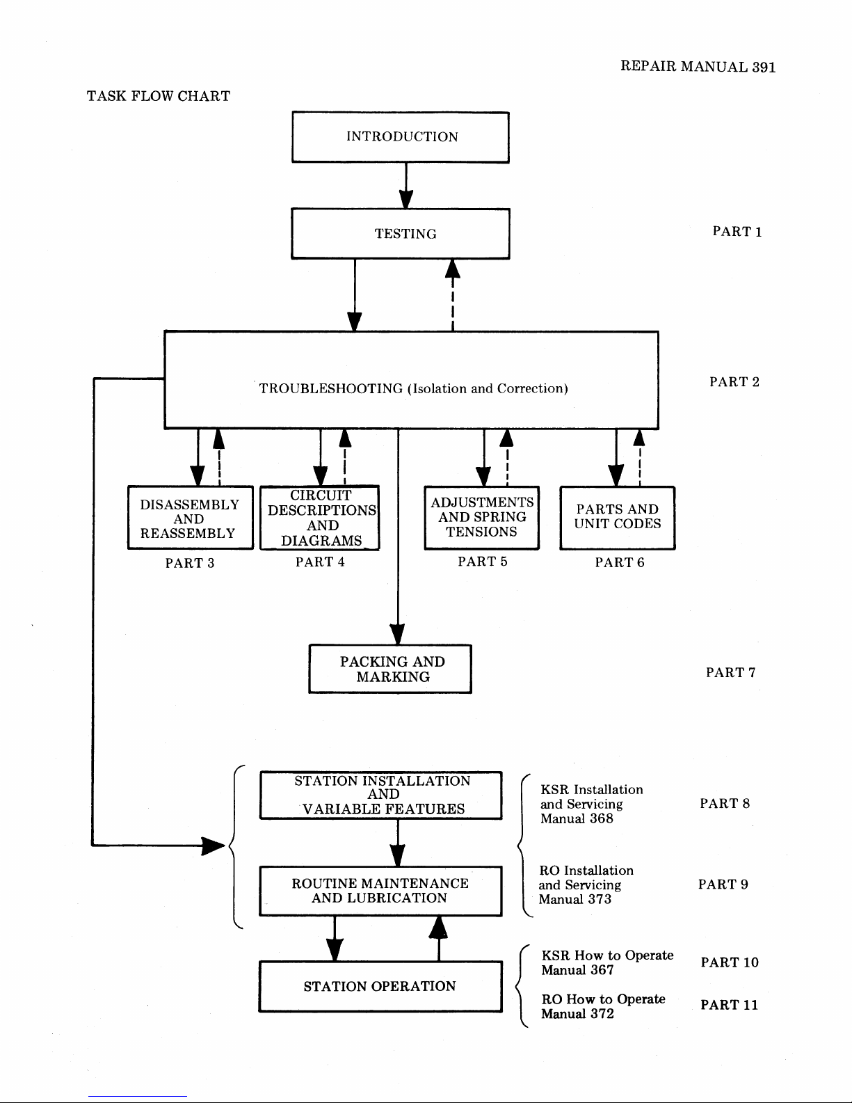
task
flow
chart
servicing activities
Spare
units
and
and
parts
on
the
for
Service personnel should
before
attempting
Corporation
on
43
Teleprinters.
service
Technical Training Center,
the
next
page illustrates
associated
manual
repair are available
be
properly
or
repair
trained
of
the
312-982-3940,
parts.
from
and
have access
43
Teleprinter.
the
intended
Teletype
Contact
for
courses available
repair
Corporation.
to
these spares
Teletype
or

The
43
TELEPRINTER
REP
AIR
MANUAL
PART
PART 9
PART
PART
PART
PART
PART
PART
PART
TABLE
1
2
3
4
5
6
7
TESTING
TROUBLESHOOTING
DISASSEMBL
CIRCUIT DESCRIPTION AND DIAGRAMS
ADJUSTMENTS
PARTS
PACKING
OF
CONTENTS
Y AND REASSEMBLY
AND SPRING TENSIONS
AND UNIT CODES
AND MARKING
SUPPLEMENTAL MANUALS INCLUDED
8
KSR INSTALLATION AND
ROUTINE
SERVICING MANUAL
RO INSTALLATION AND ROUTINE SERVICING MANUAL
368
373
Issue 3
Issue 2
PART
PART
10
11
KSR HOW
RO HOW
TO
TO
OPERATE
OPERATE
MANUAL
MANUAL
367
372
Issue 2
Issue 2
REPAIR
MANUAL
391
TASK
FLOW
CHART
+
DISASSEMBL Y
REASSEMBLY
" !
AND
PART 3
INTRODUCTION
"
TESTING
+
I
I
I
"
TROUBLESHOOTING (Isolation and Correction)
+
" !
CIRCUIT
DESCRIPTIONS
AND
DIAGRAMS
PART 4
ADJUSTMENTS
AND SPRING
TENSIONS
l
" :
PART 5
~
I
" I
PARTS AND
UNIT CODES
PART
6
PART
PART
1
2
......
~
PACKING
MARKING
r
ST ATION INSTALLATION
AND
VARIABLE
ROUTINE MAINTENANCE
AND LUBRICATION
,r
STATION
AND
FEATURES
"
.4
~
OPERATION
KSR Installation
and Servicing
Manual
RO Installation
and Servicing
Manual
KSR
How
Manual
RO
{
How
Manual
368
373
367
to
372
to
Operate
Operate
PART
PART 8
PART
PART
PART
7
9
10
11
PART 1-TESTING
MANUAL
391,1-1
GENERAL
1.
TEST
2.
KSR
3.
OFF-LINE
V ARIABLE
CHECKOUT
A.
B.
4.
RO
OFF-LINE
V ARIABLE
CHECKOUT
A.
B. Variable
1.
GENERAL
1.01
RO
Teleprinter.
1.02
nents
are
operate
ating
conditions.
1.03
not
provided in
is
found
and
is
used
this
in
CONTENTS PAGE
....................
EQUIPMENT
TESTING
TESTS
FEATURES
...................
Loopback
Variable Features
TESTING
TESTS
FEATURES
...................
Loopback
This
part
provides testing
and
procedures
The
information
determine
if
operating
for
extended
Endurance,
electrical
parameter
this
to
some
extent
to
isolate
part.
.............
.................
...............
Mode
............
Checkout
..................
...............
Mode
Features
properly
for
in
th~
terminal
periods
............
Checkout
the
this
and
under
environmental
testing
part.
This
type
in
Part
2,
and
correct
...
requirements
43
Basic
KSR
part
is
intended
and
its
compo-
will
continue
normal
oper-
extreme
information
of
information
Troubleshooting
troubles
indicated
12
12
12
15
15
20
20
20
and
to
to
or
is
(b) A questionable
teleprinter
1
2
repair.
(c) A questionable teleprinter, in service
received
3
3
properly
1.05
or
requires repair.
Following installation
ance calls
this
part
or
an
HTO
manual should
the
teleprinter
1.06
On
is operational.
trouble
verification
test
station
isolate
After
confined
1.07
(if available) should
the
trouble
correction
to
the
specific
The
checkout
table
form
in a specific sequence. A response is given
verify
the
test
condition
1.08
factory
1.09
step
performed
factory,
1.10
Always
given.
results
If
the
in
any
to
make sure
properly.
refer
to
Teleprinters
minal
perform
The
of
indicated
step
Data
locally developed
and
procedures
If
test
station
procedure
Note:
late
The
most
to
is
should
local
on-line
component
operates
from a customer,
at a location,
installation
be
performed
calls, a local
test
under
within
or
of a trouble,
area
that
routines
with
test
has
passed.
the
test
steps are based
installed
properly
or
routine
either
checkout
to
test
the
direction
be
performed
to
the
the
was failing.
are
presented
conditions
tests in
or
requires
is
operating
mainten-
the
testing
using
make
or a trouble
teleprinter.
test
may
arranged
the
on
all previous steps.
response is
of a test
that
the
If
the
procedure,
procedure
results
not
repeat
are
still unsatis-
obtained
has
Page 2-1, Troubleshooting.
with
TAUs
Unit
must
external
perform
remote, a copy
be
available
tests
specified
tests
for
or
be
testing
actual
at
the
in
these
with
no
associated
arrangements
On-Line Tests.
of
the
test
station.
this
part
teleprinters.
in
the
or
in
the
sure
of
a
to
be
in
to
order
satis-
the
been
Ter-
with
testing
simu-
1.04
The
testing
should
normally
(a) A repaired
before
being
information
be
used
teleprinter
returned
is
placed in service.
provided herein
to
determine
operating
properly
to a customer
if:
or
--1.11
Before
the
remote
an
on-line
testing
vided with advance details
under
terminal
option
test,
such as,
(KSR
exceptions
telephone
or
RO) (friction
present,
test
station
about
speed,
can
be
must
the
number,
or
etc.
performed,
be
pro-
teleprinter
type
of
sprocket)
391,
1-2
1.12
Before proceeding
procedure,
(a) Is
grounded
teleprinter
check
and
(b) Are all cable
(c) Are
printer
with
the
following:
connected
polarized ac
connectors
paper
and
the
to
outlet?
fully seated?
ribbon
installed?
(d) Are
Page
to
2-1.
Manuals
any
option
(Part 8 or
exceptions
368
(KSR)
9)
present?
and
Procedures in Off-Line Tests are based
factory
exceptions
as
furnished
shown
options
are present,
in
the
KSR
being present.
the
test
response will
or
RO
Variable
Checkout.
1.13
index
head
All references
second delay,
two
character
indicates
the
to
to
spaces
next
columns
allow
the
to
the
character
are
right.
position
printed.
2.
TEST
EQUIPMENT
and
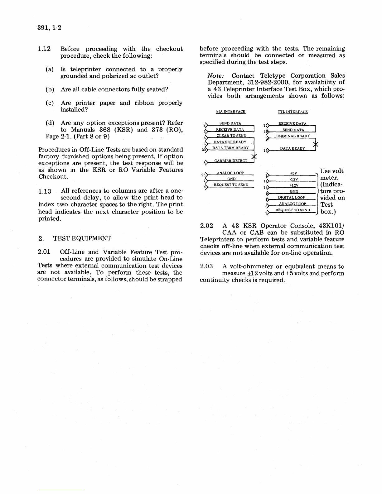
2.01 Off-Line
cedures are provided
Tests where
are
not
connector
external
available.
terminals, as follows, should
Variable
communication
To
perform
Feature
to
simulate On-Line
these
checkout
a properly
properly
373
(RO),
on
standard
If
option
Features
after
a one-
print
head
The
Test pro-
test
devices
tests,
be
strapped
Refer
be
to
print
to
be
the
before
proceeding
terminals should
specified
Note:
during
Contact
Department,
a
43
Teleprinter
vides
:S
5
6
25)
7)
4)
2.02
Teleprinters
checks off-line
devices are
2.03
both
EIA INTERFACE
SEND DATA
RECEIVE DATA
CLEAR TO SEND
DATA SET READY
DATA TERM READY
ANALOG LOOP
GND
REQUEST TO SEND
A
43
KSR
CAA
or
to
not
A
volt-ohmmeter
arrangements
perform
when
available
measure ±12 volts
continuity
checks is required.
with
the
tests.
be
connected
the
test
steps.
Teletype
312-982-2000,
Interface
~~
.:
V
11)
1~
~
1)
3)
6)
Test
TTL
INTERFACE
RECEIVE
SEND DATA
TERMINAL READY
DATA READY
DIGITAL LOOP
ANALOG LOOP
REQUEST TO SEND
Operator
CAB
can
be
tests
external
for
on-line
or
equivalent means
and
+5 volts
The
remaining
or
measured as
Corporation
for
availability
Box, which pro-
shown
as follows:
DAT,&
f
+5V
·12V
+12V
GND
Console,
substituted
and
variable
communication
Use
meter.
(Indicators
vided
Test
box.)
43K101/
in
feature
operation.
and
perform
Sales
of
volt
pro-
on
RO
test
to
3.
KSR TESTING
OFF-LINE TESTS
TABLE A
OFF-LINE TEST PROCEDURES
MANUAL
391,1-3
TEST
Power
On/Off
Printer
Option
431.a.
432.a.
STEP
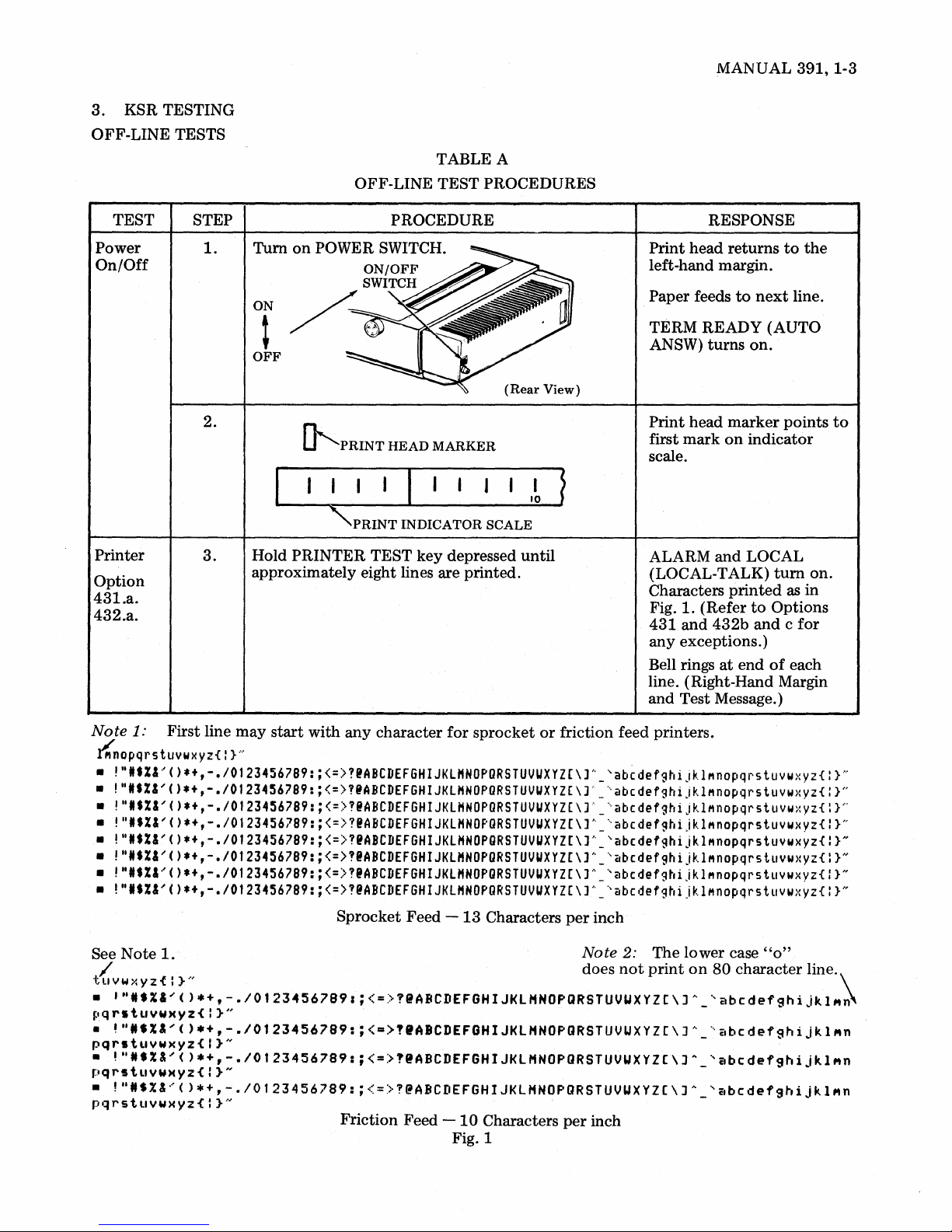
1.
2.
3.
PROCEDURE
ON
t
OFF
(Rear
~PRINT
HEAD
MARKER
I 10
"PRINT
Hold
PRINTER
approximately eight lines are printed.
INDICATOR
TEST
key
SCALE
depressed
View)
until
~
RESPONSE
Print
head returns
left-hand margin.
Paper feeds
TERM
ANSW)
Print
first
mark
scale.
ALARM
(LOCAL-TALK)
Characters
Fig.
1.
431
and
any
exceptions.)
Bell rings
line. (Right-Hand Margin
and
Test Message.)
to
READY (AUTO
turns
head
marker
on
and
printed
(Refer
432b
at
end
to
next
line.
on.
points
indicator
LOCAL
turn
as
to
Options
and c for
of
each
the
on.
in
to
Note
1:
First line
~nopqrstuvwxyZ{:
• ".tX&/().+,-.IOt23456789:;<=>!@ABCDEF6HIJKLMNOPDRSTUVUXYZ(\]h_'abcdefghiJklMnopqrstuvwxyz{
• ".tX&'()*+,-.IOt23456789:;<=>?@ABCDEFGHIJKlHNOPURSTUVUXYZ[\)'_'abcdefghiJklMnopqrstuvwxyz{
• ".tX&'()*+,-.IOt23456789:;<=>!@ABCDEF6HIJKLHNOPDRSTUVUXYZ[\]'_'abcdefghijklMnopqrstuvwxyz{ }P
• "'$X&'().+,-.I0123456789:;<=>?@ABCDEF6HIJKLHNOPDRSTUVUXYZ(\]h_'abcdefghijklMnopqrstuvwxyz{
• ".tX&'().+,-.IOt23456789:;<=>?@ABCDEF6HIJKLHNOPGRSTUVUXYZ[\]h_'abcdefghijklMnopqrstuywxyz{
• "'$X&'()*+,-.IOt23456789:;<=>?@ABCDEF6HIJKLMNOPGRSTUVUXYZ[\]h_'abcdefghijklMnopqrstuvwxyz{
• "ItX&'().+,-.IOt23456789:;<=>?@ABCDEF6HIJKlMNOPGRSTUVUXYZ[\]A_'abcdefghijklMnopqrstuvwxyz{
• "'$%&'().+,-.IOt23456789:;<=>?@ABCDEF6HIJKLMNOPDRSTUVUXYZ[\]h_'abcdefghijklMnopqrstuvwxyz{
Note
See
/ does
"tllVW>:YZ{:}"
•
'"I.X&'().+,-./01234567891;<=>?@ABCDEFGHIJKlHNOPQRSTUVUXYZC\J~_'abcdefghiJkl"~
pqrstuyw)(yz{I}"
•
~"I.X"().+,-.I0123456789:;<=>"ABCDEFGHIJKlHNOPQRSTUVUXYZC\]h_'abcdefghiJkl"n
pqrstuywxyz{!}"
•
!"N.X&'()*+,-./0123456789:;<=)?IABCDEFGHIJKlHNOPQRSTUVUXYZC\JA_'abcdefghijkl"n
pqrstllYW)(Yz{:}"
•
!"N.%&~()*+,-./Ot23456789:;<=)?@ABCDEFGHIJKlHNOpaRSTUVUXYZ(\JA_'~bcdefghijkl"n
pqrstllYWXYz{:}-"'
1.
may
}
....
start
with
any
character
Sprocket Feed -
Friction Feed
for
13
-10
Fig. 1
sprocket
Characters
Characters
or
friction feed printers.
per
inch
Note
2:
The lower case
not
print
per
inch
on
80
character line.
}N
}H
}H
}H
}N
}N
}N
"0"
\
391,
1-4
KSR OFF-LINE TEST (Cont)
TABLE A (Cont)
OFF-LINE TEST PROCEDURES
TEST
Printer
(Cont)
Operator
Console
STEP
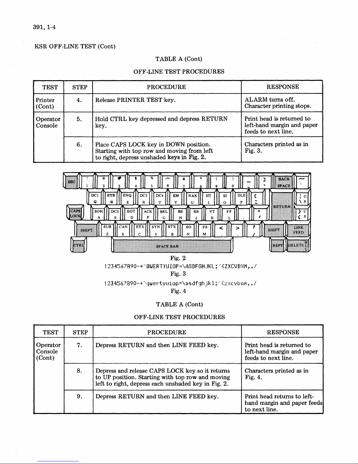
4.
5.
6.
PROCEDURE
Release
Hold CTRL
PRINTER
key
depressed
TEST key.
key.
Place CAPS LOCK
Starting with
to
right, depress unshaded keys
key
in
top
row and moving from
and
depress RETURN
DOWN position.
left
in
Fig. 2.
RESPONSE
ALARM
turns
off.
Character printing stops.
Print head is
left-hand margin
to
feeds
Characters
next
printed
returned
and
line.
as
to
paper
in
Fig. 3.
TEST STEP
Operator
Console
(Cont)
7.
8.
9.
Fig. 2
1234567890-+'OWERTYUIOP=\ASDFGHJKL;~{ZXCVBNM,.1
Fig. 3
'1
23456?890-+
···qwer'tyuiop:=\asdf'3hjkl;··
{z;.:cvbnf"l,
.1
Fig. 4
TABLE A (Cont)
OFF-LINE TEST PROCEDURES
RESPONSE
head
is
Depress RETURN
PROCEDURE
and
then
LINE
FEED
key.
Print
left-hand margin
feeds
to
next
Depress
to
left
Depress RETURN and
and
release CAPS LOCK
UP position. Starting with
to
right, depress each unshaded
then
top
LINE
key
row
key
FEED
so
it
returns
and
moving
in Fig. 2.
key.
Characters
printed
Fig. 4.
Print head returns
hand
margin
to
next
line.
returned
and
line.
as
to
and
paper
to
paper
in
left-
feeds
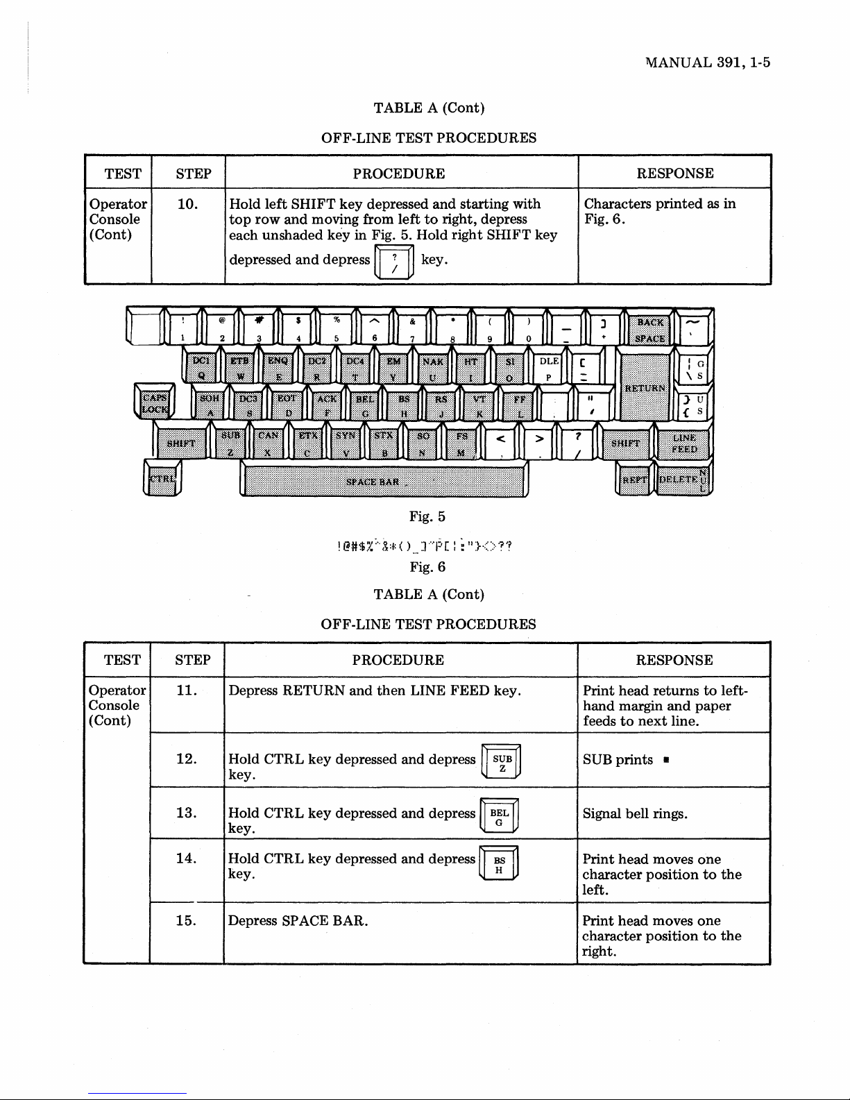
TABLE A (Cont)
OFF-LINE TEST PROCEDURES
lV1ANUAL
391,
1-5
TEST STEP
Operator
Console
(Cont)
10.
PROCEDURE
Hold left SHIFT key depressed and starting with
top
row and moving from left
each unshaded
depressed
key in Fig. 5. Hold right SHIFT key
and
depress
!
@#$:.~
rn
;"
(~:t:
Fig. 5
( )
... ] ....
Fig. 6
to
right, depress
key.
1:·
[ : :
II
}<>
'?'f
RESPONSE
Characters printed
Fig.
6.
as
in
TEST STEP
Operator
Console
(Cont)
II.
12.
13.
14.
15.
TABLE A (Cont)
OFF-LINE TEST PROCEDURES
PROCEDURE
Depress RETURN and then LINE FEED key.
Hold
CTRL
key.
Hold
CTRL
key.
Hold
CTRL
key. H
Depress SPACE BAR.
key
key
key
depressed
depressed
depressed
and
and
and
depress
depress
depress
~
S~B
~
"ilL
rn
~
~
RESPONSE
head returns
Print
hand margin and paper
feeds
to
next
SUB prints 8
Signal bell rings.
Print head moves
character position
left.
Print head moves
character position
right.
line.
to
one
to
one
to
left-
the
the

391,1-6
KSR OFF-LINE TESTS (Cont)
TABLE A (Cont)
TEST
Operator
Console
(Cont)
Cover
Inter-
lock
Right
Margin
and
Signal
Bell
STEP
16.
17.
18.
19.
20.
21.
OFF-LINE TEST
PROCEDURE
Depress BACK SPACE key.
Depress LINE FEED key.
Depress
Depress TERM READY
Raise cover.
Close cover.
Depress RETURN and
Space
(See
Space
and
print
1.13)
print
hold
head
head
REPT and
(AUTO ANSW) key.
the
to
column
to
column
PROCEDURES
rn
LINE
125
73
keys.
FEED
(sprocket feed).
(friction feed).
key.
RESPONSE
head
is
printed
is
reached.
turns
to
next
moves
Print
character position
left.
Paper feeds
The k
of
line
, Signal bell rings
line.
TERM READY
ANSW) goes off. LOCAL
(LOCAL-TALK)
ALARM
ALARM goes off.
Print head returns
hand margin
feeds
to
and
line.
one
to
next
until
at
end
(AUTO
and
on.
to
paper
line.
the
end
of
left-
Margin
Set
and
Clear
(Remem-
ber
Lower
Case)
22.
23.
24.
25.
Depress
Depress
Depress
Depress
Depress SPACE BAR nine times.
Depress
(ESCL lower case.)
~
""Ii'
~
key.
SPACE BAR six times.
SPACE BAR
ESC
and
ESC and
then
then
two
times.
~
c~
~
rn
L
key. (ESCx)
key.
Signal bell operates as
is
character b
printed.
Signal bell does
Print head moves six
ate.
character positions
right.
Signal bell operates
times.
Print head returns
left-hand margin and indi-
cates beginning
Print head moves
Column 10.
being
not
of
to
oper-
to
two
to
line.
the

TABLE A (Cont)
OFF-LINE
TEST
PROCEDURES
MANUAL
391,
1-7
TEST
Margin
Set
and
Clear
(Cont)
STEP
26.
27.
28.
29.
30.
3l.
PROCEDURE
Space
print
head
to
Column
Depress ESC and
Depress
Depress BACK SPACE key.
Space
Depress SPACE BAR.
Depress
Depress ESC
Depress SPACE
Depress ESC
RETURN
print
SPACE BAR.
head
and
and
then
~
D~2
key.
to
Column 50.
then
m key (ESC
BAR
four
then
~
EJ:
5l.
~
key. (ESCr)
times.
~
key
m
(ESCw).
)·
RESPONSE
Print
head
returns
margin
Signal bell rings.
Signal bell operates.
Print
5l.
Signal bell rings.
Print
Column
Print
Column
Print
hand
and
(Column
head
head
head
head
margin
paper
indicates
remains
5l.
moves
55.
returns
(Column
feeds
10).
to
to
to
to
left
Column
at
left-
10)
next
line.
Turn
off
before
If
connector
Loopback
proceeding
the
43
TEST
POWER switch
to
Teleprinter Interface
(TTL
or
STEP
32.
~---
32.a.
and
Step
32.
EIA). See instructions furnished
Place
teleprinter
or
32
b.
1------------------
EIA
INTERFACE -Connect
Term
Ready.
Turn
on
connect
Test
Teleprinter
the
Box
OFF-LINE
test
arrangement
is available,
TABLE A (Cont)
TEST
PROCEDURE
in
loopback
POWER switch.
shown
connect
with
mode:
Carrier
the
test
box.
PROCEDURES
Perform 32 a
Detect
test
on
to
box
Data
Page 1-2
to
to
the
teleprinter
1----------
Print
left-hand margin.
feeds
turns
EIA
INTERFACE
CONNECTOR
+
12
V will
pin 4 (Issue
GND will be
pin
7.
the
interface
RESPONSE
head is
to
on.
next
be
2A
returned
line.
present
connector
interface
to
Paper
DATA
present
Logic Card)
on
on
391,
1-8
KSR OFF-LINE TESTS (Cont)
TABLE A (Cont)
OFF-LINE TEST PROCEDURES
TEST
Loopback
(Cont)
----
Option
434.a.
STEP
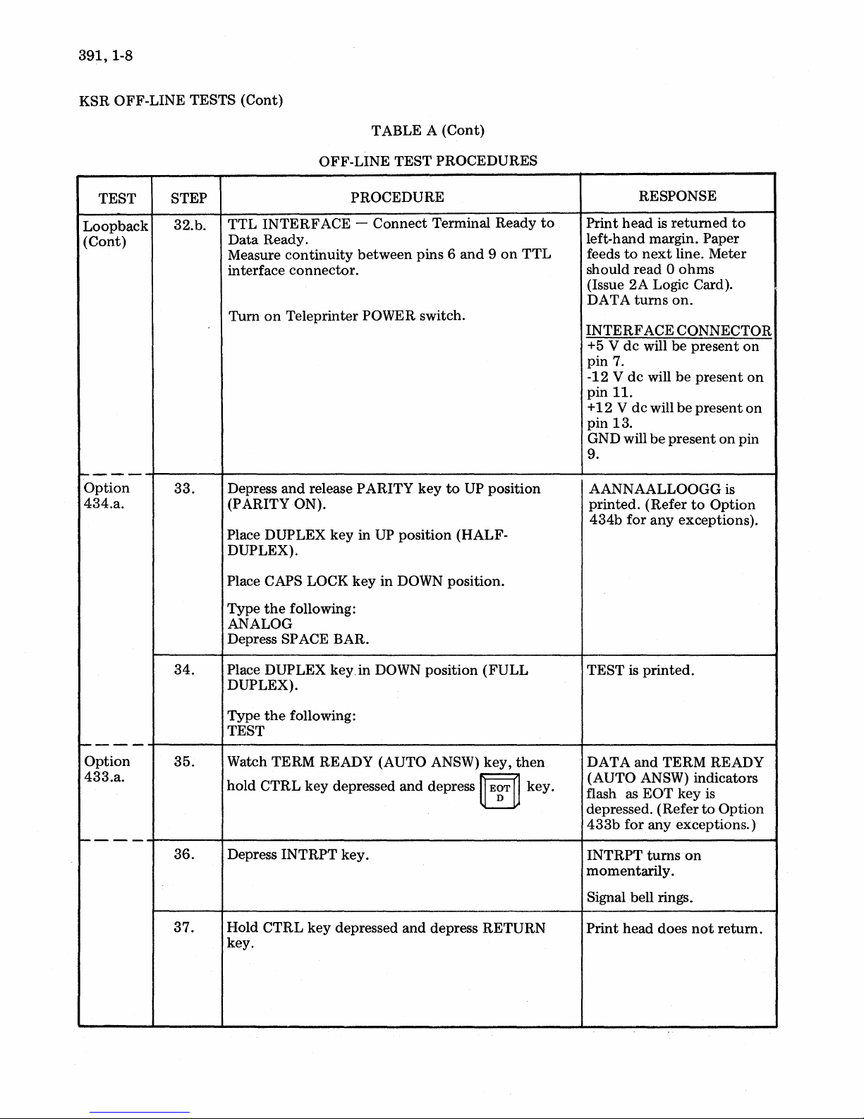
32.b.
33.
TTL
INTERFACE -
Data
Ready.
Measure
interface
Tum
Depress
(PARITY ON).
Place DUPLEX
DUPLEX).
Place CAPS LOCK
continuity
connector.
on
Teleprinter POWER switch.
and
release PARITY
key
PROCEDURE
Connect
between
in
UP
key
in DOWN position.
Terminal Ready
pins 6
key
position (HALF-
and 9 on
to
UP position
to
TTL
RESPONSE
Print
head
is
returned
left-hand margin. Paper
feeds
to
next
line. Meter
0
should read
(Issue
2A
DA T A
INTERFACE
+5 V
pin
-12
pin
+
pin
GND will
9.
AANNAALLOOGG is
printed.
434b
turns
dc
7.
V
dc
II.
12 V dc
13.
for
ohms
Logic Card).
on.
CONNECTOR
will be
will
(Refer
present
be
will
be
be
present
to
any
exceptions).
present
present
on
Option
to
on
on
on
pin
----
Option
433.a.
----
34.
35.
36.
37.
Type
the
following:
ANALOG
Depress SPACE BAR.
Place DUPLEX key.in DOWN position
DUPLEX).
Type
the
following:
TEST
Watch TERM READY (AUTO ANSW)
hold
CTRL
Depress
Hold
key.
INTRPT
CTRL
key
key
depressed
key.
depressed
and
depress
and
depress RETURN
(FULL
key,
then
~
E~T
~
key.
TEST is
DATA
(AUTO ANSW) indicators
flash as
depressed.
433b
INTRPT
momentarily.
Signal bell rings.
Print
printed.
and
TERM READY
EOT key
(Refer
for
any exceptions.)
turns
on
head
does
not
is
to
Option
return.
MANUAL
391,
1-9
TEST
Loopback
(Cont)
Option
435.a.
Option
435.a.
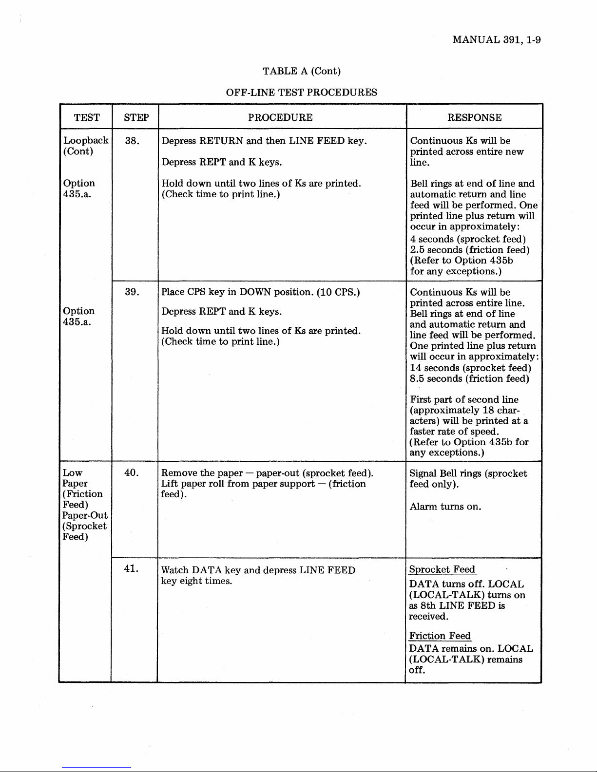
STEP
38.
39.
OFF-LINE TEST PROCEDURES
PROCEDURE
Depress RETURN and
REPT
and
Depress
down
time
CPS
until
key
Hold
(Check
Place
Depress REPT
down
Hold
(Check time
until
to
K keys.
two
to
print
line.)
in
DOWN position. (10 CPS.)
and
K keys.
two
print
line.)
TABLE A
then
LINE FEED key.
lines
of
lines
of
(Cont)
Ks
are printed.
Ks
are printed.
RESPONSE
Continuous
printed
Ks
will
across entire
be
new
line.
at
end
of
line
Bell rings
automatic
feed will
printed
occur
be
line plus
in approximately:
return
performed. One
return
and
and line
will
4 seconds (sprocket feed)
2.5 seconds (friction feed)
to
(Refer
for
Option
any exceptions.)
Continuous
printed
Bell rings
and
across
at
automatic
line feed will
One
printed
will occur
14
seconds (sprocket feed)
8.5
seconds (friction feed)
in
435b
Ks
will
be
entire
line.
end
of
line
return
be
line plus
and
performed.
return
approximately:
Low
Paper
(Friction
Feed)
Paper-Out
(Sprocket
Feed)
40.
41.
the
Remove
paper
Lift paper roll from
feed).
Watch DATA key
key eight times.
- paper-out (sprocket feed).
paper
support
and
depress LINE
- (friction
FEED
part
of
First
second
(approximately
rate
to
be
of
speed.
Option
acters) will
faster
(Refer
any
exceptions.)
line
18
char-
printed
435b
at
for
Signal Bell rings (sprocket
feed only).
turns
Alarm
on.
S:Qrocket Feed
DATA
(LOCAL-TALK)
as
8th
turns
LINE
off. LOCAL
turns
on
FEED
is
received.
Friction Feed
on.
DATA remains
(LOCAL-TALK)
LOCAL
remains
off.
a
391,1-10
KSR
OFF-LINE
TESTS
(Cont)
TEST
Low
Paper
(Friction
Feed)
Paper-Out
(Sprocket
Feed)
(Cont)
Loopback
Clear
Analog
Loop
STEP
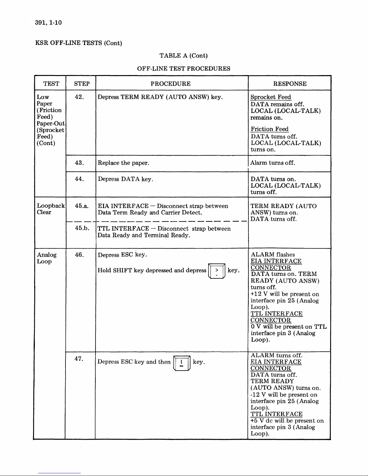
42.
43.
44.
45.a.
----
45.b.
46.
TABLE A
OFF-LINE
PROCEDURE
Depress
Replace
Depress
EIA
Data
TERM
the
DATA
INTERFACE -Disconnect
Term
READY (AUTO ANSW)
paper.
key.
Ready
and Carrier
TEST
------------------
TTL
INTERFACE -Disconnect
Data
Ready
I
Depress ESC
Hold
SHIFT
and
Terminal Ready.
-
key.
key
depressed
and
(Cont)
PROCEDURES
key.
strap
between
Detect.
strap
between
depress IT]
key.
RESPONSE
SQrocket
DATA
LOCAL (LOCAL-TALK)
remains
Friction
DA
LOCAL (LOCAL-TALK)
turns
Alarm
DATA
LOCAL (LOCAL-TALK)
turns
TERM
ANSW)
DATA
ALARM flashes
EIA
CONNECTOR
DATA
READY
turns
+12
interface
Loop).
TTL
CONNECTOR
o V will
interface
Loop).
Feed
remains
on.
Feed
T A
turns
off.
on.
turns
off.
turns
on.
off.
READY
turns
on.
turns
off.
INTERFACE
turns
on.
(AUTO
off.
V will
be
present
pin
25
INTERFACE
be
present
pin
3 (Analog
off.
(AUTO
TERM
ANSW)
(Analog
on
on
TTL
47.
Depress ESC
key
and
then
m
key.
ALARM
EIA
CONNECTOR
DATA
TERM
(AUTO
-12 V will
interface
Loop).
TTL
+5 V
interface
Loop).
turns
INTERFACE
turns
off.
READY
ANSW)
be
pin
25
INTERFACE
dc
will be
pin
3 (Analog
off.
turns
present
(Analog
present
on.
on
on
MANUAL
391,
1-11
TEST
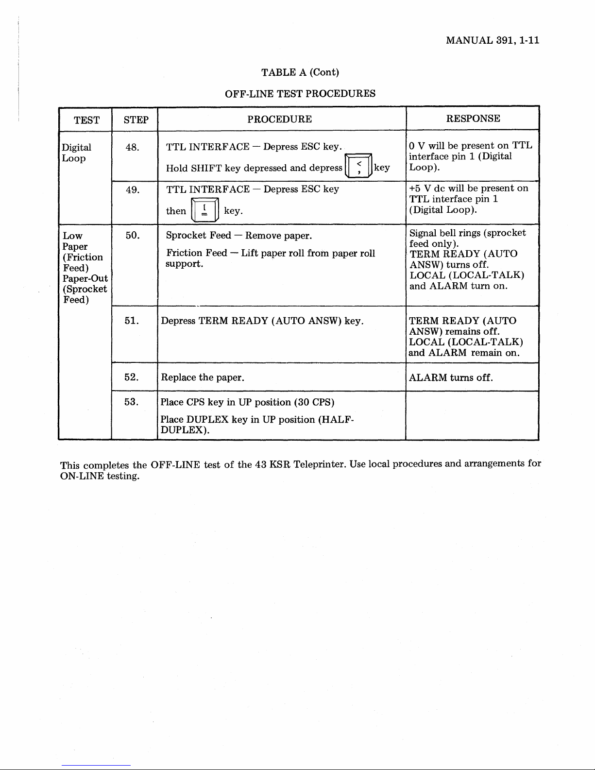
Digital 48.
Loop
Low
Paper
(Friction
Feed)
Paper-Out
(Sprocket
Feed)
STEP
49.
50.
51.
TABLE A
OFF-LINE
PROCEDURE
TTL
INTERFACE
Hold
SHIFT
TTL
INTERFACE
then
m key.
Sprocket
Friction
support.
Depress TERM READY (AUTO ANSW) key.
key
Feed
- Remove paper.
Feed -Lift
~
depressed
TEST
- Depress ESC key.
- Depress ESC key
paper
(Cont)
PROCEDURES
and
depress
roll from
paper
rn
roll
key
RESPONSE
o V will
interface pin 1 (Digital
Loop).
+5 V
TTL
(Digital
Signal bell rings
feed only).
TERM
ANSW)
LOCAL (LOCAL-TALK)
and
TERM
ANSW)
LOCAL (LOCAL-TALK)
and
be
present
dc
will
interface
Loop).
READY
turns
ALARM
READY
remains off.
ALARM
be
present
pin 1
(sprocket
(AUTO
off.
turn
(AUTO
remain
on
on.
TTL
on.
on
52.
53.
This
completes
ON-LINE testing.
the
Replace
Place CPS
Place DUPLEX
DUPLEX).
OFF-LINE
the
test
paper.
key
in
of
UP
key
the
position
in
UP
position
43
KSR
(30
CPS)
(HALF-
Teleprinter. Use local
ALARM
procedures
turns
off.
and
arrangements
for
391,1-12
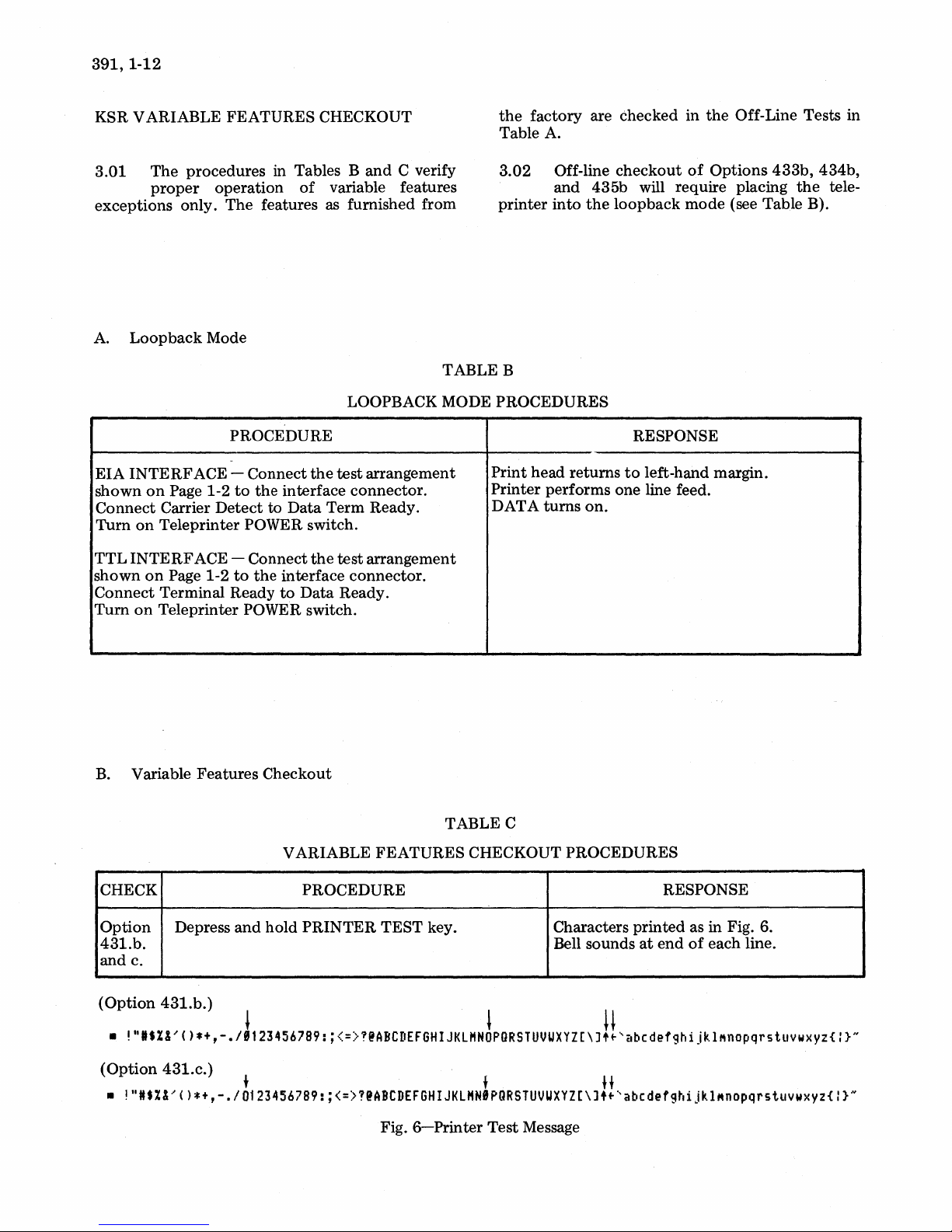
KSR VARIABLE FEATURES CHECKOUT
the
factory are checked in
Table A.
the
Off-Line Tests in
3.01
exceptions only.
A.
EIA
shown
Connect
Turn
TTL
shown
Connect
Tum
The
procedures in Tables
proper
Loopback
INTERF
on
on
INTERF
on
on
ACE - Connect
Page 1-2
Carrier
Teleprinter POWER switch.
ACE - Connect
Page 1-2
Terminal Ready
Teleprinter POWER switch.
operation
The
features as furnished from
Mode
PROCEDURE
to
the
Detect
to
to
the
Band
of
variable features
LOOPBACK MODE PROCEDURES
the
test
interface connector.
Data
Term Ready.
the
test
interface connector.
to
Data
Ready.
C verify
arrangement
arrangement
3.02
printer
TABLE B
Print head returns
Printer performs one line feed.
DATA
Off-line
and 435b will require placing
into
turns
checkout
the
loopback
on.
of
Options
mode
RESPONSE
to
left-hand margin.
(see Table B).
433b,
the
434b,
tele-
B.
Variable Features Checkout
V ARIABLE FEATURES CHECKOUT PROCEDURES
CHECK
Option
431.b.
and c.
(Option
•
!",.%&,()*+,-./J'234567B9:;<=>T@ABCDEFGHIJKLHN~PGRSTUVUXYZ[\J!!'abCdefghijkl~nOpqrstuvwXYZ{:}N
(Option
•
!"It%&'()*+,-./0123456789:;<=>?@ABCDEFGHIJKLHNIPQRSTUVUXYZ[\J
Depress
431.b.)
431.c.)
and
+ f H
PROCEDURE
hold
PRINTER
TABLE C
TEST key.
Fig.
6-Printer
Test
RESPONSE
Characters printed as in Fig. 6.
at
end
Bell sounds
Message
••
'abcdefghijkl~nopqrstuvwxY2{:}N
of
each line.
MANUAL
391,
1-13
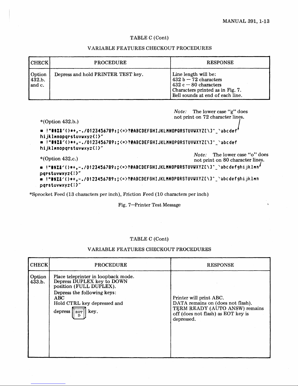
CHECK
Option
432.b.
andc.
*(Option
•
Depress
!"'.ZI~C)*+,-.I0123456789:;<=>!'ABCDEFGHIJKLHNOPQRSTUVUXYZ[\]A_
and
432.b.)
hijkl"nopqrstuvwxyz{I}N
•
!"'.ZI'C)*+,-.I0123456789:;<=>!@ABCDEFGHIJKLHNOPQRSTUVUXYZ[\]~_'abedef
hijkl"nopqrstuvwxyz{l}"
*(Option
•
!"'.ZI'C)*+,-.I0123456789:;<=>!@ABCDEFGHIJKLHNOPORSTUVUXYZ[\]A_'abcdefghijklMn
432.c.)
pqrstuvwxyz{I}N
•
!"'.Z&'C)*+,-.I0123456789:;<=>!@ABCDEFGHIJKLHNOPORSTUVUXYZ[\]h_'abcdefghijklMn
pqrstuvwxyz{l}"
VARIABLE
PROCEDURE
hold
PRINTER
TABLE C
FEATURES
TEST
key.
(Cont)
CHECKOUT PROCEDURES
RESPONSE
Line length will
432
b -
72
432
c -
80
Characters
Bell sounds
Note:
not
The
print
be:
characters
characters
printed
at
end
lower
on
72
Note:
not
print
as in Fig. 7.
of
each line.
case
"g"
character
'abedef
The
lower
on
80
does
lines.
/
case
character
"0"
does
lines.
'
*Sprocket
CHECK PROCEDURE
Option
433.b.
Feed
(13
characters
VARIABLE FEATURES CHECKOUT PROCEDURES
Place
teleprinter
Depress DUPLEX
position
Depress
ABC
Hold CTRL
depress
(FULL
the
ij
EgT
DUPLEX).
following keys:
key
~
key.
per
inch), Friction Feed (10 characters
in
loopback
key
to
depressed
Fig.
mode.
DOWN
and
7-Printer
TABLE
Test
Message
C (Cont)
per
inch)
will
Printer
DATA remains
TFiRM
off
(does
depressed.
print
READY (AUTO ANSW) remains
not
flash) as
RESPONSE
ABC.
on
(does
not
EOT
flash).
key
is
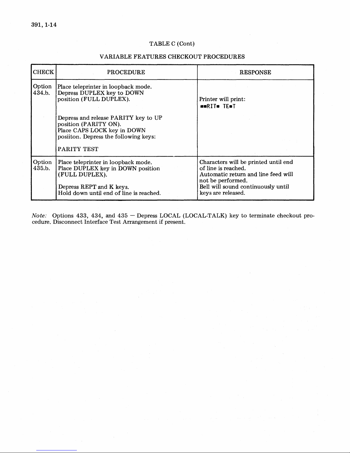
391,1-14
CHECK
Option
434.b.
Option
435.b.
VARIABLE
Place
teleprinter
Depress
position
Depress
position
Place CAPS LOCK
posiiton.
PARITY
Place
Place
(FULL
Depress
Hold
DUPLEX
(FULL
and
(PARITY
Depress
TEST
teleprinter
DUPLEX
DUPLEX).
REPT
down
in
DUPLEX).
release
in
key in DOWN
and
until
end
FEATURES
PROCEDURE
loopback
key
to
PARITY
ON).
key
the
following keys:
loopback
K keys.
of
mode.
DOWN
key
in
DOWN
mode.
line is reached.
TABLE C
to
UP
position
(Cont)
CHECKOUT
PROCEDURES
Printer
••
Characters
of
Automatic
not
Bell will
keys
will
print:
Rrr.
TE.T
will be
line is reached.
return
be
performed.
sound
are released.
RESPONSE
printed
and
continuously
until
line feed will
end
until
Note:
cedure.
Options
Disconnect
433,
434,
Interface
and
Test
435
- Depress LOCAL (LOCAL-TALK)
Arrangement
if
present.
key
to
terminate
checkout
pro-
4. RO TESTING
OFF-LINE TESTS
(Cont)
OFF-LINE
TABLED
TEST
PROCEDURES
MANUAL
391,
1-15
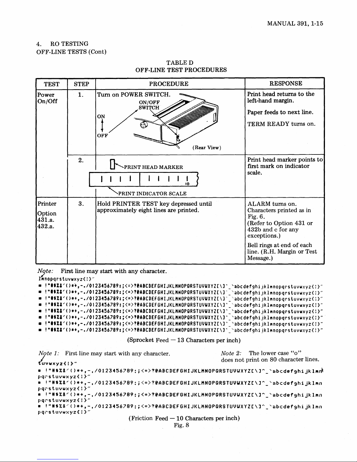
TEST
Power
On/Off
Printer
Option
431.a.
432.a.
STEP PROCEDURE
1.
Turn
on
POWER SWITCH.
2.
3.
~PRINT
"'PRINT
Hold
PRINTER
approximately
HEAD
MARKER
INDICATOR
TEST
SCALE
key
depressed
eight lines are printed.
(Rear
until
View)
RESPONSE
Print
head
returns
left-hand margin.
Paper feeds
TERM READY
Print
first
mark
to
head
'marker points
on
next
turns
indicator
scale.
ALARM
Characters
Fig.
(Refer
432b
6.
to
and c
turns
printed
Option
for
on.
any
exceptions. )
Bell rings
at
end
of
line. (R.H. Margin
Message.)
to
line.
as
431
each
or
the
on.
to
in
or
Test
Note:
l{nopqrs
•
•
•
•
• !"
•
•
•
Note
Iu
•
~lqj"stllYWXYZ{:
•
pqi"stllYwxyz{:
•
pqr'stllYwxyz{:
•
~Iqr'stllvwxyz{:
First line
may
start
with
any
character.
tuvwxyz{ : }..,
!"'.ZI'().~,-.I0123456789:·<=>?IABCDEFGHIJKLHNOPORSTUVUXYZ(\]A_'abcdefghiJkl"nop~rstuvwxyz{
!"'.ZI'()*+,-.I01234~6789:
!"'.%I'()*+,-.I01234~6789:
!"'.ZI'()*+,-./0123456789:
••
ZI'()*+,-.I0123456789:
!"'.ZI'().+,-.I01234~6789:
!"ltZI'()*+,-.I0123456789:
!"I.ZI'()*+,-.I0123456789:
1:
First line
Y W)( Y z { I } N does
!"HS%&'()*+,-.I0123456789:;<=>?@ABCDEFGHIJKlHNOPQRSTUVUXYZC\J~_'abcdef9hijkl"~
}"
may
start
<=>"ABCDEFGHIJKlHNOPORSTUVUXYZ(\]~_'abcdefghijkl"nopqrstuvwxyz{
<=>?'ABCDEFGHIJKL"NOPORSTUVUXYZ(\]~_'abcdefghiJkl"nopqrstuvwxyz{
<=>"ABCDEFGHIJKlHNOPORSTUVUXYZ[\]A_'abcdefghiJkl"nopqrstuvwxyz{
<=>?IABCDEFGHIJKlHNOPORSTUVUXYZ(\]A_'abcdefghijkl"nopqrstuvwxyz{
<=>"ABCDEFGHIJKlHNOPORSTUVUXYZ(\]A_'abcdefghijkl"nopqrstuvwxyz{
<=)?IABCDEFGHIJKlHNOPORSTUVUXYZ(\]A_'abcdefghijkl"nopqrstuvwxyz{
<=>"ABCDEFGHIJKlHNOPORSTUVUXYZ(\]A_'abcdefghijklMnopqrstuvwxyz{
(Sprocket Feed
with any character. Note
-13
Characters
per
inch)
2:
not
The lower case
print
on
80 character
"0"
}N
}N
}N
}H
}N
}N
}N
}N
lines~
!"HS%&'()*+,-.I0123456789:;<=>?@ABCDEFGHIJKlHNOPQRSTUVWXYZC\JA_'abcdefghijkl"n
}"
!"HS%&'()*+,-.I0123456789:;<=>?@ABCDEFGHIJKlHNOPQRSTUVUXYZC\J~_'abcdef9hijkl"n
!"
H S % &.' ( ) * + , - • I 0 1 2 3 4 5 6 7 8 9 : ; < = > ? @
},
}
....
..
ABC
II
(Friction Feed -
E F G H I J K l H N 0 P Q R
10
Characters per inch)
STU
V U X Y Z [ \ J
.... _ .,
it
bed
e f 9 h i j
",
1 III n
Fig. 8
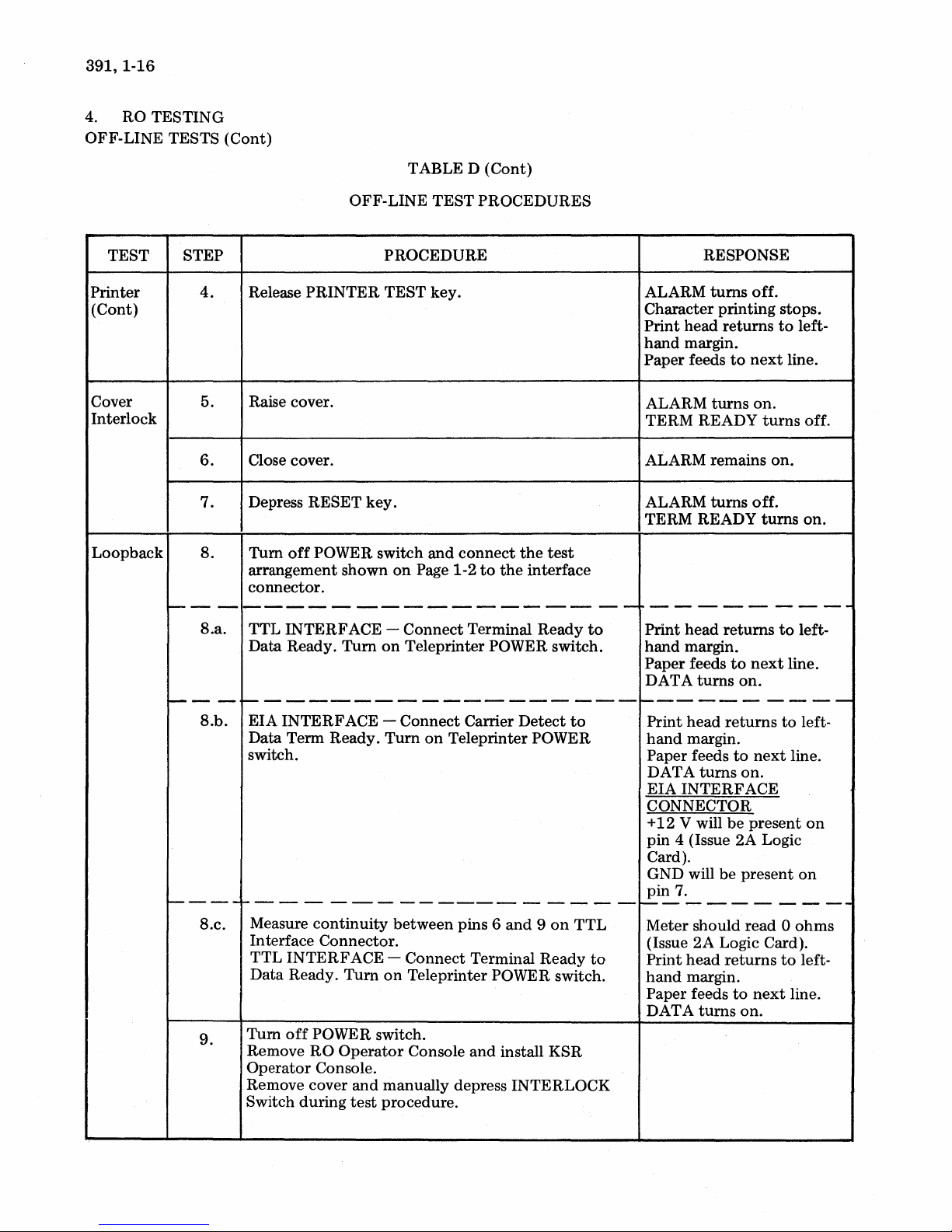
391, 1-16
RO TESTING
4.
OFF-LINE TESTS (Cont)
TABLE D (Cont)
TEST STEP
Printer
(Cont)
Cover
Interlock
Loopback
---
i---
1-----
4.
5.
6.
7.
S.
Release PRINTER TEST key.
Raise cover.
Close cover.
Depress RESET key.
Tum
off
POWER switch
arrangement shown
connector.
-----------------
S.a.
- -
S.b.
TTL INTERFACE - Connect Terminal Ready
Data Ready. Turn
~-----------------
EIA INTERFACE - Connect Carrier Detect
Data Term Ready.
switch.
1------------------
S.c.
9.
Measure
In terface Connector.
TTL INTERFACE Data Ready.
Tum
Remove
Operator Console.
Remove cover
Switch during
continuity
off
POWER switch.
RO
OFF-LINE
PROCEDURE
on
Turn
Turn
on
Operator
and
manually depress INTERLOCK
test
procedure.
TEST PROCEDURES
and
connect
on
Page 1-2
Teleprinter POWER switch.
on
between pins 6
Connect Terminal Ready
Teleprinter POWER switch.
Console
to
the
Teleprinter POWER
and 9 on
and
install KSR
the
test
interface
to
to
TTL
to
RESPONSE
ALARM
Character printing stops.
Print head returns
hand
Paper feeds
ALARM
TERM READY
ALARM remains on.
ALARM
TERM READY
10---------
--
Print head returns
hand margin.
Paper feeds
DATA
turns
margin.
turns
turns
turns
----------
Print head
hand
margin.
Paper feeds
DAT A
EIA INTERFACE
CONNECTOR
+
pin
Card).
GND will be present
pin
turns
12
V will
4 (Issue 2A Logic
7.
1-----------
Meter should read 0
(Issue 2A Logic Card).
head
Print
hand
margin.
Paper feeds
DAT A
turns
off.
to
next
on.
turns
off.
turns
to
next
on.
returns
to
next
on.
be
present
returns
to
next
on.
to
line.
to
line.
to
line.
to
line.
left-
off.
on.
left-
left-
on
on
ohms
left-

TABLE D (Cont)
MANUAL
391,
1-17
TEST STEP
Loopback
(Cont)
~---
10.
10.a.
II.
OFF-LINE
Tum
on
POWER switch.
f----------------
Depress
(P ARITY ON).
Place DUPLEX
DUPLEX).
Place CAPS LOCK
Type
ANALOG
Depress SPACE BAR.
and
the
following:
release PARITY
key
TEST
PROCEDURE
in
UP position (HALF-
key
in
PROCEDURES
key
to
DOWN position.
UP position
--
RESPONSE
TERM READY
[TTL
7.
V will
11.
V will be
13.
9.
turns
Interface
be
present
be
be
present
ANSW)
----------
W
+5 V will
pin
-12
pin
+
12
pin
GND will
pin
AANNAALLOOGG is
printed.
(AUTO
on.
Onl~
present
present
on
on
on
on
f-----
Option
433.a.
---
12.
13.
14.
Place DUPLEX
DUPLEX).
Type
the
TEST
Watch TERM READY (AUTO ANSW) key then'
hold
CTRL
Depress
Hold CTRL
key.
INTRPT
key
following:
key
depressed
key.
key
depressed
in
DOWN position (FULL
and
depress
and
depress RETURN
~
Eg"
~
key.
TEST
DATA
(AUTOANSW)
flash as
depressed.
(Refer
for
INTRPT
tarily. Signal bell rings.
Print
return.
is
printed.
and
EOT
to
Option
any
exceptions.)
turns
head does
TERM READY'
key
is
433b
on
momen-
not
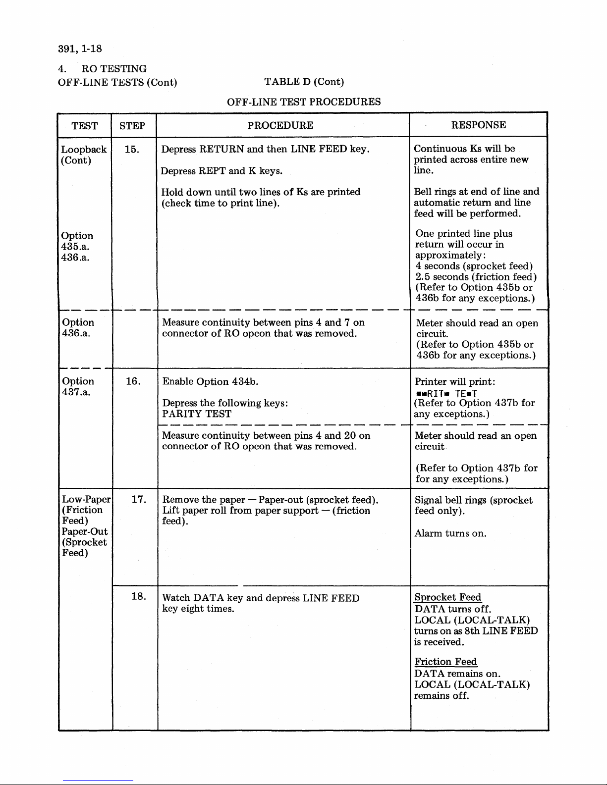
391,1-18
4. RO TESTING
OFF-LINE TESTS (Cont)
TABLE D (Cont)
TEST STEP
Loopback
(Cont)
Option
435.a.
436.a.
1-----
Option
436.a.
r---'-
1-----
Option
437.a.
15.
16.
OFF-LINE TEST
PROCEDURE
Depress RETURN and
Depress
Hold
(check time
REPT
down
and
until
to
print
K keys.
two
line).
then
lines
LINE
of
1----------------------
Measure
connector
Enable
Depress
PARITY TEST
continuity
of
RO
Option
the
434b.
following keys:
between pins 4
opcon
that
1--------------------
Measure
connector
continuity
of
RO
opcon
between pins 4 and
that
PROCEDURES
FEED
Ks
are printed
was removed.
was removed.
key.
and 7 on
20
on
RESPONSE
Continuous
printed
line.
Bell rings
automatic
feed will
One printed line plus
return
approximately:
4 seconds (sprocket feed)
2.5 seconds (friction feed)
(Refer
436b
ro-
-
-
--
Meter should read
circuit.
(Refer
436b
Printer will
..RI"T.
(Refer
any exceptions.)
---------
Meter should read
circuit.
Ks
will
across entire
at
end
of
return
be
will occur in
to
Option
for any exceptions.)
- -
to
Option
for any exceptions.)
TE.T
to
Option
and
performed.
435b
----
an
435b
print:
437b
an
be
new
line
line
open
and
or
--
open
or
for
-
Low-Paper
(Friction
Feed)
Paper-Out
(Sprocket
Feed)
17.
18.
Remove
Lift
feed).
Watch DATA key
key eight times.
the
paper
paper
roll from
- Paper-out (sprocket feed).
paper
support
and
depress LINE
- (friction
FEED
to
(Refer
for
Signal bell rings (sprocket
feed only).
Alarm
S:Qrocket Feed
DATA
LOCAL (LOCAL-TALK)
turns
is
received.
Friction Feed
DATA remains
LOCAL (LOCAL-TALK)
remains off.
Option
any exceptions.)
turns
turns
on
as
8th
437b
on.
off.
LINE FEED
on.
for
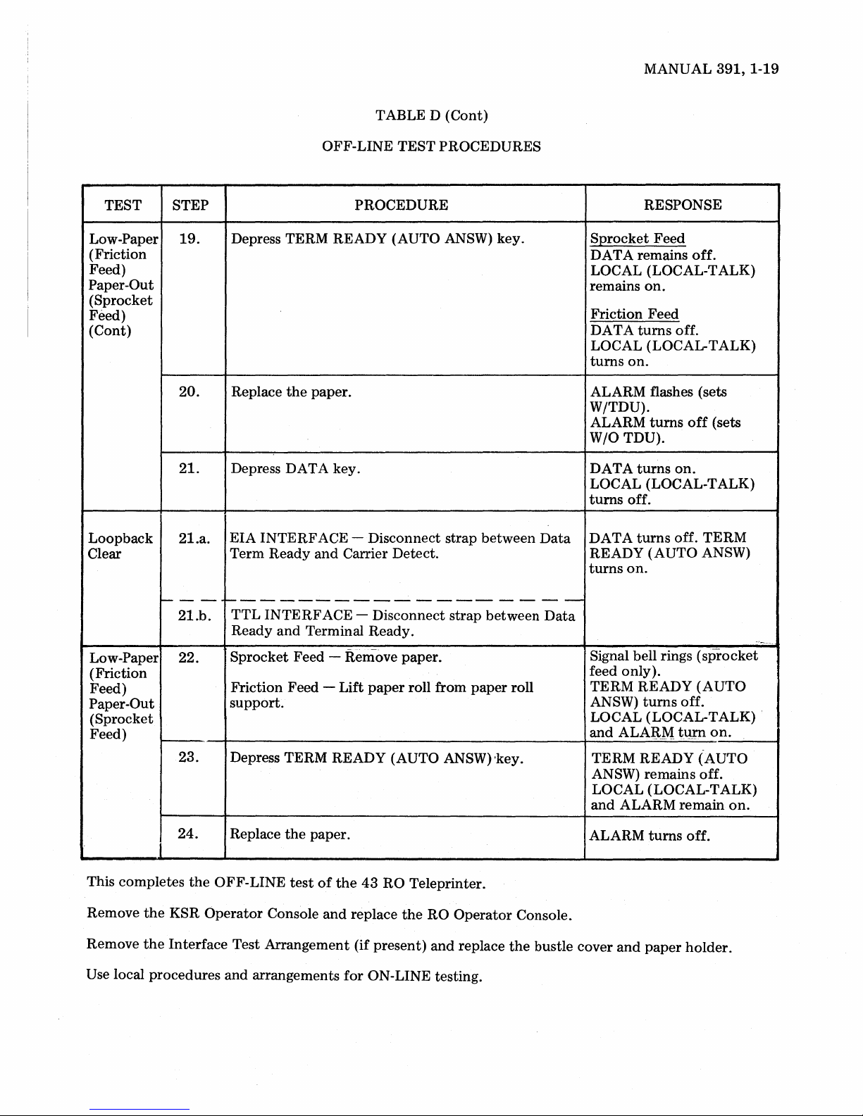
TABLE D (Cont)
MANUAL
391,1-19
TEST
Low-Paper
(Friction
Feed)
Paper-Out
(Sprocket
Feed)
(Cont)
Loopback
Clear
STEP
19.
20.
2l.
2l.a.
OFF-LINE
TEST
PROCEDURES
PROCEDURE
Depress TERM READY (AUTO ANSW) key.
Replace
the
paper.
Depress DATA key.
EIA
INTERFACE
Term
Ready
- Disconnect strap between
and
Carrier Detect.
Data
RESPONSE
SQrocket
DATA remains
Feed
off.
LOCAL (LOCAL-TALK)
remains
on.
Friction Feed
DA
T A
turns
off.
LOCAL (LOCAL-TALK)
turns
on.
ALARM flashes (sets
W/TDU).
ALARM
W/O
DATA
turns
TDU).
turns
off
on.
(sets
LOCAL (LOCAL-TALK)
turns
off.
DATA
turns
off.
TERM
READY (AUTO ANSW)
turns
on.
----
21.b.
Low-Paper 22.
~-----------------
TTL
INTERFACE
Ready
Sprocket
and
Terminal Ready.
Feed - Remove paper.
(Friction
Feed)
Paper-Out
Friction Feed -
support.
(Sprocket
Feed)
24.
This completes
the
the
KSR
Interface
Remove
Remove
23.
Depress TERM READY (AUTO ANSW) 'key.
the
the
OFF-LINE
Operator
Replace
Console
test
paper.
of
and
Test Arrangement (if present)
Use local procedures and arrangements
- Disconnect strap between
Lift
paper
roll from
the
43
RO Teleprinter.
replace
for
the
ON-LINE testing.
RO
Operator
and
replace
paper
Data
roll
Console.
the
bustle cover
Signal bell rings
(sprocket
feed only).
TERM READY
ANSW)
turns
(AUTO
off.
LOCAL (LOCAL-TALK) .
and
ALA:B.M
t\!J'Il
on.
TERM READY (AUTO
ANSW) remains off.
LOCAL (LOCAL-TALK)
and
ALARM
ALARM
and
turns
paper
remain
off.
holder.
on.
~

391,1-20
RO VARIABLE FEATURES CHECKOUT
4.01
only. The features
are checked in
A.
Remove RO
KSR Operator Console.
EIA
; shown
Connect Carrier Detect
Tum
TTL
'shown
'Connect Terminal Ready
Tum
The procedures in Table F verify
operation
Loopback Mode
INTERF
on
Page 1-2
on
Teleprinter POWER switch.
INTERF
on
Page 1-2
on
Teleprinter POWER switch.
of
variable feature exceptions
as
furnished from
the
off-line tests in Table D.
PROCEDURE
Operator
ACE - Connect
ACE - Connect
Console and install
the
to
the
interface connector. Printer performs one line feed.
to
Data Term Ready.
to
the
interface connector.
to
Data
LOOPBACK MODE PROCEDURES
test
the
test arrangement
Ready.
the
arrangement
proper
factory
TABLE E
4.02
teleprinter
the
Console (See Table E.)
Print head returns
DATA
Off-line
through
RO
turns
into
the
Operator
on.
checkout
437b
Console
RESPONSE
to
of
Options
will require placing
loopback
left-hand margin.
mode
with
and
a KSR
433b
the
replacing
Operator
B.
Variable Features
CHECK
Option
431.b.
andc.
(Option
•
!"It%'~()*+,-./112J456789:;<=>1'ABCDEFGHIJKl"NOPORSTUVUXYZ[\]+~'abcdet9hiJklMnopqrstuvwxyz{I}N
(Option 431.c.)
•
!lIlt%,~()*+,-./m23456789:;<=>?@ABCDEFGHIJKl"N!PORSTUVUXYZ[\]ti'abCdef9hijklMnOpQrstuYWXYZ{I}N
Depress
431. b. )
Checkout
TABLE F
FEATURES CHECKOUT PROCEDURES
TEST key.
and
VARIABLE
PROCEDURE RESPONSE
hold
PRINTER
~ ~
~
Fig.
9-Printer
Test Message
Characters
Bell sounds
~~
printed
at
end
as in Fig. 9.
of
each line.
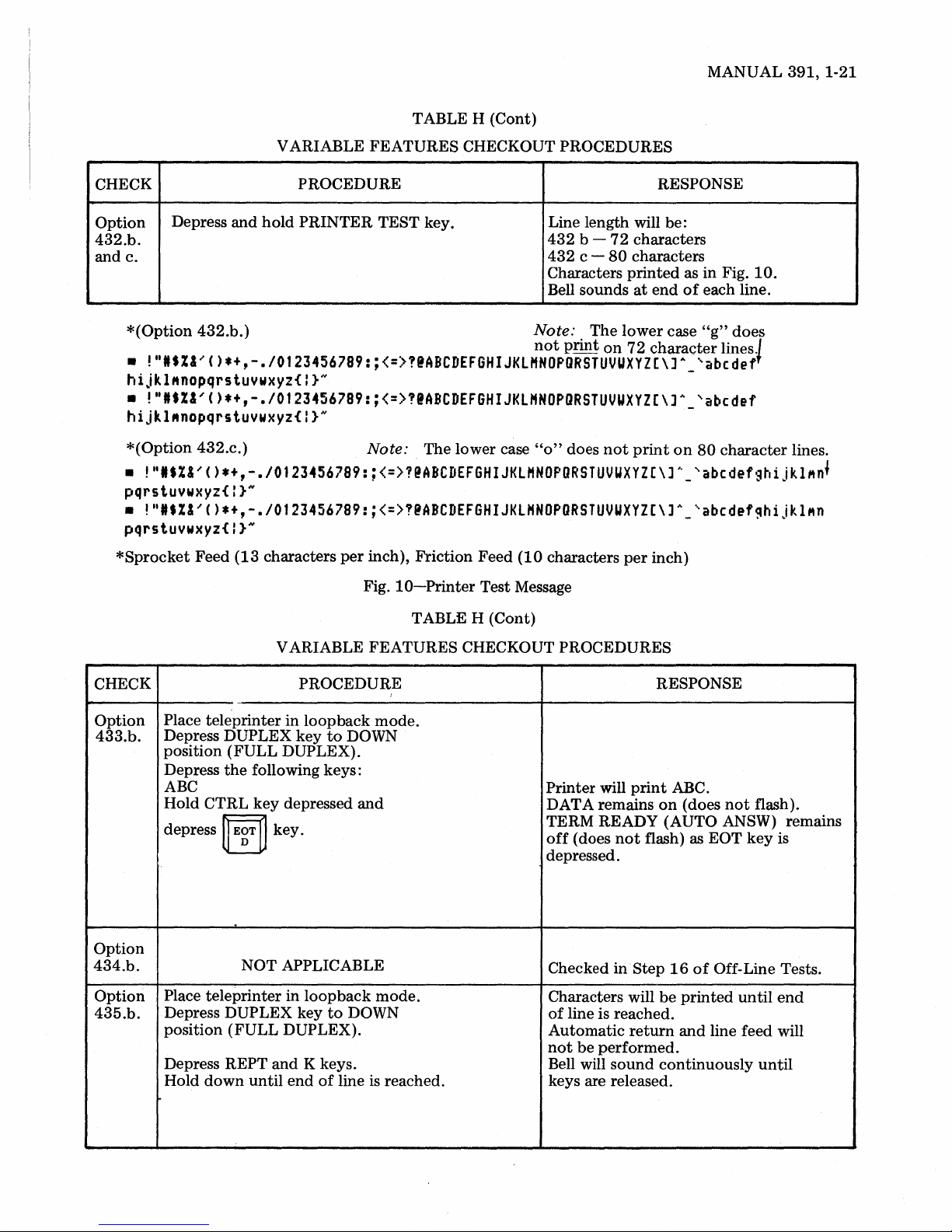
TABLE H (Cont)
MANUAL
391,1-21
CHECK
Option
432.b.
and
c.
*(Option
•
Depress
!"IS%I'()*+,-.I0123456789:;<=>?@ABCDEFGHIJKLHNOPORSTUVUXYZ[\)A
and
432.b.)
hijkl"nopqrstuywxyz{I}N
•
!ttIS%&'()*+,-.I01234S6789:;<=>?@ABCDEFGHIJKLHNOPORSTUVUXYZ[\]A_
hijkl"nopqrstuywxyz{I}N
*(Option
•
!"IS%I'()*+,-.I0123456789:;<=>1@ABCDEFGHIJKLHNOPORSTUVUXYZ[\]A_'abcdefghijkl"n
432.c.)
pqrstuywxyz{:}N
•
!"IS%I'()*+,-.I0123456789:;<=>!@ABCDEFGHIJKLHNOPORSTUVUXYZ[\]A_'abcdef~hijkl"n
pqrstuywxyz{:}N
*Sprocket
Feed
(13
V ARIABLE
PROCEDURE RESPONSE
hold
PRINTER
characters
FEATURES
TEST key.
CHECKOUT PROCEDURES
Note: The lower case
per
inch), Friction Feed
Fig.
10-Printer
Line length will be:
432
432
Characters
Bell sounds
Note: . The
not
"0"
(10
characters
Test Message
b c -
pnnt
does
72
characters
80
characters
printed
at
lower
on
72
not
print
per
end
character
inch)
as in Fig.
of
each line.
case
"g"
-'abcdef
'abcdef
on
80
10.
does
lines.J
character
lines .
f
V ARIABLE FEATURES CHECKOUT PROCEDURES
CHECK PROCEDURE
Option
433.b.
Option
434.b.
Option
435.b.
Place teleprinter in
Depress
position
Depress
ABC
Hold
depress
Place
Depress DUPLEX key
position
Depress REPT
Hold
DUPLEX key
(FULL
the
following keys:
CTRL
teleprinter
down
key
ij
EgT
NOT APPLICABLE
(FULL
until
loopback
DUPLEX).
depressed
~
key.
in
loopback
DUPLEX).
and
K keys.
end
to
to
of
line is reached.
I
mode.
DOWN
and
mode.
DOWN
TABLE H (Cont)
RESPONSE
Printer
DATA remains
TERM READY
off
depressed.
Checked
Characters will
of
Automatic
not
Bell will
keys are released.
will
print
(does
not
flash) as EOT
inStep
line is reached.
return
be
performed.
sound
ABC.
on
(does
not
flash).
(AUTO ANSW) remains
key
is
16
of
Off-Line Tests.
be
printed
and
continuously
until
end
line feed will
until

391,1-22
RO
VARIABLE FEATURES CHECKOUT (Cont)
CHECK
Option
436.b.
Option
437.b.
VARIABLE
PROCEDURE
Place teleprinter
Depress DUPLEX
in
loopback
key
to
DOWN
position (FULL DUPLEX).
Place CPS
key
in DOWN position
(10 CPS).
Depress REPT
Hold
down
and
until
K keys.
two
lines
printed.
Measure
1 7
Enable
Place
continuity
on
RO
Option
teleprinter
opcon
434b.
between
connector.
in
loopback
TABLE H
FEATURES
mode.
of
Ks
are
pins 4
and
mode.
(Cont)
CHECKOUT PROCEDURES
RESPONSE
Continuous Ks will
entire line.
at
return
end
and
Bell rings
matic
performed.
One printed line plus
occur
in
approximately:
14
seconds (sprocket feed)
8.5 seconds (friction feed)
part
of
First
imately
printed
second line (approx-
18
characters) will be
at
a faster
Meter should read
be
printed
of
line
and
line feed will
return
rate
of
speed.
0 ohms.
across
auto-
be
will
Place
CAPS
Depress
(FULL
DUPLEX).
Depress
PARITY
Measure
20
on
RG.
LOCK
DUPLEX key
the
following keys:
TEST
continuity
opcon
key in DOWN position.
to
DOWN position
between
pins 4
and
connector.
Note: Disconnect Interface Test arrangement,
Printer will
PARITY TEST.
Meter should read 0 ohms.
if
present. Replace RO
print:
operator
console.
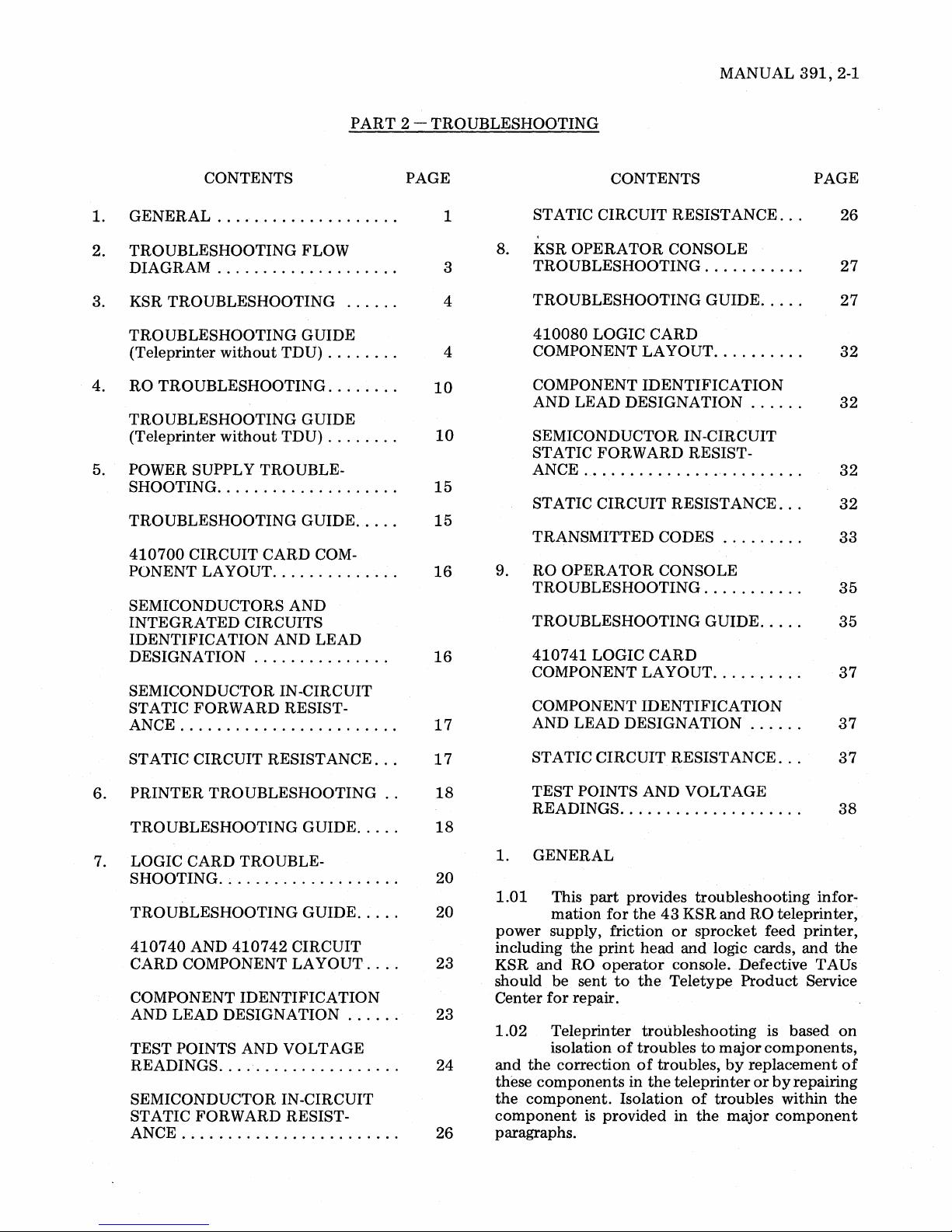
MANUAL
391,2-1
CONTENTS
1.
GENERAL
TROUBLESHOOTING FLOW
2.
DIAGRAM
TROUBLESHOOTING
KSR
3.
TROUBLESHOOTING GUIDE
(Teleprinter
4.
RO
TROUBLESHOOTING
TROUBLESHOOTING GUIDE
(Teleprinter
5.
POWER SUPPLY TROUBLE-
SHOOTING
TROUBLESHOOTING GUIDE
410700
PONENT
SEMICONDUCTORS AND
INTEGRATED
IDENTIFICATION AND LEAD
DESIGNATION
SEMICONDUCTOR IN-CIRCUIT
STATIC FORWARD RESISTANCE
....................
....................
without
without
....................
CIRCUIT CARD COM-
LAyOUT
........................
TDU)
TDU)
..............
CIRCUITS
...............
PART
......
........
........
........
.....
2 - TROUBLESHOOTING
PAGE
1
3
4
4
10
10
15
15
16
16
17
STATIC
8.
KSR
OPERATOR
TROUBLESHOOTING
TROUBLESHOOTING GUIDE
410080
COMPONENT
COMPONENT
AND LEAD DESIGNATION
SEMICONDUCTOR IN-CIRCUIT
STATIC
ANCE
ST ATIC CIRCUIT RESISTANCE
TRANSMITTED CODES
RO
9.
TROUBLESHOOTING
TROUBLESHOOTING
410741
COMPONENT
COMPONENT
AND LEAD DESIGNATION
.........................
OPERATOR
CONTENTS
CIRCUIT RESISTANCE
CONSOLE
...........
LOGIC
FORWARD
LOGIC
CARD
LAyOUT
IDENTIFICATION
CONSOLE
CARD
LAyOUT
IDENTIFICATION
..........
......
RESIST-
.........
...........
GUIDE
..........
......
.....
.....
...
...
PAGE
26
27
27
32
32
32
32
33
35
35
37
37
ST ATIC CIRCUIT RESISTANCE
PRINTER
6.
TROUBLESHOOTING GUIDE
LOGIC CARD TROUBLE-
7.
SHOOTING
TROUBLESHOOTING GUIDE
410740
CARD COMPONENT
COMPONENT IDENTIFICATION Center
AND LEAD
TEST
READINGS
SEMICONDUCTOR IN-CIRCUIT
STATIC FORWARD RESISTANCE
TROUBLESHOOTING
....................
AND
410742
DESIGNATION
POINTS AND VOLTAGE
....................
........................
CIRCUIT
LAYOUT
.....
.....
...
......
...
..
17
18
18
20
20
23
'
23
24
26
STATIC
TEST POINTS AND VOLTAGE
READINGS
GENERAL
1.
1.01
power
including
KSR
and
should be sent
for
1.02
and
the
these
components
the
component.
component
paragraphs.
CIRCUIT
....................
This
part
provides
mation
supply, friction
Teleprinter
isolation
correction
the
print
RO
operator
repair.
is
provided
for
the
head
to
the
troubleshooting
of
troubles
of
in
the
Isolation
RESISTANCE
43
or
and
console. Defective TAUs
Teletype
troubles,
teleprinter
in
troubleshooting
KSR
and
RO
sprocket
logic cards,
to
of
troubles
the
feed
Product
is based
major
components,
by
replacement
or
major
by
...
teleprinter,
within
component
37
38
infor-
printer,
and
the
Service
on
of
repairing
the
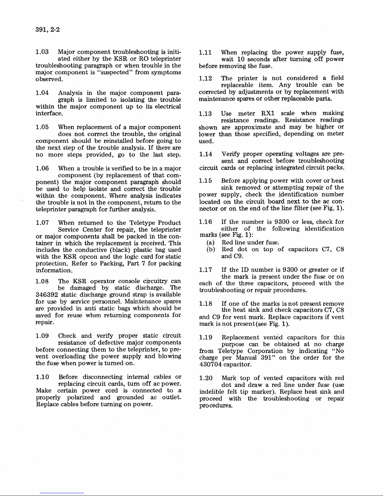
391,2-2
1.03
Major
ated
component
either
troubleshooting
major
component
observed.
1.04
Analysis in
graph is
within
the
major
interface.
1.05
component
the
no
1.06
When
next
more
When a
replacement
does
not
should
step
of
steps provided, go
component
ponent)
be
within
the
teleprinter
1.07
the
used
to
the
trouble
When
major
help
component.
is
not
paragraph
Service
or
major
tainer
includes
with
protection.
components
in
which
the
the
KSR
conductive
Refer
information.
1.08
346392
for
are provided
saved
The
KSR
be
damaged
static discharge
use
by
service personnel. Maintenance spares
for
reuse
in
repair.
by
paragraph
is
"suspected"
the
limited
component
correct
be
the
trouble
trouble
(by
component
isolate
in
the
for
returned
Center
the
replacement
opcon
to
operator
anti
static bags which should
when
troubleshooting
the
KSR
or
RO
teleprinter
or
when
trouble
from
symptoms
major
to
the
reinstalled
is verified
replacement
component
isolating
up
to
of a major
trouble,
before
analysis.
to
the
to
the
its electrical
component
the
original
going
If
there
last step.
be
in a major
of
that
paragraph should
and
correct
the
Where analysis indicates
component,
further
to
the
for repair,
shall be
return
analysis.
Teletype
the
packed
Product
teleprinter
in
the
is received. This
(black) plastic bag used
and
the
Packing,
logic card
Part 7 for
for
packing
console circuitry
by
static discharge.
ground
retur:r~ing
strap
is available
components
is initi-
in
the
para-
trouble
to
are
com-
trouble
to
the
con-
static
can
The
be
for
1.11
before
1.12
When replacing
wait
10
removing
The
printer
replaceable
corrected
maintenance
1.13
by
Use
adjustments
spares
meter
resistance readings. Resistance readings
shown
lower
are
approximate
than
those
used.
1.14
circuit cards
1.15
Verify
sent
and
or
Before applying
sink removed
power
located
nector
1.16
supply,
on
the
or
on
If
the
the
either
marks (see Fig.
(a) Red line
(b) Red
1.17
each
of
and
If
the
the
dot
C9.
the
mark
three
trOUbleshooting
1.18
and
mark
C9
is
If
the
for
not
one
heat
vent
present
the
seconds
the
fuse.
is
after
not
item.
or
or
other
RX1
and
specified,
proper
operating voltages are pre-
correct
replacing
before
integrated
power
or
attempting
check
circuit
number
of
end
the
the
board
of
the
is
9300
following
1):
under
fuse.
on
top
ID
number
is
is
present
capacitors,
or
repair procedures.
of
the
marks
sink
and
check
mark. Replace
(see Fig. 1).
power
supply
turning
off
fuse,
power
considered a field
Any
trouble
by
replacement
replaceable
scale
when
may
depending
be
can
parts.
making
higher
on
meter
with
troubleshooting
circuit
with
cover
repair
identification
next
to
the
packs.
or
heat
of
number
ac con-
line filter (see Fig. 1).
or
less,
check
identification
of
capacitors
9300
or
under
the
proceed
is
not
present
C7, C8
greater
fuse
with
remove
or
or
capacitors C7, C8
capacitors
if
vent
be
or
the
for
if
on
the
1.09
before
vent
the
1.10
Make certain
properly
Replace cables
Check
resistance
connecting
overloading
fuse
when
and
of
them
the
power
verify
defective
to
the
power
is
turned
proper
major
teleprinter,
supply
on.
Before disconnecting internal cables
replacing
polarized
circuit
power
before
cards,
cord is
and
grounded
turning
tum
on
static circuit
components
and
blowing
off
ac power.
connected
ac
power.
to
pre-
or
to
outlet.
1.19
from
charge
430704
1.20
a
indelible felt
proceed
Replacement
purpose can be
Teletype
per
Corporation
Manual
capacitor.
Mark
top
of
dot
and
draw a red
tip
marker). Replace
with
the
vented
capacitors
obtained
by
indicating
391"
on
the
vented
capacitors
line
under
troubleshooting
at
no
order
heat
or
for
this
charge
"No
for
the
with
red
fuse (use
sink
and
repair
procedures.
 Loading...