

Page 1
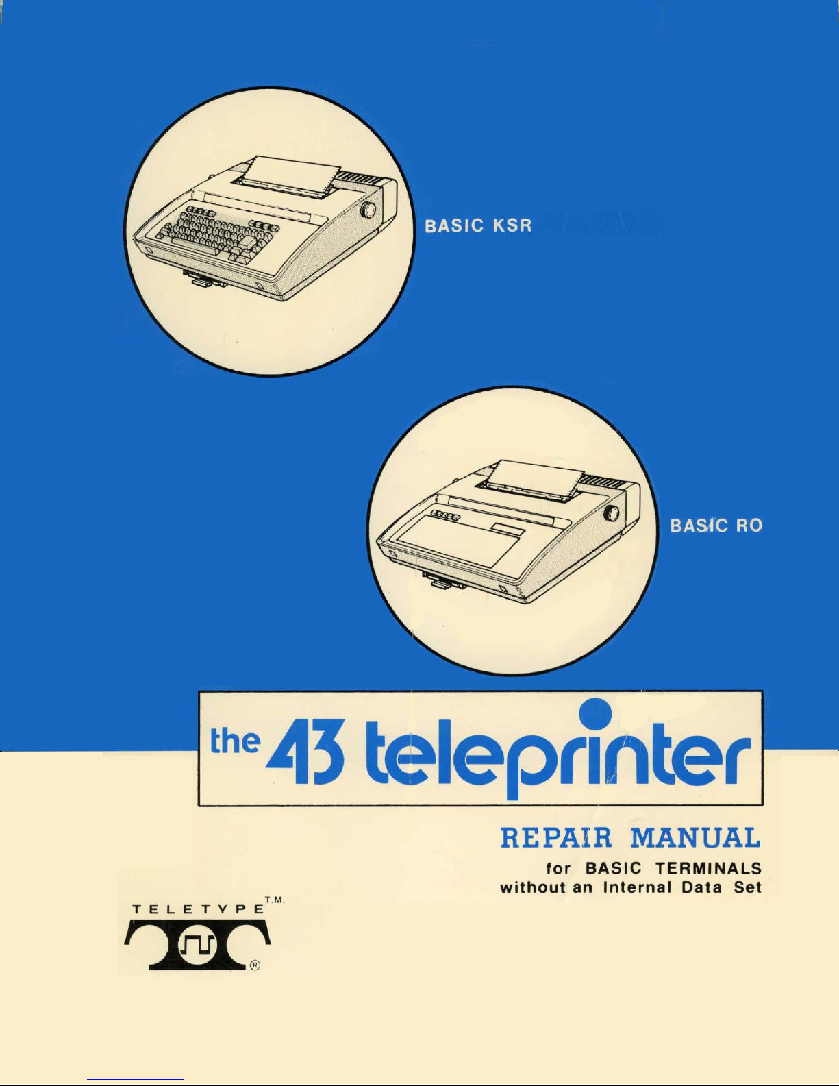
e
the
113
teleprinter
T.M
.
TELETYPE
,
InrI:'
REPAIR MANUAL
for
BASIC
TERMINALS
without
an
Internal
Data
Set
Page 2

©
1978
by
Teletype Corporation
All rights reserved
Printed
in
U.S.A.
Page 3
The
43
TELEPRINTER
REPAIR MANUAL
REP
AIR
MANUAL
391
Comments concerning
be
welcomed. This
Corporation. This
sheet
sheet
this manual.
content,
may
be removed
may
usability,
also be used
and
adequacy
and
mailed directly
for
ordering additional copies
of
this manual will
to
Teletype
of
Comments
to:
Order manuals from:
Mail To:
Teletype Corporation
5555
Touhy
Skokie,
Dept.
3212
IL
Avenue
60076
Dept. 2181-3
Page 4
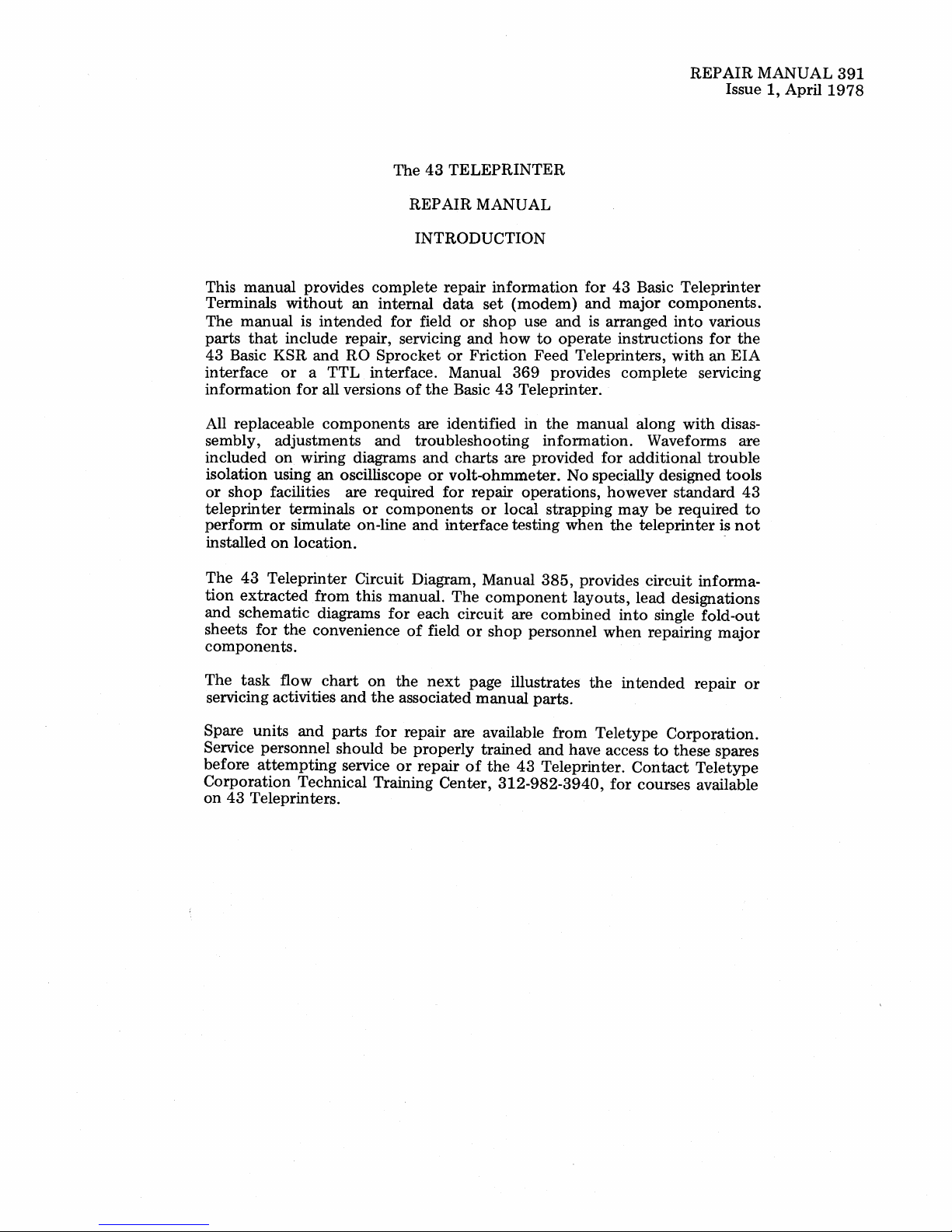
The
43
TELEPRINTER
REPAIR
Issue
MANUAL
1,
April
391
1978
This
manual
Terminals
The
manual
that
parts
43
Basic
interface
information
provides
without
is
include repair, servicing
KSR
or a TTL
for
All replaceable
sembly,
included
adjustments
on
wiring diagrams
isolation using
or
shop
facilities are required
teleprinter
perform
installed
The
43
tion
extracted
and
schematic diagrams
sheets
terminals
or
simulate on-line
on
location.
Teleprinter Circuit Diagram, Manual
for
the
components.
complete
an
internal
intended
and
RO
for
Sprocket
interface. Manual
all versions
components
and
an
oscilliscope
or
components
from
this
manual.
for
convenience
REPAIR
MANUAL
INTRODUCTION
repair
data
field
or
and
or
Friction
information
set
(modem)
shop
how
369
of
the
Basic
43
Teleprinter.
are identified in
troubleshooting
and
charts
or
volt-ohmmeter.
for
and
interface
The
are provided
repair operations, however
or
local strapping
testing when
component
each circuit are
of
field
or
shop
for
43
and
major
use
and
is arranged
to
operate
Feed
provides
the
instructions
Teleprinters,
complete
manual along
information.
for
No specially designed
may
the
385,
provides
layouts, lead designations
combined
personnel
into
when
Basic
Teleprinter
components.
into
various
for
with
an
servicing
with
Waveforms are
additional
trouble
standard
be
required
teleprinter
circuit
single
informa-
fold-out
repairing
the
EIA
disas-
tools
43
to
is
not
major
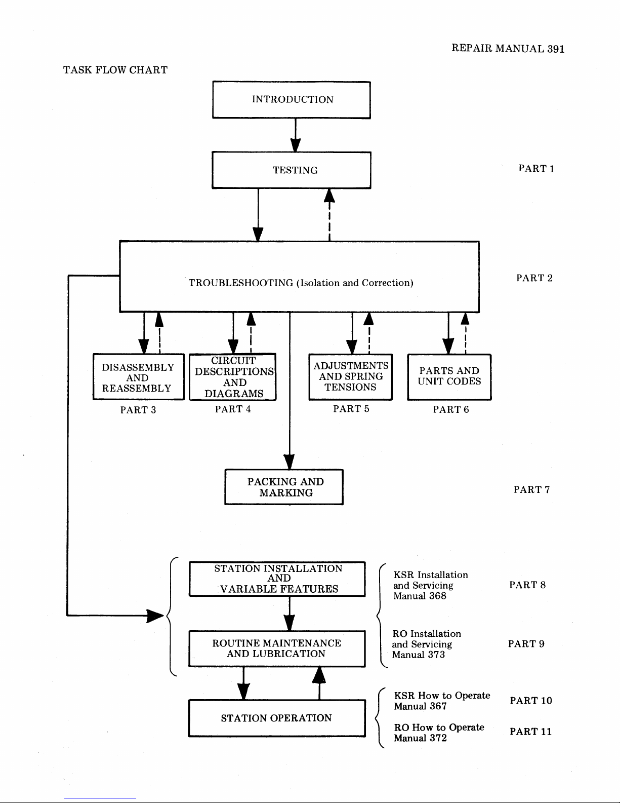
The
task
flow
chart
servicing activities
Spare
units
and
and
parts
on
the
for
Service personnel should
before
attempting
Corporation
on
43
Teleprinters.
service
Technical Training Center,
the
next
page illustrates
associated
manual
repair are available
be
properly
or
repair
trained
of
the
312-982-3940,
parts.
from
and
have access
43
Teleprinter.
the
intended
Teletype
Contact
for
courses available
repair
Corporation.
to
these spares
Teletype
or
Page 5

The
43
TELEPRINTER
REP
AIR
MANUAL
PART
PART 9
PART
PART
PART
PART
PART
PART
PART
TABLE
1
2
3
4
5
6
7
TESTING
TROUBLESHOOTING
DISASSEMBL
CIRCUIT DESCRIPTION AND DIAGRAMS
ADJUSTMENTS
PARTS
PACKING
OF
CONTENTS
Y AND REASSEMBLY
AND SPRING TENSIONS
AND UNIT CODES
AND MARKING
SUPPLEMENTAL MANUALS INCLUDED
8
KSR INSTALLATION AND
ROUTINE
SERVICING MANUAL
RO INSTALLATION AND ROUTINE SERVICING MANUAL
368
373
Issue 3
Issue 2
PART
PART
10
11
KSR HOW
RO HOW
TO
TO
OPERATE
OPERATE
MANUAL
MANUAL
367
372
Issue 2
Issue 2
Page 6
REPAIR
MANUAL
391
TASK
FLOW
CHART
+
DISASSEMBL Y
REASSEMBLY
" !
AND
PART 3
INTRODUCTION
"
TESTING
+
I
I
I
"
TROUBLESHOOTING (Isolation and Correction)
+
" !
CIRCUIT
DESCRIPTIONS
AND
DIAGRAMS
PART 4
ADJUSTMENTS
AND SPRING
TENSIONS
l
" :
PART 5
~
I
" I
PARTS AND
UNIT CODES
PART
6
PART
PART
1
2
......
~
PACKING
MARKING
r
ST ATION INSTALLATION
AND
VARIABLE
ROUTINE MAINTENANCE
AND LUBRICATION
,r
STATION
AND
FEATURES
"
.4
~
OPERATION
KSR Installation
and Servicing
Manual
RO Installation
and Servicing
Manual
KSR
How
Manual
RO
{
How
Manual
368
373
367
to
372
to
Operate
Operate
PART
PART 8
PART
PART
PART
7
9
10
11
Page 7
PART 1-TESTING
MANUAL
391,1-1
GENERAL
1.
TEST
2.
KSR
3.
OFF-LINE
V ARIABLE
CHECKOUT
A.
B.
4.
RO
OFF-LINE
V ARIABLE
CHECKOUT
A.
B. Variable
1.
GENERAL
1.01
RO
Teleprinter.
1.02
nents
are
operate
ating
conditions.
1.03
not
provided in
is
found
and
is
used
this
in
CONTENTS PAGE
....................
EQUIPMENT
TESTING
TESTS
FEATURES
...................
Loopback
Variable Features
TESTING
TESTS
FEATURES
...................
Loopback
This
part
provides testing
and
procedures
The
information
determine
if
operating
for
extended
Endurance,
electrical
parameter
this
to
some
extent
to
isolate
part.
.............
.................
...............
Mode
............
Checkout
..................
...............
Mode
Features
properly
for
in
th~
terminal
periods
............
Checkout
the
this
and
under
environmental
testing
part.
This
type
in
Part
2,
and
correct
...
requirements
43
Basic
KSR
part
is
intended
and
its
compo-
will
continue
normal
oper-
extreme
information
of
information
Troubleshooting
troubles
indicated
12
12
12
15
15
20
20
20
and
to
to
or
is
(b) A questionable
teleprinter
1
2
repair.
(c) A questionable teleprinter, in service
received
3
3
properly
1.05
or
requires repair.
Following installation
ance calls
this
part
or
an
HTO
manual should
the
teleprinter
1.06
On
is operational.
trouble
verification
test
station
isolate
After
confined
1.07
(if available) should
the
trouble
correction
to
the
specific
The
checkout
table
form
in a specific sequence. A response is given
verify
the
test
condition
1.08
factory
1.09
step
performed
factory,
1.10
Always
given.
results
If
the
in
any
to
make sure
properly.
refer
to
Teleprinters
minal
perform
The
of
indicated
step
Data
locally developed
and
procedures
If
test
station
procedure
Note:
late
The
most
to
is
should
local
on-line
component
operates
from a customer,
at a location,
installation
be
performed
calls, a local
test
under
within
or
of a trouble,
area
that
routines
with
test
has
passed.
the
test
steps are based
installed
properly
or
routine
either
checkout
to
test
the
direction
be
performed
to
the
the
was failing.
are
presented
conditions
tests in
or
requires
is
operating
mainten-
the
testing
using
make
or a trouble
teleprinter.
test
may
arranged
the
on
all previous steps.
response is
of a test
that
the
If
the
procedure,
procedure
results
not
repeat
are
still unsatis-
obtained
has
Page 2-1, Troubleshooting.
with
TAUs
Unit
must
external
perform
remote, a copy
be
available
tests
specified
tests
for
or
be
testing
actual
at
the
in
these
with
no
associated
arrangements
On-Line Tests.
of
the
test
station.
this
part
teleprinters.
in
the
or
in
the
sure
of
a
to
be
in
to
order
satis-
the
been
Ter-
with
testing
simu-
1.04
The
testing
should
normally
(a) A repaired
before
being
information
be
used
teleprinter
returned
is
placed in service.
provided herein
to
determine
operating
properly
to a customer
if:
or
--1.11
Before
the
remote
an
on-line
testing
vided with advance details
under
terminal
option
test,
such as,
(KSR
exceptions
telephone
or
RO) (friction
present,
test
station
about
speed,
can
be
must
the
number,
or
etc.
performed,
be
pro-
teleprinter
type
of
sprocket)
Page 8
391,
1-2
1.12
Before proceeding
procedure,
(a) Is
grounded
teleprinter
check
and
(b) Are all cable
(c) Are
printer
with
the
following:
connected
polarized ac
connectors
paper
and
the
to
outlet?
fully seated?
ribbon
installed?
(d) Are
Page
to
2-1.
Manuals
any
option
(Part 8 or
exceptions
368
(KSR)
9)
present?
and
Procedures in Off-Line Tests are based
factory
exceptions
as
furnished
shown
options
are present,
in
the
KSR
being present.
the
test
response will
or
RO
Variable
Checkout.
1.13
index
head
All references
second delay,
two
character
indicates
the
to
to
spaces
next
columns
allow
the
to
the
character
are
right.
position
printed.
2.
TEST
EQUIPMENT
and
2.01 Off-Line
cedures are provided
Tests where
are
not
connector
external
available.
terminals, as follows, should
Variable
communication
To
perform
Feature
to
simulate On-Line
these
checkout
a properly
properly
373
(RO),
on
standard
If
option
Features
after
a one-
print
head
The
Test pro-
test
devices
tests,
be
strapped
Refer
be
to
print
to
be
the
before
proceeding
terminals should
specified
Note:
during
Contact
Department,
a
43
Teleprinter
vides
:S
5
6
25)
7)
4)
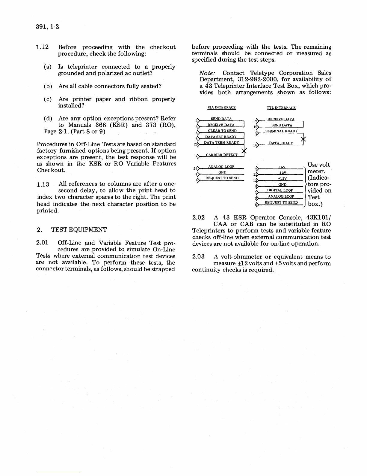
2.02
Teleprinters
checks off-line
devices are
2.03
both
EIA INTERFACE
SEND DATA
RECEIVE DATA
CLEAR TO SEND
DATA SET READY
DATA TERM READY
ANALOG LOOP
GND
REQUEST TO SEND
A
43
KSR
CAA
or
to
not
A
volt-ohmmeter
arrangements
perform
when
available
measure ±12 volts
continuity
checks is required.
with
the
tests.
be
connected
the
test
steps.
Teletype
312-982-2000,
Interface
~~
.:
V
11)
1~
~
1)
3)
6)
Test
TTL
INTERFACE
RECEIVE
SEND DATA
TERMINAL READY
DATA READY
DIGITAL LOOP
ANALOG LOOP
REQUEST TO SEND
Operator
CAB
can
be
tests
external
for
on-line
or
equivalent means
and
+5 volts
The
remaining
or
measured as
Corporation
for
availability
Box, which pro-
shown
as follows:
DAT,&
f
+5V
·12V
+12V
GND
Console,
substituted
and
variable
communication
Use
meter.
(Indicators
vided
Test
box.)
43K101/
in
feature
operation.
and
perform
Sales
of
volt
pro-
on
RO
test
to
Page 9
3.
KSR TESTING
OFF-LINE TESTS
TABLE A
OFF-LINE TEST PROCEDURES
MANUAL
391,1-3
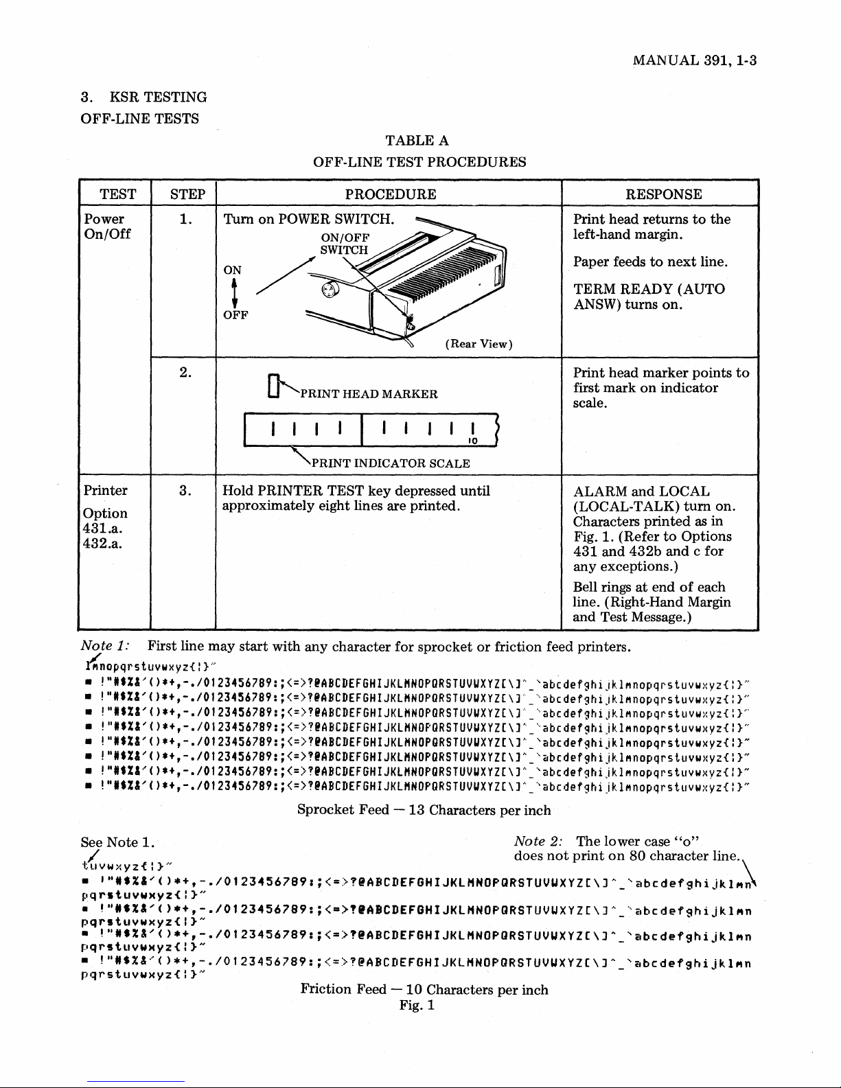
TEST
Power
On/Off
Printer
Option
431.a.
432.a.
STEP
1.
2.
3.
PROCEDURE
ON
t
OFF
(Rear
~PRINT
HEAD
MARKER
I 10
"PRINT
Hold
PRINTER
approximately eight lines are printed.
INDICATOR
TEST
key
SCALE
depressed
View)
until
~
RESPONSE
Print
head returns
left-hand margin.
Paper feeds
TERM
ANSW)
Print
first
mark
scale.
ALARM
(LOCAL-TALK)
Characters
Fig.
1.
431
and
any
exceptions.)
Bell rings
line. (Right-Hand Margin
and
Test Message.)
to
READY (AUTO
turns
head
marker
on
and
printed
(Refer
432b
at
end
to
next
line.
on.
points
indicator
LOCAL
turn
as
to
Options
and c for
of
each
the
on.
in
to
Note
1:
First line
~nopqrstuvwxyZ{:
• ".tX&/().+,-.IOt23456789:;<=>!@ABCDEF6HIJKLMNOPDRSTUVUXYZ(\]h_'abcdefghiJklMnopqrstuvwxyz{
• ".tX&'()*+,-.IOt23456789:;<=>?@ABCDEFGHIJKlHNOPURSTUVUXYZ[\)'_'abcdefghiJklMnopqrstuvwxyz{
• ".tX&'()*+,-.IOt23456789:;<=>!@ABCDEF6HIJKLHNOPDRSTUVUXYZ[\]'_'abcdefghijklMnopqrstuvwxyz{ }P
• "'$X&'().+,-.I0123456789:;<=>?@ABCDEF6HIJKLHNOPDRSTUVUXYZ(\]h_'abcdefghijklMnopqrstuvwxyz{
• ".tX&'().+,-.IOt23456789:;<=>?@ABCDEF6HIJKLHNOPGRSTUVUXYZ[\]h_'abcdefghijklMnopqrstuywxyz{
• "'$X&'()*+,-.IOt23456789:;<=>?@ABCDEF6HIJKLMNOPGRSTUVUXYZ[\]h_'abcdefghijklMnopqrstuvwxyz{
• "ItX&'().+,-.IOt23456789:;<=>?@ABCDEF6HIJKlMNOPGRSTUVUXYZ[\]A_'abcdefghijklMnopqrstuvwxyz{
• "'$%&'().+,-.IOt23456789:;<=>?@ABCDEF6HIJKLMNOPDRSTUVUXYZ[\]h_'abcdefghijklMnopqrstuvwxyz{
Note
See
/ does
"tllVW>:YZ{:}"
•
'"I.X&'().+,-./01234567891;<=>?@ABCDEFGHIJKlHNOPQRSTUVUXYZC\J~_'abcdefghiJkl"~
pqrstuyw)(yz{I}"
•
~"I.X"().+,-.I0123456789:;<=>"ABCDEFGHIJKlHNOPQRSTUVUXYZC\]h_'abcdefghiJkl"n
pqrstuywxyz{!}"
•
!"N.X&'()*+,-./0123456789:;<=)?IABCDEFGHIJKlHNOPQRSTUVUXYZC\JA_'abcdefghijkl"n
pqrstllYW)(Yz{:}"
•
!"N.%&~()*+,-./Ot23456789:;<=)?@ABCDEFGHIJKlHNOpaRSTUVUXYZ(\JA_'~bcdefghijkl"n
pqrstllYWXYz{:}-"'
1.
may
}
....
start
with
any
character
Sprocket Feed -
Friction Feed
for
13
-10
Fig. 1
sprocket
Characters
Characters
or
friction feed printers.
per
inch
Note
2:
The lower case
not
print
per
inch
on
80
character line.
}N
}H
}H
}H
}N
}N
}N
"0"
\
Page 10
391,
1-4
KSR OFF-LINE TEST (Cont)
TABLE A (Cont)
OFF-LINE TEST PROCEDURES
TEST
Printer
(Cont)
Operator
Console
STEP
4.
5.
6.
PROCEDURE
Release
Hold CTRL
PRINTER
key
depressed
TEST key.
key.
Place CAPS LOCK
Starting with
to
right, depress unshaded keys
key
in
top
row and moving from
and
depress RETURN
DOWN position.
left
in
Fig. 2.
RESPONSE
ALARM
turns
off.
Character printing stops.
Print head is
left-hand margin
to
feeds
Characters
next
printed
returned
and
line.
as
to
paper
in
Fig. 3.
TEST STEP
Operator
Console
(Cont)
7.
8.
9.
Fig. 2
1234567890-+'OWERTYUIOP=\ASDFGHJKL;~{ZXCVBNM,.1
Fig. 3
'1
23456?890-+
···qwer'tyuiop:=\asdf'3hjkl;··
{z;.:cvbnf"l,
.1
Fig. 4
TABLE A (Cont)
OFF-LINE TEST PROCEDURES
RESPONSE
head
is
Depress RETURN
PROCEDURE
and
then
LINE
FEED
key.
Print
left-hand margin
feeds
to
next
Depress
to
left
Depress RETURN and
and
release CAPS LOCK
UP position. Starting with
to
right, depress each unshaded
then
top
LINE
key
row
key
FEED
so
it
returns
and
moving
in Fig. 2.
key.
Characters
printed
Fig. 4.
Print head returns
hand
margin
to
next
line.
returned
and
line.
as
to
and
paper
to
paper
in
left-
feeds
Page 11
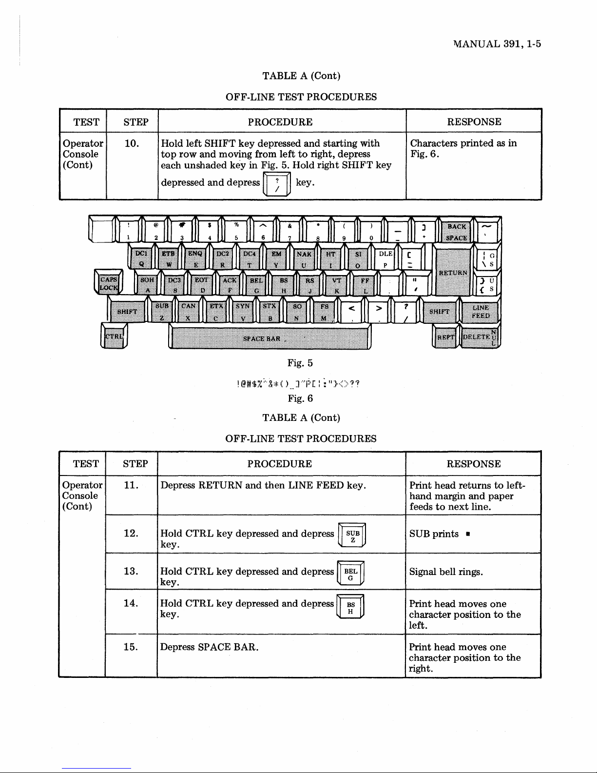
TABLE A (Cont)
OFF-LINE TEST PROCEDURES
lV1ANUAL
391,
1-5
TEST STEP
Operator
Console
(Cont)
10.
PROCEDURE
Hold left SHIFT key depressed and starting with
top
row and moving from left
each unshaded
depressed
key in Fig. 5. Hold right SHIFT key
and
depress
!
@#$:.~
rn
;"
(~:t:
Fig. 5
( )
... ] ....
Fig. 6
to
right, depress
key.
1:·
[ : :
II
}<>
'?'f
RESPONSE
Characters printed
Fig.
6.
as
in
TEST STEP
Operator
Console
(Cont)
II.
12.
13.
14.
15.
TABLE A (Cont)
OFF-LINE TEST PROCEDURES
PROCEDURE
Depress RETURN and then LINE FEED key.
Hold
CTRL
key.
Hold
CTRL
key.
Hold
CTRL
key. H
Depress SPACE BAR.
key
key
key
depressed
depressed
depressed
and
and
and
depress
depress
depress
~
S~B
~
"ilL
rn
~
~
RESPONSE
head returns
Print
hand margin and paper
feeds
to
next
SUB prints 8
Signal bell rings.
Print head moves
character position
left.
Print head moves
character position
right.
line.
to
one
to
one
to
left-
the
the
Page 12

391,1-6
KSR OFF-LINE TESTS (Cont)
TABLE A (Cont)
TEST
Operator
Console
(Cont)
Cover
Inter-
lock
Right
Margin
and
Signal
Bell
STEP
16.
17.
18.
19.
20.
21.
OFF-LINE TEST
PROCEDURE
Depress BACK SPACE key.
Depress LINE FEED key.
Depress
Depress TERM READY
Raise cover.
Close cover.
Depress RETURN and
Space
(See
Space
and
print
1.13)
print
hold
head
head
REPT and
(AUTO ANSW) key.
the
to
column
to
column
PROCEDURES
rn
LINE
125
73
keys.
FEED
(sprocket feed).
(friction feed).
key.
RESPONSE
head
is
printed
is
reached.
turns
to
next
moves
Print
character position
left.
Paper feeds
The k
of
line
, Signal bell rings
line.
TERM READY
ANSW) goes off. LOCAL
(LOCAL-TALK)
ALARM
ALARM goes off.
Print head returns
hand margin
feeds
to
and
line.
one
to
next
until
at
end
(AUTO
and
on.
to
paper
line.
the
end
of
left-
Margin
Set
and
Clear
(Remem-
ber
Lower
Case)
22.
23.
24.
25.
Depress
Depress
Depress
Depress
Depress SPACE BAR nine times.
Depress
(ESCL lower case.)
~
""Ii'
~
key.
SPACE BAR six times.
SPACE BAR
ESC
and
ESC and
then
then
two
times.
~
c~
~
rn
L
key. (ESCx)
key.
Signal bell operates as
is
character b
printed.
Signal bell does
Print head moves six
ate.
character positions
right.
Signal bell operates
times.
Print head returns
left-hand margin and indi-
cates beginning
Print head moves
Column 10.
being
not
of
to
oper-
to
two
to
line.
the
Page 13

TABLE A (Cont)
OFF-LINE
TEST
PROCEDURES
MANUAL
391,
1-7
TEST
Margin
Set
and
Clear
(Cont)
STEP
26.
27.
28.
29.
30.
3l.
PROCEDURE
Space
print
head
to
Column
Depress ESC and
Depress
Depress BACK SPACE key.
Space
Depress SPACE BAR.
Depress
Depress ESC
Depress SPACE
Depress ESC
RETURN
print
SPACE BAR.
head
and
and
then
~
D~2
key.
to
Column 50.
then
m key (ESC
BAR
four
then
~
EJ:
5l.
~
key. (ESCr)
times.
~
key
m
(ESCw).
)·
RESPONSE
Print
head
returns
margin
Signal bell rings.
Signal bell operates.
Print
5l.
Signal bell rings.
Print
Column
Print
Column
Print
hand
and
(Column
head
head
head
head
margin
paper
indicates
remains
5l.
moves
55.
returns
(Column
feeds
10).
to
to
to
to
left
Column
at
left-
10)
next
line.
Turn
off
before
If
connector
Loopback
proceeding
the
43
TEST
POWER switch
to
Teleprinter Interface
(TTL
or
STEP
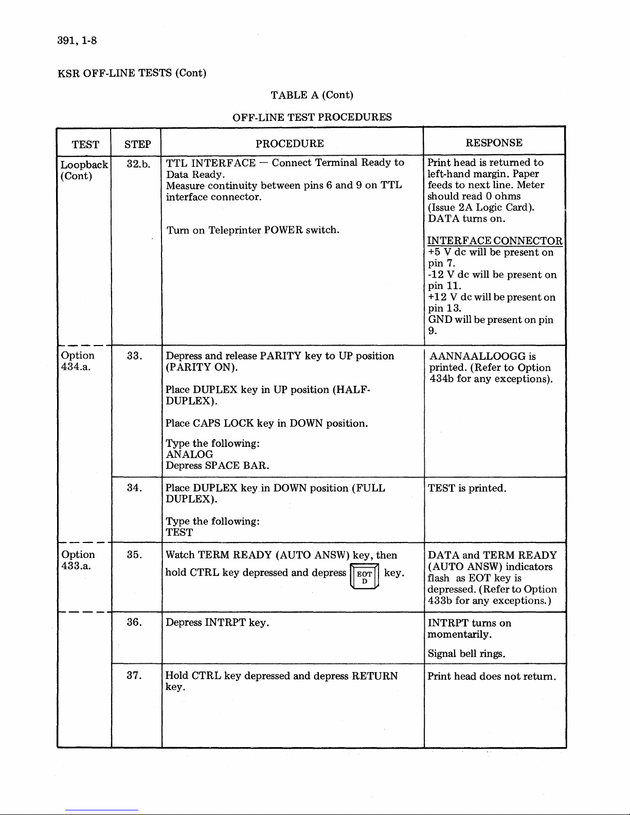
32.
~---
32.a.
and
Step
32.
EIA). See instructions furnished
Place
teleprinter
or
32
b.
1------------------
EIA
INTERFACE -Connect
Term
Ready.
Turn
on
connect
Test
Teleprinter
the
Box
OFF-LINE
test
arrangement
is available,
TABLE A (Cont)
TEST
PROCEDURE
in
loopback
POWER switch.
shown
connect
with
mode:
Carrier
the
test
box.
PROCEDURES
Perform 32 a
Detect
test
on
to
box
Data
Page 1-2
to
to
the
teleprinter
1----------
Print
left-hand margin.
feeds
turns
EIA
INTERFACE
CONNECTOR
+
12
V will
pin 4 (Issue
GND will be
pin
7.
the
interface
RESPONSE
head is
to
on.
next
be
2A
returned
line.
present
connector
interface
to
Paper
DATA
present
Logic Card)
on
on
Page 14
391,
1-8
KSR OFF-LINE TESTS (Cont)
TABLE A (Cont)
OFF-LINE TEST PROCEDURES
TEST
Loopback
(Cont)
----
Option
434.a.
STEP
32.b.
33.
TTL
INTERFACE -
Data
Ready.
Measure
interface
Tum
Depress
(PARITY ON).
Place DUPLEX
DUPLEX).
Place CAPS LOCK
continuity
connector.
on
Teleprinter POWER switch.
and
release PARITY
key
PROCEDURE
Connect
between
in
UP
key
in DOWN position.
Terminal Ready
pins 6
key
position (HALF-
and 9 on
to
UP position
to
TTL
RESPONSE
Print
head
is
returned
left-hand margin. Paper
feeds
to
next
line. Meter
0
should read
(Issue
2A
DA T A
INTERFACE
+5 V
pin
-12
pin
+
pin
GND will
9.
AANNAALLOOGG is
printed.
434b
turns
dc
7.
V
dc
II.
12 V dc
13.
for
ohms
Logic Card).
on.
CONNECTOR
will be
will
(Refer
present
be
will
be
be
present
to
any
exceptions).
present
present
on
Option
to
on
on
on
pin
----
Option
433.a.
----
34.
35.
36.
37.
Type
the
following:
ANALOG
Depress SPACE BAR.
Place DUPLEX key.in DOWN position
DUPLEX).
Type
the
following:
TEST
Watch TERM READY (AUTO ANSW)
hold
CTRL
Depress
Hold
key.
INTRPT
CTRL
key
key
depressed
key.
depressed
and
depress
and
depress RETURN
(FULL
key,
then
~
E~T
~
key.
TEST is
DATA
(AUTO ANSW) indicators
flash as
depressed.
433b
INTRPT
momentarily.
Signal bell rings.
Print
printed.
and
TERM READY
EOT key
(Refer
for
any exceptions.)
turns
on
head
does
not
is
to
Option
return.
Page 15
MANUAL
391,
1-9
TEST
Loopback
(Cont)
Option
435.a.
Option
435.a.
STEP
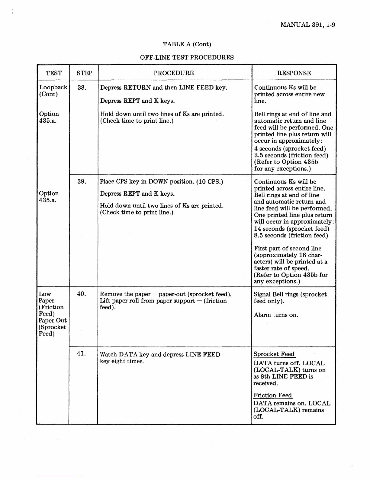
38.
39.
OFF-LINE TEST PROCEDURES
PROCEDURE
Depress RETURN and
REPT
and
Depress
down
time
CPS
until
key
Hold
(Check
Place
Depress REPT
down
Hold
(Check time
until
to
K keys.
two
to
print
line.)
in
DOWN position. (10 CPS.)
and
K keys.
two
print
line.)
TABLE A
then
LINE FEED key.
lines
of
lines
of
(Cont)
Ks
are printed.
Ks
are printed.
RESPONSE
Continuous
printed
Ks
will
across entire
be
new
line.
at
end
of
line
Bell rings
automatic
feed will
printed
occur
be
line plus
in approximately:
return
performed. One
return
and
and line
will
4 seconds (sprocket feed)
2.5 seconds (friction feed)
to
(Refer
for
Option
any exceptions.)
Continuous
printed
Bell rings
and
across
at
automatic
line feed will
One
printed
will occur
14
seconds (sprocket feed)
8.5
seconds (friction feed)
in
435b
Ks
will
be
entire
line.
end
of
line
return
be
line plus
and
performed.
return
approximately:
Low
Paper
(Friction
Feed)
Paper-Out
(Sprocket
Feed)
40.
41.
the
Remove
paper
Lift paper roll from
feed).
Watch DATA key
key eight times.
- paper-out (sprocket feed).
paper
support
and
depress LINE
- (friction
FEED
part
of
First
second
(approximately
rate
to
be
of
speed.
Option
acters) will
faster
(Refer
any
exceptions.)
line
18
char-
printed
435b
at
for
Signal Bell rings (sprocket
feed only).
turns
Alarm
on.
S:Qrocket Feed
DATA
(LOCAL-TALK)
as
8th
turns
LINE
off. LOCAL
turns
on
FEED
is
received.
Friction Feed
on.
DATA remains
(LOCAL-TALK)
LOCAL
remains
off.
a
Page 16
391,1-10
KSR
OFF-LINE
TESTS
(Cont)
TEST
Low
Paper
(Friction
Feed)
Paper-Out
(Sprocket
Feed)
(Cont)
Loopback
Clear
Analog
Loop
STEP
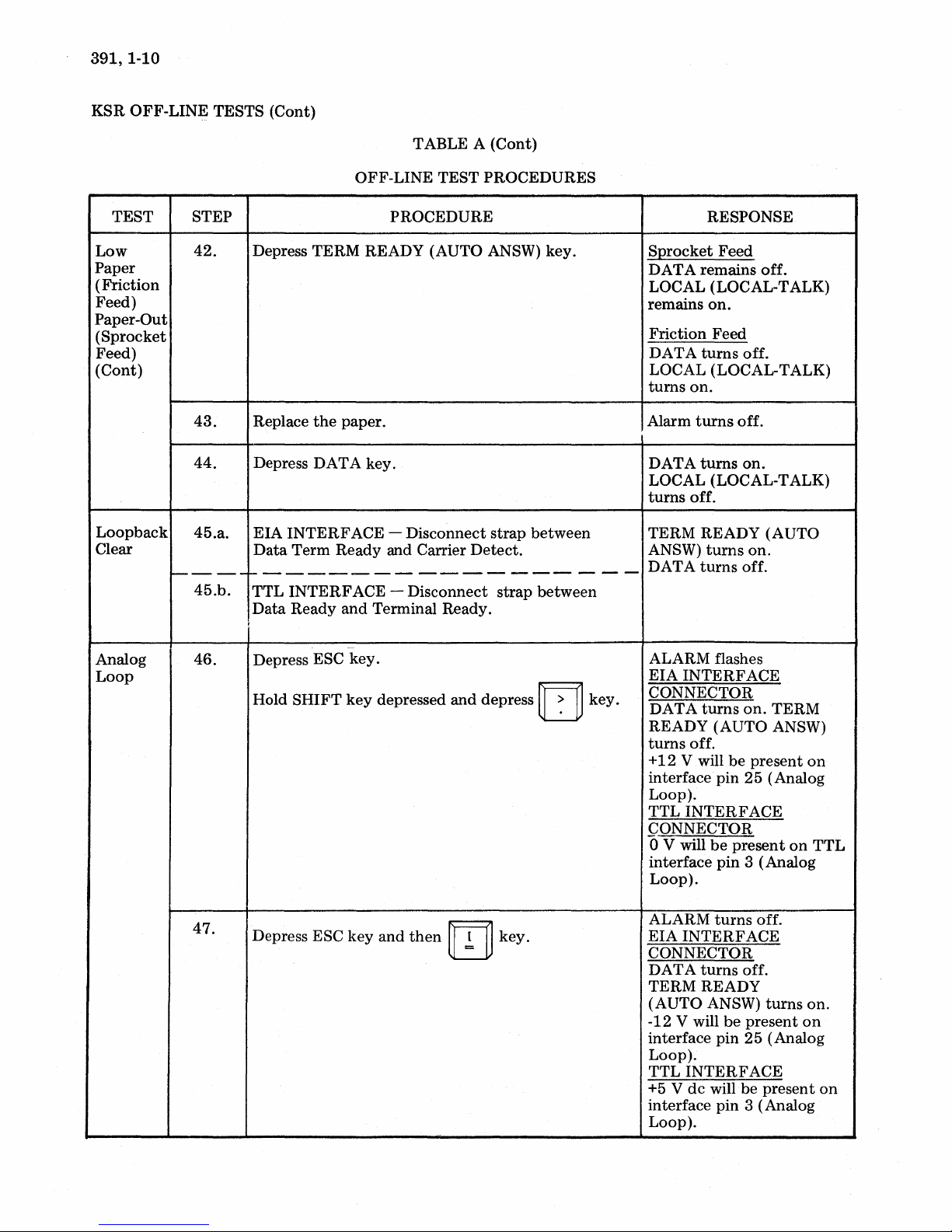
42.
43.
44.
45.a.
----
45.b.
46.
TABLE A
OFF-LINE
PROCEDURE
Depress
Replace
Depress
EIA
Data
TERM
the
DATA
INTERFACE -Disconnect
Term
READY (AUTO ANSW)
paper.
key.
Ready
and Carrier
TEST
------------------
TTL
INTERFACE -Disconnect
Data
Ready
I
Depress ESC
Hold
SHIFT
and
Terminal Ready.
-
key.
key
depressed
and
(Cont)
PROCEDURES
key.
strap
between
Detect.
strap
between
depress IT]
key.
RESPONSE
SQrocket
DATA
LOCAL (LOCAL-TALK)
remains
Friction
DA
LOCAL (LOCAL-TALK)
turns
Alarm
DATA
LOCAL (LOCAL-TALK)
turns
TERM
ANSW)
DATA
ALARM flashes
EIA
CONNECTOR
DATA
READY
turns
+12
interface
Loop).
TTL
CONNECTOR
o V will
interface
Loop).
Feed
remains
on.
Feed
T A
turns
off.
on.
turns
off.
turns
on.
off.
READY
turns
on.
turns
off.
INTERFACE
turns
on.
(AUTO
off.
V will
be
present
pin
25
INTERFACE
be
present
pin
3 (Analog
off.
(AUTO
TERM
ANSW)
(Analog
on
on
TTL
47.
Depress ESC
key
and
then
m
key.
ALARM
EIA
CONNECTOR
DATA
TERM
(AUTO
-12 V will
interface
Loop).
TTL
+5 V
interface
Loop).
turns
INTERFACE
turns
off.
READY
ANSW)
be
pin
25
INTERFACE
dc
will be
pin
3 (Analog
off.
turns
present
(Analog
present
on.
on
on
Page 17
MANUAL
391,
1-11
TEST
Digital 48.
Loop
Low
Paper
(Friction
Feed)
Paper-Out
(Sprocket
Feed)
STEP
49.
50.
51.
TABLE A
OFF-LINE
PROCEDURE
TTL
INTERFACE
Hold
SHIFT
TTL
INTERFACE
then
m key.
Sprocket
Friction
support.
Depress TERM READY (AUTO ANSW) key.
key
Feed
- Remove paper.
Feed -Lift
~
depressed
TEST
- Depress ESC key.
- Depress ESC key
paper
(Cont)
PROCEDURES
and
depress
roll from
paper
rn
roll
key
RESPONSE
o V will
interface pin 1 (Digital
Loop).
+5 V
TTL
(Digital
Signal bell rings
feed only).
TERM
ANSW)
LOCAL (LOCAL-TALK)
and
TERM
ANSW)
LOCAL (LOCAL-TALK)
and
be
present
dc
will
interface
Loop).
READY
turns
ALARM
READY
remains off.
ALARM
be
present
pin 1
(sprocket
(AUTO
off.
turn
(AUTO
remain
on
on.
TTL
on.
on
52.
53.
This
completes
ON-LINE testing.
the
Replace
Place CPS
Place DUPLEX
DUPLEX).
OFF-LINE
the
test
paper.
key
in
of
UP
key
the
position
in
UP
position
43
KSR
(30
CPS)
(HALF-
Teleprinter. Use local
ALARM
procedures
turns
off.
and
arrangements
for
Page 18
391,1-12
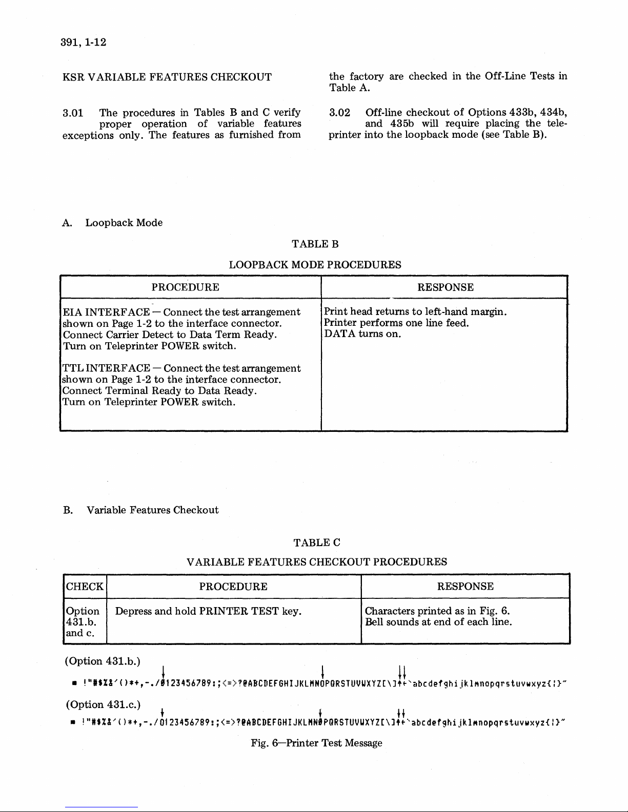
KSR VARIABLE FEATURES CHECKOUT
the
factory are checked in
Table A.
the
Off-Line Tests in
3.01
exceptions only.
A.
EIA
shown
Connect
Turn
TTL
shown
Connect
Tum
The
procedures in Tables
proper
Loopback
INTERF
on
on
INTERF
on
on
ACE - Connect
Page 1-2
Carrier
Teleprinter POWER switch.
ACE - Connect
Page 1-2
Terminal Ready
Teleprinter POWER switch.
operation
The
features as furnished from
Mode
PROCEDURE
to
the
Detect
to
to
the
Band
of
variable features
LOOPBACK MODE PROCEDURES
the
test
interface connector.
Data
Term Ready.
the
test
interface connector.
to
Data
Ready.
C verify
arrangement
arrangement
3.02
printer
TABLE B
Print head returns
Printer performs one line feed.
DATA
Off-line
and 435b will require placing
into
turns
checkout
the
loopback
on.
of
Options
mode
RESPONSE
to
left-hand margin.
(see Table B).
433b,
the
434b,
tele-
B.
Variable Features Checkout
V ARIABLE FEATURES CHECKOUT PROCEDURES
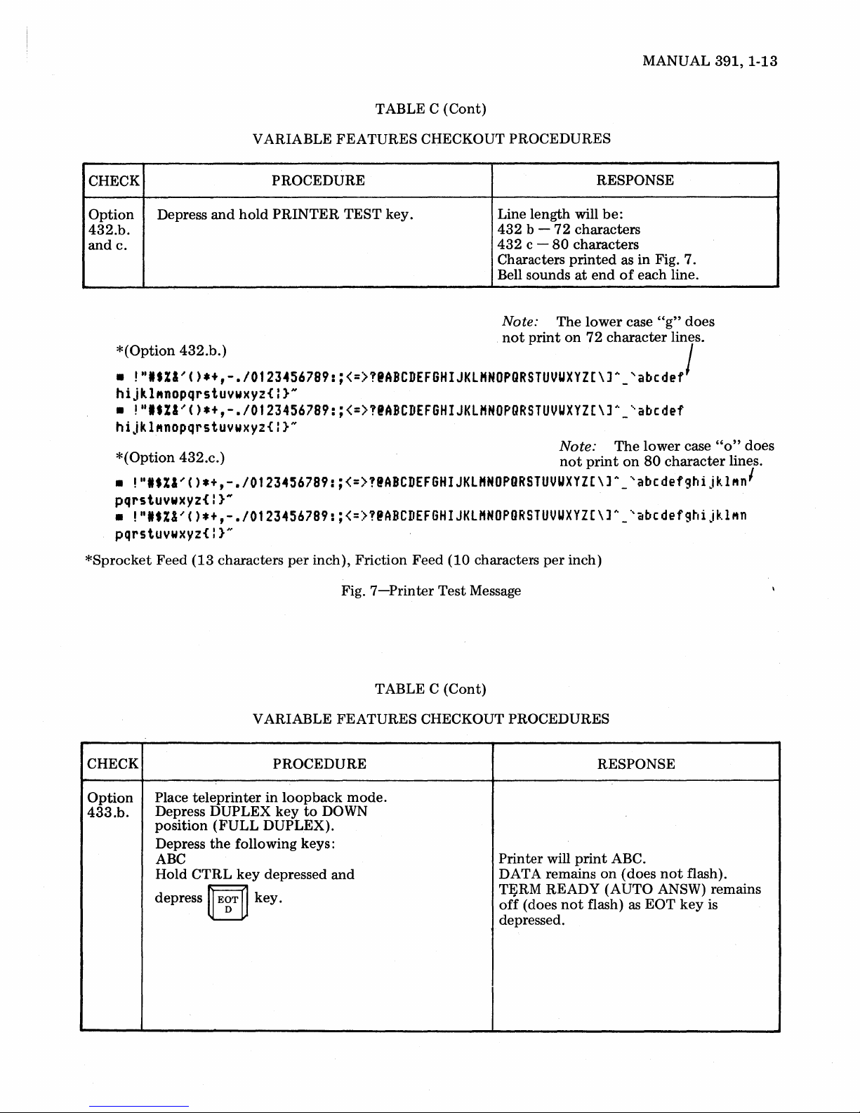
CHECK
Option
431.b.
and c.
(Option
•
!",.%&,()*+,-./J'234567B9:;<=>T@ABCDEFGHIJKLHN~PGRSTUVUXYZ[\J!!'abCdefghijkl~nOpqrstuvwXYZ{:}N
(Option
•
!"It%&'()*+,-./0123456789:;<=>?@ABCDEFGHIJKLHNIPQRSTUVUXYZ[\J
Depress
431.b.)
431.c.)
and
+ f H
PROCEDURE
hold
PRINTER
TABLE C
TEST key.
Fig.
6-Printer
Test
RESPONSE
Characters printed as in Fig. 6.
at
end
Bell sounds
Message
••
'abcdefghijkl~nopqrstuvwxY2{:}N
of
each line.
Page 19
MANUAL
391,
1-13
CHECK
Option
432.b.
andc.
*(Option
•
Depress
!"'.ZI~C)*+,-.I0123456789:;<=>!'ABCDEFGHIJKLHNOPQRSTUVUXYZ[\]A_
and
432.b.)
hijkl"nopqrstuvwxyz{I}N
•
!"'.ZI'C)*+,-.I0123456789:;<=>!@ABCDEFGHIJKLHNOPQRSTUVUXYZ[\]~_'abedef
hijkl"nopqrstuvwxyz{l}"
*(Option
•
!"'.ZI'C)*+,-.I0123456789:;<=>!@ABCDEFGHIJKLHNOPORSTUVUXYZ[\]A_'abcdefghijklMn
432.c.)
pqrstuvwxyz{I}N
•
!"'.Z&'C)*+,-.I0123456789:;<=>!@ABCDEFGHIJKLHNOPORSTUVUXYZ[\]h_'abcdefghijklMn
pqrstuvwxyz{l}"
VARIABLE
PROCEDURE
hold
PRINTER
TABLE C
FEATURES
TEST
key.
(Cont)
CHECKOUT PROCEDURES
RESPONSE
Line length will
432
b -
72
432
c -
80
Characters
Bell sounds
Note:
not
The
print
be:
characters
characters
printed
at
end
lower
on
72
Note:
not
print
as in Fig. 7.
of
each line.
case
"g"
character
'abedef
The
lower
on
80
does
lines.
/
case
character
"0"
does
lines.
'
*Sprocket
CHECK PROCEDURE
Option
433.b.
Feed
(13
characters
VARIABLE FEATURES CHECKOUT PROCEDURES
Place
teleprinter
Depress DUPLEX
position
Depress
ABC
Hold CTRL
depress
(FULL
the
ij
EgT
DUPLEX).
following keys:
key
~
key.
per
inch), Friction Feed (10 characters
in
loopback
key
to
depressed
Fig.
mode.
DOWN
and
7-Printer
TABLE
Test
Message
C (Cont)
per
inch)
will
Printer
DATA remains
TFiRM
off
(does
depressed.
print
READY (AUTO ANSW) remains
not
flash) as
RESPONSE
ABC.
on
(does
not
EOT
flash).
key
is
Page 20
391,1-14
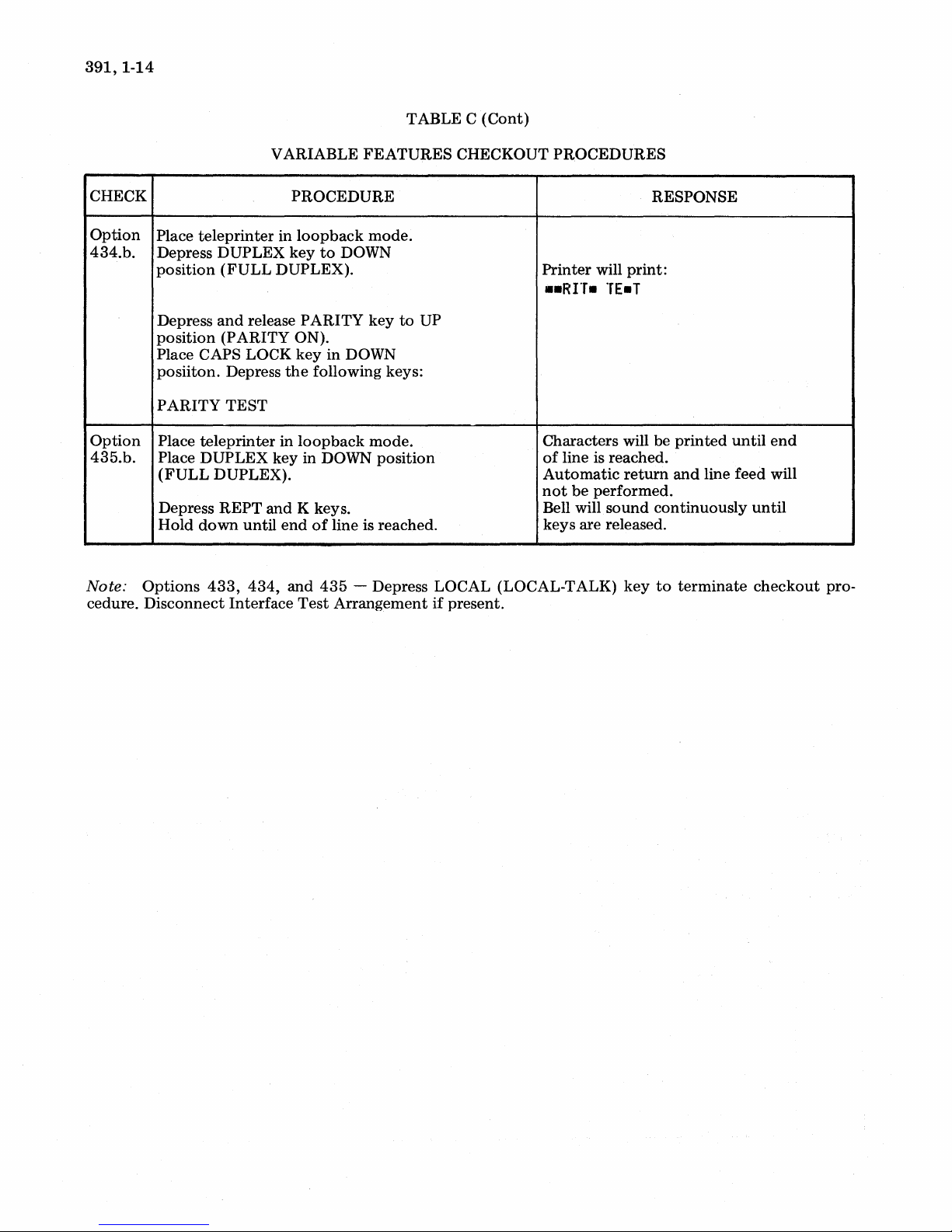
CHECK
Option
434.b.
Option
435.b.
VARIABLE
Place
teleprinter
Depress
position
Depress
position
Place CAPS LOCK
posiiton.
PARITY
Place
Place
(FULL
Depress
Hold
DUPLEX
(FULL
and
(PARITY
Depress
TEST
teleprinter
DUPLEX
DUPLEX).
REPT
down
in
DUPLEX).
release
in
key in DOWN
and
until
end
FEATURES
PROCEDURE
loopback
key
to
PARITY
ON).
key
the
following keys:
loopback
K keys.
of
mode.
DOWN
key
in
DOWN
mode.
line is reached.
TABLE C
to
UP
position
(Cont)
CHECKOUT
PROCEDURES
Printer
••
Characters
of
Automatic
not
Bell will
keys
will
print:
Rrr.
TE.T
will be
line is reached.
return
be
performed.
sound
are released.
RESPONSE
printed
and
continuously
until
line feed will
end
until
Note:
cedure.
Options
Disconnect
433,
434,
Interface
and
Test
435
- Depress LOCAL (LOCAL-TALK)
Arrangement
if
present.
key
to
terminate
checkout
pro-
Page 21
4. RO TESTING
OFF-LINE TESTS
(Cont)
OFF-LINE
TABLED
TEST
PROCEDURES
MANUAL
391,
1-15
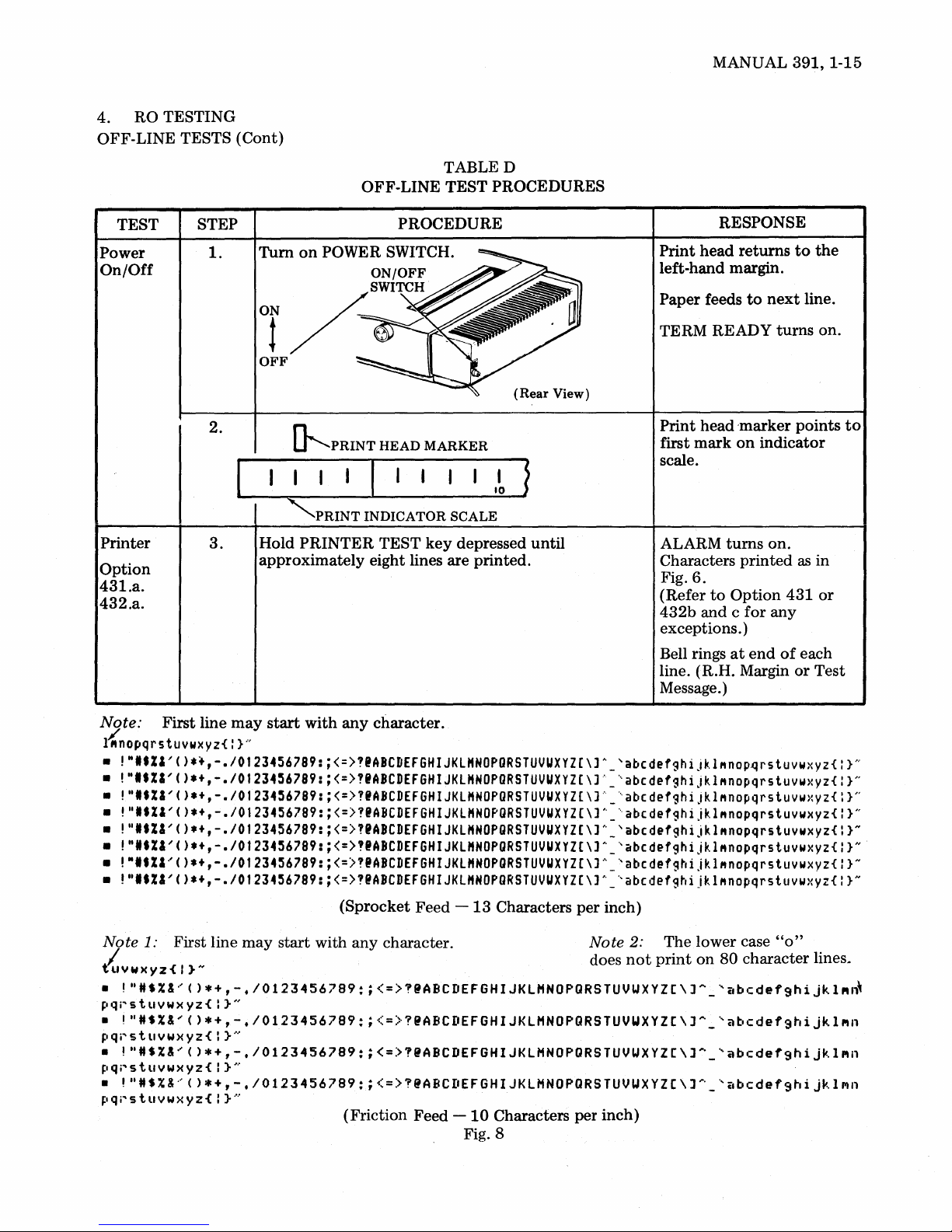
TEST
Power
On/Off
Printer
Option
431.a.
432.a.
STEP PROCEDURE
1.
Turn
on
POWER SWITCH.
2.
3.
~PRINT
"'PRINT
Hold
PRINTER
approximately
HEAD
MARKER
INDICATOR
TEST
SCALE
key
depressed
eight lines are printed.
(Rear
until
View)
RESPONSE
Print
head
returns
left-hand margin.
Paper feeds
TERM READY
Print
first
mark
to
head
'marker points
on
next
turns
indicator
scale.
ALARM
Characters
Fig.
(Refer
432b
6.
to
and c
turns
printed
Option
for
on.
any
exceptions. )
Bell rings
at
end
of
line. (R.H. Margin
Message.)
to
line.
as
431
each
or
the
on.
to
in
or
Test
Note:
l{nopqrs
•
•
•
•
• !"
•
•
•
Note
Iu
•
~lqj"stllYWXYZ{:
•
pqi"stllYwxyz{:
•
pqr'stllYwxyz{:
•
~Iqr'stllvwxyz{:
First line
may
start
with
any
character.
tuvwxyz{ : }..,
!"'.ZI'().~,-.I0123456789:·<=>?IABCDEFGHIJKLHNOPORSTUVUXYZ(\]A_'abcdefghiJkl"nop~rstuvwxyz{
!"'.ZI'()*+,-.I01234~6789:
!"'.%I'()*+,-.I01234~6789:
!"'.ZI'()*+,-./0123456789:
••
ZI'()*+,-.I0123456789:
!"'.ZI'().+,-.I01234~6789:
!"ltZI'()*+,-.I0123456789:
!"I.ZI'()*+,-.I0123456789:
1:
First line
Y W)( Y z { I } N does
!"HS%&'()*+,-.I0123456789:;<=>?@ABCDEFGHIJKlHNOPQRSTUVUXYZC\J~_'abcdef9hijkl"~
}"
may
start
<=>"ABCDEFGHIJKlHNOPORSTUVUXYZ(\]~_'abcdefghijkl"nopqrstuvwxyz{
<=>?'ABCDEFGHIJKL"NOPORSTUVUXYZ(\]~_'abcdefghiJkl"nopqrstuvwxyz{
<=>"ABCDEFGHIJKlHNOPORSTUVUXYZ[\]A_'abcdefghiJkl"nopqrstuvwxyz{
<=>?IABCDEFGHIJKlHNOPORSTUVUXYZ(\]A_'abcdefghijkl"nopqrstuvwxyz{
<=>"ABCDEFGHIJKlHNOPORSTUVUXYZ(\]A_'abcdefghijkl"nopqrstuvwxyz{
<=)?IABCDEFGHIJKlHNOPORSTUVUXYZ(\]A_'abcdefghijkl"nopqrstuvwxyz{
<=>"ABCDEFGHIJKlHNOPORSTUVUXYZ(\]A_'abcdefghijklMnopqrstuvwxyz{
(Sprocket Feed
with any character. Note
-13
Characters
per
inch)
2:
not
The lower case
print
on
80 character
"0"
}N
}N
}N
}H
}N
}N
}N
}N
lines~
!"HS%&'()*+,-.I0123456789:;<=>?@ABCDEFGHIJKlHNOPQRSTUVWXYZC\JA_'abcdefghijkl"n
}"
!"HS%&'()*+,-.I0123456789:;<=>?@ABCDEFGHIJKlHNOPQRSTUVUXYZC\J~_'abcdef9hijkl"n
!"
H S % &.' ( ) * + , - • I 0 1 2 3 4 5 6 7 8 9 : ; < = > ? @
},
}
....
..
ABC
II
(Friction Feed -
E F G H I J K l H N 0 P Q R
10
Characters per inch)
STU
V U X Y Z [ \ J
.... _ .,
it
bed
e f 9 h i j
",
1 III n
Fig. 8
Page 22
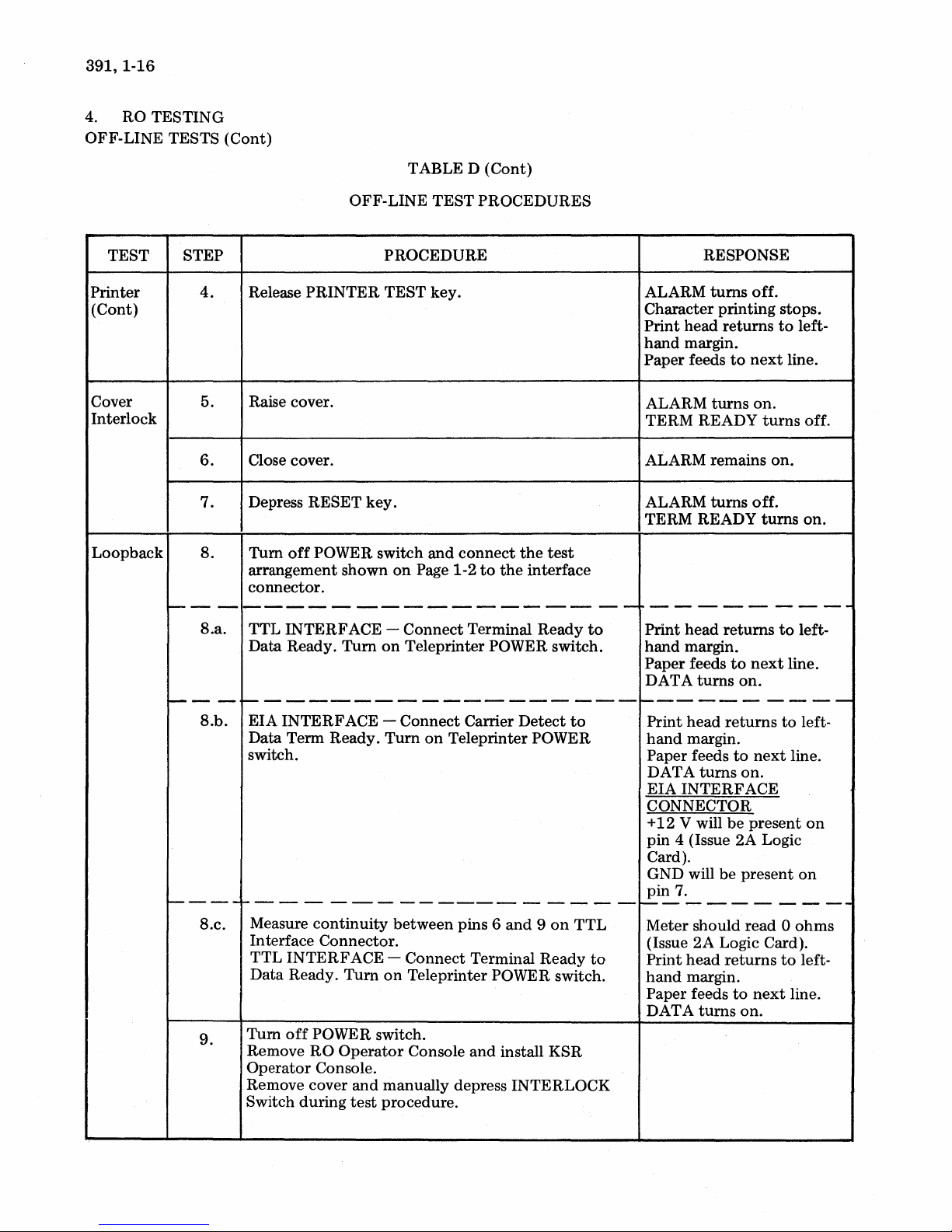
391, 1-16
RO TESTING
4.
OFF-LINE TESTS (Cont)
TABLE D (Cont)
TEST STEP
Printer
(Cont)
Cover
Interlock
Loopback
---
i---
1-----
4.
5.
6.
7.
S.
Release PRINTER TEST key.
Raise cover.
Close cover.
Depress RESET key.
Tum
off
POWER switch
arrangement shown
connector.
-----------------
S.a.
- -
S.b.
TTL INTERFACE - Connect Terminal Ready
Data Ready. Turn
~-----------------
EIA INTERFACE - Connect Carrier Detect
Data Term Ready.
switch.
1------------------
S.c.
9.
Measure
In terface Connector.
TTL INTERFACE Data Ready.
Tum
Remove
Operator Console.
Remove cover
Switch during
continuity
off
POWER switch.
RO
OFF-LINE
PROCEDURE
on
Turn
Turn
on
Operator
and
manually depress INTERLOCK
test
procedure.
TEST PROCEDURES
and
connect
on
Page 1-2
Teleprinter POWER switch.
on
between pins 6
Connect Terminal Ready
Teleprinter POWER switch.
Console
to
the
Teleprinter POWER
and 9 on
and
install KSR
the
test
interface
to
to
TTL
to
RESPONSE
ALARM
Character printing stops.
Print head returns
hand
Paper feeds
ALARM
TERM READY
ALARM remains on.
ALARM
TERM READY
10---------
--
Print head returns
hand margin.
Paper feeds
DATA
turns
margin.
turns
turns
turns
----------
Print head
hand
margin.
Paper feeds
DAT A
EIA INTERFACE
CONNECTOR
+
pin
Card).
GND will be present
pin
turns
12
V will
4 (Issue 2A Logic
7.
1-----------
Meter should read 0
(Issue 2A Logic Card).
head
Print
hand
margin.
Paper feeds
DAT A
turns
off.
to
next
on.
turns
off.
turns
to
next
on.
returns
to
next
on.
be
present
returns
to
next
on.
to
line.
to
line.
to
line.
to
line.
left-
off.
on.
left-
left-
on
on
ohms
left-
Page 23

TABLE D (Cont)
MANUAL
391,
1-17
TEST STEP
Loopback
(Cont)
~---
10.
10.a.
II.
OFF-LINE
Tum
on
POWER switch.
f----------------
Depress
(P ARITY ON).
Place DUPLEX
DUPLEX).
Place CAPS LOCK
Type
ANALOG
Depress SPACE BAR.
and
the
following:
release PARITY
key
TEST
PROCEDURE
in
UP position (HALF-
key
in
PROCEDURES
key
to
DOWN position.
UP position
--
RESPONSE
TERM READY
[TTL
7.
V will
11.
V will be
13.
9.
turns
Interface
be
present
be
be
present
ANSW)
----------
W
+5 V will
pin
-12
pin
+
12
pin
GND will
pin
AANNAALLOOGG is
printed.
(AUTO
on.
Onl~
present
present
on
on
on
on
f-----
Option
433.a.
---
12.
13.
14.
Place DUPLEX
DUPLEX).
Type
the
TEST
Watch TERM READY (AUTO ANSW) key then'
hold
CTRL
Depress
Hold CTRL
key.
INTRPT
key
following:
key
depressed
key.
key
depressed
in
DOWN position (FULL
and
depress
and
depress RETURN
~
Eg"
~
key.
TEST
DATA
(AUTOANSW)
flash as
depressed.
(Refer
for
INTRPT
tarily. Signal bell rings.
Print
return.
is
printed.
and
EOT
to
Option
any
exceptions.)
turns
head does
TERM READY'
key
is
433b
on
momen-
not
Page 24
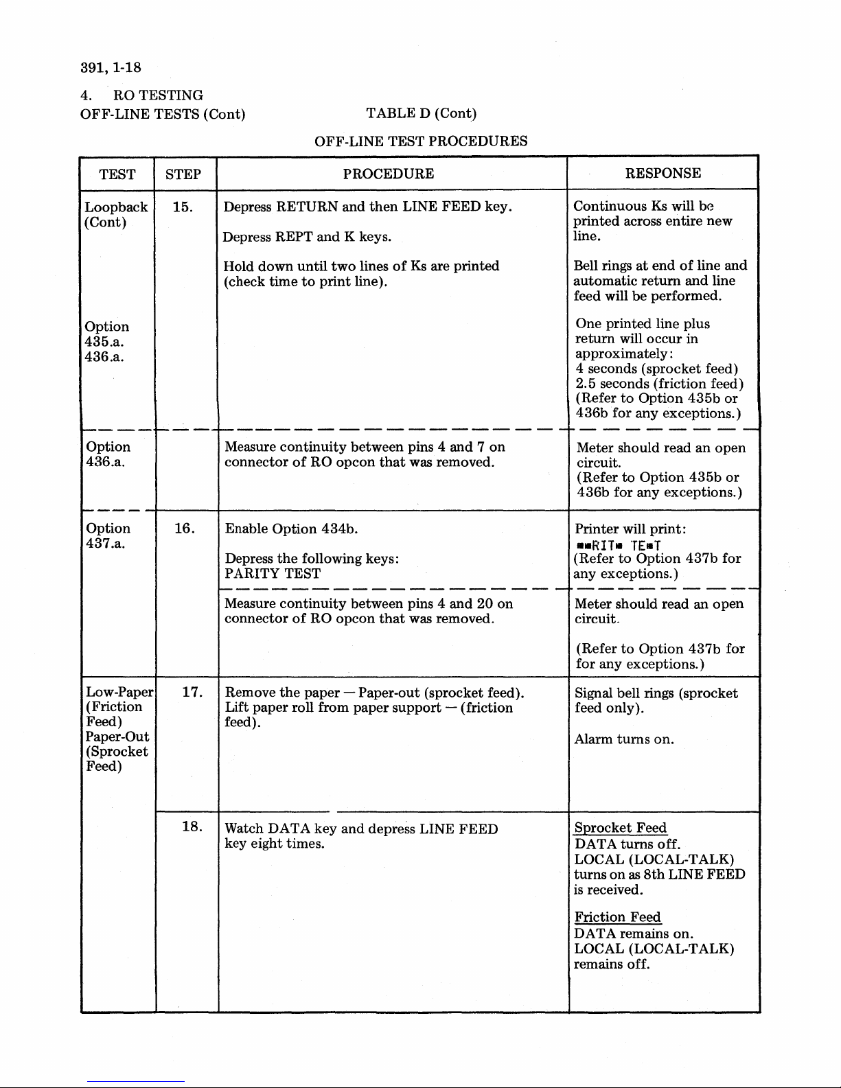
391,1-18
4. RO TESTING
OFF-LINE TESTS (Cont)
TABLE D (Cont)
TEST STEP
Loopback
(Cont)
Option
435.a.
436.a.
1-----
Option
436.a.
r---'-
1-----
Option
437.a.
15.
16.
OFF-LINE TEST
PROCEDURE
Depress RETURN and
Depress
Hold
(check time
REPT
down
and
until
to
print
K keys.
two
line).
then
lines
LINE
of
1----------------------
Measure
connector
Enable
Depress
PARITY TEST
continuity
of
RO
Option
the
434b.
following keys:
between pins 4
opcon
that
1--------------------
Measure
connector
continuity
of
RO
opcon
between pins 4 and
that
PROCEDURES
FEED
Ks
are printed
was removed.
was removed.
key.
and 7 on
20
on
RESPONSE
Continuous
printed
line.
Bell rings
automatic
feed will
One printed line plus
return
approximately:
4 seconds (sprocket feed)
2.5 seconds (friction feed)
(Refer
436b
ro-
-
-
--
Meter should read
circuit.
(Refer
436b
Printer will
..RI"T.
(Refer
any exceptions.)
---------
Meter should read
circuit.
Ks
will
across entire
at
end
of
return
be
will occur in
to
Option
for any exceptions.)
- -
to
Option
for any exceptions.)
TE.T
to
Option
and
performed.
435b
----
an
435b
print:
437b
an
be
new
line
line
open
and
or
--
open
or
for
-
Low-Paper
(Friction
Feed)
Paper-Out
(Sprocket
Feed)
17.
18.
Remove
Lift
feed).
Watch DATA key
key eight times.
the
paper
paper
roll from
- Paper-out (sprocket feed).
paper
support
and
depress LINE
- (friction
FEED
to
(Refer
for
Signal bell rings (sprocket
feed only).
Alarm
S:Qrocket Feed
DATA
LOCAL (LOCAL-TALK)
turns
is
received.
Friction Feed
DATA remains
LOCAL (LOCAL-TALK)
remains off.
Option
any exceptions.)
turns
turns
on
as
8th
437b
on.
off.
LINE FEED
on.
for
Page 25
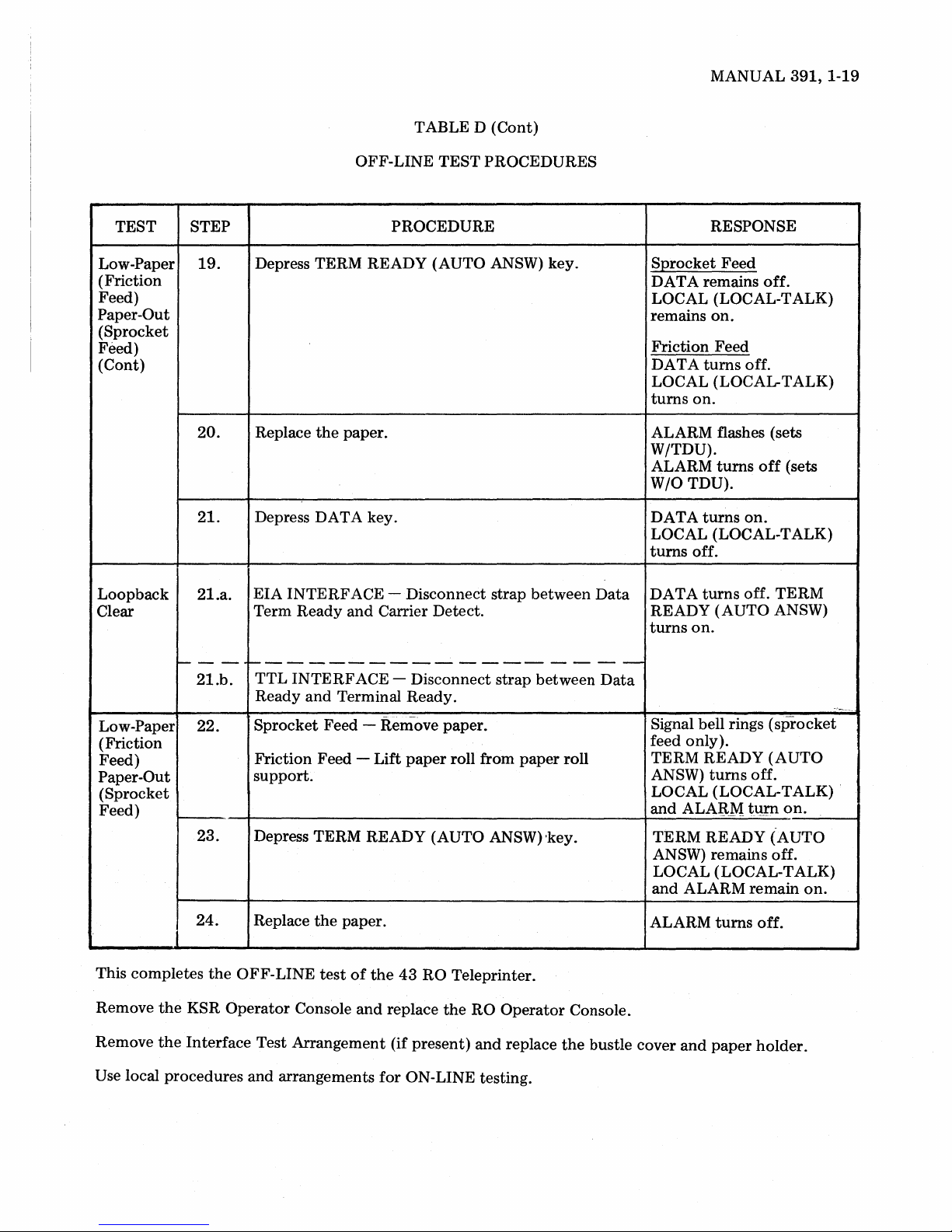
TABLE D (Cont)
MANUAL
391,1-19
TEST
Low-Paper
(Friction
Feed)
Paper-Out
(Sprocket
Feed)
(Cont)
Loopback
Clear
STEP
19.
20.
2l.
2l.a.
OFF-LINE
TEST
PROCEDURES
PROCEDURE
Depress TERM READY (AUTO ANSW) key.
Replace
the
paper.
Depress DATA key.
EIA
INTERFACE
Term
Ready
- Disconnect strap between
and
Carrier Detect.
Data
RESPONSE
SQrocket
DATA remains
Feed
off.
LOCAL (LOCAL-TALK)
remains
on.
Friction Feed
DA
T A
turns
off.
LOCAL (LOCAL-TALK)
turns
on.
ALARM flashes (sets
W/TDU).
ALARM
W/O
DATA
turns
TDU).
turns
off
on.
(sets
LOCAL (LOCAL-TALK)
turns
off.
DATA
turns
off.
TERM
READY (AUTO ANSW)
turns
on.
----
21.b.
Low-Paper 22.
~-----------------
TTL
INTERFACE
Ready
Sprocket
and
Terminal Ready.
Feed - Remove paper.
(Friction
Feed)
Paper-Out
Friction Feed -
support.
(Sprocket
Feed)
24.
This completes
the
the
KSR
Interface
Remove
Remove
23.
Depress TERM READY (AUTO ANSW) 'key.
the
the
OFF-LINE
Operator
Replace
Console
test
paper.
of
and
Test Arrangement (if present)
Use local procedures and arrangements
- Disconnect strap between
Lift
paper
roll from
the
43
RO Teleprinter.
replace
for
the
ON-LINE testing.
RO
Operator
and
replace
paper
Data
roll
Console.
the
bustle cover
Signal bell rings
(sprocket
feed only).
TERM READY
ANSW)
turns
(AUTO
off.
LOCAL (LOCAL-TALK) .
and
ALA:B.M
t\!J'Il
on.
TERM READY (AUTO
ANSW) remains off.
LOCAL (LOCAL-TALK)
and
ALARM
ALARM
and
turns
paper
remain
off.
holder.
on.
~
Page 26

391,1-20
RO VARIABLE FEATURES CHECKOUT
4.01
only. The features
are checked in
A.
Remove RO
KSR Operator Console.
EIA
; shown
Connect Carrier Detect
Tum
TTL
'shown
'Connect Terminal Ready
Tum
The procedures in Table F verify
operation
Loopback Mode
INTERF
on
Page 1-2
on
Teleprinter POWER switch.
INTERF
on
Page 1-2
on
Teleprinter POWER switch.
of
variable feature exceptions
as
furnished from
the
off-line tests in Table D.
PROCEDURE
Operator
ACE - Connect
ACE - Connect
Console and install
the
to
the
interface connector. Printer performs one line feed.
to
Data Term Ready.
to
the
interface connector.
to
Data
LOOPBACK MODE PROCEDURES
test
the
test arrangement
Ready.
the
arrangement
proper
factory
TABLE E
4.02
teleprinter
the
Console (See Table E.)
Print head returns
DATA
Off-line
through
RO
turns
into
the
Operator
on.
checkout
437b
Console
RESPONSE
to
of
Options
will require placing
loopback
left-hand margin.
mode
with
and
a KSR
433b
the
replacing
Operator
B.
Variable Features
CHECK
Option
431.b.
andc.
(Option
•
!"It%'~()*+,-./112J456789:;<=>1'ABCDEFGHIJKl"NOPORSTUVUXYZ[\]+~'abcdet9hiJklMnopqrstuvwxyz{I}N
(Option 431.c.)
•
!lIlt%,~()*+,-./m23456789:;<=>?@ABCDEFGHIJKl"N!PORSTUVUXYZ[\]ti'abCdef9hijklMnOpQrstuYWXYZ{I}N
Depress
431. b. )
Checkout
TABLE F
FEATURES CHECKOUT PROCEDURES
TEST key.
and
VARIABLE
PROCEDURE RESPONSE
hold
PRINTER
~ ~
~
Fig.
9-Printer
Test Message
Characters
Bell sounds
~~
printed
at
end
as in Fig. 9.
of
each line.
Page 27
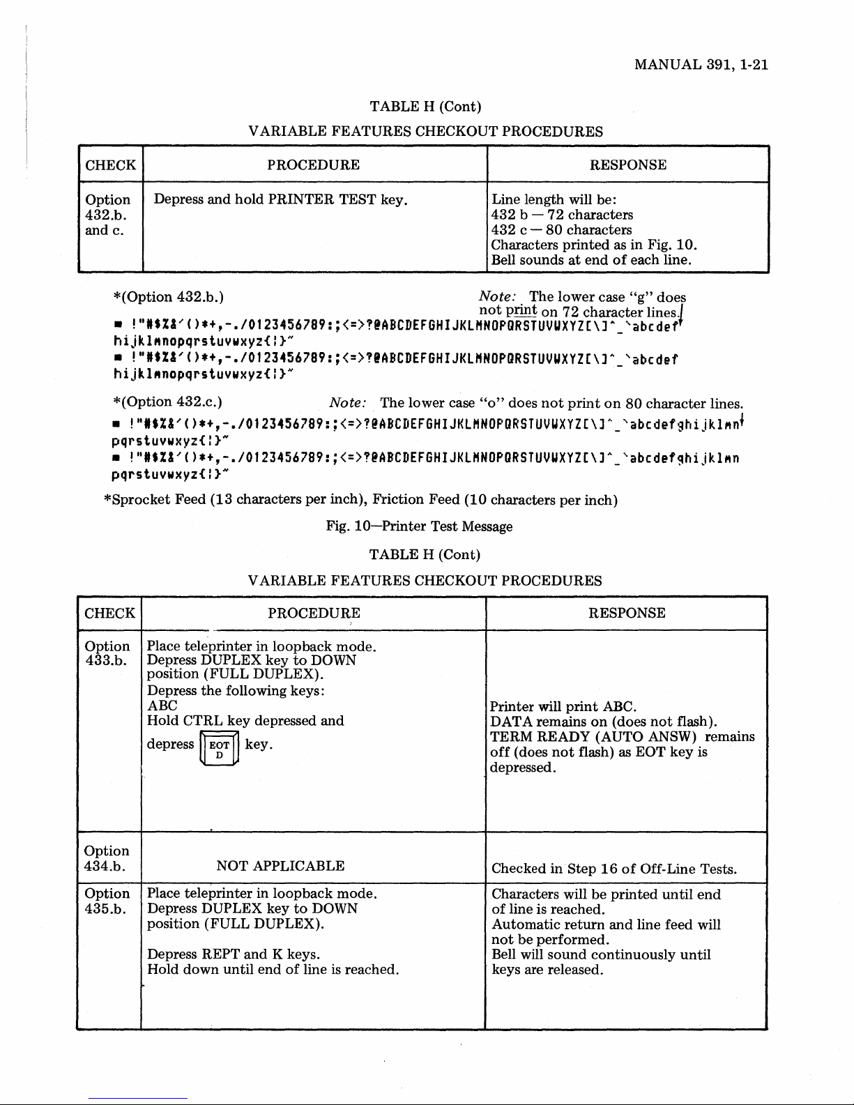
TABLE H (Cont)
MANUAL
391,1-21
CHECK
Option
432.b.
and
c.
*(Option
•
Depress
!"IS%I'()*+,-.I0123456789:;<=>?@ABCDEFGHIJKLHNOPORSTUVUXYZ[\)A
and
432.b.)
hijkl"nopqrstuywxyz{I}N
•
!ttIS%&'()*+,-.I01234S6789:;<=>?@ABCDEFGHIJKLHNOPORSTUVUXYZ[\]A_
hijkl"nopqrstuywxyz{I}N
*(Option
•
!"IS%I'()*+,-.I0123456789:;<=>1@ABCDEFGHIJKLHNOPORSTUVUXYZ[\]A_'abcdefghijkl"n
432.c.)
pqrstuywxyz{:}N
•
!"IS%I'()*+,-.I0123456789:;<=>!@ABCDEFGHIJKLHNOPORSTUVUXYZ[\]A_'abcdef~hijkl"n
pqrstuywxyz{:}N
*Sprocket
Feed
(13
V ARIABLE
PROCEDURE RESPONSE
hold
PRINTER
characters
FEATURES
TEST key.
CHECKOUT PROCEDURES
Note: The lower case
per
inch), Friction Feed
Fig.
10-Printer
Line length will be:
432
432
Characters
Bell sounds
Note: . The
not
"0"
(10
characters
Test Message
b c -
pnnt
does
72
characters
80
characters
printed
at
lower
on
72
not
print
per
end
character
inch)
as in Fig.
of
each line.
case
"g"
-'abcdef
'abcdef
on
80
10.
does
lines.J
character
lines .
f
V ARIABLE FEATURES CHECKOUT PROCEDURES
CHECK PROCEDURE
Option
433.b.
Option
434.b.
Option
435.b.
Place teleprinter in
Depress
position
Depress
ABC
Hold
depress
Place
Depress DUPLEX key
position
Depress REPT
Hold
DUPLEX key
(FULL
the
following keys:
CTRL
teleprinter
down
key
ij
EgT
NOT APPLICABLE
(FULL
until
loopback
DUPLEX).
depressed
~
key.
in
loopback
DUPLEX).
and
K keys.
end
to
to
of
line is reached.
I
mode.
DOWN
and
mode.
DOWN
TABLE H (Cont)
RESPONSE
Printer
DATA remains
TERM READY
off
depressed.
Checked
Characters will
of
Automatic
not
Bell will
keys are released.
will
print
(does
not
flash) as EOT
inStep
line is reached.
return
be
performed.
sound
ABC.
on
(does
not
flash).
(AUTO ANSW) remains
key
is
16
of
Off-Line Tests.
be
printed
and
continuously
until
end
line feed will
until
Page 28

391,1-22
RO
VARIABLE FEATURES CHECKOUT (Cont)
CHECK
Option
436.b.
Option
437.b.
VARIABLE
PROCEDURE
Place teleprinter
Depress DUPLEX
in
loopback
key
to
DOWN
position (FULL DUPLEX).
Place CPS
key
in DOWN position
(10 CPS).
Depress REPT
Hold
down
and
until
K keys.
two
lines
printed.
Measure
1 7
Enable
Place
continuity
on
RO
Option
teleprinter
opcon
434b.
between
connector.
in
loopback
TABLE H
FEATURES
mode.
of
Ks
are
pins 4
and
mode.
(Cont)
CHECKOUT PROCEDURES
RESPONSE
Continuous Ks will
entire line.
at
return
end
and
Bell rings
matic
performed.
One printed line plus
occur
in
approximately:
14
seconds (sprocket feed)
8.5 seconds (friction feed)
part
of
First
imately
printed
second line (approx-
18
characters) will be
at
a faster
Meter should read
be
printed
of
line
and
line feed will
return
rate
of
speed.
0 ohms.
across
auto-
be
will
Place
CAPS
Depress
(FULL
DUPLEX).
Depress
PARITY
Measure
20
on
RG.
LOCK
DUPLEX key
the
following keys:
TEST
continuity
opcon
key in DOWN position.
to
DOWN position
between
pins 4
and
connector.
Note: Disconnect Interface Test arrangement,
Printer will
PARITY TEST.
Meter should read 0 ohms.
if
present. Replace RO
print:
operator
console.
Page 29
MANUAL
391,2-1
CONTENTS
1.
GENERAL
TROUBLESHOOTING FLOW
2.
DIAGRAM
TROUBLESHOOTING
KSR
3.
TROUBLESHOOTING GUIDE
(Teleprinter
4.
RO
TROUBLESHOOTING
TROUBLESHOOTING GUIDE
(Teleprinter
5.
POWER SUPPLY TROUBLE-
SHOOTING
TROUBLESHOOTING GUIDE
410700
PONENT
SEMICONDUCTORS AND
INTEGRATED
IDENTIFICATION AND LEAD
DESIGNATION
SEMICONDUCTOR IN-CIRCUIT
STATIC FORWARD RESISTANCE
....................
....................
without
without
....................
CIRCUIT CARD COM-
LAyOUT
........................
TDU)
TDU)
..............
CIRCUITS
...............
PART
......
........
........
........
.....
2 - TROUBLESHOOTING
PAGE
1
3
4
4
10
10
15
15
16
16
17
STATIC
8.
KSR
OPERATOR
TROUBLESHOOTING
TROUBLESHOOTING GUIDE
410080
COMPONENT
COMPONENT
AND LEAD DESIGNATION
SEMICONDUCTOR IN-CIRCUIT
STATIC
ANCE
ST ATIC CIRCUIT RESISTANCE
TRANSMITTED CODES
RO
9.
TROUBLESHOOTING
TROUBLESHOOTING
410741
COMPONENT
COMPONENT
AND LEAD DESIGNATION
.........................
OPERATOR
CONTENTS
CIRCUIT RESISTANCE
CONSOLE
...........
LOGIC
FORWARD
LOGIC
CARD
LAyOUT
IDENTIFICATION
CONSOLE
CARD
LAyOUT
IDENTIFICATION
..........
......
RESIST-
.........
...........
GUIDE
..........
......
.....
.....
...
...
PAGE
26
27
27
32
32
32
32
33
35
35
37
37
ST ATIC CIRCUIT RESISTANCE
PRINTER
6.
TROUBLESHOOTING GUIDE
LOGIC CARD TROUBLE-
7.
SHOOTING
TROUBLESHOOTING GUIDE
410740
CARD COMPONENT
COMPONENT IDENTIFICATION Center
AND LEAD
TEST
READINGS
SEMICONDUCTOR IN-CIRCUIT
STATIC FORWARD RESISTANCE
TROUBLESHOOTING
....................
AND
410742
DESIGNATION
POINTS AND VOLTAGE
....................
........................
CIRCUIT
LAYOUT
.....
.....
...
......
...
..
17
18
18
20
20
23
'
23
24
26
STATIC
TEST POINTS AND VOLTAGE
READINGS
GENERAL
1.
1.01
power
including
KSR
and
should be sent
for
1.02
and
the
these
components
the
component.
component
paragraphs.
CIRCUIT
....................
This
part
provides
mation
supply, friction
Teleprinter
isolation
correction
the
print
RO
operator
repair.
is
provided
for
the
head
to
the
troubleshooting
of
troubles
of
in
the
Isolation
RESISTANCE
43
or
and
console. Defective TAUs
Teletype
troubles,
teleprinter
in
troubleshooting
KSR
and
RO
sprocket
logic cards,
to
of
troubles
the
feed
Product
is based
major
components,
by
replacement
or
major
by
...
teleprinter,
within
component
37
38
infor-
printer,
and
the
Service
on
of
repairing
the
Page 30
391,2-2
1.03
Major
ated
component
either
troubleshooting
major
component
observed.
1.04
Analysis in
graph is
within
the
major
interface.
1.05
component
the
no
1.06
When
next
more
When a
replacement
does
not
should
step
of
steps provided, go
component
ponent)
be
within
the
teleprinter
1.07
the
used
to
the
trouble
When
major
help
component.
is
not
paragraph
Service
or
major
tainer
includes
with
protection.
components
in
which
the
the
KSR
conductive
Refer
information.
1.08
346392
for
are provided
saved
The
KSR
be
damaged
static discharge
use
by
service personnel. Maintenance spares
for
reuse
in
repair.
by
paragraph
is
"suspected"
the
limited
component
correct
be
the
trouble
trouble
(by
component
isolate
in
the
for
returned
Center
the
replacement
opcon
to
operator
anti
static bags which should
when
troubleshooting
the
KSR
or
RO
teleprinter
or
when
trouble
from
symptoms
major
to
the
reinstalled
is verified
replacement
component
isolating
up
to
of a major
trouble,
before
analysis.
to
the
to
the
its electrical
component
the
original
going
If
there
last step.
be
in a major
of
that
paragraph should
and
correct
the
Where analysis indicates
component,
further
to
the
for repair,
shall be
return
analysis.
Teletype
the
packed
Product
teleprinter
in
the
is received. This
(black) plastic bag used
and
the
Packing,
logic card
Part 7 for
for
packing
console circuitry
by
static discharge.
ground
retur:r~ing
strap
is available
components
is initi-
in
the
para-
trouble
to
are
com-
trouble
to
the
con-
static
can
The
be
for
1.11
before
1.12
When replacing
wait
10
removing
The
printer
replaceable
corrected
maintenance
1.13
by
Use
adjustments
spares
meter
resistance readings. Resistance readings
shown
lower
are
approximate
than
those
used.
1.14
circuit cards
1.15
Verify
sent
and
or
Before applying
sink removed
power
located
nector
1.16
supply,
on
the
or
on
If
the
the
either
marks (see Fig.
(a) Red line
(b) Red
1.17
each
of
and
If
the
the
dot
C9.
the
mark
three
trOUbleshooting
1.18
and
mark
C9
is
If
the
for
not
one
heat
vent
present
the
seconds
the
fuse.
is
after
not
item.
or
or
other
RX1
and
specified,
proper
operating voltages are pre-
correct
replacing
before
integrated
power
or
attempting
check
circuit
number
of
end
the
the
board
of
the
is
9300
following
1):
under
fuse.
on
top
ID
number
is
is
present
capacitors,
or
repair procedures.
of
the
marks
sink
and
check
mark. Replace
(see Fig. 1).
power
supply
turning
off
fuse,
power
considered a field
Any
trouble
by
replacement
replaceable
scale
when
may
depending
be
can
parts.
making
higher
on
meter
with
troubleshooting
circuit
with
cover
repair
identification
next
to
the
packs.
or
heat
of
number
ac con-
line filter (see Fig. 1).
or
less,
check
identification
of
capacitors
9300
or
under
the
proceed
is
not
present
C7, C8
greater
fuse
with
remove
or
or
capacitors C7, C8
capacitors
if
vent
be
or
the
for
if
on
the
1.09
before
vent
the
1.10
Make certain
properly
Replace cables
Check
resistance
connecting
overloading
fuse
when
and
of
them
the
power
verify
defective
to
the
power
is
turned
proper
major
teleprinter,
supply
on.
Before disconnecting internal cables
replacing
polarized
circuit
power
before
cards,
cord is
and
grounded
turning
tum
on
static circuit
components
and
blowing
off
ac power.
connected
ac
power.
to
pre-
or
to
outlet.
1.19
from
charge
430704
1.20
a
indelible felt
proceed
Replacement
purpose can be
Teletype
per
Corporation
Manual
capacitor.
Mark
top
of
dot
and
draw a red
tip
marker). Replace
with
the
vented
capacitors
obtained
by
indicating
391"
on
the
vented
capacitors
line
under
troubleshooting
at
no
order
heat
or
for
this
charge
"No
for
the
with
red
fuse (use
sink
and
repair
procedures.
Page 31

LINE
FILTER
CAPACITORS
MANUAL
391,
2-3
.............:::::::!!!~'t;t.L.;;;,
CAPACITOR
VENT
MARK
(Obs~rve
polarl~Y
replacmg.)
proper
when
CONNECTOR
AC
'Ii""
;,
"Js.
-~
~I!
II
4i:"-'7'
IDENTIFICA
NUMBER
Fig.
TION
1-430704
2. TROUBLESHOOTING FLOW DIAGRAM
III
PART
1
Paragraph 3
in
this
Part.
As
directed
Paragraph 3
in
this Part.
Paragraph 5,
and 9 in
this
and
in
and
6,
Part.
4
4
7, 8
,
LOCAL AND ON-LINE TESTS
TROUBLE IN
CONFIRM
REPLACE MAJOR COMPONENT
OR
OTHER
CORRECTIVE ACTION
TROUBLE CORRECTED
IN
TELEPRINTER
CIRCUIT
BOARD
Capacitor
Replacement
\JV
TELEPRINTER
/
r"
\V
DEFECT
......
'"
\V
NO
......
'"
YES
\/
ISOLATE AND CORRECT TROUBLE IN
MAJOR COMPONENT
FUSE
DISASSEMBL Y
AND
REASSEMBLY
PART
3
REINSTALL MAJOR COM-
PONENT IN
TELEPRINTER
i
PARTS AND
UNIT CODES
PARTS
\1
DISASSEMBL Y
AND
REASSEMBLY
PART 3
\1
CIRCUIT DESCRIP-
TION AND
DIAGRAMS
PART 4
\V
ADJUSTMENTS
SPRING
AND
TENSIONS
PART
5
Page 32

391,2-4
3.
KSR
TROP~~
....
ESHOOTING
TROUBLESHOOTING
QUESTIONS
1.
Are
any
of
the
mode
indicators
and
set
power
keys
if
proper
--
1a.
- - - - - - - - - -
Is
there
any
in
the
set?
(Indicators
power
lamp
is
on
turned
power
- - - -
1 b. Is
red
lamp
GUIDE
three
lit?
on.)
(Depress
indicator
indication
on
and
supply,
.-
- - - -
on
power
(Teleprinter
communications
(Power
not
of
power
flash
off,
etc.)
available
other
lit.)
when
red
--
supply
lit? Check
without
Go
~-
Go
to
to
2.
-
lb.
TDU)
YES
--
- - - - - - - - - - - - -
P107
opcon
connector.
Replace logic card.
Replace
opcon.
- - - - - - - - - - - - -- - - - - -
lc.
Does
red
lamp
on
power
now
light?
~
..
- - - - - - - - - - -
1d.
Does
red
lamp
on
power
still ligh
- - - - - - - - - - - -
1e. Does
go
printer
one
~
- - - - - - - - - - -
2. Does ALARM
1. Flash?
2.
t?
red
lamp
out
after
cables are
at a time?
Light
(cover closed
paper
installed)?
on
power
the
TAU,
reconnected
indicator:
supply
supply
supply
opcon
and
and
Unplug
opcon
cables.
Reconnect
cable.
Go
-I-
- -
Go
-I-
- - - - - -
Replace
or
(refer
shooting)
lamp
-I-
- - - - - -,-- - - - -
1. Replace logic card. Go
2. Replace
TAU,
and
to
1d.
,,-
- -
to
1e.
the
the
printer
to
printer
that
to
extinguish.
to
printer
shooting.
if
printer
power
TAU,
component
caused
opcon
trouble-
NO
Go
to
1a.
--_._---------
Check
if
Replace
blows again.
If
cable
--
present,
(6) supply. Replace
supply
..
- -
opcon
trouble-
or
refer
Disconnect
Go
--
Check
Replace
Replace
,-
-I-
Replace logic card.
-I-
Intermittent
Check
between
terminals.
and
replace
blown.
power
not
to
blown
lc.
go
power
- - - - - - - -
F2
fuse
power
rear
frame assembly.
- - - - - - -
-.
- - -
short.
for
foreign
circuit
--
- - - - - - -
to
3.
set
FI
supply
to
if
lb.
supply cable.
-.-
on
power
if
blown.
supply.
--
-.
- - - - -
objects
lands
or
fuse
fuse
---
--
- -
--
Page 33

MANUAL
391,
2-5
QUESTIONS
3. Does
100--
3a. Does
4.
--
4a.
~-
4b.
I---
- - - - - -
4c. Does
LOCAL
when
depressed?
--
DATA
Does
test
properly
key
is
depressed?
--
Is
red
lamp
- -
Does
red
light? cable.
anything
indicator
--
-
--------~-
indicator
message
while
the
----.----------,---~-----------
on
power
-----
lamp
on
print
light
go
out?
print
and
PRINTER
supply
power
supply
.-
or
perform?
perform
TEST
lit?
----~---
- -
Go
Replace logic
Go
Go
now
Reconnect
Unplug
motor
nect
isolate cause
lit.
Replace
nent
troubleshooting).
-I-
- - - - - - -
Go
to
-
to
to
one
(refer
to
4.
4c.
YES
--
---
card~
5.
------~---
power
print
head
cables
4d.
then
at a time
of
defective
to
printer
supply
and
reconto
lamp
compo
-
not
Go
-1---
Replace
Check
Go
Disconnect
Go
Replace
..
-1--
Place
SPD4-2
position.
NO
to
3a.
- - - - - - - - -
opcon.
option
to
4a
to
4b.
- - - - - - - - - -
printer
431
power
- - - -
power
on
logic
If
test
ok
supply.
replace
and
supply
bypass
card
432.
-.--
switch
to
ON
opcon.
cable.
- -
4d.
------
Does
anything
---
print?
1---------------1-------
4e. Are
- - -
4f.
--------------------1---
4g. Is
'----
characters
--
Are
the
print
ribbon)?
-
--
proper
density
---~-
properly
--
-
characters
acceptable
formed?
-----1-----
printed?
(good
- -- - - - - -
---
Go
to
4e. Replace logic card.
Go
to
4f.
Go
to
4g.
May
be
undefined
ing
problem.
Refer
to
printer
shooting.
Replace logic
Go
to
4h.
---
----
card.
---
-
--1------
---
print-
trouble-
--
R(\place logic card.
--
--
-----------
Refer
to
printer
shootin~,
troublp-
----
Refer
to
printer
shooting.
Replace logic card.
trouble-
-------------
Replace logic card.
---
Refer
to
shooting,
-
--
printer
--
trouble-
--
--
--
---
---
Page 34

391,
3.
2-6
KSR
TROUBLESHOOTING
(Cont)
TROUBLESHOOTING
QUESTION
4h.
Does
paper
feed
supply
--
4i. Does
properly?
5.
Did
prin
free)?
- - --
print
ALARM
ter
test?
-----
head
indicator
----------'
5a. Does ALARM
cover is
6. Does ALARM
when
1.
2. cover is
opened?
paper
is
out
opened?
indicator
indicator
GUIDE
properly
space
and
when
(Teleprinter
(paper
--------
and
return
light
during
------
light
when
light
without
Go
to
4i.
TDU)
YES
(Cont)
-----
Undefined
printer
Refer
shooting.
Go
to
test
to
6.
printer
problem
functions.
trouble-
---
Replace logic card.
Go
to
7.
Check
Replace line feed
blows again.
Refer
shooting.
Replace logic
--
in
Refer
shooting.
Replace logic card.
Go
----------
Replace
1.
2. Replace
F3
fuse
to
printer
------
to
printer
to
5a.
opcon.
Check
shooting.
printer
NO
on
motor
trouble-
card.
trouble-
opcon.
logic card.
if
fuse
--
-----
trouble-
7.
Do
all
characters
tions
(except
perform
keyboard
mode)?
S.
1'----
Does signal bell ring
---------
Sa.
Did signal bell ring
printer
9. Does signal bell ring
~~nb~oreri~tmar~nmd~
left
and
10.
Are margins
properly?
when
are
test?
right
bell
operated
margins?
set
the
and
print
and
keys
on
during
eight
cleared
and
func~
margin set)
on
the
(local
CTRL
G?
----
char-
Go
to
S.
Go
to
9.
- -- - - - - -
Replace logic card.
Replace
Go
Go
to
to
opcon.
10.
11.
3. Replace logic card.
Replace
Replace logic card.
Go
-.-
- - - - - - - - - - - - -
Check
Refer
shooting.
Replace logic card.
Replace logic card.
Check
ing
Replace logic card.
opcon.
to
Sa.
PI06
bell
to
printer
column
adjustment.
connector.
(bell)
indicator
trouble-
position-
Page 35

MANUAL
391,2-7
QUESTION
Does
11.
12.
13. Does external device
(TTL interface - Data Ready, pin
printer
to
key board operation in loop-
mode
back
strapped)?
Did ALARM indicator flash
and DATA indicator light
during loopback?
interface
mode
(DATA indicator depressed,
exclusion key lifted, etc)?
respond properly
(interface
connected
connector
go
connector
to
data
15
to
on,
Go
Go
Go
to
to
to
YES
12.
13.
14.
o V) (EIA interface - Carrier Detect,
on,
pin 8
~------------~--------r------
13a. Is Terminal Ready
'----
13b. Does external device require Use issue 2A logic card
--------------
13c. Is
+3 V)
interface on,·
READY
-
----
Request
to
interface
(AUTO ANSWER)
---
to
be
on?
Data
Term Ready
on,
pin
5, TTL Go
0 V? TERM
on?
----
Send (EIA interface) strap ON in cable. in external device.
--
---
to
13b.
---
Sets with TAU - go
13c.
- - -
to
-------------
pin
20
EIA Trouble
+3 V? device.
is
in external Replace TAU.
Check P301
Replace logic card.
Replace Terminal Aux.
Unit
(if present).
Replace logic card.
Replace opcon.
to
13a.
Go
Replace logic card.
-~-
or
Sets
--
without
- - - -
---------
NO
connector.
-----
TAU -
trouble
---
is·
on
14.
~-------------
14a. Is EIA interface Clear
(Request
external device - strapped
logic card present.)
Does DATA indicator
light when external device is in
data
mode?
pin
5, Carrier
Data
to
Set
Send
Detect
Ready, pin 6
on
if
required
opcon
to
Send, Go
pin
8,
on,
+3 V?
by
or
Issue
and
2A
-----------------
14b.
15.
Is
TTL
15
on?
data
Are
and
received in
interface
messages properly sent
Data
the
Ready, pin Replace logic card. Replace TAU.
data
mode?
- - - - - - - - - - - - -
15a.
16.
Do
PARITY, DUPLEX
keys alternately
up
release
Can any
when depressed.
data
be received?
lock
and
down
CPS Go
and
Go
to
15.
---------
to
14b.
---
Go
to
18.
-~
- - - - - - - - - - - - - - - -
to
16.
to
17.
Go
-
--
Go
to
--
Trouble
-.~-
- -
Go
to
Replace opcon.
Go
to
14a.
---------
is
external device.
---
15a.
25.
--
-
---
-'-
Page 36

391,
3.
2-8
KSR
TROUBLESHOOTING
(Cont)
TROUBLESHOOTING GUIDE
QUESTION
17.
Does
on
some
substitute
characters (PARITY
character
key on)?
18.
Does
printer
transmit
(DATA
Is
19.
printer
transmission
(DAT A
20. Does
the
matically
right
of
are received (DATA
copy
properly
indicator
blinded
in
full
indicator
carriage
when
characters
the
right
and
data
in
half-duplex
lit)?
to
keyboard
duplex
lit)?
return
hand
margin
indicator
lit)?
(Teleprinter
print
auto-
to
the
without
Remote
sending
be
at
different
to
Go
Go
to
Go
to
Go
to
TDU)
YES
station
incorrect
22.
19.
20.
21.
(Cont)
may
parity
speed.
be
Go
to
18.
or
Check
Replace
option
opcon.
Replace logic card.
Go
to
25.
Replace
opcon.
Replace logic card.
Check
option
Replace logic card.
NO
434.
435.
Does
21.
Term
momentarily
and
when
(in
data
on
switched
Is
22.
INTRPT
----------
22a. Does
23.
INTRPT
off
when
Does
INTRPT
briefly
INTRPT
Ready
on
carrier
mode)
(call
network)?
indicator
indicator
depressed?
indicator
and
bell ring
indicator
turn
off
received
is
not
EOT
received
disconnect
lit?
go
light
when
is depressed?
Go
to
22.
(Interrupt
Go
to
22a.
~--------
Go
to
23.
Go
to
24.
received)
Check
option
Replace logic card.
Replace
Go
1--.
Replace
to
23.
----------
TAU
opcon.
Replace logic card.
Go
to
25.
Replace
opcon.
Replace logic card.
433.
if
present.
Page 37

MANUAL
391,
2-9
24.
25.
26.
Does
remote
interrupt?
station
Does
end
tests
trouble
Is
by
Questions 1
QUESTION
station
receive
pass on-line end-to-
with
Testing
present
to
but
25?
Station?
not
defined
YES
Go
to
26.
Trouble
in
Refer
remote
to
(if
any)
station.
printer
troubleshooting
symtoms.
Replace
supply,
and/or
correct
opcon,
TAU,
print
head
trouble.
is
or
for
power
logic
opcon
other
card
to
Go
to
25.
Perform
or
distortion,
other
locally developed
including digital
control
isolate
of
Testing
trouble
logic card.
NO
dBm
loop-back
Station
to
line,
level,
to
TAU
tests
under
or
Page 38

391,2-10
4.
RO
TROUBLESHOOTING
TROUBLESHOOTING
QUESTIONS
1. Are
--
la.
- - - -
lb.
----
lc.
~.--------
ld.
any
(Power
(Depress
not
lit.)
-'-
---
Is
there
~n
the
set?
power
lamp
on
Is
red
lamp
Does
red
now
light?
Does
red
still ligh
of
the 3 mode
available
other
-
any
indication
(Indicators
is
turned
power
.-
on
-
--
lamp
lamp
t?
and
keys
on
supply,
power
on
on
--------
Ie.
Does
red
lamp
on
go
out
after
the
TAU,
printer
one
cables
at a time?
are
GUIDE
if
--
and
(Teleprinter
indicators
set
power
proper
-
of
power
flash
off,
etc.)
on.)
key
---
when
red
lit?
without
Go
to
2.
-----
Go
to
lb.
TDU)
YES
-',-------
- - - - --- - - - - - -
supply
-
power
power
----
power
opcon
reconnected
lit? Check
--,
--
supply
----~------
supply
supply
and
PI07
opcon
connector.
Replace logic card.
Replace
- - - - - -
Unplug
opcon
cables.
Reconnect
cable.
Go
Go
--
-----------,---------
Replace
or
(refer
shooting)
lamp
to
to
the
and
ld.
Ie.
printer
to
to
opcon.
-------
TAU
~f
present,
pnnter
power
the
TAU,
component
printer
that
caused terminals.
extinguish.
cable
(6)
supply
opcon
trouble-
NO
Go
to
la.
------
Check
if
Replace
blows again.
If
--
Disconnect
Go
Check
supply. Replace
Replace
Replace rear
1---------
Replace logic card.
Intermittent
Check
between
and
blown.
not
blown
- -
to
lc.
--
F2
replace
power
go
--,
power
---------
fuse
power
frame
short.
for
foreign
circuit
set
FI
supply
to
if
lb.
- - - -
supply
on
power
if
blown.
supply.
assembly.
objects
lands
or
fuse
fuse
--
cable.
----
2. Does ALARM
1. Flash?
Light
2.
paper
indicator:
(cover
installed)?i
closed
and
1.
Replace logic card.
2. Replace
to
shooting.
printer
opcon
trouble-
or
refer
Go
to
3.
Page 39

MANUAL
391,
2-11
QUESTIONS
3. Does
4.
5.
.....
- - -
5a. Is
1--
5b.
RESET
carriage
the
TERM
depressed (ALARM
Does
PRINTER
the
printer
line feed
READY
Does
test
properly
key
is
red
lamp
- -
Does
red
light? cable.
key
return
depressed?
line feed
READY
TEST
to
carriage
and
tum
indicator
message
while
the
----.-
on
power
-----
lamp
on
cause
the
and
indicator
indicator
key
return
on
the
when
released?
print
and
PRINTER
supply
power
printer
turn
when
off)?
cause·
and
TERM
perform
TEST
---~
lit?
-
supply
---~---
to
on
now
YES
Go
to
4.
Go
to
5.
Go
to
6.
-
---
Go
to
5c.
---
Reconnect
Unplug
motor
nect
isolate cause
lit.
print
cables
one
at a time
-,--
power
head
then
of
lamp
-------
supply
and
reconto
not
Replace
Replace logic card.
Replace
Replace logic card.
Check
Go
-~--
Disconnect
Go
Replace
opcon.
opcon.
option
to
5a
.
---------
to
5b.
power
NO
431
and
power
- - - -
supply
supply.
432.
cable.
-.--
Replace defective
nent
(refer
troubleshooting).
--
5c. Does
----------
5d.
~-.-----------""-----------------
5e. Are
--
5f. Are
------------~-------~-
5g. Is
- - - -
anything
Does
anything
characters
- -
the
print
ribbon)?
--
--
proper
density
-'--
print
or
print?
properly
--
-
characters
acceptable
--~
perform?
.......
--
formed?
----------
printed?
(good
- -
Go
to
------------
Go
to
Go
to
Go
to
May
be
ing
problem.
Refer
shooting.
to
--
5d.
5e.
5f.
--
5g.
undefined
to
printer
compo
printer
-
-----
--
--
print-
trouble-
..
-
the
ON
replace
----
position.
Place
switch SPD4-2
to
Ifok,
Replace logic card.
-
Replace logic card.
Refer
to
shootin~.
Refer
to
shooting.
Replace logic card.
- -
-
Replace logic card.
--
---
Refer
to
shooting.
printer
on
opcon.
--------
printer
printer
trouhle-
trouble-
--
--
printer
trouble-
test
logic
--
--
bypass
card
--
---
-.--
---
-------~-
Replace logic card.
Go
to
5h.
-
--
-
---
--'--
-------
- ----...,j
Page 40

391,2-12
4.
RO
TROUBLESHOOTING
(Cont)
TROUBLESHOOTING
QUESTION
5h.
Does
paper
supply
- - - - -
5i.
Does
properly?
6. Did
-
6a.
7.
printer
--
Does
cover
Does
1.
paper
2.
cover
ALARM
feed
free)?
--
print
head
test?
--
ALARM
is
opened?
ALARM
is
out
is
opl'ned?
indicator
GUIDE
properly
--
- - -
space
and
---
indicator
indicator
and
when
(Teleprinter
(paper
return
light
during
-----r--
light
whpn Replacp logic
light
when
without
Go
-r-
-
Undefined
printer
Refer
shooting.
Go
Go
to
to
to
--
--
TDU)
5i.
test
to
7.
8.
printer
(Cont)
YES
--
--
problem
functions.
trouble-
--
card.
NO
Check
Replace
blows
shooting.
--
-
--
in
--
----
F3
fuse
line
again.
Refer
to
printer
Replace
Refer
shooting.
Replace logic
Go
Rl'placl'
1.
2.
logic
--
--
to
printl'r
to
6a.
OpCOI1.
Clwc k
shooting.
Replace
printer
on
feed
motor
troublt'-
card.
--
troublt·-
card.
-
---
opcon.
logic
card.
--
- - -
trouble-
if fuse
---
8.
Does
signal bell ring
~------------
CTRL
8a.
9.
10.
properly
G?
Did
signal bell ring
printer
Does
signal bell ring
acters
left
and
Are
margins
test?
before
right
on-line?
right
margins?
set
and
on
received
during
eight
margin
cleared
----
char-
and
at
Go
to
9.
- - - - - - - - -
Replace
Replace
Go
Go
to
to
logic
opcon.
10.
11.
card.
3.
Rpplac(' logic
Go
to
8a.
.~
- - - - - - - - - - - - -
Check
Rl'fer
shooting.
Replace
Rt'place
Replace
PI06
to
print!'r
logic card.
logic card.
logic
card.
bell
connector.
(lwll)
card.
troubh·-
Page 41

MANUAL
391,
2-13
QUESTION
II.
(TTL
o V)(EIA
pin 8 on,
~--------------
11a.
Does
external
interface
mode
sion key
interface -Data
interface
+3 V)
Is Terminal
interface
UTO ANSW)
(A
connector
(data
lifted,
- Carrier
on,
key
Ready
0 V, TERM READY
device
go
depressed, exclu-
etc)?
Ready,
pin
indicator
t------------------
lIb.
--
11c.
12.
~-----------------
12a.
Does
Request
to
be
---
----
Data
Is
EIA interface
Does DATA
light
when
mode?
Is EIA
pin 5, Carrier
Data
external
to
Send
on?
Term
indicator
external
interface
Set
Ready,
device require Use issue 2A logic card
(EIA interface)
----
Ready
on,
Detect
pin
+3 V?
device
Clear
pin 6 on,
connected
to
data
pin
15
Detect,
5,
TTL
on?
-----
20,
on
opcon
in
data
to
Send,
pin
8,
and
+3 V.
to
Go
to
on,
~----------
-
Go
to
-----------
strap
Sets
with
Go
to
to--------
Trouble
device.
Go
to
~---------
Go
to
YES
12.
lIb.
ON in cable.
TAU
if
present,
11c.
-----
is
in
external
13.
12b.
Go
to
11a.
to-
-----
Replace logic card.
t------
or
Sets
without
in
external
--------------
Replace
Go
to
TAU
12a.
----
Trou
ble
is
NO
---
-
------
TAU -Trouble
device.
if
present.
--------
external
devi,ce.
---
---
is
(Request
external
logic card
t----
12b.
15.
16.
------
13.
14.
Does
on
enabled)?
Does
matically
the
gin are received (DATA
lit)?
to
Send
on
device -
present.)
Is
TTL
15
on?
Are
and
Can
some characters
right
strapped
interface
data
messages
received in
any
data
substitute
the
carriage
when
of
the
,if
required
or
Issue 2A
---------
Data
Ready,
properly
the
data
be received?
character
(option
return
characters
right
hand
by
pin Replace logic card.
sent
mode?
print
437a.
auto-
to
mar-
indicator
-----------
Go
to
16.
Go
to
15.
Remote
sending
be
(Check
Go
Go
at
different
option
to
18.
to
17.
station
incorrect
may
parity
speed.
436).
be
t-o-----
Replace
Go
Replace logic card.
Replace
Go
Go
or
Check
Replace logic card.
to
to
to
TAU
13a.
TAU
19.
16.
option
---
if
present
if
present.
435.
-----
Page 42

391,2-14
4.
RO
TROUBLESHOOTING
(Cont)
TROUBLESHOOTING GUIDE (Teleprinter
QUESTION
17.
18.
Does call
EOT
and
received (in
Does
remote
disconnect
when
carrier
data
mode)?
station
receive
on
received
is
not
interrupt?
Does
19.
end
20. Is
station
tests with
trouhle
by
Questions 1 to
pass on-line end-to-
Testmg
present
hut
Station?
not
28?
defined
without
TDU)
YES
Go
to
18.
Go
to
29.
TrouhlE' (if
in
rE'motl'
H.,pfer
troubleshooting
symtoms.
to
printer
any)
station.
(Cont)
is
or
opcon
for
othpr
NO
Check
option
433.
Replace logic card.
Replace
Go
Perform
or
including digital
control
isolate
present
TAU
if
present.
to
28.
distortion,
other
locally developed tests,
loop-back
of
Testing
trouble
or
to
logic card.
dBm
Station
line,
TAU
level,
under
to
if
Replace
opcon,
supply, TAU,
logic
card
and/or
head
to
correct
power
if
present,
print
trouble.
Page 43

5. POWER SUPPLY TROUBLESHOOTING
TROUBLESHOOTING GUIDE
MANUAL
391,2-15
Is
1.
--
1a. Does
~-----------
lb.
the
(Power applied
----
flash
then
turned
Are
J201:
1-------
1c.
I--
1d.
1-------
1e.
~-
1f.
Is +5
range
------------------
Is -12 V
range
Is +12 V
range
-
Is +42 V
range
----------~--------I----------.-
QUESTION
red
indicator
--------
the
red
(tum
on
go off)
on?
any
voltages
pin
5,6 +5 V
pin
8
pin
7 +12 V
pin
1,3
present
on
J201
present
on
J201
present
on
J201
present
J201
YES
lamp
on
and
on)?
--
indicator
momentarily
when
-12
+42
lamp Check ML5, ML6, ML7.
and
power
present
V
V diagram).
is source. (See
on
------
and
within
pin
5?
and
within
pin
8?
--
- -
and
pin
and
pins 1
7?
and
--
within
within
3.
Go
to
-
----
Apply
Circuit Diagram.)
Check
overvoltage circuit.
- -
--~-
-------
Go
to
-----
Go
to
------
Go
to
---------
Go
to
Check
Check
2.
- - - -
external
components
1c.
1d.
1e.
1f.
ML4.
CR28.
voltage
Power
Supply
in
-
-
--~----
- -
Go
to
1a.
------
Check
Go
to
---
----
Check
ac-dc
circuit
Check
control
Note
202
Check
primary
Check
CheckML5.
Check
--
Check
CheckML6.
Check
~---------
Check
CheckML7.
Check
Check
Check
Check
NO
--
fuse
F2.
lb.
components
..
oscillator
circuit
on
components
circuit.
and
(see
crrcuit.
---'
CR16.
T1
(F
-M).
--
CR18.
T1
CR19.
T1
fuse
CR17.
T1
--
(C-D).
(B-C).
F2.
(E-A).
--
in
in
----
----
---
---
---
2.
Are all voltages
range
on
J201
present
?
and
No
problem -good
power
supply.
Check
Check
Go
to
ML4.
CR28.
lb.
Page 44

391,
2-16
5. POWER SUPPLY TROUBLESHOOTING (Cont)
410700
CIJl,CUIT CARD COMPONENT LAYOUT
NONCOMPONENT SIDE before applying
Caution: See paragraphs
removed
or
power
attempting
with cover
repair
1.15
of
through
or
heat sink
the
power
1.20
supply.
~--~~==~~------------~~~----~
0
9ftiDo~
~
~:
tC\
~
~
8
'':'-i!~~~
__
;};~
-ll:
~:c:5
~
CR"
CRI4 CRI7
(j1i)c(CJ=
~"" " ~·G
-u..ii-J"""
8
Mll
CR21
Anode
~
~
- "U_...r -
,-_...r
CR5
=a=:::}o 9CJ=
~~
~""~:~J-:~+,,
I r • "
r :
I I
I I
L_J
"CJ
SEMICONDUCTORS AND INTEGRATED CIRCUITS IDENTIFICATION AND LEAD DESIGNATION
CI
CR25
~4~1=
..........
'c
-an-
~
9I:::::P~~CR9
~
9!!l)=>
@
Q3
3
D
~
c{!D=o
rJ4
[I
J'
,~l
T2
C~,:3
0 0
2
0 8
CRI6~
CRI9
CR20-tI:J-
~
~
-c::::IJ-
~
~
~
a 0
R28
~
t;;
Bu
-rnnr-
~
~
~
i~"1xr
+ +
CI3
- -
~ ~
~
~n~
CR24~
a
~
~
-mIl-
5-1
BL3
~
~
~~r~~
~
~
~ I ~
~a@
~-cBm-
g-¥.lili:
ML
"-
(('~
' c
I\Ml6
, @
@a/-~
~
,,@(
ML7
~/
)~
-mn:r-
~
-«rn-
0
~
FI-
a
Anode
Ga~
Cathode
CR5-CR20
CR22-CR24
CR26
CR27
CR31
c
Cathode
A
Anode
Cathode
CR1-4
CR29
CR30
CR32
c
Cathode
A
Anode
Page 45

MANUAL
391,
2-17
SEMICONDUCTOR -
COMPONENT
CRI
CR2
CR3
CR4
CR5
CR6
CR7
CR8
CR9
CRI0
CRll
CR12
CR13
CR14
CR15
CR16
CR17
CR18
CR19
CR20
CR21
G-C
G-A
CR22
CR23
CR24
CR25
G-C
G-A
CR26
CR27
CR28
CR29
CR30
CR31
CR32
CR33
IN
CIRCUIT STATIC FORWARD RESISTANCE
RESISTANCE {AEErox}
28
ohms
28
ohms
28
ohms
28
ohms
30
ohms
28
ohms
24
ohms
95
ohms
24
ohms
24
ohms
24
ohms
24
ohms
24
ohms
24
ohms
26
ohms
24
ohms
22
ohms
26
ohms
24
ohms
32
ohms
48
ohms
42
ohms
32
ohms
34
ohms
32
ohms
COMPONENT
Ql
Q2
Q3
Q4
Q5
Q6
Q7 B-E
Q8
Q9
QI0
Qll
MLI
110'ohms
38
ohms
34
34
110
28
28
28
28
24
ohms
ohms
ohms
ohms
ohms
ohms
ohms
ohms
(LED
on)
ML5
ML6
ML7
B-E
B-C
B-E
B-C
B-E
B-C
B-E
B-C
B-E
B-C
B-E
B-C
B-C
B-E
B-C
B-E
B-C
B-E
B-C
B-E
B-C
1-2
4-6
5-6
B-E
B-C
B-E
B-C
B-E
B-C
RESISTANCE {AEEroxl
24
ohms
22
ohms
30
ohms
30
ohms
32
ohms
32
ohms
30
ohms
30
ohms
30
ohms
30
ohms
30
ohms
30
ohms
30
ohms
30
ohms
30
ohms
30
ohms
30
ohms
30
ohms
30
ohms
30
ohms
30
ohms
30
ohms
60
ohms
48
ohms
48
ohms
40
ohms
25
ohms
70
ohms
25
ohms
38
ohms
25
ohms
ST
ATIC CIRCUIT RESISTANCE (See
CONNECTOR TERMINAL
J201J201J201J201-1
Note:
6 (+5 V)
7 (+12 V)
8 (-12 V)
(+42 V)
Take
resistance reading, reverse
Note)
REFERENCE
J201
- 9 {logic gnd)
J201
- 9 {logic gnd)
J201
- 9 {logic gnd)
J201
- 2
(power
meter
leads
POINT
and
gnd) 24
take
second
RESISTANCE (AQQrox}
HI
2K
400
8K
5K
ohms
ohms
ohms
ohms
38
32
70
LO
ohms
ohms
ohms
ohms
resistance reading.
Page 46

391,
6.
2-18
PRINTER
TROUBLESHOOTING
TROUBLESHOOTING
QUESTION
Does
test
1.
advance
TEST
2 switch
on)
-------------
Does carriage space
1a.
properly?
message
properly
key
is depressed?
on
logic
GUIDE
print
while
card
is
and
and
paper
PRINTER
(or
No.
operated
return
YES
Go
to
2.
--------
Go
to
lb.
NO
Go
to
1a.
-------
Check
moving carriage manually
power
Check
spring tension.
Check
ment.
Check
motor
Check switch
head.
Replace
encoder
for
mechanical
off.
for
proper
platen
end
continuity
and
encoder.
No.1
motor
or
and/or
cable.
---
bind
spacing
play adjust-
of
spacing
on
print
by
with
belt
~--------
Does
paper
lb.
~-
1c.
(Sucessive lines uniformly spaced)
-
--
Sprocket
Do
sprocket
with
paper
advance
- -
Feed
and
--------------
1d.
Are
any
characters
--
-
pins
with
-------
properly?
--
on
platen
paper
printed?
- -
line
up
guides?
r---------
Go
to
--
----------
Go
to
1----------
Go
to
1c.
1d.
1e.
Replace lead screw
----------
Check line feed
Check
rotating
power
Check
ment.
Check line feed follower
pulley
pressure roller bail adjustment
With
platen
rotation
knob.
Check
motor.
Replace
for
platen
off.
platen
stop
(friction feed).
power
detenting
by
continuity
motor
---------
Check
adjustment.
Check
guide
-
---------
Check
head
left
left
adjustment.
continuity
and
belt
mechanical
manually with
end
bracket
on
(reset)
turning
or
and
right
and
right
cable.
nut.
tension.
bind
play adjust-
and
check
through
of
cable.
of
full
platen
line feed
sprocket
paper
print
by
Page 47

MANUAL
391,
2-19
QUESTION
1e.
Are
any
dots
missing
characters?
from
printed
--------------------------------
1f. Are
- - - - - - - -
19. Are
r----------------f------
1h.
any
on
characters
characters
or
expanded
Is
proper
(good
paper)?
dots
print
ribbon,
noticeably
with
excessively compressed Check
horizontally?
density
proper
out
vertical
--
obtained
multi-copy
of
line
segments. guides
- -
--f-
YES
print
Check
open
coil,
guides, split
armature
Check
ture
adjustment.
Replace
cable.
Examine
Replace
- - -
Check
between
Replace lead screw
head
cracked
or
missing
sleeves.
print
head
print
head
print
head
for
cracks
print
head.
---
for
loose
encoder
for
excessive play
lead screw
or
--------
Go
to
1i.
NO
Go
to
Go
to
to
1f.
19.
1h.
for:
wire
arma-
or
wire
wear.
- - - - - - - - - -
and
nut.
Go
disc.
nut.
---
Check
adjustment.
With
moved
ribbon
without
and
carriage is
print
power
manually,
moves
slipping
does
not
head
off
with
move
moved
- -
to
and
check
carriage
during
when
to
---
---
platen
carriage
that
return
the
right.
f----------------------
2.
Sprocket
Does
'with
on
each
Did bell ring
TEST.
1i.
---------------
2a.
Does bell ring
(CTRL
Sprocket
3.
Does
a
paper
Feed-
printed
edge
ALARM
copy
of
paper
side
of
page
during
under
G R.H. margin,
Feed
-
indicator
out
condition
align
properly
(prints
equally
perforation)?
PRINTER
any
conditions
etc)?
light
is sensed?
when
Undefined
PRINTER
Go
to
Teleprinter
shooting.
Go
to
3.
r------
Go
to
Teleprinter
shooting.
Undefined
Go
to
Teleprinter
shooting.
-
------
problem
TEST.
trouble.
during
Trouble-
---
Trouble-
Trouble-
Check
bracket
"one
-
-------
Check
adjustment.
Go
to
-
---,-----
Check
tinuity.
Check
plunger.
Check
out
cable
Check
adjustment.
carriage
ribbon
way"
rotation.
printed
2a.
bell coil
for
freedom
continuity
and
paper
and
left
rollers
line
position
and
of
of
contacts.
alarm
contact
for
---
cable
bell
paper
--
con-
Page 48

391,2-20
7. LOGIC
TROUBLESHOOTING
CARD
TROUBLESHOOTING
GUIDE
QUESTION
1.
2.
3.
opcon
(function
and
on)?
Are
characters
or
not
printed
printer
Does
any
conditions?
lamps fail
performed,
improperly
(from
line feed
Do
any
4. Does carriage space
properly
5. Are characters
performed
under
when
any
printed
received
board?
data
mode
data
and
messages
(local
be
received
in
the
data
CPS ok)?
copy
6.
7.
Are
data
Can
properly
(local
to
power
formed
any
source)?
properly
and
return
conditions?
and
functions
from
properly
ok)?
and
printed
mode
light
applied
under
key-
sent
in
the
Go
Go
Go
Go
Go
Go
Go
to
to
to
to
to
to
to
14.
15.
4.
5.
6.
7.
8.
YES
Go
Go
Go
Go
Go
Go
Go
to
to
to
to
to
to
to
NO
2.
3.
15.
17.
18.
19.
20.
8.
9.
10.
11.
12,
13.
Does
return
printer
and
line feed
automatically
received line?
Terminal
Does
momentarily
when
Carrier is
mode
(call
on
disconnect
network)?
Does ALARM
cover
is
opened
cover is closed?
Do
analog
function
and
properly?
Does ALARM
paper
is
out?
Does
test
message
form
properly
TEST
indicator
stop
printing
key
is released?
when
at
end
Ready
turn
received
not
received
on
indicator
and
turn
digital
loop
indicator
print
and
while
the
is depressed
PRINTER
carriage
of
off
EOT
and
in
data
switched
light
when
off
when
modes
light
when
per-
PRINTER
and
TEST
Go
Go
To
Go
Go
Go
to
to
to
to
to
to
9.
10.
11.
12.
13.
26.
Check
SPD4-SW5
Replace
Go
to
21.
Go
to
22.
Go
to
23.
Go
to
24.
Go
to
25.
MLC7.
and
SW6.
Page 49

MANUAL
391,
2-21
QUESTION
Do
14.
15.
~---
15a.
all lamps fail
Are signals
on
MLC7
present
print
- - - - - - - - - - -
data
bits
Are
at
MLC7
present
inputs?
ro---------------
15b.
Is LDP pulse
present
ro----------------
15c.
16.
17.
Is RNC pulse
Are line feed
4 signals
MLC7
Are carriage
4 signals
outputs?
outputs?
present
motor
present
motor
present
to
level
and
and
light?
and
correct
outputs?
Check
circuit.
Check
Check
circuits.
----------
and
correct
--
at
MLC7-14? Replace MLC7.
at
MLC4-18?
phase 1
correct
phase 1
correct
through
at
through
at
MLC7
Go
to
~--------
1----------
Replace MLC4.
Check
phase drivers.
Check carriage
phase drivers.
Check velocity
YES NO
power
clock
print
on
reset
circuit.
wire driver
Check
outputs
incorrect)
Check
Check
Go
MLC4lamp
for
SPD4-SW7
to
15a.
f----------
15b.
Go
to
15c.
----------
Go
to
15c.
--------
Replace MLC7.
line feed
motor
motor
encoder.
Replace MLC7.
Replace MLC7.
driver
(replace MLC4
.
open
circuits.
and
if
SW8.
--
Is
18.
19.
keyboard
MLC4-32?
Is
correct
MLE3-2?
send
voltage levels
---------------
19a. Is
20.
~--------------
20a.
21.
send
data
MLB5-13?
1
Is
correct
MLE3-2
Is receive
Is
MLB5-11?
and
correct
present
voltage level
6?
data
present
voltage level
data
and
present
present
on
on
Replace MLC4.
Go
to
19a.
---------
correct
present
on
on
Check
P301
Replace MLB5.
Go
to
for
from
20a.
----------
on
MLB5-6? Replace MLC4.
Replace MLC7.
present
on
Check
P301
Replace MLB5.
continuity
from
continuity
MLB5-12.
to
MLB5-10.
to
Check
Check
JI07
Replace MLE3.
for
open
continuity
from
MLE3-1.
1-----------
Check
Replace MLC4.
Check
J107.
Replace MLE3.
SPD4-SW3.
continuity
---------
Check
P301
Replace MLB5.
Replace
continuity
from
MLB5-5.
MLC4.
circuit.
to
to
to
Page 50

391,2-22
7. LOGIC CARD TROUBLESHOOTING
TROUBLESHOOTING GUIDE (Cont)
QUESTION YES
22. Is
23.
----
23a. Are voltages levels
24. Is
25.
correct
MLE3-10?
All voltage levels
correct?
voltage level
on
MLB5-1
present
and
- - - - - - - - -
on
MLB5-2
8 correct?
correct
MLC4-28
correct
Is
MLE3-4?
voltage level
and
22?
voltage level
present
present
on
9 Go
--
and
on
on
(Cont)
Replace MLC4.
to
23a.
1--------
Check cable
circuit.
Replace MLC4.
Replace MLC4.
for
open
Check
MLE3-11
Replace MLB4.
Replace MLC4.
--
r----------
Replace MLB5.
Check
MLB4 pins 3
JIOI.
Replace MLB4.
Check
Check
MLE3
Replace MLE3.
NO
continuity
to
J107.
continuity
and 5 to
SPD4-SW2.
continuity
pin 3 to
JI07
from
---
from
from
26.
trouble
Is
questions
present
I
through
but
not
defined
25? refer
by
Undefined
to
Circuit Descrip-
tions
and
trouble
Diagrams, etc.
-
Review initial indication
trouble.
of
Page 51

MANUAL
391,
2-23
410740
Note:
NOT
PRESENT
ON
ISSUE
NOT
PRESENT
ON
ISSUE
IB
IB
AND
410742
0.025
inch
"""-::::-;.~~
CIRCUIT
dot
next
to
CARD
diode
COMPONENT
represents
cathode.
LAYOUT
(8)
II)
CODceDDD
aODCODDD
(9)
lis)
JI05
NOT
PRESENT~
ON ISSUE
IB
JI06
.,
(I)
.,
~
-a:I)o
GJ
.;:::}-R14
.;:::}-RI3
-c::JoRI2
Q21
-cJ-R5I
R52
-<:::I-
-j[JCR27
CR26
PRESENT
ISSUE
IB
.,"
IILC4
ca:iP
-C::PCIO
~
~
ON
ONLY
COMPONENT
c
CRI-CR27
Cathode
A
Anode
MLA8
MLB4
MLB5
MLEI
MLE3
1 0
2
3
4
5
6
7
(Top
14
13
12
11
10
9
8
View)
POSITIONS
REVERSED
IDENTIFICATION
QI-Q5
Q7-Q20
MLD2
MLE6
MLE7
MLE8
1 0
2
3
4
5
6
7
8
(Top
16
15
14
13
12
11
10
9
View)
AND
ON ISSUE
LEAD
DESIGNATION
B = Base E =
Q6
IB
(1)
(20)
Emitter
(40)
D
C =
Collector
MLC4
MLC7
Q21
Collector
BMe~
Emitter
Page 52

391,2-24
7. LOGIC
TEST
POINTS
CARD
AND
TROUBLESHOOTING
VOLTAGE READINGS
Note: Use Volt-Ohm-Milliammeter
approximate
Q1-B
Q1-C
Q2-B
Q2-C
Q3-B
Q3-C
Q4-B
Q4-C
Q5-B
and
may
be
Idle = -4 V
Repeat
Idle =
Repeat
Idle
Repeat
Idle =
Repeat
Idle
Repeat
Idle = +42
Repeat
Idle
Repeat
Idle =
Repeat
Idle = +43
Repeat
higher
or
lower
B = Base
line feed = -2.5 V
+42
V
line feed =
= -4 V
line feed = -2.5 V
+70
V
line feed = +37 V
= -4 V
line feed = -2.5 V
V
line feed = +37 V
= -3.5 V
line feed = -2.5 V
+42
V
line feed = +37 V
V
line feed = +51 V
(Cont)
dc
Volts Scale (use ac Volts Scale
than
those
E
=
Emitter
specified,
depending
C =
®Q10-B*
@Q10-C*
+37
V
Q11
thru
Q11
thru
Q20-B
Q20-C
MLA8-7
MLA8-8
for
on
Collector
Q19-B
Q19-C
MLA8-9). Voltage readings are
meter
used.
Even
column
Odd
column = -4
Even
column = +53
Odd
column = +45
Idle
= -4 V
Repeat
= -1.75 V
character
V
V
V
printing
=
-3.7 V
Idle = +42
Repeat
V
character
printing
=
+40V
Idle
= 0 V
Repeat
Idle = +42
Repeat
Repeat
Manually
motor
alternate
bell =
V
bell =
space =
rotate
shaft.
between
+0.5
+30
+2.4
carriage
Motor
V
V
V
should
+4.8 V and
-4.8 V.
Q5-E
Q6-B
<V
Q7-B*
@Q7-C*
@Q8-B*
@)Q8-C*
(1)
Q9-B*
@Q9-C*
Idle =
+43
V
Repeat
line feed = +51 V
Idle = +0.75
Repeat
Idle
Repeat
Idle =
Repeat
Carriage
Odd
Even
Odd
Even
Idle
Repeat
Idle =
Repeat
Carriage
line feed = -3.5 V
= -3.75 V
space = -2 V
+49
V
space =
returning
column
column = -4
Column = +53
column = +45
= -3.75 V
space =
+49
V
space = +
returning
V
+50
V
= + 3 7 V
= -1.75 V
V
V
V
-2
V
50
V
= +
37
V
MLB5-6
MLB5-12
MLB5-13
MLC4-32
MLC7-15
MLD2-6
MLE1-2
MLEl-6
and
Idle
(Data
space = +3 V
(Data
null = +0.5
(Data
(Data
space = +1.5 V
(Data
(Data
space = +3 V
Idle = +4.8
Repeat
Idle = +4.8
Repeat
+7.5
+7.5
7
+6 V
= 0 V
Mode) Receive
Mode) Receive
V
Mode) Idle =
Mode)
Send
Mode) Idle = 0 V
Mode)
Send
V
space = +3.5 V
V
character
printing
V
V
repeat
repeat
+4.2
repeat
repeat
V
Page 53

MLEl-9
MLEl-13
MLEl-14
MLE6-2*
®
<D
MLE6-3*
® MLE6-4*
+2.75
+9.5
V
+6.5
V
Odd
column
Even
column = -4
Odd
column
Even
column = -3
= -3.75 V
Idle
Repeat
V
space =
= -1.75 V
V
=
+O.B
V
V
-2
V
MLE7-3
@MLE7-4*
CDMLE7-5*
@MLE7-6*
@MLE7-7*
MANUAL
=
-3
Idle
Repeat
Even
Odd
Even
Odd
V
line feed = -1.25 V
column
column
column
column
Idle = -3.75 V
Repeat
Idle = -3
Repeat
space = -2 V
V
space =
391,
= -1.75 V
= -4 V
=
+O.B
= -3 V
-2
V
2-25
V
@MLE6-5*
MLE6-6
MLE6-7
MLE6-9
MLE6-10
MLE7-2
*v
oltage readings
Readings
shown
at<D,®,@,
Idle = -3
Repeat
Idle
Repeat
Idle
Repeat
Idle
Repeat
V
space =
=
+0.75
line feed = -3.5 V
= +5 V
line feed = -3.5 V
= -3 V
line feed = -1.25 V
Idle = -4 V
Repeat
Idle
Repeat
line feed = -2.5 V
= -4 V
line feed = -2.5 V
are typical.
@(phase 1 and
V
-2
V
3)
may
appear
MLE7-14
Idle
Repeat
MLE7-15
Idle
Repeat
MLEB-4 Idle = -3.5 V
Repeat
MLEB-5 Idle = -2.1 V
Repeat
MLEB-6
Idle
Repeat
MLEB-7
Idle
Repeat
on@
,@,®,(D(phase 2 and
= -3 V
printing
= -4 V
printing
= -2.75 V
= -3.7 V
line feed = -2.5 V
line feed = -1.25 V
= -4 V
line
feed
= -2.5 V
= -3 V
line feed = -1.25 V
4)
respectively.
Page 54

391,2-26
7. LOGIC CARD TROUBLESHOOTING (Cont)
SEMICONDUCTOR IN-CIRCUIT STATIC
FORWARD RESISTANCE
COMPONENTS
CR1-CR27
CR28,
CR29
Q1-Q5, Q7-Q20
Q6
Q21
STATIC CIRCUIT RESISTANCE (See Note)
CONNECTOR TERMINAL
P201-6 (+5 V)
(+12
(-12
V)
V)
V)
meter
Note:
P201-7
P201-8
P201-1 (+42
Take
resistance reading, reverse
RESISTANCE
B-E
B-C
B-E
B-C
B-E
B-C
REFERENCE
POINT
P201-9 (logic gnd)
P201-9 (logic gnd)
P201-9 (logic gnd)
P201-2
leads
(power
and
take
(Approx)
30
ohms
20 ohms
70 ohms
30
ohms
35
ohms
35 ohms
30
ohms
30
ohms
RESISTANCE
LO HI
24
ohms
Infinity
95
ohms
55
gnd)
ohms
second resistance reading.
(Approx)
1100hms
Infinity
600
ohms
8K
ohms
Page 55

B.
KSR OPERATOR CONSOLE TROUBLESHOOTING
MANUAL
391,
2-27
TROUBLESHOOTING
QUESTION
Does failure involve
1.
operational
indicator?
power
With
2.
communications
LOCAL (LOCAL TALK), DATA,
TERM
Is ALARM indicator lit.
3.
installed, cover closed)?
Do
4.
5.
any
conditions, ie, depressing
keyswitch, ALARM
paperon
by
key?
Do each
mode
tions
light when its keyswitch is depressed?
control
applied are
READY (AUTO ANSW) lit?
indicators light
out,
LOCAL (LOCAL TALK)
depressing
of
the
keyswitch indicators
GUIDE
either
an
or a station
any
of
the
mode
indicators;
(paper
under
indicator
PRINTER
three
communica- Go
any
indicator
on
TEST
Go
Go
Go
Go
to
to
to
to
to
YES
2.
5.
20.
6.
9.
Go
Go
Go
Go
Go
to
to
to
to
to
NO
12.
3.
4.
lB.
6.
6. Does
LOCAL (LOCAL-TALK) indi-
cator
light when its keyswitch is
depressed?
1---------
LOCAL (LOCAL-TALK) indi-
6a.
r---------
Does
cator
light
when
PRINTER
key
is
depressed?
7.
Does DATA
when
its keys witch is depressed?
indicator
--------
7a.
Does DATA
any conditions, ie, loop-back, automatically
(AUTO ANSW)
Does TERM READY (AUTO ANSW)
B.
indicator
is
depressed following depression
LOCAL (LOCAL-TALK) keyswitch?
indicator
from
TERM READY
mode?
light when its keyswitch
1------------------
Ba.
Does TERM READY (AUTO ANSW)
indicator
set
ditions)?
9. Does
INTRPT keys witch is depressed while
in loop-back
light when
is first
INTRPT
turned
indicator
mode?
power
on
-
--
light
light
(no
alarm con-
flash when
----
TEST
or
flash
under
to
the
of
Go
---
---------
Go
Go
---------
Go
Go
-----------
Go
Go
to
to
to
to
to
to
to
7.
20.
B.
20.
9.
20.
10.
Go
to
6a.
1---------
Go
to
1Ba.
to
Go
7a.
r----------
Go
to
1Ba.
Go
to
Ba.
--------
Go
to
1Ba.
Go
to
9a.
Page 56

391,
8.
2-28
KSR
OPERATOR
CONSOLE
TROUBLESHOOTING
(Cont)
TROUBLESHOOTING
QUESTION
9a.
10.
1------
1I.
12.
13.
Does
remote
interrupt?
Does ALARM
the
released
lOa.
Does
a
Do
DUPLEX
properly
Do
Are
only
Do
14.
to
function
depressed
up)?
INTRPT
station
INTERLOCK
up
indicator
(cover
--
ALARM
paper-out
PRINTER
any
any
REPT
any
upper
condition
TEST,
and
CPS keyswitch
under
keys generate characters?
characters
key
characters
case,
or
when
(CAPS LOCK
GUIDE
sends
indicator
keyswitch is
open)?
- - -
indicator
all
conditions?
is
depressed?
repeat,
become a control
only
(Cont)
light
an
on-line
light
--
light
exists?
PARITY,
generated
shift
that
key
key
when
when
---
when
operate
when
is
released
YES
Go
to
20.
Go
to
1I.
1---------
Go
to
20.
Go
to
12.
Go
to
13.
Go
to
27.
Go
to
28.
Go
Go
1---
Go
Go
Go
Go
Go
to
to
to
to
to
to
to
-----
NO
18a.
lOa.
- -
18a.
20.
21a.
14.
15.
15.
Are
any
generated
keyswitch
ping
other
16.
Do
all
(Shift,
Case)?
----------
16a. Are
17.
proper
for
each
Does
within
Amp
See
Part
Console Circuit Diagram.
erroneous
when
is
not
on
keyboard
keyswitch)?
data
keys generate characters
Control,
characters
key?
more
than
only
one
groups fail?
4,
KSR
characters
the
corresponding
depressed (ie, tap-
or
depressing
Upper
and
Lower
-------
generated
one keyswitch
of
the
Sense
Operator
any
Go
to
28a.
Go
to
16a.
---
Review original failure
symptom.
Go
-------
to
25.
Go
to
16.
Go
to
17.
----------
(1) Check
(2) Replace keyswitch logic.
Go
to
24.
for
proper
key
top.
Page 57

MANUAL
391,
2-29
QUESTION
IS.
Is
-12 V present
card
cable
conector
keyswitches
light
------------_.
Is
ISa.
--
ISb.
19.
-12 V present
switch
in
question
--------
Is
-10 V or
keyswitch
Is +5 V
cable
question?
present
connection
+5 V
in
question?
on
---------------
19a. Is + 5 V
connector
20. Does keyswitch in
the
(depress
click,
~--------------
20a. Is
TEST,
or
---------------
20b.
~---------------
20c. Is 0 V
Is +5 V
when
position)?
in
closed (depressed
on
the
pin
mechanical
and
etc)?
keyswitch
PARITY,
CPS?
present
keyswitch
present
question
corresponding
at
requirements
release
in
question:
on
on
when
on
pin 2 of
PI07
go
to
Step
on
pin 4 of
?
-
---
present
circuit
of
keyswitch
P107?
question
properly,
Interlock,
pin 1 of
is
open
pin 1 of
keyswitch
down
position)?
circuit
(if
any
ISa)?
key-
-
on
pin 3 of
card
in
meet
latch
PRINTER
DUPLEX
keyswitch
(released
keyswitch
is
---
up
YES
Go
to
lSa.
1----------
Go
to
lSb.
---------
Replace defective key-
switch.
Check
circuit
keyswitch
---------
Check
cable.
Go
---------
Go
----------
Go
Go
for
broken
land
in
for
open
to
20a.
to
20b.
to
20c.
---------
to
29.
or
to
pin 3 of
question.
circuit
open
in
NO
Check
cable.
for
open
circuit
in
--------
Check
circuit
solder
board.
----------
If
to
Go
1---
Replace defective keyswitch.
Replace defective keyswitch.
----------
Go
for
broken
land
connection
voltage is
19.
to
19a.
- - - - - - - -
to
21.
or
defective
-12
V dc, go
or
on
open
circuit
---------
Check cable
-------
Check
PI07
pin
Check
at
pins
Replace keyswitch.
for
for
open
4.
for
open
of
keyswitch.
open
circuit.
---
circuit
connection
to
any
Are
21.
several
~-
- - - - - -
Are supply voltages
21a.
circuit
characters
"data"
card
cable
printed
keys
are
--
present
connection?
depressed?
--
1'-----------------
21b.
Is
-S V present
of
CRl?
---------
21c. Is
-12 V present
of
CRl?
-----------------
21d.
Are supply voltages
integrated
22.
01L
Are
and
correct
02
clocks
MLAl,
and
MLA6
on
circuit
02L
at
MLA5
present
and
the
--------
on
the
preset
packs?
clocks
and
and
MLB4?
cathode
anode
present
correct
when
- -
on
at
01
and
all
at
Go·to
--
--------
Go
-----_.----
Go
-,---------
Replace
r----------
Check
circuit
Go
24.
--
to
21b.
to
21d.
CRI.
for
open
circuit
board.
to
24. Go
on
Go
to
21a.
-----------
Check
-------
Go
to
cable
21c.
-----------
Check
circuit
f--------
Go
to
to
for
open
board.
22.
23.
for
open
circuit
circuit.
--
on
---
Page 58

391,
2-30
8. KSR OPERATOR CONSOLE TROUBLESHOOTING (Cont)
TROUBLESHOOTING GUIDE (Cont)
QUESTION
23.
24.
25.
26.
560
Is
MLB3?
Is depression pulse present
Amp
depressed?
Is depression pulse present
keyswitch logic
11
keys
With
in question depressed,
data
KHz clock present
input
with
or
12
with key
in
question depressed.
REPT key and keyswitch Check cable P107-6
on
MLA5-2 present? Check
on
pin 1
of
on
Sense Go
keyswitch in question
on
input
MLA5-10,
or
one
of
the
is
serial
YES
Check clock generation
and
driver circuitry.
to
25.
Go
to
26.
for continuity.
CR2
and
CR4.
NO
Check cable
circuit.
Check visually
between terminals
switch.
If
there
remove
and check signal again
input
If
a depression signal
present, replace defective
sense amp.
If
a depression signal
present, replace defective
keyswitch.
Replace defective sense amp.
Replace MLA5.
for
is
no
the
keys witch
to
sense amp.
open
for a short
of
short
visible,
is
is
the
at
not
key-
Does keyswitch in question
27.
mechanical requirements (depress
release properly, latch, click, etc)?
--------------
Is depresssion pulse present
27a.
switch logic
no
keys depressed?
--------
Is depression pulse present
27b.
Amp - logic inputs with
depressed? depression pulse does
Does keyswitch in question;
28.
left
or
CTRL
requirements (depress
properly, latch, click, etc)?
and
MLA5-10,
---------
right SHIFT, CAPS LOCK
meet
the
------------'-
28a. With
'---
- - - - - - - - - -
jumper
of
pin 2
its associated sense amp
failure corrected?
strap
keyswitch in question
meet
on
11
or
on
no
mechanical
and
release
connected
input,
__
the
and
Go
to
1---------
Go
key-
12
with
Sense Check for
keys
REPT
---
from
to
is
- - - -1..--
to
~--------
tion
to
not
appear
keyswitch, pin
Check
connections
of
keyswitch.
Replace keyswitch.
Go
to
~---------.
Check for
joint
from sense
switch.
Replace keyswitch.
27a.
27b.
open
connect-
key switch , ie,
at
associated
1.
for
cold solder
at
terminals
28a.
cold
solder
or
broken
amp
land
to
_______
key-
Replace defective keyswitch.
----------
Replace MLA5.
----------
Replace defective sense amp.
Replace defective keyswitch.
1------------
Go
to
28b.
...._---------
Page 59

MANUAL
QUESTION YES NO
391,
2-31
Is depression pulse present
28b.
keyswitch logic inputs
or
12
with
present
29.
11
Is trouble
MLA5-10, amp.
no
keys depressed?
but
not
on
defined?
Replace defective sense
Undefined
to
refer
tions
Circuit Descrip-
and
trouble
Diagrams, etc.
-
Replace MLA5.
Review initial indication
of
trouble.
Page 60

391,2-32
8. KSR
410080
OPERATOR
CIRCUIT CARD COMPONENT LAYOUT
o
[::.::~::]~.,!
DLILJD
CONSOLE TROUBLESHOOTING (Cont)
I ,
i
~
,
..
mOLD
c@&
~
!
J J
o OITJUJDI J
,.,
,.,DDOCTIODD D D
C~-~G:J~'
G:J
€r
D:::::":::J
D
~
",[j
DDDD
c@}>
i
-€E}
-@}-
~
[:::::.::]
",,,'"
i
,:~
[:~::.:::]
<+>Ou
",ITI]
...I
.J
~
...10
410080[:::J
D D
D D
-@}-
0
0
Not
present
COMPONENT IDENTIFICATION AND LEAD DESIGNATION
SEMICONDUCTOR
STATIC CIRCUIT RESISTANCE (See
on
Issue
1A.
C
A
CONNECTOR TERMINAL
P107-3
P107
P107-8
CR1·eR9
Cathode
Anode
IN
CIRCUIT STATIC FORWARD RESISTANCE
COMPONENT RESISTANCE (Approx)
CR1-CR9
(+12 V)
-2
(-12 V)
(+5 V)
MLA4
MLB1
MLB2
MLB3
Note)
REFERENCE
14
13
3
4
5
6
7
-4
P107
P107-4 (logic gnd)
PI07-4
12
11
10
9
8
30
ohms
POINT
(logic gnd)
(logic gnd)
MLA1
MLA5
MLA6
MLB4
RESISTANCE
1.5K
1 •
2
3
4
5
6
7
8
9
10
11
12
13
14
LO HI
30
ohms
ohms
28
ohms
28
27 .
26
25
24
23
22
21
20
19
18
17
16
15
(Approx)
Infinity
Infinity
150
ohms
Note: Take resistance reading, reverse
meter
leads and
take
second resistance reading.
Page 61

SENSE
AMPS
UNSHIFT
SHIFT
CONTROL
Sense
Sense
Data
B8B7B6B5B4B3B2B1
BO
B8B7B6B5B4
B3B2B1
BO
B8B7B6B5B4B3B2B1
BO
Positive
Logic
Amp
Amp
Enable
Switch
Address
Character
Character
Character
Mark
-
1
Pin
No.
No.
No.
,
Space
-
0
11
1 1 0
NON-SEND
Shift
(RH)
NON-SEND
Shift
(RH)
NON-SEND
Shift
(RR)
11 2
1
1
NON-SEND
CTRL
NON-SEND
CTRL
NON-SEND
CTRL
Hexadecimal
Code
11 3
1
2
NON-SEND
Shift
(LR)
NON-SEND
Shift
(LR)
NON-SEND
Shift
(LR)
Shown
where
No
10
1
2
3
1 0 o 1 0 1 1 1 1
/
0001111
1 1
?
1 1
1 1 1 1 1 1 1
Character
is
Ass
igned.
10 2
2
4
1 0
1 1 0 1 0
1 1
k
0010010
1 1 K
1 0
0001011
VT
10
3
2
5
1011100
1 1
s
001010011
S
100010011
DC3
9 1
3
6
000101110
100111110
>
111111111
9
2
3
7
101110101
u
001010101
U
100010101
NAK
9
3
3
8 1 0 0 1
1
o 0 1 0
2
101000000
@
110010001
(91)
8
1
4
9 o 0 0
1 o 0 1 1 1
,
000100010
"
111111111
8
2
4
10
o 0 0
1 1 0 1 0 1
5
100100101
%
110010100
(94)
8
3
4
11
1 0 1
1 1 1 0 1 0 z
001011010
z
100011010
SUB
7
1
5 12
1 0 0 1
1 1 0 1 1
;
000111010
:
111111111
7
2
5
13
o 0 1 1
1 0 0 1 0
r
101010010
R
000010010
DC2
7
3
5
14
001110001
q
101010001
Q
000010001
DC1
6
1
6
15
100101100
.
000111100
<
111111111
6
2
6
16
o 0 1
100110
f
101000110
F
000000110
ACK
6 3
6
17
101100001
a o 0 1
00
0 0 0 1
A
100000001
SOR
5 1
7
18
100001000
Back
Space
100001000
Back
Space
010011100
(9C)
5
2
7
19
100100000
Space
100100000
Space
100100000
Space
5 3 7
20
001110111
w
101010111
W
000010111
ETB
3 1
8
21
001101100
l
101001100
L
000001100
FF
3 2
8
22
101110110
v
001010110
V
100010110
SYN
3
3
8
23
100110001
1
000100001
!
010010000
(90)
2
1
9
24
o 0 1 1 o 1 1 1 1
o
(alpha)
1 0
1001111
0
(alpha)
000001111
SI
2 2 9 25
o 0 1
100011
c
1 0
1000011
C
000000011
ETX
2 3
9
26
o 0 1
111000
x
1 0
1011000
X
000011000
CAN
28
1
10
27
o 0 0
101101
-
o 0
1011111
010011010
(9A)
28
2
10
28
101100010
b
001000010
ii
100000010
STX
28
3
10
29
110000000
LO
(Local/Talk)
110000000
10
110000000
LO
27
1 11
30
000110000
o
(zero)
100101001
)
010011001
(99)
27
2
11
31
101100111
g
001000111
G
100000111
BEL
27 3
11
32
010000001
11
(Data)
010000001
L1
010000001
11
26 1
12
33
101110000
p
001010000
P
100010000
DLE
26
2
12
34
001110100
t
101010100
T
000010100
DC4
26
3
12
35
010000010
L2
(Auto
Ans)
010000010
L2
010000010
L2
24
1
13
36
000101011
+
101011101
]
110011011
(9B)
24
2
13
37
000110110
6
101011110
""
010010101
(95)
24
3
13
38
000011011
ESC
000011011
ESC
110001111
(8F)
23
1
14
39
100111101
=
101011011
[
111111111
Page 62

~
?'
~
~
CO
~
I-'
~
~
r:n
r:n
&
a::
~
~
1-4
0
~
SENSE
AMPS
UNSHIFT
SHIFT
CONTROL
Sense
Sense
Data
BSB7
B
6
B5
B
4
B3B2B1
BO
BSB7
B6B
5B4
B3B2B1
BO
BSB7B6B5Bi.B3B2B1
BO
Positive
Logic
Amp
Amp
Enable
Switch
Address
Character
Character
Character
Mark
-
1
Pin
No. No.
No.
Space
-
0
23
2
14
40
101101110
n
001001110
N
100001110
SO
23
3 14
41
010000100
Spare
010000100
Spare
010000100
Spare
Hexadecimal
Code
20
1
15
42
100001101
RET
100001101
RET
1 1 1 1 1
O·
1 1 1
(F7)
Shown
where
No
20
2
15
43
101101000
h
001001000
H
100001000
BS
Character
isAssigned.
20
3
15
44
110000011
L3 (
Intrpt)
110000011
L3
110000011
L3
19
1
16
45
001111011
{
001111101
}
100011111
US
19
2
16
46
101111001
y
001011001
y
100011001
EM
19
3
16
47
000110011
3
100100011
IF
110010010
(92)
17
1
17
4S
001011100
"-
101111100
I
000011101
GS
,
17
2
17
49
100110111
7
100100110
&
010010110
(96)
17
3
17
50
001100101
e
101000101
E
000000101
ENQ
16
1
IS
51
101111111
Delete
101111111
Delete
000000000
NUL
16
2
IS
52
101101101
m
001001101
M
100011100
FS
16
3
IS
53
101100100
d
001000100
D
100000100
Ear
15
1 19
54
000001010
Line
Feed
000001010
Line
Feed
000001010
Line
Feed
~
"'d
t:r.:I
t:r.:I
t:j
~
n
>
0
~
t:j
0
t:r.:I
~
r:n
n
-
0
t:r.:I
Z
~
(j
r:n
......
0
s:::
t""
0..
1-'-
t:r.:I
::s
~
~
r:n
~
rl-
0
~
C
~
t:J:j
t""
0..
t:r.:I
15
2
19
55
001101010
j
101001010
J
000011110
RS
15
3
19
56
100110100
4
000100100
$
010010011
(93)
14
1
20
57
100111000
S
100101010
*
110010111
(97)
14
2
20
5S
000111001
9
000101000
(
110011000
(9S)
14
3
20
59
001101001
i
101001001
I
000001001
HI
13
1
21
60
001100000
,
001111110
-
110011101
(9D)
13
2
21
61
NON-SEND
REPl'
NON-SEND
REPl'
NON-SEND
REPl'
13
3
21
62
NON-SEND
CAPS
LOCK
NON-SEND
CAPS
LOCK
NON-SEND
CAPS
LOCK
r:n
r:n
rl-
::t:
0
0
"C
0
--
-.
~
n
1-4
0 Z
::s
0
rl-
--
-
n
0
::s
rl-
--
Page 63

9.
RO
OPERATOR
TROUBLESHOOTING GUIDE
CONSOLE TROUBLESHOOTING
MANUAL
391,
2-35
QUESTION
Do
any
1.
2.
3.
4.
5.
6.
r---
6a.
Is
the
depressed?
Does
turn
the
(cover closed
Does
off
turn
depressed (cover closed
installed) ?
Does ALARM
cover is
Is
of
------------
Is +5
connection
indicators fail
the
test
message
PRINTER
the
on
and
PRINTER
the
(if
on)
on
when
opened?
-10 V or
keyswitch in question?
V
present
TEST key is
TERM READY 'indicator
ALARM
TEST
and
ALARM indicator
and
TERM READY
the
indicator
+5 V present
on
of
keyswitch in question?
1------------------
6b. Is +5 V
connector
present
pin
on
at
to
light?
printed
paper
RESET key is
while
turn
off
when
key is released
installed)?
turn
and
paper
light when
on
pin
- -
circuit card cable
the
corresponding
P107?
3
--
YES
Go
to
6.
Go
to
3.
Go
to
4.
Go
to
5.
Go
to
12.
Replace defective key-
switch.
1-----------
for
Check
circuit
keyswitch
~---------
Check
cable.
land
for
broken
in
open
or
to
pin 3 of
question.
circuit
open
in
NO
Go
to
2.
Go
to
7.
Go
to
8.
Go
to
9.
Go
to
1I.
If
voltage is
go
to
6a.
-12
V dc
---------
Go
to
6b.
~----------
Replace defective keyswitch.
7. Does
switch toggle
keyswitch is depressed?
Is negative pulse
8.
when
released?
9.
Does voltage
+5 V
depressed
+5 V
10.
With
MLB4-10
pin 1 of
PRINTER
to
when
no
PRINTER
from
+ 5 V
present
TEST key is
on
MLA3-3 toggle
0 V when RESET key is
and
toggle from 0 V
RESET key is released?
keyswitch depressed, is
and
12
at
+5 V?
1----.;..----------
lOa. Is 0 V
5, 6, 7,
r-----------------
With MLA3-11
lOb.
GND, are clock pulses
MLB2-5?
Note:
'----
present
Printer
and
8 are
-----
and
15?
may
connected
on
MLB4-1, 2, 3,
and 8 connected
line feed when MLA3-11
---------
TEST
to
0 V when
on
MLA3-3
-
present
to
GND.
key-
from
to
---.
4,
to
on
Check cable
cuit.
Go
to
Go
to
Go
to
for
10.
10.
lOb.
f----------
Replace MLB4.
1-----
Go
to
-----------
------
10c.
open
cir-
Replace defective keyswitch.
Check
circuitry.
Check
circuitry.
Go
to
lOa.
START
START
-----------
Go
to
lOb.
1------------
Check CLOCK
circuitry.
----------_.
CONTROL
CONTROL
DIVIDER
Page 64

391,
2-36
9.
RO OPERATOR CONSOLE TROUBLESHOOTING (Cont)
TROUBLESHOOTING GUIDE (Cont)
QUESTION
With MLA3-11 and 8 connected
10c.
to
GND, are MLB2 and MLB3
counting in binary?
------------------
10d.
With MLA3-11 and 8 connected
at
GND, are waveforms
10
and
present
and correct?
MLB4-12
-----------------
10e. With MLA3-11 and 8 connected
to
GND are pulses present
MLA2-8?
1I.
12.
Note: Remove GND from MLA3-i1
Is 0 V
SWITCH, pin 1 when INTERLOCK circuit.
SWITCH is closed (depressed)?
Is
by
present
trouble
question 1 through 11?
on INTERLOCK
present
but
not
on
defined
Go
---------
to
and 8 after
Go
~---------
Check START LATCH
Replace MLB4.
Check
Undefined trouble refer
tion
YES
to
10d.
to
10e.
cable
for
open
to
Circuit Descrip-
and Diagrams, etc.
correcting
trouble
NO
Check ADDRESS COUNTER.
-----------
Replace MLB4.
----------
Replace MLA2.
Replace defective keyswitch.
Review initial indication
of
trouble.
(if strapped in Step lOb).
Page 65

MANUAL
391,
2-37
410741
CIRCUIT CARD COMPONENT LAYOUT
©DDDDD
1
~
~~®
0
~~~
~
0~
~0
2
3
• 4
®
~~
~0
~
0~
~
i
---
aJ
0
~
11
I
$~
I
I
I
I
I
:
PARITYI1
SPEED
I J
I 10
I
I
I
I
I
I
I
ON
-
5
OFF
c::::x:::::J
SPB5
I
I
I
I
I
:
'
CPS
301
I
I
I
410741
I
I
20 A
D©
ILS
B
r---,
I
L...
___
I
..J
COMPONENT IDENTIFICATION AND LEAD DESIGNATION
MLA2 MLA1
MLA3
MLA4 MLB2
STATIC CIRCUIT RESISTANCE (See
CONNECTOR TERMINAL
P107-8
P107-2
(+5 V)
(-12
V)
14
13
12
11
10
9
8
Note)
REFERENCE
P107-4
P107-4 (logic gnd)
MLB1
MLB3
MLB4
POINT
(logic gnd)
I
0
1
2
3
4
5
6
7
8 9
RESISTANCE
22
Infinity
16
15
14
13
12
11
10
LO
ohms
(Approx)
HI
80
ohms
Infinity
Note: Take resistance reading, reverse
meter
leads
and
take
second resistance reading.
Page 66

391,2-38
9. RO
TEST
OPERATOR
CONSOLE TROUBLESHOOTING (Cont)
POINTS AND VOLTAGE READINGS
Note: Use Volt-Ohm-Milliammeter
or
lower
than
those
specified, depending
MLA1-7
MLA1-9
MLA2-11
Depress Reset Switch. Meter will momentarily deflect from +4 V
Depress
to
Depress
to
and
+3.9 V as switch
and
+0.1 V as switch is released.
Depress Reset Switch = +4 V
MLA3-3
Release
Depress
to
Reset
and
+3.9 V.
Depress Reset Switch = 0 V
Release Reset Switch = +4 V
MLA3-6
Depress
Release
Reset
Reset
dc
Volts Scale. Voltage readings are
on
meter
used.
release
release
Printer
is
released.
Printer
Test
Switch. Meter will momentarily deflect from +4 V
Test
Switch. Meter will momentarily deflect
Switch = 0 V
release
Printer
Test
Switch. Meter will
Switch = +4 V
Switch = 0 V
approximate
momentarily
and
may
to
+3.9
deflect
be higher
V.
from
0 V
from
+4 V
MLA3-8
MLA4-1
Depress
Release
= +7.5 V
Reset
Switch = 0 V
Reset
Switch = +4 V
MLA4-12 = +3.5 V
MLB1-6 Depress
Reset
Switch = +4 V
Release Reset Switch = 0 V
MLB1-14 Depress Reset Switch = 0 V
Release Reset Switch = +4 V
MLB4-2,
3, 6 and
7 Depress Reset Switch = +4 V
Release Reset Switch = 0 V
MLB4-12 Depress Reset Switch = 0 V
Release
Reset
Switch = +3.5 V
Page 67

PAR
T 3 - DISASSEMBLY jREASSEMBL Y
MANUAL
391,
3-1
CONTENTS
GENERAL
1.
TOOLS
2.
DISASSEMBL Y jREASSEMBL Y
3.
KSR
AND
Terminal Auxiliary
A.
(TAU)
Power
B.
Power
C.
Operator
D.
Logic
E.
Logic
F.
Printer
G.
Print
H.
DISASSEMBL Y jREASSEMBL Y
4.
OF
MAJOR
PRINTER
A.
Print
B.
Spacing
Spacing
C.
Line
D.
E. Platen
F. Lead Screw
G.
Carriage With
H. Lead Screw
Collar With
I.
J.
Paper
Paper Guides
K.
Signal
L.
OPERATOR
....................
REQUIRED
RO
TELEPRINTER
....................
Supply
Supply Fuse
Console
Card Fuse
Card
.................
....................
Head
.................
COMPONENTS
.....................
Head
.................
Motor
Motor
..............
Feed
Motor
....................
................
Post
Nut
Link
Tray
.................
...............
Bell.
. . . . . . . . . . . . . . . .
CONSOLE
..............
Belt
.............
.............
Unit
..........
.................
............
.......
..........
............
Assembly
............
..........
....
.....
...
PAGE
1
2
3
3
3
5
5
6
7
8
9
12
15
15
15
18
19
20
21
22
23
23
24
24
26
27
27
POWER SUPPLY
A.
Circuit Card. . . . . . . . . . . . . . . .
B.
Circuit Card Assembly Notes. . .
ENCLOSURES AND
HANDLING.
1.
GENERAL
1.01
This
part
sembly
Teleprinter
1.02
ponents
Unit
nents
Caution:
performing
1.03
force
removal.
how
each
removal so
plished.
cedure
and
The
procedures
break
the
and
sUbcomponents.
Codes illustrate
and
parts.
Remove
any
When removing a
part
from
parts
to
provide
Follow
part
that
For
reassembly, reverse
except
given.
1.04
etc,
Reference in
right
refer
to
the
and
ating position.
CONTENTS PAGE
. . . . . . . . . . . . . . .
36
36
37
PAPER
. . . . . . . . . .
provides disassembly
procedures
their
major
terminal
the
arrangements
all
power
component
the
terminal,
the
the
removal
is
removed
proper
where
reassembly
different
the
up
or
down
KSR
terminal
..
. . . . . .
and
for
the
43
KSR
and
components.
provided
down
replacement.
major
into
Part
from
component
do
in
major
6,
the
not
this
Parts
of
compo-
set
before
pry
necessary clearance
procedure
and
the
the
and
sequence
can
be
accom-
removal
instructions
procedures
and
in
top
its
to
left
or
bottom,
normal
37
reas-
RO
part
com-
and
or
or
for
note
of
its
pro-
are
and
oper-
Spacebar Mechanism
A.
Keys
B.
C.
D.
E.
F.
G.
H.
I.
J.
.....................
Key Spacer
Keyswitches
Cable (KSR)
Cable
(RO)
................
...............
...............
................
Channel (KSR)
Channel
Circuit Card
Keyboard
(RO)
Components
Layout
.............
..............
...........
.........
.....
27
28
29
29
29
30
31
33
34
35
1.05
number
1.06
and
1.07
charge.
When
tI otherwise specified,
with
ordering
the
Containers
from
maintenance
reused
when
The
MOS circuitry
Console
The
346392
transporting
can
letters
and
packing
be
static
replaceable
prefix
"TP"
(ie,
materials
spares
should
components.
in
the
damaged
discharge
parts,
each
TP430047).
retained
be
KSR
Operator
by
static
ground
unless
part
saved
dis-
strap
Page 68

391, 3-2
is available
nance
should
nents
1.08
spares are provided
be
for
repair.
Disassembly
print
set
housing
1.09
Disassembly
require
1.10
Disassembly
carnage
nut
and
collar with
of
the
operator
1.11
After
lubrication
lubricate
1.12
any
Disassembly
for
dling
parts
Bustle Cover
Bustle Cover
Deflector
Paper Holder
Paper Holder
Set
Cover
Rear
Frame
for
service personnel. Some mainte-
in
antistatic
saved
for
reuse
when
returning
of
printer
head,
will
require
and
rear
frame.
of
the
the
removal
of
. . '
WIth
console,
replacing
the
post
link
will require
if
printer
procedures
parts
requiring lubrication.
and
additional
is provided in
Part
enclosures
the
(Sprocket
(Friction
(Sprocket
Feed)
Feed)
(Sprocket
(Friction
parts,
the
printer
of
printer
assembly, lead screw
present.
parts,
in
reassembly
following paragraphs:
Feed)
Feed)
Feed)
bags which
compo-
except
removal
motors
the
logic card.
of
the
the
will
lead screw
the
removal
refer
to
the
Part 8 or 9 and
information
and
paper
han-
Paragraph
3.01
3.01
3.01
3.01
3.01
3.04
3.05
2. TOOLS
2.01
REQUIRED
The
following
performing
tools
the
printer
reassembly procedures. Most
normally
be
present
in
standard
kits.
Part
No.
75765
94646
95368
Hook,
Stick,
Screwdriver,
Pull Spring
Orangewood
Blade
96364
100704
Gauge,
Screwdriver wlClip,
Blade
100982
108285
110271
124682
125752
129534
135676
135677
135678
142554
142555
151392
152835
346257
346260
346392
Customer
Soldering
Desoldering
Provided Tools
Iron
Screwdriver wlClip,
6
Inch
Pliers, Long-Nose
Wrench, Hex Key
Wrench,Hex Key
Wrench,
Wrench,
and
1/4
Handle
Bit,
1/4
Bit,
5/16
Hook,
Hook,
Push Spring
Tweezers
Wrench,
and
3/8
Extractor
Extractor,
Strap,
(Low
Static
Wattage,
Tool
may
be
required
disassembly
of
these
maintenance
Description
1/8
0.010
Inch
Blade
3/16
Inch
Open
End,
Inch
Inch
Socket
Inch
Socket
Pull Spring
Open
End,
Inch
Key
top
Discharge
Grounded)
when
and
items
should
tool
Inch, 2 Inch
10
Inch
1/4
Inch,
Socket
3/16
Inch
5/16
Inch
Page 69

3. DISASSEMBLY IREASSEMBL Y
MANUAL
391,
3-3
KSR AND
A.
3.01
(a)
RO
TELEPRINTERS
Terminal Auxiliary Unit (TAU)
To remove
Sprocket
the
terminal auxiliary
Feed
unit:
Remove TAU. Grasp each
end
and
pull straight up.
Disconnect logic
connector
located
card
on
TAU.
Remove
connectors.
plug from
top
of
any
cord
Remove
if present.
---
----_I
deflector:r-.'
3 Remove
......
.....
--"".,
......
.....
two
......
......
...............
screws.
......
......
......
Remove
paper
holder
paper
.
and
Page 70

391,3-4
(b)
Friction
Feed
Remove TAU. Grasp
end
and
pull
straight
and
away
from
low
sensor cable.
each
up
paper
®Remove
bustle
cover. l..
Disconnect
plug
from
located
TAU.
LOW PAPER SENSOR
--
connector
on
t:.
?
logic
card
top
of
Remove
connectors.
any
cord
Disengage
mounting
straight
up.
latch
from
posts. Pull
Note:
In
reassembly, align
MOUNTING HOLE
LOW PAPER SENSOR
low
paper
sensor
Remove
Pull
toward
of
mounting
mounting
paper
hole
holder
rear
posts.
with
assembly.
and
slide
mounting
REAR
FRAME
off
hole
in
rear
frame.
Page 71

B.
Power Supply
MANUAL 391, 3-5
3.02
To
remove
Sprocket Feed
(a)
CD
Remove
(b) Friction Feed
CD
Remove
(!.
Grasp power supply
until ac plug can
ac plug
from low paper sensor cable (if present)
to
remove power supply.
o Use screwdriver and
power
paper
paper
and
pry
and
supply:
holder, deflector,
holder
continue
two
right)
and
at
each
be
removed. Remove
lifting
clips (left
outward.
if
present,
bustle cover. Perform
end;
lift
up
up
and
away
and
bustle cover. Perform 3.01, steps 1
3.01,
steps 1
through
f
6.
o Disconnect logic
card cable plugs
from
located
power
TAU,
POWER SUPPLY
(Friction
Feed
through
connectors
on
supply
if
present.
Only)
5.
top
of
and
C.
Power Supply Fuse
3.03
To remove
Sprocket Feed
(a)
CDRemove
(b) Friction Feed
CDRemove
the
power
paper
holder, deflector and bustle cover. Perform 3.01, steps 1
paper
holder
supply fuse:
and
bustle cover. Perform
3.01,
steps 1
through
through
6.
Pry
replace.
fuse
5.
from
FUSE
holder
and
Page 72

391,
3-6
D.
3.04
Operator
To
remove
Disconnect
plug
Console
the
CD
Some
are
not
from
logic card.
operator
If
cover is
button
dovetail
keys
on
present
PI07
console:
being
end
slot
KSR
on
opcon
of
one
by
opcon
RO
cable
removed,
of
the
pushing
shown
opcons.
disengage
arms
from
inward. Dis-
the
the
/HOUSING
Lift
rear
it
forward
o Move
rearward
free. Remove
Note
1:
In
Note
2:
When replacing
adjustment.
edge
of
on
front
lower
edge
until
opcon.
reassembly,
opcon
isolators are
and
mounting
of
opcon
perform
the
cover
pivot
bushings.
the
KEYBOARD
or
indicator
TO
scale,
COVER
perform
(Top
View)
ALIGNMENT
the
COLUMN
Loosen
(one
Tilt
top
of
clamps
releasing
connected
adjustment.
INDICATOR
front
to
two
screws
each
side).
outward,
isolators
the
opcon.
REAR
RAIL
POSITIONING
Note
3:
Loose
loose envelope. These
side frames.
Note
4: Two
be
retained
and
operator
346409
attached
consoles are shipped
parts
must
spacers, also furnished in
to
the
rear
be
assembled
rail
and
with
to
taped.
184056
the
operator
the
loose envelope
screws
console
and
with
346397
before
KSR
isolators furnished in a
installing
operator
into
the
printer
consoles, should
Page 73

E. Logic Card Fuse
MANUAL 391, 3-7
3.05
(a)
o Remove
(b)
o Remove
To remove
Sprocket
paper
Friction
Feed
paper
the
Feed
logic
card
holder,
holder
fuse:
deflector
and
bustle
Remove
(one
each
and
cover.
two
side).
bustle cover.
Perform
screws,
if
Perform
3.01, steps 1
present
3.01, steps 1
through
2
Disconnect
Snap
the
spring clips
and
move aside, releasing
frame. (Pry
with
through
6.
cable plugs.
out
of
the
screwdriver.)
5.
place
rear
Gently
lifting
at
hook-shaped
the
place.
the
rear
pull
to
disengage
top
front
plate
Remove
the
rear
details
and
the
frame
the
of
the
fit
hold
rear
Remove
to
the
rear
hook-shaped
rear
plate.
into
the
the
rear
frame assembly.
the
(Rear
details
The
notches
frame
logic
card
View)
while
on
in
fuse.
Page 74

391,3-8
F. Logic Card
3.06
CD
To
remove
Remove
(Perform
the
3.04,
Slowly
extension
locking
slight
leftward
extension
side frame, locking
position.
the
logic card:
opcon.
steps 1
rotate
on
hole
engages
through
cover
rearward
cover aligns
in side frame. Apply
pressure
the
the
until
hole
cover
8.)
with
the
in
until
the
into
Remove
(Perform
~
/ 3 Move
,,/
the
rear
frame assembly.
3.05,
steps 1
Disconnect bell cable
from
through
logic card
and
the
locking
logic card.
5.)
print
carriage fully
Grasp each
push
sides
of
the
end
front
outward
until
tabs
logic card.
head
and
to
the
of
cover
the
are free
right.
the
on
o
Disconnect
located
@Pl04
CABLE FROM
ENCODER
ON
@Pl03
the
on
the
6-PIN PLUG
\
PRINTER
I
6-PIN
PLUG
following plugs
logic
card:
CABLE
PAPER
LOWER PAPER SWITCH
®
PlOl
(Rear
FROM
OUT
I
6-PIN PLUG
View)
CABLE FROM BELL
ON
PRINTER
CABLE
PRINT
~
OR
CABLE
POWER SUPPLY card is released
~
Pl05l6-PINPLUG
FROM
HEAD
~
TO
CABLE FROM
OPCON
8 Grasp
of
circuit
pull logic
clears
down
components
@
Pl02
8-PIN PLUG
/'
CABLE FROM
LFMOTOR
LOGIC
CARD
the
two
logic
card
board
card
the
printer
in middle
nylon
and
supports.
rearward
touch
rings
pull
up
from
the
assembly. Push
of
logic card,
front
at
rear
until
two
Slowly
until
cover.
it
if
Page 75

G. Printer
MANUAL 391, 3-9
3.07
(a)
Front
To remove
Sprocket
Remove
CD
(Perform
CD
Remove cover.
(Perform
LEFT
SIDE
FRAME
(Right
View)
the
Feed
paper
3.01,
3.04,
printer:
holder.
step
2.)
steps 1
and
5 Loosen
(one each side).
2.)
two
screws
LEFT
PLATEN
PAPER
LEFT
CD
(!)Remove
@Remove
GUIDE
PAPER
STRIPPER
Slide
until
and
remove.
(Perform
(Perform
Remove
ring
separator
paper
it
the
the
retaining
from
paper
shaft.
separator
clears
the
paper
rear frame assembly.
3.05,
steps 1
operator
3.04,
steps
to
the
stripper,
through
console.
3,
5, 6
and
right
5.)
8.)
CD
Grasp
slide
the
frame assembly
housing
opening.
the
bustle cover
printer
through
and
from
the
Tilt
top
releasing
connected
and
rear
the
rear
SLOT
REAR
ISOLATORS
of
front
FOR
clamps
isolators
to
the
Remove
knobs
outward,
opcon.
by
the
left
and
right
pulling straight
platen
outward.
REAR
ISOLATORS
DIRECTION
INSTALLATION
FOR
)
Page 76

391,
3-10
(b)
CD
Friction
Remove
3.04,
steps 1 and
Feed
cover. (Perform
2.)
PLATEN
LEFTPAPER
GUIDE
LEFT
PAPER
5
STRIPPER
CD
Slide
right
left
remove.
Push
paper
Remove
fro m
paper
shaft.
paper
until
paper
stripper,
release
retaining
separator
separator
it
clears
to
the
ring
to
the
and
rear.
the
~~:::::::~~~~---I
:::~~~~'~r
4 Push
Slide
right
until
retaining
down
rear
on
roller bail lever
(use screwdriver).
paper
release
and
slowly pull
paper
release clears
ring
and
on
to
to
lever
the
the
forward
shaft.
Page 77

[;
View)
FOR
I~-n---
Remove
knobs
- - - - - -
GUI/DE
RAILS
~
(Right
Front
HOUSING
C
h_
",
\'--------------
NOTCH
FRONT
BUSHINGS
HOUSING
7
Loosen
(one
each
ISOLATOR
Tilt
top
releasing
connected
by
----------
SLOT
REAR
ISOLATORS
two
screws
side).
of
clamps
front
to
the
left
pulling straight
outward,
isolators
the
opcon.
and
right
J
FOR
FRONT
BUSHINGS
® Remove
platen
outward.
ISOLATORS
(Perform
REAR
the
rear
frame
3.05,
steps 1 through
Grasp
the
printer
housing
Rotate
housing
the
DIRECTION
INSTALLATION
-(Push)
assembly.
bustle
and
rear
through
paper
to
clear
BUSTLE
COVER
cover
frame
the
release
properly.
FOR
MANUAL
5.)
and
slide
assembly
rear
opening.
to
allow
391,3-11
the
from
the
3.08
CD
CD
CD
eD
To
replace
Install
Install
Push
opening
the
Lock
screwdriver
(or
forward.
the
the
the
bottom
the
pry)
Caution:
(DTighten
Note:
into
large holes in
CD
0)
The
the
housing. Position
Replace
Replace
the
printer:
operator
rear
frame
printer
in
printer
the
the
two
their
tbe
the
and
the
rear
of
the
and
into
the
screwdriver
Do
not
overtwist the screwdriver.
clamp
front
respective clamps.
paper
paper
console,
assembly,
rear
of
the
housing
rear
square
screws.
clamps
each
separator
release (friction-feed
if
previously removed.
bustle
frame assembly
housing.
to
frame
hole
with
should
clamp
and
There
steer
the
assembly
in
the
enough
force
be loosely fastened
so
that
platen
cover
and
into
the
are
two
assembly
into
nut
plate
to
draw
the
knobs.
only).
deflector,
housing
molded
into
position.
position.
and
gently
the
front
bushings
if
present.
through
guide rails in
Insert
twist
assembly
to
the
nut
(operator
a
the
(Right
plate
Front
before
console)
View)
the
assembly is
protrude
pushed
through
the
o Replace
®
Perform
the
cover
the
KEYBOARD
and
paper
TO
holder.
COVER
ALIGNMENT
adjustment.
Page 78

391,
H.
3-12
Print
Head
3.09
To
remove
the
print
head:
Caution: When handling loose
must
tor
be taken
pins
to
prevent
print
from being bent.
0)
Grasp
print
head
pull
forward.
of
print
head
engage locking channels.
(Front
View)
Lift
to
dis-
and
~
print
heads, care
head cable connec-
G)
front
Unlock
pulling locking
forward
the
guide
./"'PRINT
HEAD
Move
the
to
the
right.
Raise cover.
print
head
handle
until
it
strikes
rod.
locking
handle
by
Move
print
right
of
the
Disconnect
from
logic card.
straight
plug
up
pins.
head
print
print
to
avoid
Remove
(Refer
To
Manual,
372,
11.)
and
carriage
head
head
Gently
damage
ribbon.
to
How
Operate
367
Part
10
to
cable plug.
cable
plug
pull
to
or
or
the
Move
retaining
extension
carriage wall
away
from
o Disengage
roll
pin
Remove
REAR
PROJECTION
clip
on
protruding
approximately
wall. (Pry
print
head
on
end
of
print
head.
NOSE
from
with
link.
locking
left
1/4
screwdriver.)
from
handle
side
of
inch
(Left
Side
--_,
View)
FRONT
Remove
lifting
up
grommets.
GROMMET
print
and
head
away
cover
from,
by
Page 79

MANUAL
391,3-13
3.10
To
replace
the
print
head:
Caution: When handling loose
must
tor
pins
be taken to
from being bent.
prevent
2 Move
handle
from
print
retaining
extension
left
side of-carriage wall
approximately
from
wall
if
not
moved. (Pry
with
print
heads, care
head cable connec-
clip
on
locking
protruding
1/4
inch
away
already
screwdriver.)
Rotate
rod
key
wall.
performing
locking
then
pull
locking
on
locking
Observe
interaction
step
Note: Collar
handle
handle
7.
and
Verify
attached
grommets.
secure.)
frontward
handle
engages
of
these
link
may
to
until
the
slot
snap
that
print
securely
(Push
it
strikes
right
until
in
right
parts
for
rearward.
head
cover
to
rubber
down
PRINT
HEAD
COVER
the
collar
carriage side
use
when
is
until
guide
drive
CARRIAGE
CD
Collar
manually
held
carriage wall
ing
the
print
onto
of
link.
COLLAR
and
link
rotated
toward
front
link. Install
head
rear
roll
pin
LINK
must
and
of
by
grasp-
notch
at
end
COLLAR
ASSEMBLY
AND
be
AND
LINK
CARRIAGE
FRONT
WALL
CD
FRONT
Pivot
locking
Hold collar
down
on
the
nose
projection
front
of
channel.
and
print
print
link
forward
head)
in
carriage wall
head
down
(by
while,
to
pressing
inserting
opening.
carriage
(Left
View)
Page 80

391,3-14
3.10
(Top
View)
(DPosition
(Cont)
ROLLER
and
hold
carriage assembly
printer
wrench
carriage wall.
and
to
use a
push
SHAFTS
----',____
RIBBON
~
REAR
3
OF
GUIDE
--17l
'-..-/
Slowly
the
ribbon
Apply
ha?dle
prInt
handle
Note: Parts
FRONT
print
head
and
to
right
side
of
5/16
inch
socket
clip against
(Front
View)
push
print
carriage
head
locking
guide is even
continuous
at
its
pivot
forward
engages (snaps)
referred
Move
the
locking
to
necessary
does
not
the
the
platen
not
properly
head
rearward
channel
with
center
leftward
shaft, while slowly pulling
until
collar drive
into
to
were visible
handle
to
move
print
by
detent
to
engage
all
head
the
rear,
the
the
and
until
the
of
roller shafts.
pressure
slot
in
collar.
way
to
in
close
additional
handle.
the
drive
the
collar
further
rear
to
key
in
the
proximity
force
slot
of
locking
on
step
rear
If
handle
key
did
(step
into
the
3.
7).
@Check
and
cable
cable
when
® Install
or
11
that
no
connector
carefully
plug
does
the
ribbon.
of
connect
to
the
logic card. Make sure
not
touch
left
carriage moves fully left.
this
(Refer
manual.)
to
the
Part
pins
print
side
10
are
bent
head
frame
Note:
clearance
before
HEAD
detenting
TO
Check
between
PLA
to
make
print
handle.
l'EN
sure
there
head
and
Check
adjustment.
is some
platen
PRINT
Page 81

MANUAL
391,
3-19
4. DISASSEMBL Y jREASSEMBL Y
PRINTER
A.
Print
Head
4.01
Cover
4.02
Cable
4.03
To
To
To
(DRemove
remove
remove
remove
print
and
the
the
head
replace
cover:
cable:
cover
the
print
(perform
OF
MAJOR COMPONENTS
head,
perform
3.09
4.02, step 1).
and
3.10.
Remove
by
from
GROMMETS
print
lifting
up
grommets.
head
and
cover
away
Remove
around
pins
of
solder
connector
cable
from
connector.
Warning:
desoldering
Note:
shown.
In
Use
a grounded, low-wattage soldering iron (avoid prolonged contact with
tool
to
prevent
reassembly,
damage
make
sure
to
card circuits and components.
insulator
is
positioned
between
Grasp
the
gently
insulator
remove
cable
cable
from
connector
•
•
pinsj
connector
the
connector
the
circuit
and
along with a
and
and
card.
circuit
card
as
Page 82

391,
3-16
Ribbon
4.04
Guide
To
remove
Note: Visually
replace
4.05
CD
if
damaged.
To
replace
Remove cover.
(Perform
4.02,
the
ribbon
inspect
the
ribbon
step
the
wire guide
1.)
guide:
for
guide:
ORANGEWOOD
STICKS
Lift
ribbon
of
ribbon
center
cracks
guide
guide slightly
frame.
While
gently
pry
ribbon
each
Remove
or
guide
side)
up
the
damage whenever
Slowly
until
thru
96364
between
position
up
upper
pulling
lower
until
ribbon
no. 1 and
holes
with
locking
forward
they
push
flat
respective
tab
and
pull
until
it
clears
RIBBON
LOWER LOCKING TABS
on
the
ribbon
locking
clear
the
guide.
the
ribbon
ribbon
no. 9 print
in
wire guide.
gauge
or
ribbon
wires
guide
until
GUiDE
guide,
tabs
(one
center
guide
guide
equivalent
and
no. 1 and
holes
in
top
the
frame.
onto
wires
Insert
center
the
is
removed,
center
an
into
no.
wire guide.
frame
can
be
0.010
opening
frame
9 wires line
and
seen
inch
and
NO.9
NO.1
COIL ASSEMBLY
®
Remove
manually
back
wire is
its respective
guide.
CD
Gently
no. 1 and
COIL ASSEMBLY
orangewood
move
each
and
forth
and
positioned
hole
wipe
no. 9 print
sticks
armature
verify
properly
in
the
ink
from
and
each
into
wire
surface
wires.
LEFT
BANK
ASSEMBLY
of
REAR
Continue
forward
locking
Push
and
armatures
orangewood
pole
plate
Print
wires
extend
beyond
Note: Lubricate
pushing
until
tabs
lock
no. 1 and
rearward
stick
and
the
no. 1 and
other
the
print
ribbon
upper
and
snap
into
place.
no.
9
by
placing
between
armature.
wire well area.
no.
9 will
wires.
the
guide
lower
Page 83

Wire Guide
MANUAL
391,3-17
4.06
Note:
of
Sleeve
4.07
To
remove
CD
Remove
wire guide is against
CD
Remove
(perform
the
RIBBON GUIDE
In
reassembly, insert wire guide
To remove
the
4.02,
the
wire guide:
ribbon
guide
(perform
4.04,
steps 1
and
2).
~WIREGUIDE
I
~
~5
ENCLOSURE
the
cover
step
bottom
sleeve:
of
1).
ribbon
(DInsert
into
ribbon
guide enclosure.
guide as
pointed
under
wire guide
bottom
enclosure. Grasp wire guide
straight
of
up
shown
flat blade
and
gently
wire guide clears
to
remove.
above
and
(hobby
pry
ribbon
and
push
down
PRINT
knife)
up
until
guide
pull
WIRE
until
HOOK
bottom
armature
wires)
and
armature
gently
until
sleeve slides free
tab
NORMAL
outward
clears
POSITION
(away
of
print
bobbin.
PRINT
ARMATURE
from
wire
ARMATURE
print
hook
WIRE
ARMATURE
Grasp
ribbon
armature
guide)
bobbin.
gently
RIBBON
TAB
armature
guide
(magnet
away
until
armature
Pull
armature
outward.
GUIDE
and
from
push
will
ribbon
touches
and
COIL
toward
pull
sleeve
CD
Remove sleeve
Note: In reassembly,
extension
edge. Lubricate
from
make
armature
sure sleeve is
any
extension.
armatures
positioned
removed
PULL
over grooves in
and
replaced.
OUTWARD
armature
extension
and
flush
with
Page 84

391,3-18
Coil Assembly
4.08
CC
o
To
remove
Remove
Remove
4.07,
steps 2 and
the
coil assembly:
print
head
BRASS NUTS
armature
(perform
3).
cover
Loosen
(perform
two
4.02,
pole
step
o Pry
0Pull
plate
1).
locking
until
it
clears
the
coil assembly
straight
Use a spring
screws.
up
tab
the
and
hook.
on
bobbin
pole
remove.
SPRING
plate.
Remove
coil assembly terminals.
solder
from
HOOK
around
Note:
nuts
tightening
removed
B.
4.09
In
and
Spacing
To
reassembly,
verify
and
correct
screws.
replaced.
Motor
remove
note
position
Lubricate
Belt
the
spacing
positioning
as
shown
any
motor
belt:
of
brass
before
armatures
Warning:
prolonged contact with terminals) along with a
detDldering tool
Use
a low wattage tDlderingiron (avoid
to
prevent
damage
Push
tension
to
2 Remove belt.
top
arm
remove
to
circuitry.
of
spring
rearward
belt
tension.
Page 85

MANUAL
391,
3-19
C. Spacing
4.10
To
remove
8 Remove
3.06,
steps 2 through
(Right
Motor
the
the
logic
Side
View)
Pull pulley
off
end
of
spacing
card
(perform
8).,
with
shaft.
motor:
clip
Remove
~
~
Remove
Remove
housing
.
..
::/@ Remove screw, lockwasher,
y
~
motor
7 Remove
and
two
motor
flat
washer
and
encoder.
Remove
and
spring washer.
two
mounting
lockwashers.
belt.
and
tension
spring
Remove
nut.
Remove cable assembly
by
lifting
arm
Remove
post.
tension
screws
upward.
post
spring
from
arm.
@Remove
and
three
three
screws
lockwashers.
- I
-------.J
Remove
under
housing
encoder.
pry
screwdriver
the
fastener
encoder
bridge
Hold
encoder
which is
9
Remove
PRY
POINT
disc assembly.
and
under
disc
with
outward,
removing disc.
part
of
cover.
(Insert
bottom
thumb
the
disc assembly.)
screwdriver
hub
of
and
gently
Retain
Note:
rub
on
encoder
In
reassembly,
assembly.
make
sure
disc does
not
Warning: Do
not
pull
on
metal disc edges
will deform encoder disc causing
the encoder.
it
to
rub against
as
this
Page 86

391,
3-20
D. Line
4.11
Feed
To
remove
(a) Early Design
Note:
In
reassembly, make LINE
Motor
(Left
the
line feed
Rear
View)
motor:
FEED
Remove
steps 2
through
BELT TENSION
the
logic
8).
adjustment
card
(perform
Loosen
remove
3.06,
four
screws
the
line feed belt.
and
(b)
Late
Design
Remove
steps 2
the
logic
card
(perform
through
8).
~7C:::-_~!II1I.®
Remove
flat washer
Remove retaining ring
tension
from
arm
pivot
and
shaft.
3.06,
Remove line
Remove
and
stop
tension
arm
and
lockwasher.
and
slide
roller assembly
three
post,
feed
Remove
spring
post.
screws
bracket.
belt.
tension
from
arm
retaining
Note: In reassembly,
make
STOP BRACKET
adjustment.
Page 87

E.
Platen
MANUAL
391,3-21
4.12
To
remove
( a) Early Design
Note:
In
reassembly,
the
position
platen:
the
setscrews away
from
the
slot in
the
platen
Remove
and
clip.
clip.
platen
pulley
(b) Late Design
Loosen
and
remove
and
clip.
two
setscrews
platen
Remove
from
retaining
pulley
tension
post.
arm
spring
Page 88

391,3-22
( c ) Early'
two
Slide
(one
each
and
Late
each side)
platen
side)
~
Design
Sprocket
Feed
Remove
outward.
-B-c=F{jI====O
two
bearings
retaining rings (one
from
platen
bearings.
(Top
View)
CD
Lift
guides
Sprocket
Feed
left
and
right
paper
to
up
position.
Only
0=
Only
Remove
(one
each
two
side).
sprocket
Friction
Feed
Only
clips
Loosen
(two
Note: In reassembly,
Perform
ENDPLA Y adjustments.
F. Lead Screw
4.13
the
To
LEFT
remove
four
each
and
the
lead screw:
setscrews
side).
position
RIGHT
the
setscrews away
SPROCKET
from
adjustments
G)Push
the
slot
and
PRINTED
in
Rotate
housing
housing,
in
the
right
bearing
90
degrees
away
inner
RIGHT
FRAME
INNER
BEARING
Slide
(one
sprocket
LINE POSITION
and
from
and
SIDE
clip.
housing
spring will
side frame.
outer
bearings
two
each
and
to
clear
force
Remove
and
sprockets
side)
outward.
PLATEN
right
frame.
bearing
bearing
spring.
and
(Right
Side
View)
Unscrew
remove
Retain
free
through
left
when
lead
inner
lead
screw
hole
bearing
screw is
from
carriag~
in
right
which
removed.
nut
and
side frame.
will
be
Remove
pulley
pulling
lead
and
to
clip
the
screw
by
right.
Page 89

MANUAL
391,
3-23
G. Carriage With
4.14
CD
To
remove
Remove
(perform
print
3.09
Post
the
head
and
Assembly
carriage
and
lead
4.13).
with
screw
post
assembly:
Remove
rod
and
rear
guide
carriage.
Spread
front
clamp
CARRIAGE
side
frames
guide
rod,
with
cover.
outward
two
felt
Remove
(one
each
Remove
(one
and
washers
two
side).
two
each
side).
remove
and
screws
screws
H. Lead
4.15
CD
To
Remove
(perform
Screw
remove
print
3.09).
Nut
the
head
o Remove lead screw
(perform
CD
Tilt
notch
tabs
force
4.13).
lead
screw
in carriage.
on
nut
nut
away
nut
align
from
lead
handle
Rotate
with
carriage.
screw
nut:
outward
counterclockwise
opening
in
carriage. Spring will
to
clear
retaining
(CCW)
until
LEAD
SCREW
NUT
RETAINING
NOTCH
LEAD
NUT
ROTATE
SCREW
HANDLE
CCW
o Remove spring
and
nut.
Page 90

391,3-24
I.
Collar With
Link
4.16
CI'
J. Paper
4.17
Note
CD
To
Remove
(perform
To remove
(a)
Sprocket
1:
Remove
rings
remove
CD
the
collar with link:
print
head
3.09
and
4.14).
Remove compression
ring.~
Tray
the
paper
Feed
Parts
on
left
and
two
retaining
from
paper
tray
and
right
shaft.
carriage
tray:
sides are similar.
Remove
CD
Pull
CD
Push locking
and
collar fully
(forward). Pull
the
handle
(rearward)
aligns
Locking
paper
tray.
paper
handle
rotate
right while slowly
tray
locking
counterclockwise
the
and
collar clockwise
until
with
slot
in
handle
shaft
out
to
to
handle
handle
key
on
carriage.
will
pop
right.
the
left
and
to
rotating
handle
out.
CD
Remove
from
Note
(b)
paper
2:
In
Friction
retaining
reassembly,
tray
Feed
ring
shaft.
LEFT
AND
PRY
POINTS
RIGHT
Lift
loosen
position
by
using a screwdriver
PAPER GUIDE
left
and
right
mounting
paper
adjustments
Push
the
PAPER
GUIDE
Unhook
tray
paper
screws
guide
bracket
must
paper
rear.
Push
rear
(using screwdriver).
and
springs
guides
friction
toward
on
the
be
made.
release
down
on
roller bail lever
to
pry
to
and
retain
(one
up
tight,
points.
to
two
paper
each
side).
position,
and
the
frame
the
Page 91

MANUAL 391, 3-25
4 Remove
roller
Remove
paper
tray
bail spring
Remove
retaining
shaft.
from
post.
roller
bail assembly.
ring
from
Pull
remove.
paper
tray
shaft
to
the
left
and
Unhook
springs
and
(one
retain
each
two
side).
paper
tray
Page 92

391,
K.
3-26
Paper
Guides
4.18
(a)
Note
similar
To
Sprocket
1:
Left
manner.
(])
Remove
(one
remove
and
each
the
Feed
right
two
side).
paper
guide:
guides
springs
are
LEFT
PAPER
GUIDE---~
removed
in
a
two
retaining
each
from
5 Remove
pers
CD
stop
on
side).
paper
shaft.
(one
Slide
right
paper
the
the
bracket.
two
paper
each
paper
until
stripper
tail
on
strip-
side).
separator
it
clears
and
the
paper
to
the
left
remove.
guide
Note
must
Remove
(one
rings
Remove retaining
ring
separator
2:
During reassembly,
go
behind
the
(!)Remove
guides
Note
3:
(b)
Friction
No
tel:
in a similar
left
from
In
reassembly
Feed
Left
and
manner.
Remove
(one
each
and
posts
right
two
side).
right
paper
on
brackets.
LEFT
guides are
springs
AND
CD
RIGHT
removed
Remove
guides
With
paper
position
screwdriver in
PAPER
left
from
paper
GUIDE
and
posts
Remove
(one
Slide
right
paper
guides
up,
loosen
guide
bracket
the
pry
points.
adjustments
right
paper
on
brackets.
two
retaining rings
each
side).
paper
until
it
stripper
Remove retaining ring
paper
separator
must
separator
clears
and
mounting
toward
the
remove.
be
to
the
left
shaft.
the
made.
screws
frame
from
friction
by
using a
tight;
With
paper
two
paper
Note
2: During reassembly,
guide
must
go
behind
guides
strippers
the
stop
up,
(one
remove
each
the
tail
on
the
side).
on
the
bracket.
paper
Page 93

L. Signal Bell
MANUAL
391,
3-27
4.19
To remove
retaining ring.
the
signal bell:
3 Remove screws
clamp
and
remove
. bracket.
(1
Remove plug
logic card.
and
LOCATING
from
LUG
Remove
gong.
Slide
pin
Remove plunger
and
remove coil.
screw
plunger
to
the
spring
and
with
right.
and
OPERATOR
A.
Spacebar
4.20
(a) Disengage
pull
CONSOLE
Mechanism
To
remove
from
toward
SPACEBAR BUMPER
the
spacebar mechanism:
the
leaf
the
wire bail using a spring
the
front
(Fig. 2).
spring
(bronze
hook
i1t=7ijj'i
and
SPRING
HOOK
(one
toward
~RE
BAIL SPRING
Fig.
2-Leaf
of
spacebar)
the
the
(b) Disengage
end
while pulling
front
(Fig. 3).
LEAF
Spring Disengagement
two
rear
tines
with
a small screwdriver
spacebar
up
colored)
and
at
each
the
Fig.
3-Spacebar
(c)
Continue
spacebar
(d) Remove
right spacebar guides (snaps in
(Fig. 4).
Fig.
applying
and
disengage
the
wire bail
4-Wire
upward
Bail Removal
Removal
pressure
the
two
from
CHANNEL
(Rear
View)
to
front
tines.
the
left
and
out)
the
and
Page 94

391,3-28
4.21
B.
4.22
To
reassemble
(a) Make sure
notches
leaf spring is engaged
(b) Check mechanical
bar
position
slowly.
Keys
To remove
(a) There are
operator
(1)
(2)
in
the
so
that
freely
Control
Indicator
Nonindicator
Data
when
the
two
console.
Key
Key
Fig.5-Keys
the
spacebar mechanism:
the
four
tines
spacebar housing
to
the
wire bail.
operation
it
returns
keys (Fig.
types
to
depressed
5):
of
keys used
6)
lb
engage
of
the
its
unoperated
and
the
and
the
space-
released
on
the
Fig.
7-Control
(d) To remove
(1) Remove keys BACK
LINE, GS, US, LINE
and
QUOTES
key using
(2)
Disengage
with a small screwdriver while pulling
the
RETURN
(Fig. 8).
RETURN
that
346260
the
key
surround
tool.
rear
up
Key Removal
key
with
housing:
SPACE, OVER-
FEED,
the
tines
from
and
toward
SHIFT,
RETURN
housing
the
front
(b) To
Warning: CAPS LOCK,
and CPS
unlatched position before
over
remove
key
and
Fig.
6-Data
keys
data
must
keys, place
pull
up
to
Key Removal
PARITY,
be in
the
346260
remove (Fig. 6).
tool
DUPLEX,
fully extended,
attempting
to
remove the key. Failure to observe this pre-
caution will result in a damaged keyswitch.
REAR
TINES
(Rear
View)
Fig. 8-Rear Tine Disengagement
(3)
Continue
the
front
tine
Remove key with housing
(Fig. 9).
applying
RETURN
from
key
housing using a spring
upward
and
HOUSING
pressure
disengage
from
channel
to
the
hook.
(c) To
remove
(1) Grasp key using
finger.
(2)
Exert
control
upward
keys
force
(Fig.
thumb
until
7):
key
and
index
releases.
Fig.
FRONT
TINE
9-Front
(Front
View)
Tine Disengagement
Page 95

MANUAL
391,
3-29
4.23
Insert
locating lug
Housing
channel
C.
4.24
To
reassemble
housing
on
must
tines.
Key Spacer
To
remove
the
with
key;
housing
snap fully
the
key
(a) Remove key associated
to
(b)
4.25
first key
B.
Keys.)
Slide spacer
and
Fig.
To
reassemble
then
10-
to
the
to
the
pull
rearward.
Key Spacer Removal
the
key:
observe
and
into
spacer:
left
left
key
press
front
with
(if
present).
as
far
spacer:
position
into
and
spacer,
as
it
of
channel.
rear
and
(Refer
will go
Fig.
12-Solder
Warning:
iron
ing
along
to
keyswitch
(d) Place
and
embossed
Use a grounded
(avoid
with a desoldering
prolonged
card
346257
press
downward.
projections
key switch , squeeze
to
lift
keyswitch
BASIC
KEYSWITCH
out
JlI~SOLDER
REMOVED
Removal
circuits
tool
When
and
(Fig.
low-wattage
contact
tool
to
and
components.
over
the
the
snap
pull
back
13).
prevent
keyswitch
tool
into
solder-
with
damage
bottoms
notches
on
the
pins)
and
on
tool
(a)
Insert
spacer
to
the
Fig.
the
key
II-Key
ing
encloses
(b)
Replace keys.
SPRINGS
D. Key switch es
4.26
To
remove
(a) Remove key.
(b)
Remove
shield.
(c) Remove solder
of
keyswitch
from
the
right, observe
push
rod
Keyswitch
(Right
View)
Spacer Alignment
the
keyswitches:
four
screws
from
to
be
removed
left
and
the
SPACER
PUSH
and
around
and
while push-
that
the
rear
ROD
circuit
terminal
(Fig.
spacer
spring.
card
pins
12).
Fig.
Note:
the
tines
4.27
Insert
The
keyswitch
on
the
To reassemble
new
locating lug,
Switch
channel
must
tines.
resolder.
Cable (KSR)
E.
4.28
To
remove
(a) Remove
DUPLEX
(b)
Remove
PARITY,
(Fig.
14).
13-Keyswitch
tines
of
the
housing
Removal
tool
and
channel.
the
keyswitch:
key switch , observe
and
press
keyswitch
snap
fully
into
Hold
the
the
PRINTER
and
CPS keys.
keyswitch
cable:
INTERLOCK,
(Refer
DUPLEX
to
and
D. Keyswitches.)
must
pass
the
inside
position
into
front
in
place
TEST,
(Refer
to
PRINTER
CPS
keyswitches
between
of
the
of
the
channel.
and
rear
and
PARITY,
B. Keys).
TEST,
Page 96

391,3-30
(c)
Remove
pins
Fig.
14-Keyswitch
of
cable
solder
to
4 4
4 4
KEYSWITCHES
Identification
from
be
6 4
6
around
removed
4
4
4
4&
(Fig.
4
~SOLDER
REMOVED
connector
15).
Fig.
17-Cable
(h) Remove
(i) Slide cable
circuit
between
rear
card. Remove
channels
Connector
plate
to
the
(Fig.
(Top
(Fig.
right
18).
View)
18).
until
through
(Right
Removal
it
clears
Rear
View)
the
opening
Fig.
Warning:
15-Connector
Use
a grounded, low-wattage
Pins Fig.
sol-
ing iron (avoid prolonged contact with pins)
along with a desoldering tool to prevent damage
to card circuits and components.
(d) Remove
front
Use a spring
the
mounting
SPRING HOOK
(Pull
(Top
View)
Cut
( e)
circuit
the
circuit
of
the
control
hook
to remove
posts
(Fig.
Up)
Fig.
16-Cover
the
cable tie securing
card.
card
cover
keys
from
the
16).
Removal
the
located
the
channel.
cover
cable
from
to
the
in
4.29
F.
4.30
To
Insert
(a)
card
connector
(b)
Fasten
cable tie.
(c)
, Reassemble
removed
( d) Replace
4.28
(e) Replace
(f) Replace
Cable
To
(a) Remove
(refer
18-Cable
reassemble
new
cable
holes
and
in place
cable
to
in
4.28
circuit
(d).
rear
plate.
circuit
(RO)
remove
the
the
interlock
to
D. Keyswitches.)
Removal
the
cable :
connector
press
and
resolder.
card
the
key
(a)
card cover
card
cable:
into
circuit
into
place.
using locally furnished
switches
and
(b).
shield.
keyswitch
Hold
cable
and
removed
(Fig.
key
in
i9)
the
cable
(f) Grasp
and
index
finger.
(g)
Exert
upward
releases (Fig. 1 7).
connector
force
until
using
cable
thumb
connector
\
~
~.
Fig.
19-Interlock
INTERLOCK
KEYSWITCH
""
Switch
Page 97

MANUAL
391,
3-31
(b)
Remove
pins
of
solder
cable
to
from
be
removed
4).
..
..
..
around
4
4&
6
connector
(Fig. 20).
~SOLDER
REMOVED
Fig.
2o--Connector
Warning:
Use
a grounded, low-wattage sol-
dering iron (avoid prolonged contact with pins)
along with a desoldering tool to prevent damage
to card circuits and components.
(c)
Cut
the
cable
tie
securing
(d)
(Fig.
circuit
Remove
corner
21).
card.
the
screw securing
of
the
circuit
Pins
card
the
to
cable
the
the
to
right
channel
the
rear
G. Channel
4.31
(a) Remove all
nel
To
(KSR)
remove
to
be
the
channel:
key
tops
replaced.
associated
(Refer
to
B.
(b) Remove all keyswitches associated
channel
to
be
replaced.
(Refer
switches.)
(c) Remove
screws
--===================~~~-
and
side frame
loosening
by
one
screw (Fig.
removing
right
Channel 6
with
chan-
Keys.)
with
to
D. Key-
four
23).
Remove
Loosen
Fig.
21-Screw
the
(e) Grasp
index
(f)
Exert
cable
finger (Fig.
upward
releases.
(g) While biasing
the
the
circuit
right
cable.
card
until
it
clears
Removal
connector
22).
force
until
the
right
downward,
the
circuit
(Top
View)
using
thumb
cable
rear
corner
slide
the
card. Remove
and
connector
of
the
cable
to
Channell
(Top
View.-::\)~====~~~~~~~~-
Fig.
(d)
If
removing Channel
and
tor
console (Fig.
23-Right
locating
Side
plate
24).
Frame
No.4,
from
left
Remove
Removal
remove
side
of
Channel
screw
opera-
4
Fig.
22-Cable
Connector
Removal
Fig.
24-
Locating
Plate
(Top
View)
Page 98

391,3-32
(e) Pull
4.32
(a)
Left
Note
Note
channel
To reassemble
If
channel
OCCOCQClc::x:x:x:J':-
00000
<>ooo,~
Side
1:
Left
side
2:
Remove
to
the
the
being
replaced
_-_-_
-_-::::::..::..::::::
has
curved slot;
backing
right
and
lift
channel:
has
tape
._-
_-=-
=
right
paper
from
RM79266
RM79331~--~~~
::
out.
=.~
side
one
Fig.
on
=
-=::
side
one
or
both
=-::
=-_
-::
=-
_-
_"ccccxX:JE:X:lC::-
000.00000
has
square slot.
only,
if
25-Channel
sides,
applying
and
Tape
apply
tape
_-_
-::. _ -_
-_
RM79324
to
TAPE
-_ -_-::
new
::
=-
::
vinyl
channel.
-::.
-_ -_-
=
tape.
-::.
-"':'Ot:lCOOC
000000
Right
Side
(b)
Slide
channel
(c) Replace
If
(d)
removed,
LEFT
right
replace
to
the
left
SIDE FRAME
side
frame
channel
RM79324Mio::~--
Fig.
26-Tape
and
engage
tines
o
Cl Cl Cl
OOOOOOG
TINES
Fig.
27-Channel
with
all
channels
locating
plate
Identification
on
left
side frame.
/CHANNEL
,.
c:::J
Cl
C"
Engagement
engaging side
on
left
side.
frame
tines.
(e) Replace keyswitches removed.
keys
(f) Replace
removed.
Page 99

H.
Channel
MANUAL 391, 3-33
(RO)
4.33
To
remove
(a) Remove all keys
(b)
Remove
(c) Remove
(d) Remove
all keyswitches
the
(Top
View)
the
the
channel:
(refer
two
screws securing
right
side
to
B.
(refer
Remove
frame
Keys).
to
D. Keyswitches).
the
circuit
Fig.
28-Channel
by
removing
card
to
the
~
-...
0000
t===:CIRCUlT
Removal
four
screws (Fig. 29).
channel
(Fig. 28).
CHANNEL
---------------------
....
------------
-------
CARD
0000005
000000
Pull
(e)
channel
to
the
right
and
Fig.
lift
29-Right
out.
Side
Frame
Remove
Removal
Page 100

391,3-34
4.34
(a) Slide
Note:
Left
To reassemble
channel
Left
side
has
LEFT
SIDE FRAME
Cc:x:JOOCCJCXlClCJ
00000
0000
Side
the
channel:
to
the
curved slot;
- _ -_ - _ -_ : _
left
and
_-~ _ _ - - _
engage
right
Fig.
-_
- -
tines
side
has
30-Channel
:-_
-=-
:.
-=
~
=-
Fig.
on
left
square
-~-_
.:
=-
-
·oOt::Jt:¥:XJClOCJ
31-Channel
side
frame
slot
(Fig. 31).
CHANNEL
Engagement
00000
=-_ -._
000
(Fig. 30).
-_
-_
-_ -_--~ .:
=-
:.
~_
- _ -
_-
=-
-_
-_
OD
O~
ooooeo
Right
Side
(b)
Replace
(c) Replace
right
the
side
two
frame
screws
with
that
channels
secure
the
(d) Replace all keyswitches previously removed.
keys
(e) Replace all
I.
Circuit Card
4.35
To disassemble
(a) Remove
(b)
KSR
circuit
(c) KSR
Channel
circuit
Only
card
Only -
No.1
previously removed.
Components
the
circuit
card shield
-
If
circuit card
cover
(perform
If
circuit
card
(perform
card
components:
by
removing
components
4.28
(d)).
components
G.
Channel (KSR)).
engaging side
channel
four
to
to
to
the
screws.
be
replaced are
be
replaced are
frame
circuit
tines.
card.
located
located
in
Row A of
in
Row B of
circuit
circuit
card, remove
card, remove
 Loading...