

Teletronics international TT2400, TT5800 User Manual

TT5800/TT2400
User Manual
802.11a 200mW
802.11b/g 200mW
1

Table of Contents
Disclaimers ………………………….………….….…….……….….………........3
Introduction ……………………………………………………………………….4
Product Features ………………………………………………………………...5
Product Specifications ………………………………………………………….5
Installation ………………………………………………………………..………10
Configuring windows for IP Networking ……………………………………11
Web Configuration Interface ………………………………………………….13
Client Bridge Mode …………………….………….…….………………………13
Access Point Mode …………………………………………………………...…30
Appendix A: Warranty Policy ……………………………………………...…..50
Appendix B: RMA Policy …………………………………………………...…..51
Appendix C: Regulatory Information ……………………………………...…52
Appendix D: Contact Information ………………………………………...…..54
Appendix E: WDS Explained ……………………………………………...…..55
Appendix F: TT2400/TT5800 Upgrade FAQ …….…………………...…...…57
Appendix G: Antenna Diversity ……………………………………………....59
Appendix H: Troubleshooting ………………………………………………...60
Appendix I: Key Requirement Chart.…………………..……………………..61
Appendix J: Glossary ……………………………………..……………………62
2

Disclaimers
No part of this documentation may be reproduced in any form or by any means or used to make any derivative work (such as
translation, transformation or adaptation) without written permission from the copyright owner.
All other trademarks and registered trademarks are the property of their respective owners.
Statement of Conditions
We may make improvements or changes in the product described in this documentation at any time. The information
regarding the product in this manual is subject to change without notice.
We assume no responsibility for errors contained herein or for direct, indirect, special, incidental or consequential damages
with the furnishing, performance or use of this manual or equipment supplied with it, even if the suppliers have been advised
about the possibility of such damages.
Electronic Emission Notices
This device complies with Part 15 of the FCC Rules. Operation is subject to the following two conditions:
(1)This device may not cause harmful interference.
(2)This device must accept any interference received, including interference that may cause undesired operation.
FCC INFORMATION
The Federal Communication Commission Radio Frequency Interference Statement includes the following paragraph:
The equipment has been tested and found to comply with the limits for a Class B Digital Device, pursuant to part 15 of the
FCC Rules. These limits are designed to provide reasonable protection against harmful interference in a residential
installation. This equipment usage generates radio frequency energy and, if not installed and used in accordance with the
instructions, may cause harmful interference to radio communication. However, there is no grantee that interference will not
occur in a particular installation. If this equipment does cause harmful interference to radio or television reception, which can
be determined by turning the equipment off and on, the user is encouraged to try to correct the interference by one or more of
the following measures:
• Reorient or relocate the receiving antenna.
• Increase the separation between the equipment and receiver.
• Connect the equipment into an outlet on a circuit different from that to which the receiver is connected.
• Consult the dealer or an experienced radio/TV technician for help.
The equipment is for home or office use.
IMPORTANT NOTE
FCC RF Radiation Exposure Statement: This equipment complies with FCC RF radiation exposure limits set forth for an
uncontrolled environment. This equipment should be installed and operated with a minimum distance of 20cm between the
antenna and your body and must not be co-located or operating in conjunction with any other antenna or transmitter.
Caution: Changes or modifications not expressly approved by the party responsible for compliance could
void the user's authority to operate the equipment.
3
Introduction
The TT5800 is Teletronics’s answer to the ever growing demand for higher bandwidth and security in a wireless
network environment. It is based on a brand new redesigned platform that not only offers faster performance and
capacity but also supports all current pre IEEE 802.11i wireless security standards. The TT5800 is the IEEE 802.11a
version of the platform that directly targets the need for the more secure, less crowded 5.8 GHz frequency spectrum.
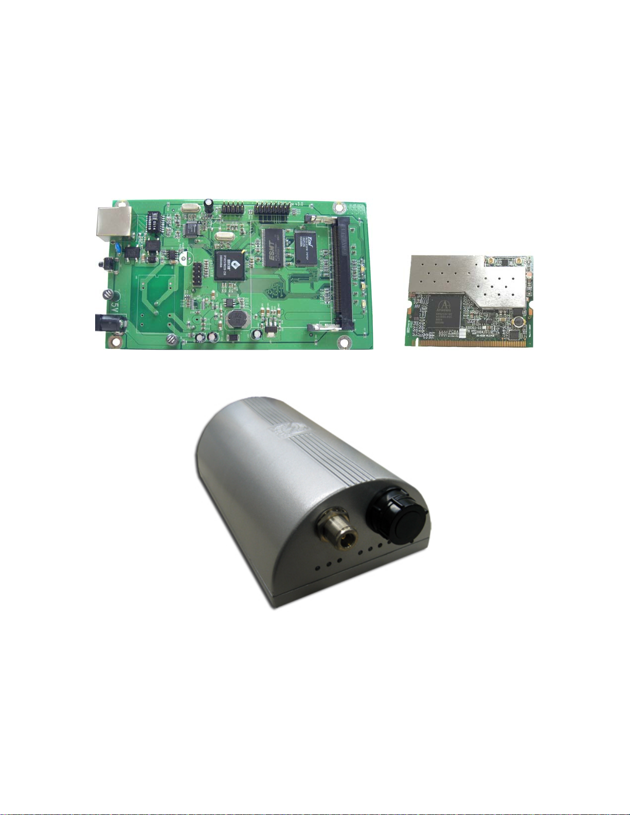
TT5800 Product Photos
TT5800 PCB
IEEE 802.11a miniPCI Card
TT5800 Enclosure (Cast Aluminum, Powder Coated Silver)
4

Product Features
• Compact size for small enterprise or system integrate service market
• Compliant with IEEE 802.11a specifications
• Supports 64/128-bit WEP, WPA and IEEE802.1x
• Supports Atheros Super A (up to 108Mbps)
• Intelligent firmware upgrade via Web browser
• Built-in Web-based utility for easy configuration from any Web browser
• Support POE (IEEE 802.3af) function
• Supports wireless bridging and MAC address filtering
• Super bright LED indicating status and signal level (RSSI)
• Provide 10/100M, auto sensing MDI/MDI-X Ethernet port
• EzManager Support
*Atheros Super G (Proprietary technology of Atheros Communication Inc.) would only work in situations where both
ends of the communication link are using the Athero s radi o chipset.
Product Specifications
Main Chips
• CPU: Ubicom IP3023
• Radio: Supports 802.11a Atheros AR5213+AR5112
Mechanical
• Chassis Dimension (W x D x L): 161mm x 30mm x 119mm
Board Specifications
Specification Description
Network Standard IEEE 802.11 a, IEEE 802.3, IEEE802.3x
Ethernet 10/100BaseT Ethernet, Auto MDI/MDI-X
Network Architecture Infrastructure; Ad-Hoc
MAC CSMA/CA
Status Indicators
Push Button Reset to Default Button
POWER, Wireless LAN(RF),Ethernet LAN, Receives Signal
Strength(RSS)
5

Radio Specifications
• IEEE 802.11a 5 GHz mini-PCI card
Specification Description
Chipset MAC/BB Processor Atheros AR5213 RF Chip Atheros AR5112
Power Consumption IEEE 802.11a TX: ~1000 mA RX: ~400 mA
Antenna Connector N-type Female
Output Power
Receiver Sensitivity
Modulation
Operating Frequency
• 16dBm (± 2dB) @ 54Mbps
• 17dBm (± 2dB) @ 48Mbps
• 18dBm (± 2dB) @ 36Mbps
• 19dBm (± 2dB) @ 6 Mbps
IEEE 802.11a Sensitivity @ 10% Packet Error Rate
• 54Mbps: -70dBm
• 48Mbps: -71dBm
• 36Mbps: -75dBm
• 24Mbps: -79dBm
• 18Mbps: -82dBm
• 12Mbps: -84dBm
• 9Mbps: -86dBm
• 6Mbps: -87dBm
IEEE 802.11a (OFDM)
• 48/54 Mbps (QAM-64)
• 24/36 Mbps (QAM-16)
• 12/18 Mbps (QPSK)
• 6/9 Mbps (BPSK)
• USA(FCC): 5.15GHz ~ 5.25GHz, 5.25GHz ~ 5.35GHz, 5.47
GHz ~ 5.725 GHz, 5.725 GHz ~ 5.825 GHz
• Europe(ETSI): 5.15 GHz ~ 5.35 GHz, 5.47 GHz ~ 5.725
GHz
• Japan(TELEC): 5.15 GHz ~ 5.25 GHz
• IEEE 802.11b/g 2.4 GHz mini-PCI card
Specification Description
Chipset MAC/BB Processor Atheros AR5213 RF Chip Atheros AR5112
Power Consumption
Antenna Connector U.Fl R-SMT (Inside), N-type Female (Outside)
Output Power
IEEE 802.11b TX: ~1500 mA RX: ~400 mA
IEEE 802.11g TX: ~1500 mA RX: ~400 mA
IEEE 802.11b:
• 22dBm (± 3dB) @ 1Mbps
• 22dBm (± 3dB) @ 2Mbps
• 22dBm (± 3dB) @ 5.5Mbps
6

• 22dBm (± 3dB) @ 11Mbps
IEEE 802.11g:
• 21dBm (±3dB) @ 54Mbps
• 22dBm (±3dB) @ 48Mbps
• 22dBm (±3dB) @ 36Mbps
• 22dBm (±3dB) @ 6 Mbps
IEEE 802.11b
Sensitivity @ 8% Packet Error Rate
IEEE 802.11g
Sensitivity @10% Packet Error Rate
Receiver Sensitivity
Modulation
Operating Frequency
• 54Mbps:-72dBm
• 48Mbps:-73dBm
• 36Mbps:-77dBm
• 24Mbps:-81dBm
• 18Mbps:-84dBm
• 12Mbps:-86dBm
• 9Mbps:-88dBm
• 6Mbps:-89dBm
• 11Mbps:-88dBm
• 5.5Mbps:-90dBm
• 2Mbps:-92dBm
• 1Mbps:-95dBm
• 11Mbps:-88dBm
• 5.5Mbps:-90dBm
• 2Mbps:-92dBm
• 1Mbps:-95dBm
IEEE 802.11b (DSSS)
• 5.5/11 Mbps (CCK)
• 2 Mbps (DQPSK)
• 1 Mbps (DBPSK)
IEEE 802.11g (OFDM/DSSS)
• 48/54 Mbps (QAM-64)
• 24/36 Mbps (QAM-16)
• 12/18 Mbps (QPSK)
• 6/9 Mbps (BPSK)
• 5.5/11Mbps (CCK)
• 2Mbps (DQPSK)
• 1Mbps (DBPSK)
• USA(FCC): 2.412GHz ~ 2.462 GHz (CH1 ~ CH11)
• Europe(ETSI): 2.412 GHz ~ 2.472 GHz (CH1 ~ CH13)
• Japan(TELEC) : 11b: 2.412 GHz ~ 2.484 GHz (CH1 ~ CH14)
11g: 2.412 GHz ~ 2.472 GHz (CH1 ~ CH13)
7

LED Definition
Item Specification
Power
RF(WLAN)
ON (Red) Power on
Off No power
On (Yellow) Connected
Off Not connected
Blinking(Green) Connected and transmitting
On (Green) Connected
LAN
Received Signal Strength
Indicator (RSSI)
Software Specification
Item Specification
Bridge Features
Security Features
Management Features
External AC Power Adapter
Item Specification
Input Voltage 110-240VAC
Line Frequency 50/60Hz
Power Output to M/B 48VDC, 1A
Off Not connected
Blinking(Green) Connected and transmitting
Blinking left to
right
On
• Universal Bridging
• MAC Address Cloning
• RTS Threshold/Fragmentation Threshold
• Infrastructure or Ad-Hoc Mode
• Non-IP Traffic Bridging
• 64-Bit/128-Bit WEP Encryption
• WPA Personal Using TKIP or AES
• WPA Enterprise Using TKIP or AES
• 802.1x Authenticator
• Cisco LEAP Support
• MAC Address Filter
• Web Access (Username/Password Protected)
• Static IP
• Automatic Device Discovery & Configuration
• SNMP v1, DHCP and PPPoE (Ethernet or Wireless)
• Firmware Upgrade via Web Browser
• Transmit Power Adjustment
Not connected (Scanning for AP)
Connected, indicating Received Signal
Strength.
8

Environmental
Item Specification
Operating Temperature
Storage Temperature
-20 C to 40 C (-4 F to 104 F),
10 to 90% (non-condensing)
-25 C to 70 C (-13 F to 158 F),
10 to 90% (non-condensing)
Standards / Regulatory Compliance
• CE, FCC
Product Kit Part Listing
1. TT5800 802.11a PCBA or TT2400 802.11b/g PCBA (1)
2. IEEE 802.11a o r IEEE 802.11b/g mini-PCI radio card (1)
3. Power over Ethernet Injector (1)
4. 48VDC Power Adapter (1)
5. Ethernet Cable (2)
6. Waterproof RJ-45 Connector (1)
7. Mounting Hardware (1)
8. User Manual
Note: If any item listed above is damaged or missing, please contact your dealer immediately.
System Requirements
• Any desktop or laptop with an Ethernet interface
• TCP/IP protocol suite installed
• Standard CAT5 Ethernet cables with RJ45 connectors
• Internet Explorer 5.0 or later / Firefox 1.0 or higher
9

Installation
Preparation for Installation
Always double check for any missing parts from the kit you received before deployment.
The next step is to set up the computer Ethernet interface for configuring the TT5800/TT2400. Since the default IP
Address of the unit is on the 192.168.10.x IP range in both Client Bridge and AP mode you will need to set the Ethernet
interface within the same IP range, where x will have to be a free IP address number from 1-254.
Check the following section - “Hardware Installation” and the next chapter - “Configuring Windows for IP Networking” to
obtain complete details.
Hardware Installation
Follow the procedure below to install your TT5800/TT2400 device:
1. Select a suitable place on the network to install the TT5800/TT2400. For best wireless reception and
performance the external antenna should be positioned within Line of Sight from the AP with proper alignment.
2. Connect the TT5800/TT2400 to the ODU side of the PoE Injector, via a straight Ethernet cable (Cat-5), and then
connect the NET side of the PoE Injector to either a computer or an Ethernet Switch. Note: The TT5800/TT2400
now fully supports the MDI/MDI-X standard and no longer requires the use of a cross over cable to connect
directly with a computer.
3. Connect the 48VDC power adapter to the power jack on the PoE injector to power on the TT5800/TT2400.
4. Check the LEDs on the TT5800/TT2400 to confirm if the status is okay. At this point the Power (PWR) LED
indicator should be red and Ethernet (LAN) LED should be green. The RF light should light up once the unit is
associated wirelessly with another wireless device. However at this point the unit is still in factory default setting
so do not be alarmed that the WLAN light doesn’t light up.
5. Now the hardware installation is complete and you may proceed to the next chapter –“Configuring Windows for
IP Networking” for instructions on setting up network configurations.
10

Configuring Windows for IP Networking
To establish a communication link between your PC and TT5800/TT2400, you will need to set up a static IP address
for your computer first. This section helps you configure the network settings for your operating system. Please follow
the procedures below to complete the settings:
Windows XP
1. Click Start on the taskbar and from the Control Panel choose Network Connections. Right-click the Local
Area Connection icon and then choose Properties from the menu. You should see the Local Area Connection
Properties dialog box shown below.
2. Select the Internet Protocol (TCP/IP) for your network card, and then click Properties.
3. In the opened dialog box, choose Use the following IP address
4. Under the General tab, choose Use the following IP address, and then specify an IP address. For example,
type in 192.168.10.X in the IP Address (where X is any free IP number from 1-254, excluding 241) area and
255.255.255.0 in the Subnet Mask area.
11
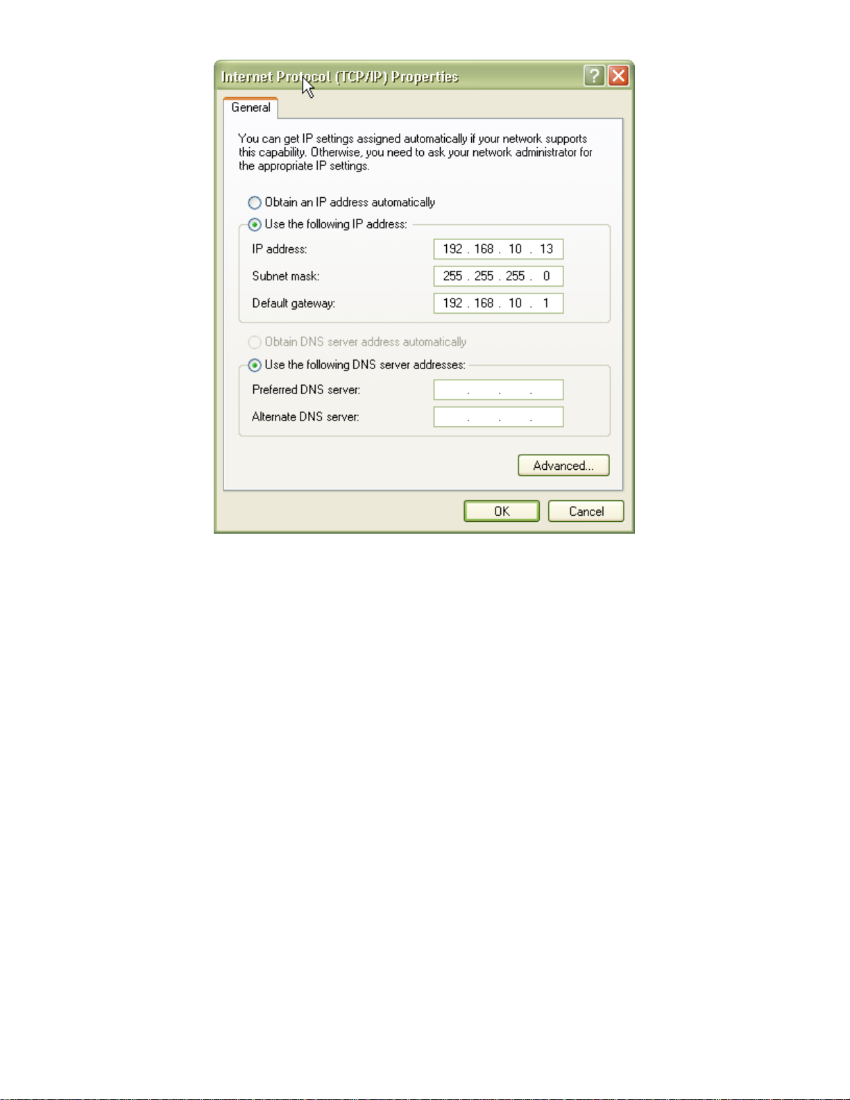
5. Click OK to finish configuration.
12
Web Configuration Interface
Client Bridge Mode
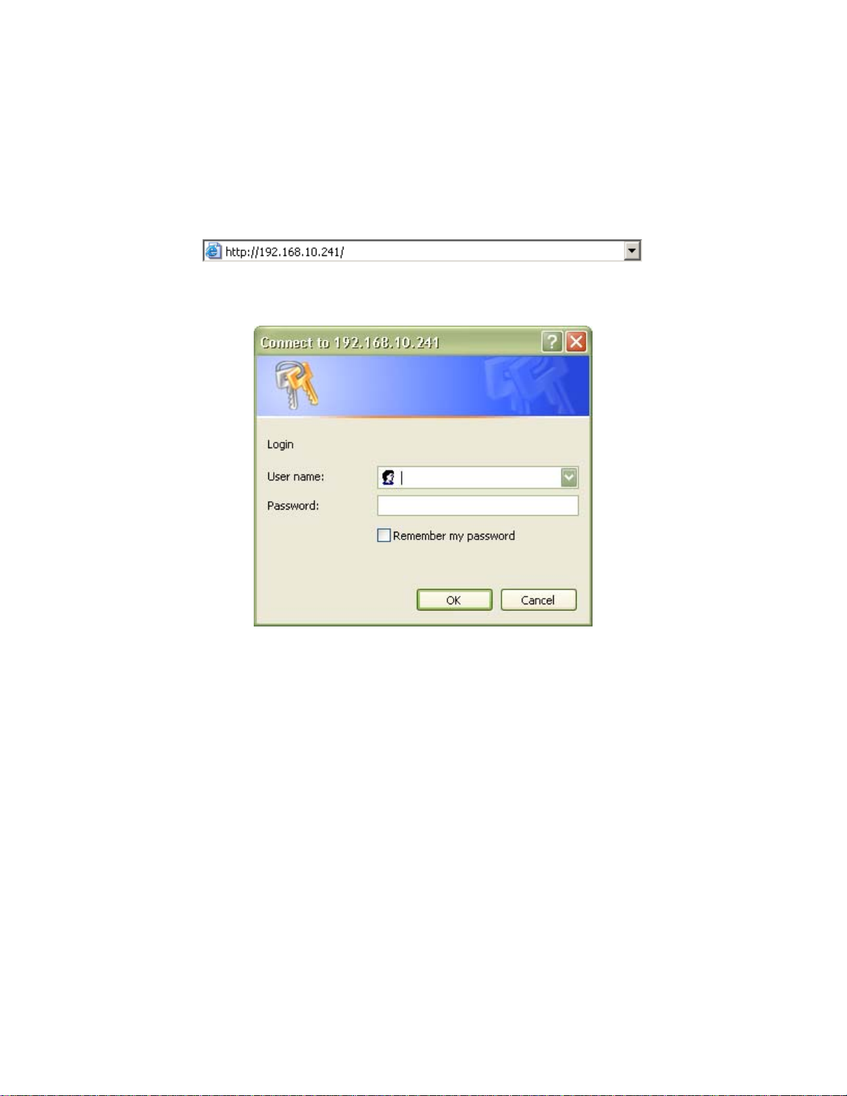
Default IP Address in Client Bridge Mode: 192.168.10.241
To access the web control interface please open up a browser window and type in the factory default IP address in the
URL.
Press Enter on your keyboard and a login prompt window similar to the one shown below will appear.
There is no default User name or Password. Leave User name and Password field blank and click OK.
Note: You may set a new password by clicking the Admin tab after you enter the Web Configuration page.
13
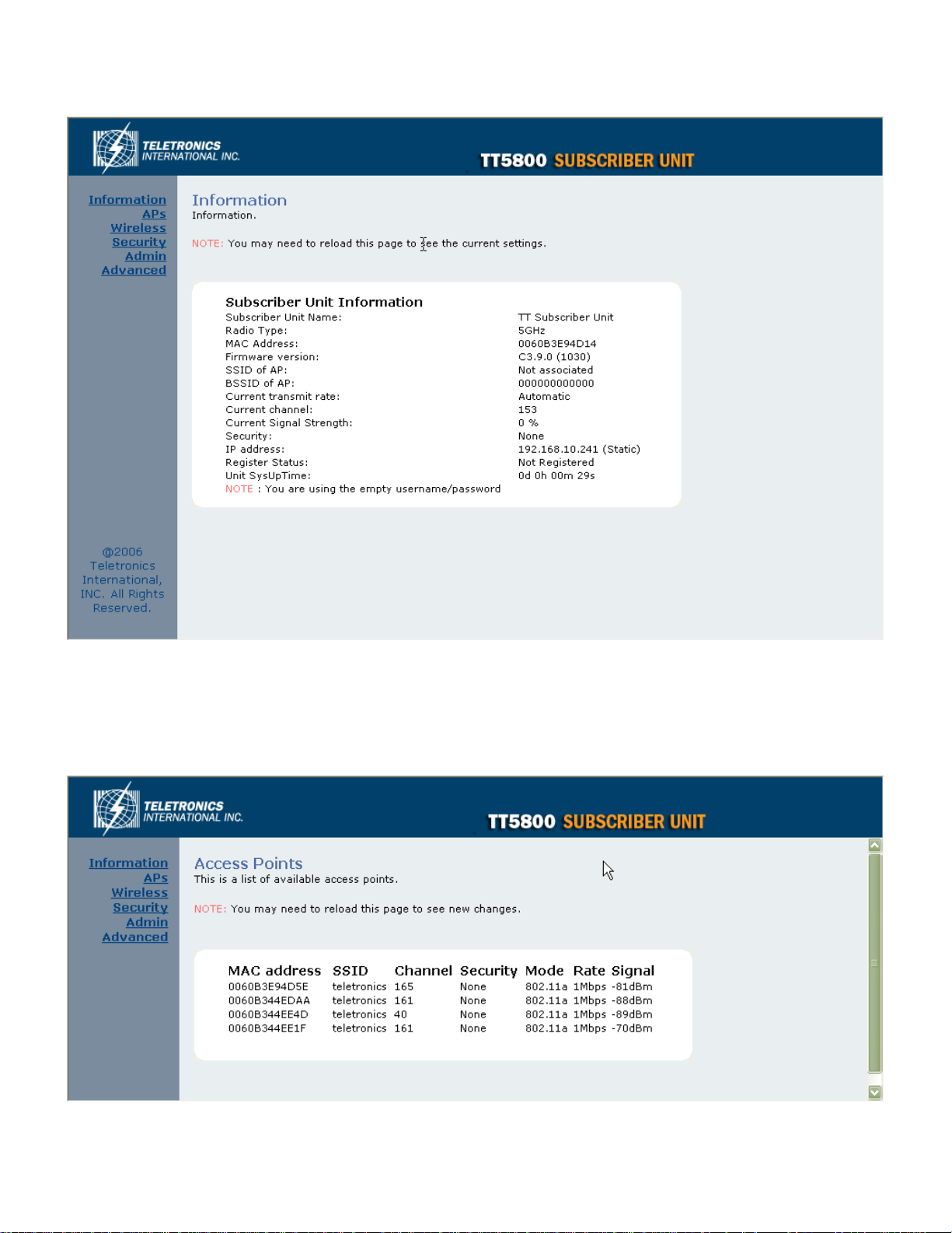
Information
Under the main web interface home page you will see the following configuration menu pages: Information, APs,
Wireless, Security, Admin and Advanced. Detailed information for each section is provided below:
Access Points (APs)
The APs section displays available hotspots in the area along with the MAC address, SSID, Channel, Wireless mode,
signal strength and transmission rate for each access point.
14
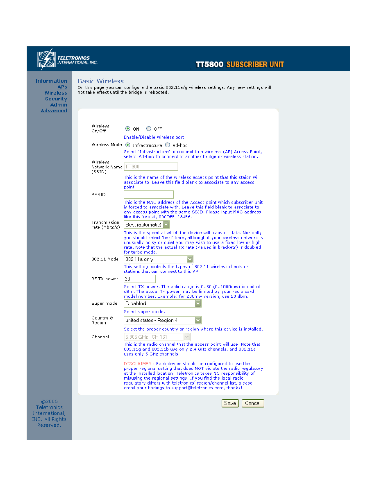
Wireless
15

Wireless On/Off
This is the on/off switch of the radio card.
Wireless Mode
Infrastructure: An 802.11 networking framework in which devices communicate with each other by first going through
an Access Point (AP).
Ad-hoc: An 802.11 networking framework in which devices or stations communicate directly with each other, without
the use of an access point (AP). Use this mode if there is no wireless infrastructure or where services are not required.
Wireless Network Name (SSID)
Network Name is also known as SSID, which stands for Service Set Identifier. Any client in Infrastructure mode has to
indicate the SSID of an Access Point to access a service such as internet access through the Access point.
Access Point Identifier (BSSID)
The Basic Service Set Identifier is the unique identifier (MAC address) of an access point in a Basic Service Set (BSS)
network. The subscriber unit is forced to associate with this particular unit if there are multiple access points in the
network.
Transmission rate (Mbits/s)
This option indicates the transmission rate of the bridge. Specify the rate according to the speed of your wireless
network from the list. Most of the time the default setting, Best (automatic), should be selected for best performance.
The setting can be adjusted manually if the link quality and signal strength are unusually low or high to get the best
performance.
802.11 Mode
Wireless mode allows the user to select whether this subscriber unit will connect to an 802.11b only network, an
802.11g only network, an 802.11a only network or both b/g networks. For b or g only wireless devices on the network,
selecting 802.11b or 802.11g only mode will provide better performance than mixed mode. In the case of TT5800 only
802.11a mode is allowed. For TT2400 the options of 802.11b, 802.11g only or Mixed 802.11g and 802.11b are
available.
RF Transmit Power
This section controls the power output for the mini-PCI radio card. The valid input range for this section is in the range
of 0-30 in dBm units or (1mw – 1000mw). The default value is 23 dBm or 200mW.
Super Mode
Super Mode is only supported if both the client and the AP are using compatible Atheros radio chipsets
• Disabled
• Super A/G without Turbo
• Super A/G with Static Turbo
• Super A/G with Dynamic Turbo (AR enabled)
16

Country and Region
This option selects the country and region of operation. Every device should be configured to use the proper regional
settings which comply with and do NOT violate the radio regulatory laws at the installed location.
Channel
Channels are important to understand because they affect the overall capacity of your Wireless LAN. A channel
represents a narrow band of radio frequency. A radio frequency modulates within a band of frequencies; as a result
there is a limited amount of bandwidth within any given range to carry data. It is important that the frequencies do not
overlap or else the throughput would be significantly reduced as the network sorts and reassembles the data packets
sent over the air.
For the TT2400: 2.4 GHz – 2.497 GHz frequency range, there are only 3 channels out of the 11 available that do not
overlap with one another. To avoid interference within a network with multiple APs, set each AP to use one of the 3
channels (e.g. Channel 1) and then the other AP to be one of the other 2 channels (i.e. Channel 6 or Channel 11)
within the range of the wireless radio. This simple method will reduce interference and improve network reliability.
802.11b/g Wireless Channel Frequency Range: 2.4 GHz – 2.497 GHz
802.11b/g Non-overlapping Channel Frequency Ranges
• Channel 1 = 2.401 GHz – 2.423 GHz
• Channel 6 = 2.426 GHz – 2.448 GHz
• Channel 11 = 2.451 GHz – 2.473 GHz
Americas: Wireless Channels 1 – 11
Asia: Wireless Channels 1 – 14
Europe: Wireless Channels 1 – 13
802.11a Wireless Channel Frequency Range: 5.15 GHz – 5.35 GHz, 5.725 – 5.825
802.11a is an extension to 802.11 that applies to wireless LANs and provides up to 54 Mbps in the 5GHz band.
802.11a uses an orthogonal frequency division multiplexing encoding scheme rather than FHSS or DSSS. Unlike that
of 802.11b/g, 802.11a standard separates its channels into 3-100MHz segments in the US.
The lower and middle band accommodates 8 channels in a total bandwidth of 200 MHz and the upper band
accommodates 4 channels in a 100 MHz bandwidth. The frequency channel center frequencies are spaced 20 MHz
apart. The outermost channels of the lower and middle bands are centered 30 MHz from the outer edges. In the upper
band the outermost channel centers are 20 MHz from the outer edges.
In addition to the frequency and channel allocations, transmit power is a key parameter regulated in the 5 GHz U-NII
band. Three transmit power levels are specified: 40 mW, 200 mW and 800 mW. The upper band defines RF transmit
power levels suitable for bridging applications while the lower band specifies a transmit power level suitable for shortrange indoor home and small office environments.
802.11a Non-overlapping Channel Frequency Ranges
Lower Band (5.15 - 5.25 GHz) – Maximum Output Power 40mW
• Channel 36 = 5.15 – 5.18
• Channel 40 = 5.18 – 5.20
• Channel 44 = 5.20 – 5.22
• Channel 48 = 5.22 – 5.25
Middle Band (5.25 - 5.35 GHz) – Maximum Output Power 200mW
• Channel 52 = 5.25 – 5.28
• Channel 56 = 5.28 – 5.30
• Channel 60 = 5.30 – 5.32
• Channel 64 = 5.32 – 5.35
17

Upper Band (5.725 - 5.825 GHz) – Maximum Output Power 800mW
• Channel 149 = 5.725 – 5.745
• Channel 153 = 5.745 – 5.765
• Channel 157 = 5.765 – 5.785
• Channel 161 = 5.785 – 5.805
• Channel 165 = 5.805 – 5.825
Special Atheros Turbo Mode Channels
*Use this setting only when both side of the wireless connection is using the Atheros chipset. The radio will combine 2
free channels for the wireless transmission to double the bandwidth.
• Channel 42 = 5.210
• Channel 50 = 5.250
• Channel 58 = 5.290
• Channel 152 = 5.760
• Channel 160 = 5.800
18
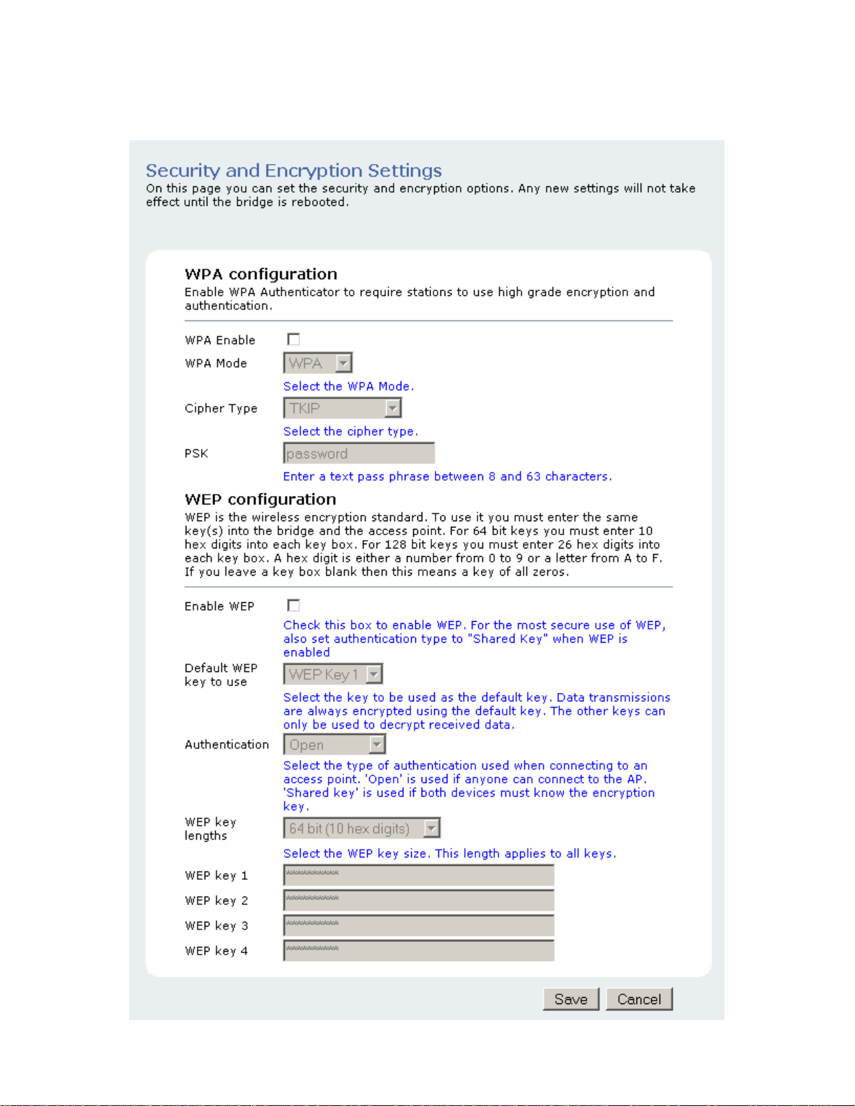
Security
19

WPA Configuration
Short for Wi-Fi Protected Access, WPA is a Wi-Fi standard that was designed to improve upon the security features of
WEP. WPA has the following improvements over WEP:
• Improved data encryption through temporal key integrity protocol (TKIP). TKIP scrambles the keys using a
hashing algorithm. By adding an integrity-checking feature, TKIP ensures that keys have not been tampered
with.
• User authentication through the Extensible Authentication Protocol (EAP). WEP regulates access to a wireless
network based on a computer’s hardware-specific MAC address, which is relatively simple to be sniffed out
and stolen. EAP is built on a more secure public-key encryption system to ensure that only authorized network
users can access the network.
WPA Enable
This option enables the WPA Authenticator. Note that any client that does not support the WPA standard will not be
able to handshake / authenticate with a WPA enabled device.
WPA Mode
• WPA
• WPA2
o Designed to secure present and future versions of IEEE 802.11 devices, WPA is a subset of the IEEE
802.11i specification. WPA addresses all known vulnerabilities in WEP. WPA also provides user
authentication, since WEP lacks any means of authentication. WPA replaces WEP with a strong new
encryption technology called Temporal Key Integrity Protocol (TKIP) with Message Integrity Check
(MIC). It also provides a scheme of mutual authentication using IEEE 802.1X/Extensible
Authentication Protocol (EAP) authentication or pre-shared key (PSK) technology. WPA was designed
and has been scrutinized by well-known cryptographers. It can be implemented immediately and
inexpensively as a software or firmware upgrade to most existing Wi-Fi CERTIFIED™ access points
and client devices with minimal degradation in network performance. WPA offers standards-based, WiFi CERTIFIED security. It assures users that the Wi-Fi CERTIFIED devices they buy will be crossvendor compatible. When properly installed, WPA provides a high level of assurance to enterprises,
small businesses and home users that data will remain protected and that only authorized users may
access their networks. For enterprises that have already deployed IEEE 802.1X authentication, WPA
offers the advantage of leveraging existing authentication databases and infrastructure.
o WPA2 is the second generation of WPA security; providing enterprise and consumer Wi-Fi® users with
a high level of assurance that only authorized users can access their wireless networks. Launched in
September 2004 by the Wi-Fi Alliance, WPA2 is the certified interoperable version of the full IEEE
802.11i specification which was ratified in June 2004. Like WPA, WPA2 supports IEEE 802.1X/EAP
authentication or PSK technology. It also includes a new advanced encryption mechanism using the
Counter-Mode/CBC-MAC Protocol (CCMP) called the Advanced Encryption Standard (AES). AES
satisfies U.S. government security requirements. It has been adopted as an official government
standard by the U.S. Department of Commerce and the National Institute of Standards and
Technology (NIST). Organizations that require the AES encryption available in WPA2 should be aware
that upgrading to it may require new hardware. Section II of this document offers a roadmap for
organizations planning to upgrade to WPA2. Considerations for its deployment are outlined in Section
III.
20
 Loading...