

Teletronics International EzBridge, EzBridge 802.11g WLAN Access Point User Manual

2
Table of Contents
Introduction - 4
1.1 Features - 4
1.2 Specifications - 4
1.3 Product Kit - 6
1.4 System Requirements - 6
The 802.11g EzBridge - 7
2.1 Ports - 7
2.2 LEDs - 7
2.3 Installation - 9
Configuring Windows for IP Networking - 10
3.1 If you are using Windows 98/Me - 10
3.2 If you are using Windows 2000 - 11
3.3 If you are using Windows XP - 13
Utilizing the Web Configuration Interface - 16
Station Bridge Mode - 16
4.1 Web Configuration Interface - 17
4.2 The Info Page - 18
4.3 The Configuration Page - 19
4.4 The Encryption Page - 22
4.5 The Advanced Page - 27
4.6 The Admin Page - 30

3
Access Point Mode - 33
5.1 Web Configuration Interface - 34
5.2 The Info Page - 34
5.3 The Assoc Page - 35
5.4 The Admin Page - 36
5.5 The Wireless Page - 37
5.6 The Access Page - 39
5.7 The Advanced Page - 40
5.8 The Security Page - 43
5.9 The IP Addr Tab - 46
5.10 The WDS Tab - 48
Appendix A - Warranty Policy - 49
Appendix B - RMA Policy - 50
Appendix C - Regulatory Information - 51
Appendix D - Contact Information - 54
Appendix E - Troubleshooting - 55
Appendix F - Glossary - 56

4
Introduction
The 802.11g WLAN Access Point card aims to assist you in easily building
a communicable connection between your wired LAN and one or more
Wireless Local Area Networks. It’s easy to install and operate. To let you
enjoy the most advantages of this product, please read this manual
carefully.
1.1 Features
• 802.11b and 802.11g standards compliant
• Quick and easy to install
• Works with any device that has an Ethernet port
• LED indicators show unit operating status
• FCC Certified for use with YDI amplifiers and outdoor antennas with
the Diamond WLAN Card
• Web-based configuration screen of Access Point enables fast and easy
setup
• Supports RTS threshold control for better throughput
• Wireless data encryption with 64 and 128 bits encryption for security
• One-year warranty
1.2 Specifications
Network Standard: 802.11b or 802.11g
Operating Channels: 11 channels (US, Canada)
Data Rate: Up to 54Mbps
LEDs: LAN, WLAN, Power
Transmit Power: 17 +/- 1dBm (802.11b CCK); 14 +/- 1dBm (802.11g
OFDM)

5
Receiver Sensitivity: 11 Mbps: -86dBm (802.11b); 54 Mpbs: -69dBm
(802.11g)
Modulation: CCK, DQPSK, DBPSK (802.11b), BPSK, QPSK, 16QAM,
64QAM (802.11g)
Spreading: DSSS (802.11b), OFDM (802.11g)
Network Protocols: TCP/IP, NetBEUI
Mini PCI Card Antenna Connector: U.FL Connector
(Use connector near the center for external Antenna installation)
Ethernet Port: 100 BaseT Ethernet
Security Filter: MAC Address Filtering for 8 clients
Regulatory Approval: FCC 47CFR15 subpart C (15.247) and Class B
device ETSI 300-3328/301-489-17 (General EMC requirement for RF
equipment)
Weight PCB: 6.87 oz (195g)
Dimensions PCB: 6.3" x 1.2" x 4.7" (161mm x 30mm x 119mm)
Weight w/ NEMA4 Box: 2.5 lb (1.13 Kg)
Dimensions w/ NEMA4 Box: 7" L x 5.4" W x 2.8" H (18cm L x 13.8cm W x
7.3cm H)
Environmental:
Operating Temperature: -4°F to 158°F (-20°C to 70°C)
Humidity: 10 to 90% (non-condensing)
AC Adapter:
Input 120 VAC -- 60 Hz -- 10 W
Output 9 VDC -- 1.5 A

6
1.3 Product Kit
The EzBridge Kit contains the following items:
¸ EZBridge 802.11g Unit
¸ Power over Ethernet Injector
¸ AC/DC Power Adapter
¸ Ethernet Cable
¸ Ethernet Crossover Cable
¸ Waterproof RJ-45 Connector
¸ Mounting Hardware
¸ User Manual
Note: If any item listed above is damaged or missing, please contact your
dealer immediately.
1.4 System Requirements
To accomplish a successful operation of your 802.11g WLAN Access Point,
we suggest the following items are required:
¸ One or more PCs (desktop or notebook) with Ethernet interface.
¸ TCP/IP protocol must be installed on all PCs.
¸ Network cables. Use standard 10/100BaseT network (UTP) cables
with RJ45 connectors.
¸ To use the Wireless Access Point, all wireless devices must be
compliant with the IEEE 802.11g specifications.
¸ Microsoft Internet Explorer 5.0 or later or Netscape Navigator 4.7 or
later.
7
The 802.11g EzBridge
This section is consisted of three parts. You will learn the guise of the
hardware, including the ports and LEDs, and the installation of Access
Point.
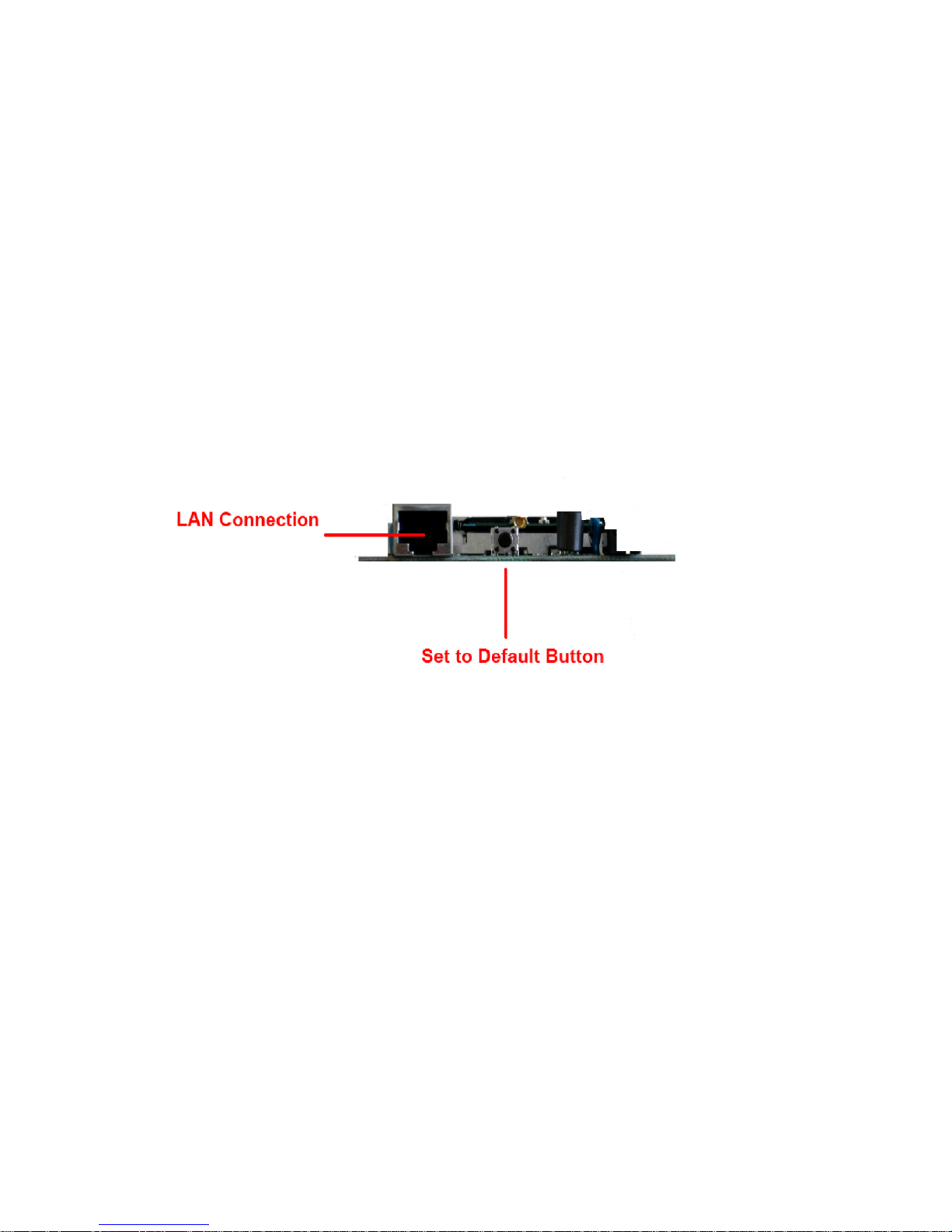
2.1 Ports
The ports are on the rear panel of the device. Please see the following
picture – the rear view of the Access Point to learn more details about your
device.
LAN Connection Use Ethernet straight LAN cable to connect your
PC, hub/switch or broadband router/modem to this
port.
Set to Default Button When you press this button, the Access Point will
reboot and reset current settings to factory default
settings.
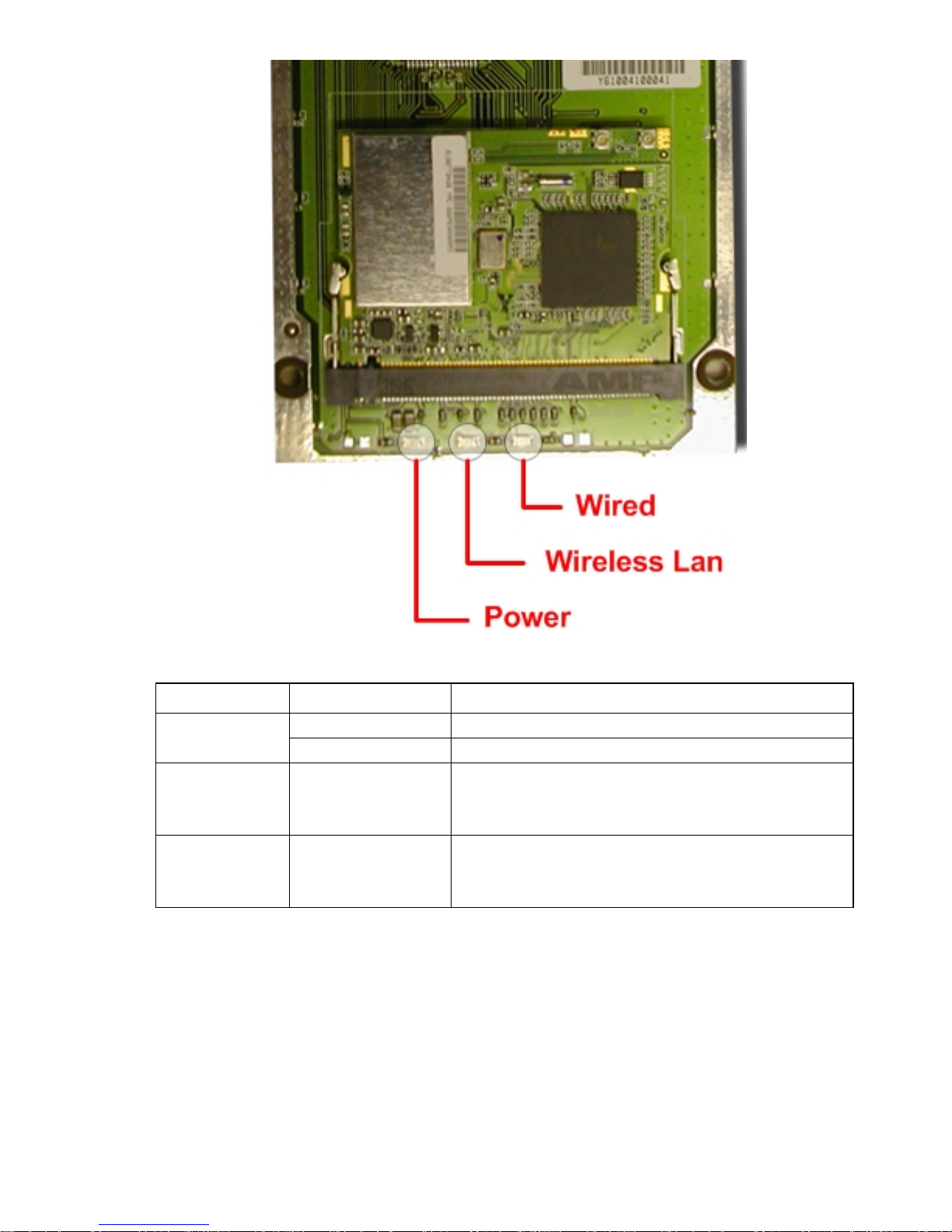
2.2 LEDs
The 802.11g WLAN Access Point includes three types of LED indicators.
Please check the following picture – the front view of the Access Point and
table to obtain the information on the LED indicators on your Access Point.
8
LED
Status
Function
On
Power on.
Power
Off
No power.
Wireless LAN
Blinking
On
Off
Blinking: Wireless LAN is transmitting.
On: Wireless LAN connection is active.
Off: Wireless LAN connection is not active.
Wired
Blinking
On
Off
Blinking: Wired LAN is transmitting.
On: Wired LAN is active.
Off: Wired LAN is not active.

9
2.3 Installation
Preparation for Installation
Before you actually install your 802.11g WLAN Access Point, please ensure
that all the items listed in “1.4 System Requirements” are prepared, and
then choose the place with the consideration of power outlet and network
connection to install the Access Point.
To avoid causing any damage to the Access Point hardware device, please
do not power up the device before you start to connect it to the port on your
PC.
Also notice that a full installation of your Access Point includes not only the
hardware installation but also the network configuration on your PC. Check
the following section -“Hardware Installation” and the next chapter “Configuring Windows for IP Networking” to obtain complete details.
Hardware Installation
Follow the procedures below to fully install your Access Point hardware
device:
1. Select a suitable place on the network to install the Access Point.
Ensure the Access Point and the DSL/cable modem are powered off.
For best wireless reception and performance, the Access Point should
be positioned in a central location with minimum obstructions between
the Access Point and the PCs.
2. Connect one end of Ethernet cable to Access Point and the other to
switch or hub, and then the Access Point will be connected to the
10/100 Network.
3. Connect the power adapter to the power socket on your Access Point.
4. Last but not the least, check the LEDs on the Access Point to confirm
if the status is okay.
5. Now the hardware installation is complete, and you may proceed to
the next chapter –“Configuring Windows for IP Networking” for
instruction on setting up network configurations.
10
Configuring Windows for IP Networking
To establish a communication between your PCs and the 802.11g WLAN
Access Point, you will need an IP address for your computer first. This
section helps you configure the network settings for your operating system.
Please follow the procedures below to complete the settings:
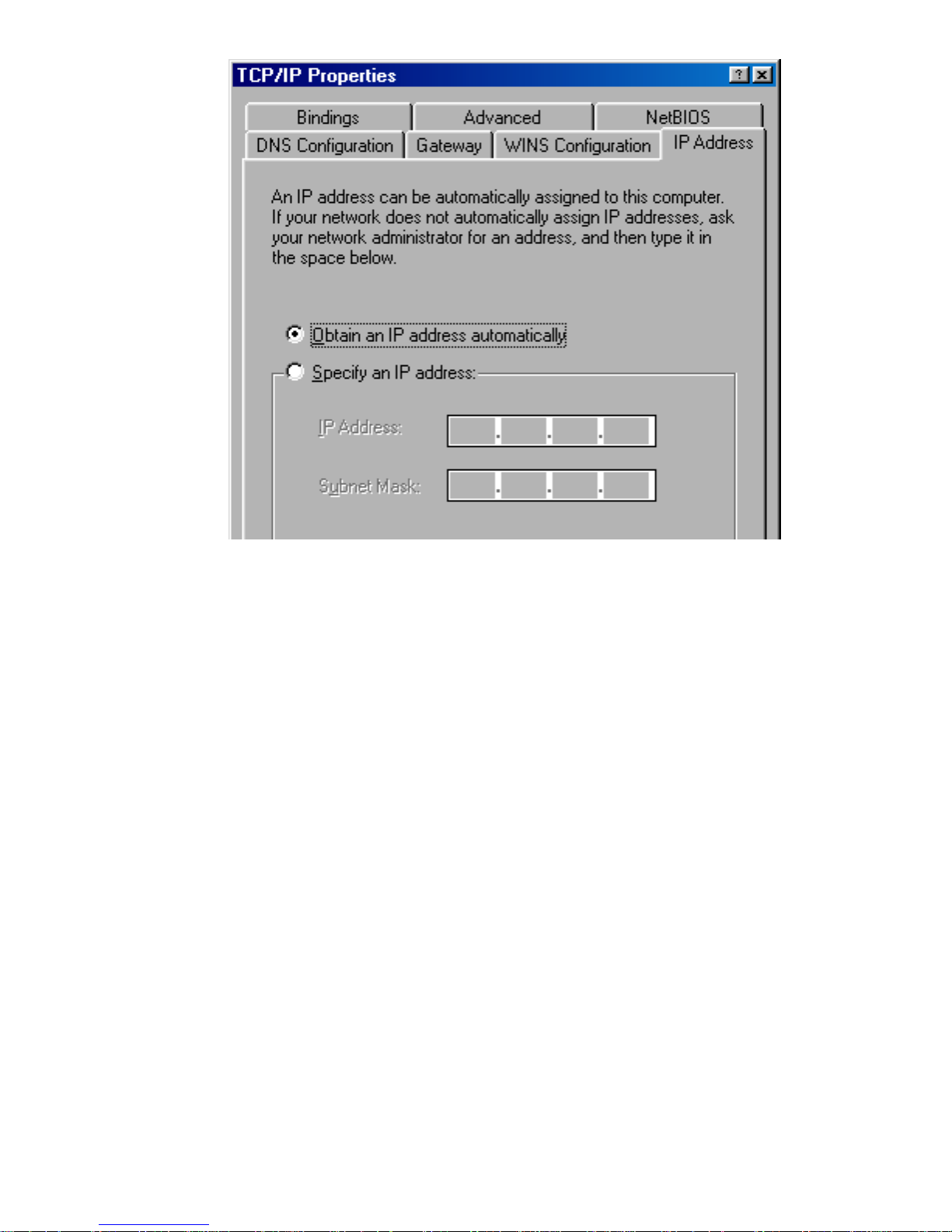
3.1 If you are using Windows 98/Me:
1. Click Start on the taskbar and choose Control Panel from the
submenu of Settings.
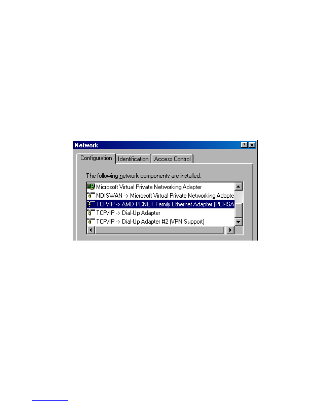
2. Select Network to open the Network dialog box, and then under the
Configuration tab, select the TCP/IP protocol for your network card.
3. Click Properties to open the TCP/IP Properties dialog box.
4. Click the IP Address tab and choose Specify an IP address. For
example, type 192.168.1.200 in the IP Address area and
255.255.255.0 in the Subnet Mask area. To ensure the system is
now using the IP address you specify, restart your computer to check
later.
11
Note: The IP address must be 192.168.1.x. The value of X should be
ranged from 1 to 254 and is never used by other PCs.
5. Click OK, and then restart the system.
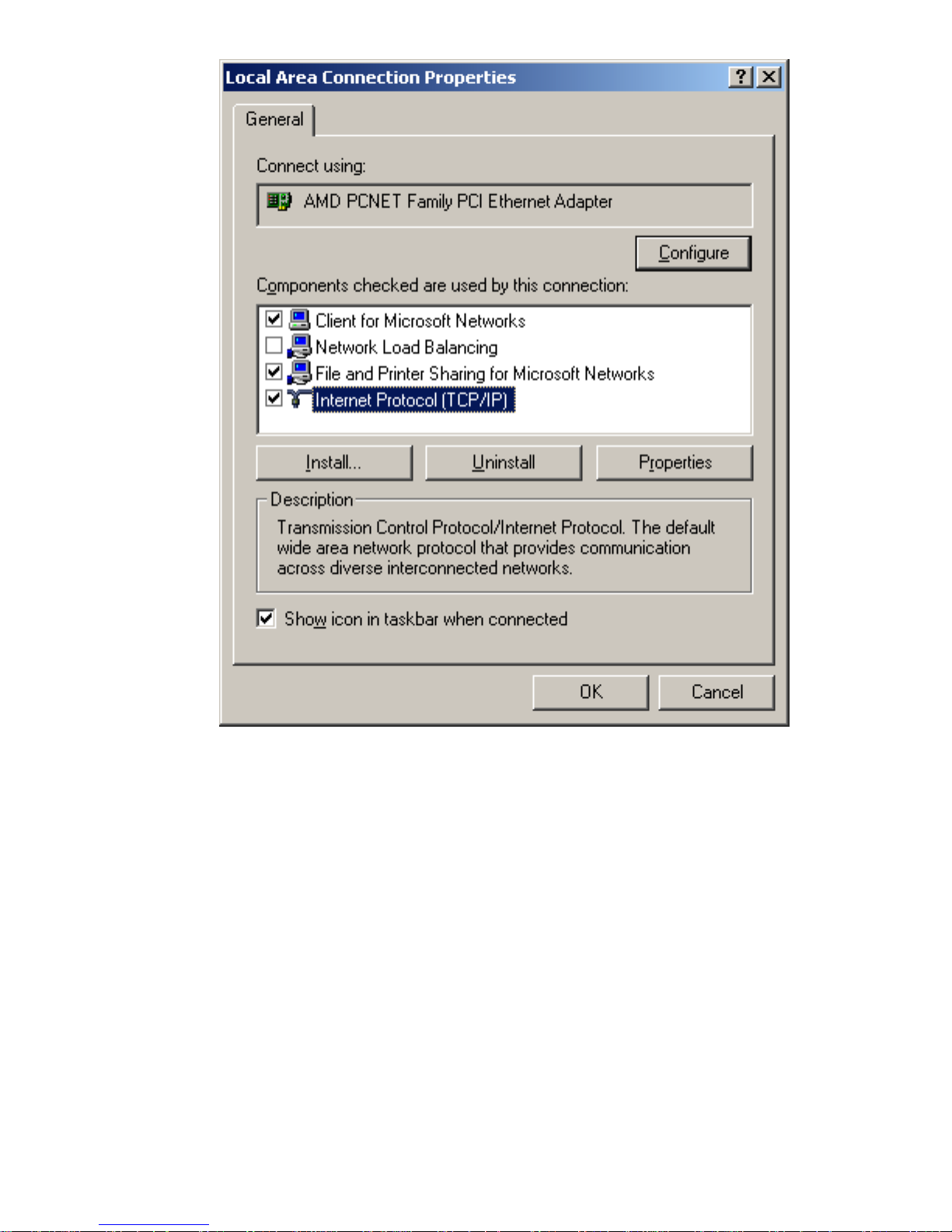
3.2 If you are using Windows 2000:
1. Click Start on the taskbar and choose Network and Dial-up
Connection from the submenu of Settings.
2. Double-click the Local Area Connection open the Local Area
Connection Properties box.
12
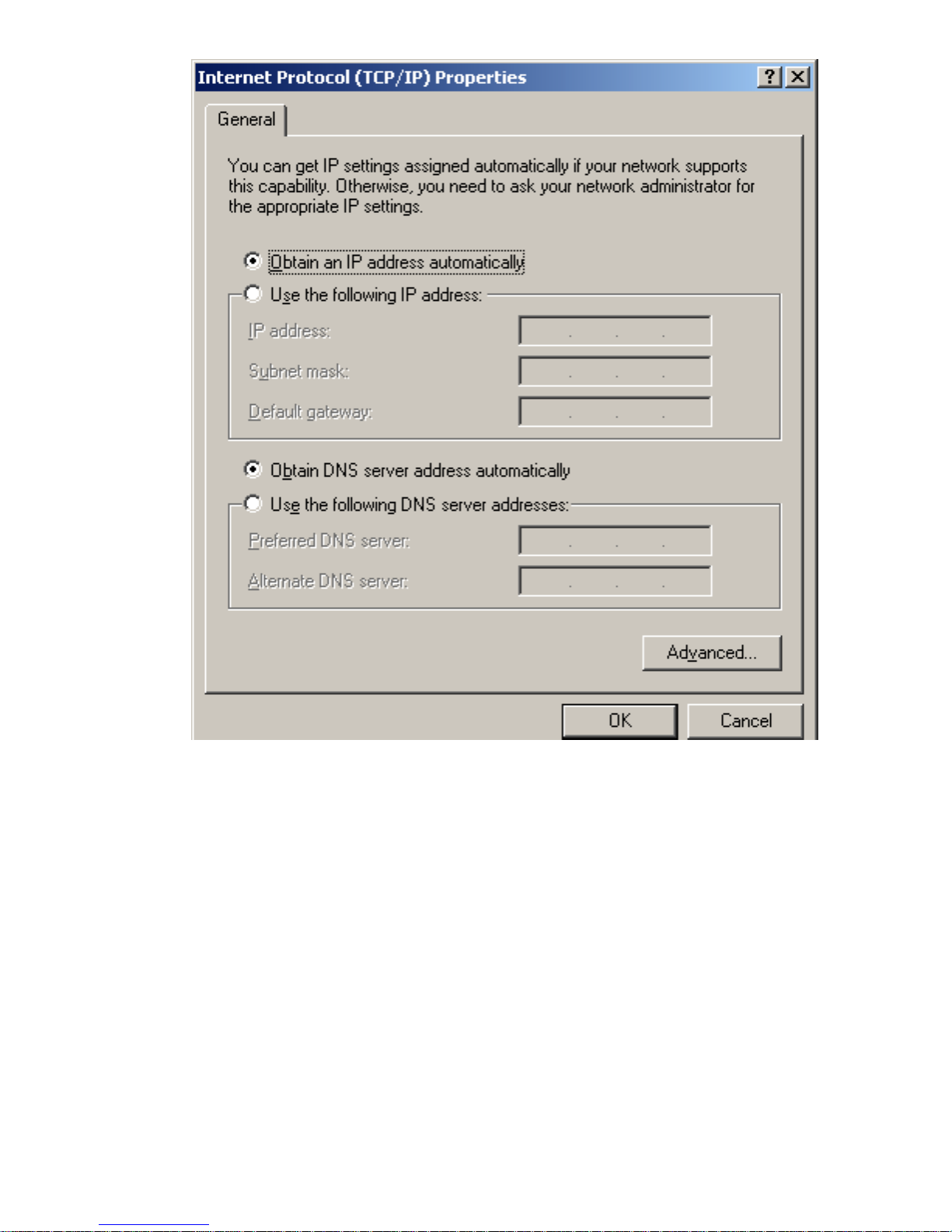
3. Select the Internet Protocol (TCP/IP) for your network card, and then
click Properties to open the Internet Protocol (TCP/IP) Properties
dialog box.
4. Under the General tab, choose Use the following IP address, and
then, for example, enter 192.168.1.200 in the IP Address area and
255.255.255.0 in the Subnet Mask area.
13
Note: The IP address must be 192.168.1.x. The value of X should be
ranged from 1 to 254 and is never used by other PCs.
5. Click OK, and then restart the system.
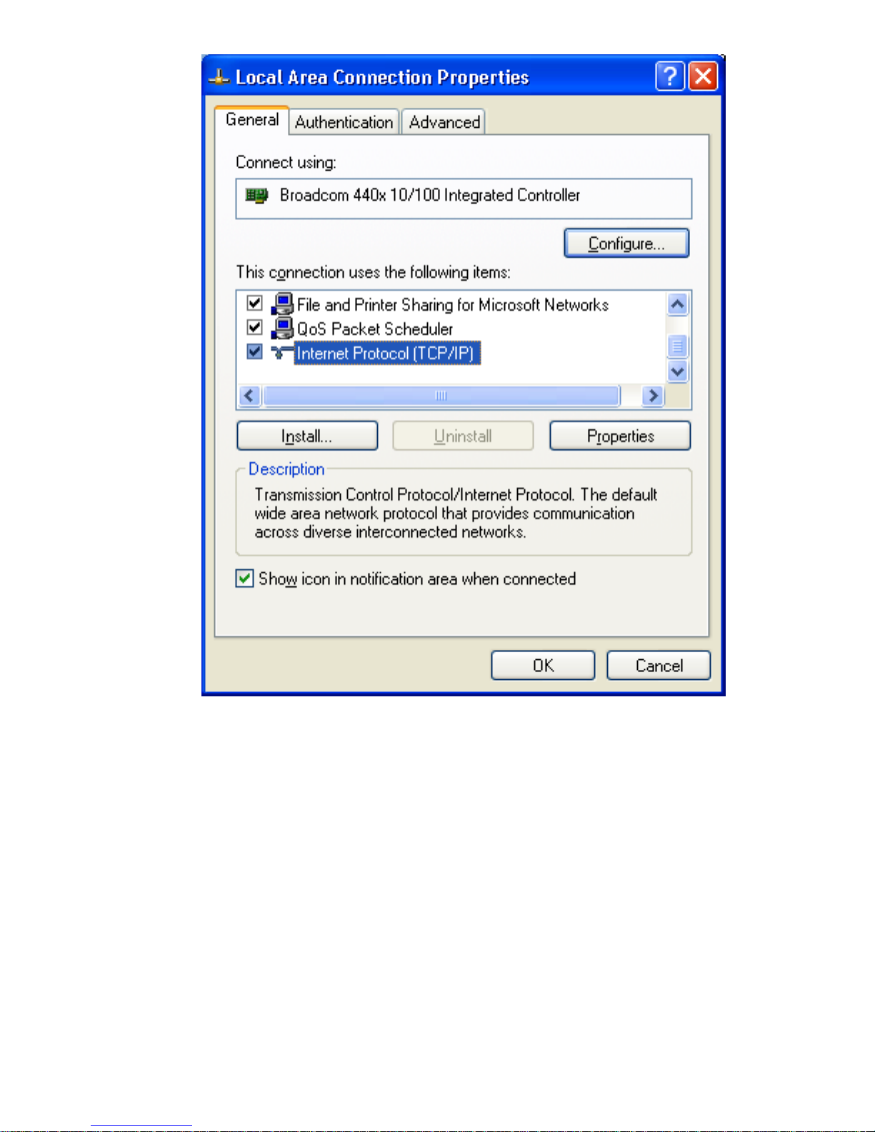
3.3 If you are using Windows XP:
1. Click Start on the taskbar and choose Network from the submenu of
Control Panel.
2. Right-click the Local Area Connection icon and then choose
Properties from the menu. You should see the Local Area
Connection Properties dialog box shown below.
14
3. Select the Internet Protocol (TCP/IP) for your network card, and then
click Properties.
4. In the opened dialog box, choose Use the following IP address
under the General tab, enter, for example, 192.168.1.200 in the IP
Address area and 255.255.255.0 in the Subnet Mask area.

15
Note: The IP address must be 192.168.1.x. The value of X should be
ranged from 1 to 254 and is never used by other PCs.
5. Click OK, and then restart the system.
16
Utilizing the Web Configuration Interface
Station Bridge Mode
The Access Point’s Web-based Configuration utility presents a user-friendly
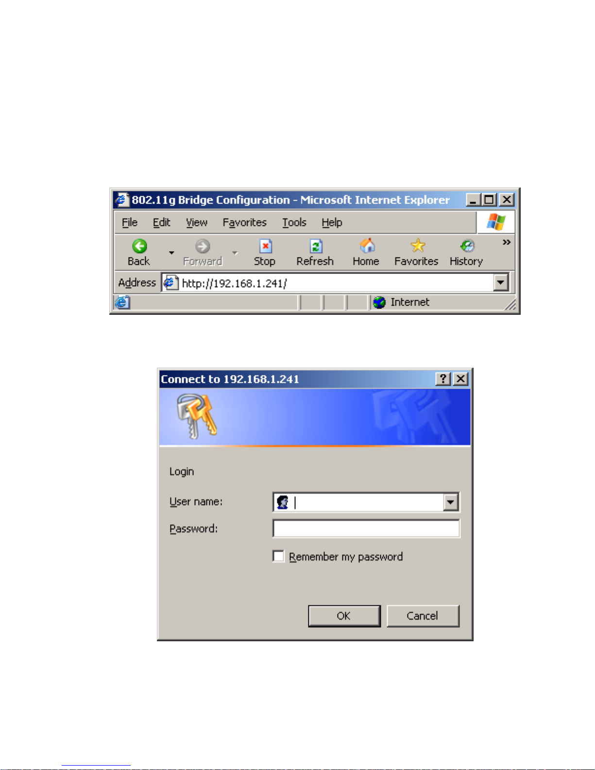
interface, so that you can easily execute the program by following the onscreen explanations. Type HTTP://192.168.1.241 in the Address box after
opening your Web browser.
Then press Enter on your keyboard, you will see the Enter Network
Password dialog box appear like the picture below shows.
The default User Name and Password is nil. Leave User Name and
Password field blank and then click OK.

17
Note: You may set a new password by clicking the Admin tab after you
enter the Web Configuration page
.
4.1 Web Configuration Interface
Under the main web interface page you will see the following configuration
menu pages:
Info, Configuration, Encryption, Advanced, Admin, and Help. Check the
sections below for detail information on the contents of each menu
interface.
18
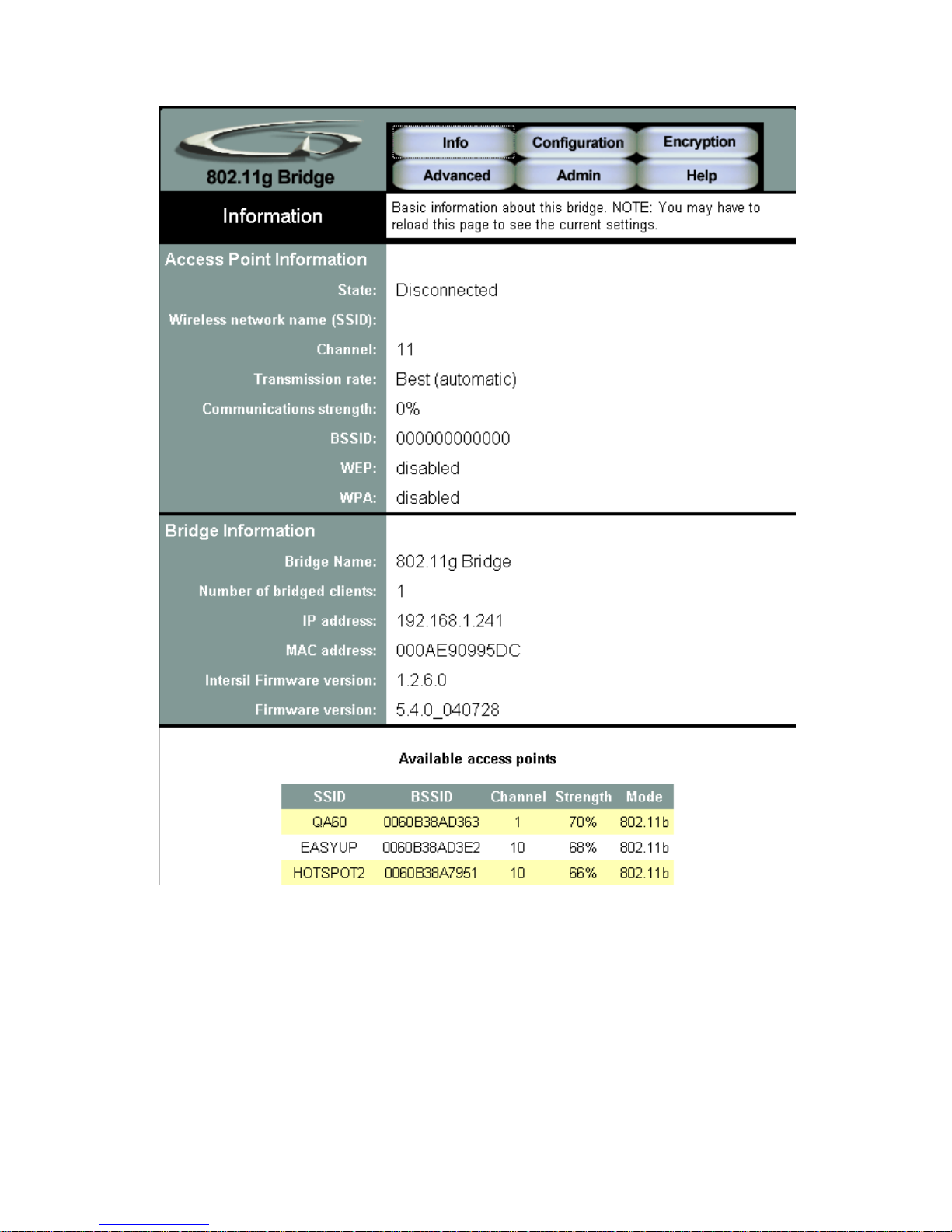
4.2 Info Page
Access Point Information
This section provides the basic access point information in which this unit is
associated with in bridge mode.
Bridge Information
19
This section provides the basic bridge setting information.
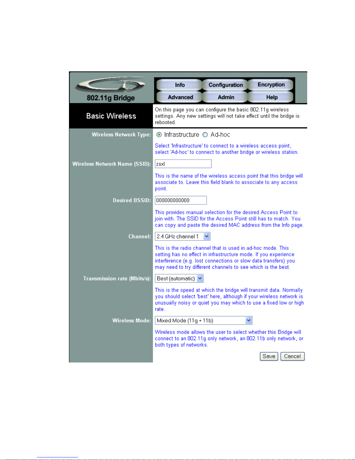
4.3 Configuration Page
 Loading...