

Page 1

W
W
L--
L
C
P
P
E--
E
C
Wireless Customer Premises Router
R
R
O
O
U
U
T
T
E
E
USER MANUAL
CPE Firmware v2.16
R
R
Page 2

Teletronics International Inc. CPE Complete User Manual
INDEX
Contents Page
===============================================================
1.0 Minimum Requirements………………………………………………..…….. 2
2.0 General Overview…………………………………………………….….…… 3
3.0 Network Implementation…………………………………………………..…. 4
4.0 User Interface……………………………………………………………….… 6
5.0 Changing the Admin Password……………………………………….…….… 8
5.1 Setting up the CPE as a CPE……………………………………….…. 9
5.2 Setting up the CPE with Teletronics 2Mbps Wireless NIC…………... 12
5.3 Setting up the CPE with RayLink 2Mbps Wireless NIC………….….. 13
5.4 Setting up the CPE with PRISM II 11Mbps Wireless NIC……….….. 14
6.0 Setting up the CPE as an Access Point……………………………………….. 17
6.1 Setting up the CPE as an AP with Teletronics 2Mbps Wireless NIC………. 21
6.1.1 Additional Functions with Teletronics 2Mbps Wireless NIC………….. 22
6.2 Setting up the CPE as an AP with PRISM II 11Mbps Wireless NIC…. 23
7.0 Updating the CPE firmware…………………………………………………… 26
7.1 Steps to upgrading CPE firmware…………………………………………….. 26
Page 1 of 1
Page 3

Teletronics International Inc. CPE Complete User Manual
1.0 Minimum Requirements
===============================================================
System Requirements
• Computer system running Win9x, NT, 2000
• Internet Explorer 4.x with 128 bit high encryption (Cookies Enabled)
Or Netscape 6.x (Cookies Enabled)
• Network Interface card
• 9 pin RS232 (serial) port and crossover cable (in order to restore factory defaults)
CPE Software Configuration Utility Requirements
• 1 of 3 brands of Wireless Network Cards (PCMCIA)
Teletronics 2Mbit
Teletronics PrismII 11Mbit
Raylink 2Mbit
• Important Note: Only the Teletronics 2Mbit and the PrismII 11Mbit
Wireless Network Cards can be used in Access Point
Mode.
Page 2 of 2
Page 4

Teletronics International Inc. CPE Complete User Manual
2.0 General Overview
===============================================================
This software controls a CPE (Customer Premises Equipment) unit and/or an AP
(Access Point) unit, and acts as a router between a user and an Internet Service Provider.
The software allows for 1 Ethernet card and 1 radio card on the device.
Before configuring the software settings, it is extremely important to properly design and
setup your network. Without proper network implementation, the software and hardware
will not operate at peak efficiency, or in some improper configurations, not at all.
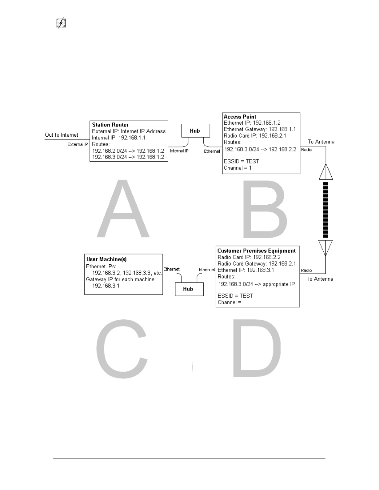
Routing requires proper network subnetting with proper network segmentation. Diagram
1.0 outlines one such network implementation. The accompanying descriptions detail
this implementation.
Page 3 of 27
Page 5
Teletronics International Inc. CPE Complete User Manual
3.0 Network Implementation
===============================================================
Diagram 3.0
• From this point onward an Access Point will be designated AP and a Customer
Premises Equipment will be designated CPE.
Page 4 of 27
Page 6

Teletronics International Inc. CPE Complete User Manual
Description of Diagram 3.0
A. At point A, a station router has access to the Internet though a public IP address. It
has an internal IP of 192.168.1.1. It will route incoming information, destined for
192.168.2.x and 192.168.3.x to the AP's Ethernet IP address of 192.168.1.2 (subnet
mask 255.255.255.0).
B. At point B, the AP's Ethernet IP is 192.168.1.2 (subnet mask 255.255.255.0). The
radio card has an IP of 192.168.2.1 (subnet mask) of 255.255.255.0. Incoming
information destined for 192.168.2.x will be delivered. The AP will route
information destined for 192.168.3.x to 192.168.2.2. The ESSID for the AP is TEST
and the Channel is 1. The AP wireless mode is set to Access Point.
• Please Note: The ESSID for the AP and connected CPE's must be identical.
If they are not, two (or more) physically separate networks will exist and
communications between these networks will not operate.
C. At point C, the CPE's radio card IP is 192.168.2.2 (subnet mask 255.255.255.0). The
Ethernet on the CPE will have an IP of 192.168.3.1 (subnet mask 255.255.255.0).
Any information destined for 192.168.3.x will be routed through the CPE to the
appropriate IP address. The CPE wireless mode is set to Infrastructure.
D. User machines have Ethernet IP addresses of 192.168.3.2, 192.168.3.3, etc. Each has
a gateway of 192.168.3.1.
• Gateways: Gateways must be designated to point at the nearest portal to the
Internet. For example, at D, the gateway is 192.168.3.1. It must point to this
IP. If it does not point to the next nearest portal, communications will not
operate.
• At D, user machines must have a gateway of 192.168.3.1 so information can
be passed to the CPE. At C, the radio card must have a gateway of
192.168.1.2 so information can be passed to the AP. At B, the Ethernet
gateway IP of the AP must have an IP of 192.168.1.1 so information can be
passed to the station router and out to the Internet.
The network implementation described above uses the AP and the CPE as routers, NOT
bridges. Configuring the hardware/software as bridges will increase the amount of
network traffic, and, as a result, will slow the network down. Configuring the
hardware/software as routers will decrease the amount of network traffic and will allow
for optimal performance on your network
Page 5 of 27
Page 7
Teletronics International Inc. CPE Complete User Manual
4.0 User Interface
===============================================================
The user interface for the CPE is browser based. The factory default IP for the CPE is
192.168.1.1. You can interface with the device by connecting the CPE to your computer
via the Ethernet port and typing the following IP address into your Internet browser and
pressing enter, (Please note that you are accessing a secure site -- use https, not http).
https://192.168.1.1
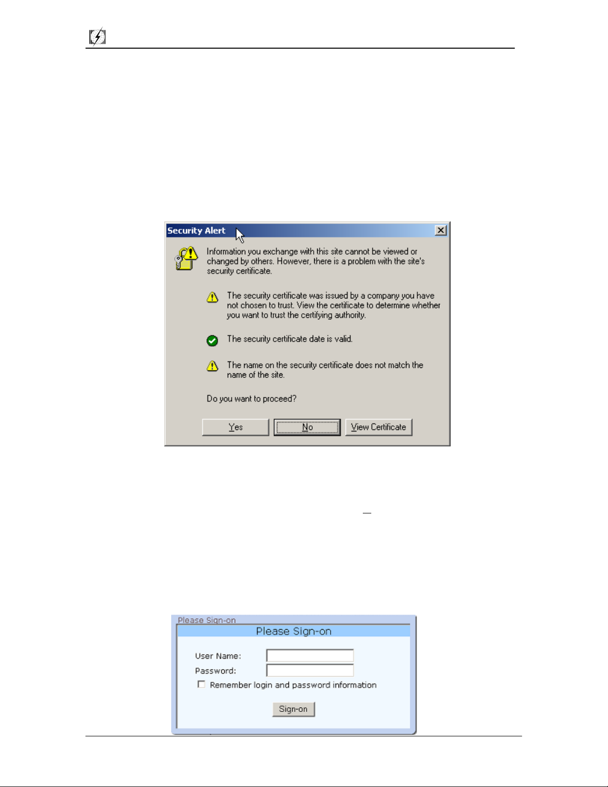
When the CPE is initially accessed, you will be given a Security Alert screen. It is a
harmless warning for the CPE. You will need to click on Yes to proceed.
A sign-on screen will appear which will require a username and a password. The defaults
are case sensitive and are as follows,
Username: admin
Password: 1234
Page 6 of 27
Page 8

Teletronics International Inc. CPE Complete User Manual
With the configuration utility, you will be able to setup the CPE as a CPE, setup the CPE
as an AP, and setup IPs, gateways, subnets, and routes.
Clicking on the side options will take you to a variety of menus which include,
Server Status Page Provides wireless status
Assign W/LAN IP Addresses Allows you to assign IP addresses to
Ethernet and Wireless LAN cards
Static and Default Routes Allows the setup of gateways and routes
Configure Wireless Adapter Allows the configuration of up to 4 wireless
Adapters
IP Masquerading Allows NAT to be enabled or disabled
802.1d for AP and Ethernet Enables or disables bridging only in AP
mode
Change Admin Password Allows the admin password to be changed
Upgrade Firmware Upgrades the current firmware
Restore Factory Defaults Restores the CPE to factory default settings
• When adjusting IP addressing or gateway routes, clicking the line of the address you
wish to modify will automatically choose that address and put the values in the
appropriate fields.
Page 7 of 27
Page 9
Teletronics International Inc. CPE Complete User Manual
5.0 Changing the Admin Password
===============================================================
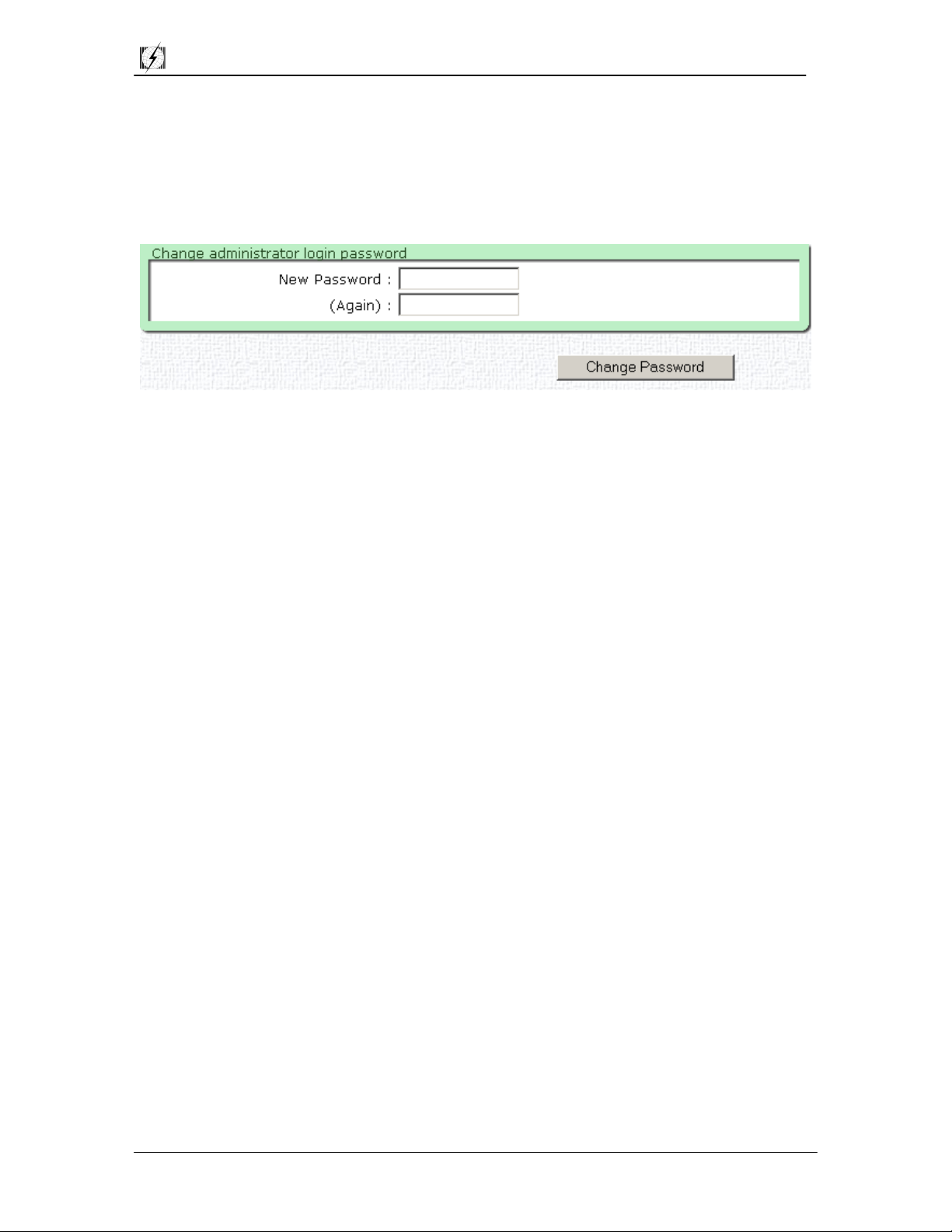
The password can be modified once you are logged in. To do this, click on the Change
Admin Password option on the main CPE Configuration Utility menu.
From this screen, you may change your password (maximum 15 characters). Make sure
the Change Password button is clicked. Otherwis e, the change will not take effect.
Page 8 of 27
Page 10

Teletronics International Inc. CPE Complete User Manual
5.1 Setting up the CPE as a CPE
===============================================================
• The following explanation and screen shots will demonstrate how to set the CPE as a
CPE. The IP addressing explained in this section will reflect the IP addressing as
seen in Diagram 3.0.
• You can save your changes after you have made modification, however, they will not
come into effect until you either save and reboot, or activate. These options are
located at the top left of the CPE Configuration Utility screens.
• Be aware of the Update buttons at the bottom of some configurations screens. Be
sure to click the update buttons, if you have made any changes, before moving on to
other configuration options.
Step 1: Log into the CPE (See Section 4.0 - User Interface)
Step 2: Select Assign W/LAN IP Addresses from the menu on the left
Step 3: Click on All Ethernet and Wireless Adapters
• In Diagram 3.0, the CPE has an Ethernet IP of 192.168.3.1, a radio card IP of
192.168.2.2. The radio card gateway is set at 192.168.2.1. Both cards have a subnet
mask of 255.255.255.0.
Page 9 of 27
Page 11

Teletronics International Inc. CPE Complete User Manual
Step 4: Setting up the ether1 adapter. Click on the default IP (192.168.1.1) to
modify it. The default values will appear in the IP, Net Mask, and Comment
fields. Make your modifications, and then click on the Modify button.
After your modification have been made, checks will appear at the right to
indicate weather or not your changes were appropriate. If you have chosen
IPs that are in conflict, you will be notified with "x"s.
Appropriate Modification Inappropriate Modification
• Important Note: Now that you have modified your ether1 adapter, you must enter
the CPE Configuration Utility through the new IP, in this case, https://192.168.3.1.
Step 5: Setting up the wlan1 adapter. By default, the wlan1 adapter is not setup.
Enter these following values into the following fields:
When you have completed value entries, click the Create button. If there are
no IP conflicts, the software will allow the modifications.
Page 10 of 27
Page 12

Teletronics International Inc. CPE Complete User Manual
Step 6: Select Static and Default Routes option from the menu on the left. enter the
values into the fields as in the below screen shot. Click on the Create button
when you have finished, and then click the Save button at the top left of the
screen.
Step 7: Select IP Masquerading (NAT) from the CPE menu on the left. From here
you can set the CPE to perform IP Masquerading from either the Ethernet card
or the radio card. By default, this function is disabled. Update your settings
if you make any changes from the default setting.
Step 8: Select Slot 1, under the Configure Wireless Adapter option, from the CPE
Configuration Menu on the left. There are 3 different Wireless Network
Cards supported by the CPE Configuration Utility Software. (Please see
section 1.0 Minimum System Requirements). The following sections are
Wireless Network Card specific. Please refer to the appropriate section for
your brand of card.
Page 11 of 27
Page 13

Teletronics International Inc. CPE Complete User Manual
5.2 Setting up the CPE with Teletronics 2Mbit Wireless NIC
• The following explanation and screen shots will demonstrate how to set the CPE with
the Teletronics 2Mbit Wireless Network Card. If your wireless card is not
manufactured by Teletronics, please move to the appropriate section for your card.
Step 9: You will see a screen like the one below. When setting up your CPE to act
as a CPE, the two areas of utmost importance are the ESSID and the
Wireless Mode fields.
The ESSID field must reflect the ESSID of your Access Point. If the
ESSID fields differ between your CPE and your AP, your network will not
function. In Diagram 3.0, the ESSID of both the CPE and the AP is set
to TEST.
The Wireless Mode field for a CPE is always set to Infrastructure. The
only time that this option changes is when you want your CPE to act as an
AP.
Step 10: Click on the Activate button at the top of the screen. This will save all of
your settings and activate any changes you have made to the default settings.
Clicking on Save and Reboot will have the same effect. You have
completed the setup of the CPE as a CPE.
Page 12 of 27
Page 14

Teletronics International Inc. CPE Complete User Manual
5.3 Setting up the CPE with RayLink 2Mbit Wireless NIC
• The following explanation and screen shots will demonstrate how to set the CPE with
the RayLink 2Mbit Wireless Network Card. If your wireless card is not
manufactured by RayLink, please move to the appropriate section for your card.
Step 9: You will see a screen like the one below. When setting up your CPE to act
as a CPE, the two areas of utmost importance are the ESSID and the
Wireless Mode fields.
The ESSID field must reflect the ESSID of your Access Point. If the
ESSID fields differ between your CPE and your AP, your network will not
function. In Diagram 3.0, the ESSID of both the CPE and the AP is set
to TEST.
The Wireless Mode field for a CPE is always set to Infrastructure. The
only time that this option changes is when you want your CPE to act as an
AP.
Step 10: Click on the Activate button at the top of the screen. This will save all of
your settings and activate any changes you have made to the default settings.
Clicking on Save and Reboot will have the same effect. You have
completed the setup of the CPE as a CPE.
Page 13 of 27
Page 15

Teletronics International Inc. CPE Complete User Manual
5.4 Setting up the CPE with PrismII 11Mbit Wireless NIC
• The following explanation and screen shots will demonstrate how to set the CPE with
the PrismII 11Mbit Wireless Network Card. If your wireless card is not based on the
PrismII chipset, please move to the appropriate section for your card.
Step 9.0: You will see a screen like the one below. When setting up your CPE to act
as a CPE, the two areas of utmost importance are the ESSID and the
Wireless Mode fields.
The ESSID field must reflect the ESSID of your Access Point. If the
ESSID fields differ between your CPE and your AP, your network will not
function. In Diagram 3.0, the ESSID of both the CPE and the AP is set to
TEST.
The Wireless Mode field for a CPE is always set to Infrastructure. The
only time that this option changes is when you want your CPE to act as an
AP.
Step 9.1: When the CPE is in infrastructure mode, any modifications made in the
Access Point Settings do not affect the functioning of the CPE. When setting up a
CPE as a CPE, these values are not used.
Page 14 of 27
Page 16

Teletronics International Inc. CPE Complete User Manual
Step 9.2: (Optional) The PrismII Wireless Network Card has the ability to send and
receive encrypted transmissions. This function allows only CPEs and APs
with appropriate keys to communicate and disallows unauthorized use. The
following procedure will provide details on how to use this function. It is
important to note that both the AP and the CPE must support this function
and must be using identical keys. It is highly recommended that you make
sure your network is functioning before utilizing any WEP functions.
By default, WEP settings are disabled. You can activate WEP either by
using 64 or 128 bit encryption keys.
When 64 bit encryption is enabled, 4 keys are created, enabling the
switching of keys from time to time. When 128 bit encryption is enabled,
only 1 key is generated. In order to switch to a different key, a new
passphrase is required.
Steps in enabling WEP
i. Choose which level of encryption you would like using the drop
down WEP support option.
ii. Choose how you would like to enter your key using the drop down
key entry option (manual or passphrase). Manual entry allows your
to manually enter your keys using hexadecimal values. Passphrase
creates hexadecimal values from the characters you enter into the
passphrase field. The maximum number of characters allowed in the
passphrase field is 35.
iii. After you have either entered manual values, or have selected a
passphrase, click on the Update Settings button on the bottom of the
screen.
iv. After you have updated the settings, the keys will be displayed, as
below. (The example on the following page uses 64 bit encryption
and a passphrase)
Page 15 of 27
Page 17

Teletronics International Inc. CPE Complete User Manual
Step 10: Click on the Activate button at the top of the screen. This will save all of
your settings and activate any changes you have made to the default settings.
Clicking on Save and Reboot will have the same effect. You have
completed the setup of the CPE as a CPE.
Page 16 of 27
Page 18

Teletronics International Inc. CPE Complete User Manual
6.0 Setting up the CPE as an Access Point
===============================================================
• The following explanation and screen shots will demonstrate how to set the CPE as
an AP. The IP addressing explained in this section will reflect the IP addressing as
seen in Diagram 3.0.
• You can save your changes after you have made modification, however, they will not
come into effect until you either save and reboot, or activate. These options are
located at the top left of the CPE Configuration Utility screens.
• Be aware of the Update buttons at the bottom of some configurations screens. Be
sure to click the update buttons, if you have made any changes, before moving on to
other configuration options.
Step 1: Log into the CPE (See Section 4.0 - User Interface)
Step 2: Select Assign W/LAN IP Addresses from the menu on the left
Step 3: Click on All Ethernet and Wireless Adapters
• In Diagram 3.0, the AP has an Ethernet IP of 192.168.1.2, a radio card IP of
192.168.2.1. The radio card gateway is set at 192.168.1.1. Both cards have a subnet
mask of 255.255.255.0.
Page 17 of 27
Page 19

Teletronics International Inc. CPE Complete User Manual
Step 4: Setting up the ether1 adapter. Click on the default IP (192.168.1.1) to
modify it. The default values will appear in the IP, Net Mask, and Comment
fields. Make your modifications, and then click on the Modify button.
After your modification have been made, checks will appear at the right to
indicate weather or not your changes were appropriate. If you have chosen
IPs that are in conflict, you will be notified with "x"s.
Appropriate Modification Inappropriate Modification
• Important Note: Now that you have modified your ether1 adapter, after you click the
Activate button or the Save and Reboot buttons, you must enter the CPE
Configuration Utility through the new IP, in this case, https://192.168.1.2.
Step 5: Setting up the wlan1 adapter. By default, the wlan1 adapter is not setup.
Enter these following values into the following fields:
When you have completed value entries, click the Create button. If there are
no IP conflicts, the software will allow the modifications.
Page 18 of 27
Page 20

Teletronics International Inc. CPE Complete User Manual
Step 6: Select Static and Default Routes option from the menu on the left. Enter the
values into the fields as in the below screen shot. Click on the Create button
when you have finished, and then click the Save button at the top left of the
screen.
Step 7: Select IP Masquerading (NAT) from the CPE menu on the left. From here
you can set the CPE to perform IP Masquerading from either the Ethernet card
or the radio card. By default, this function is disabled. Update your settings
if you make any changes from the default setting.
Step 8: Select 802.1d for AP and Ethernet under the Configure Network Bridges
menu on the left. Here, you can specify bridging if necessary. If your
network is setup as in Diagram 3.0, bridging in not necessary, and you can
skip this step. If however, your network is not setup as in the diagram, and
bridging is required, you will need to make sure that the bridge values are the
same for both ether1 and wlan1. Be sure to Update Bridge Information
after you have made any modifications other than leaving the settings as
disabled.
Page 19 of 27
Page 21

Teletronics International Inc. CPE Complete User Manual
Step 9: Select Slot 1, under the Configure Wireless Adapter option, from the CPE
Configuration Menu on the left. There are 2 different Wireless Network
Cards supported by the CPE Configuration Utility Software that can be placed
in Access Point Mode. (Please see section 1.0 Minimum System
Requirements). The following descriptions are Wireless Network Card
specific. Please refer to the appropriate section for your brand of card.
Page 20 of 27
Page 22

Teletronics International Inc. CPE Complete User Manual
6.1 Setting up the CPE as an AP with Teletronics 2Mbit Wireless NIC
• The following explanation and screen shots will demonstrate how to set the CPE with
the Teletronics 2Mbit Wireless Network Card. If your wireless card is not
manufactured by Teletronics, please move to the appropriate section for your card.
Step 9.1: You will see a screen like the one below. When setting up your CPE to act
as a CPE, the two areas of utmost importance are the ESSID and the
Wireless Mode fields.
The ESSID field must reflect the ESSID of your CPE. If the ESSID fields
differ between your CPE and your AP, your network will not function. In
Diagram 3.0, the ESSID of both the CPE and the AP is set to TEST.
The Wireless Mode field for an AP is always set to Access Point. The
only time that this option changes is when you want your AP to act as an
CPE.
Step 10: Click on the Activate button at the top of the screen. This will save all of
your settings and activate any changes you have made to the default settings.
Clicking on Save and Reboot will have the same effect. You have
completed the setup of the CPE as an AP.
Page 21 of 27
Page 23

Teletronics International Inc. CPE Complete User Manual
6.11 Additional Functions with Teletronics 2Mbit Wireless NIC:
• An additional feature of using the Teletronics 2Mbit Wireless NIC in the CPE in AP
mode is that the AP can determine signal strength of stations connected to the AP.
By default, this function is fully enabled and can be accessed through the Server
Status Page option in the main CPE Configuration Utility menu.
i. Once on the Server Status Page, click on the client list under the
Assoc. Stations header.
ii. You will then be able to view the signal strength of connected stations.
Page 22 of 27
Page 24

Teletronics International Inc. CPE Complete User Manual
6.2 Setting up the CPE as an AP with PrismII 11Mbit Wireless NIC
• The following explanation and screen shots will demonstrate how to set the CPE with
the PrismII 11Mbit Wireless Network Card. If your wireless card is not based on the
PrismII chipset, please move to the appropriate section for your card.
Step 9.1: You will see a screen like the one below. When setting up your CPE to act
as a CPE, the two areas of utmost importance are the ESSID and the
Wireless Mode fields.
The ESSID field must reflect the ESSID of your CPE. If the ESSID fields
differ between your CPE and your AP, your network will not function. In
Diagram 3.0, the ESSID of both the CPE and the AP is set to TEST.
The Wireless Mode field for an AP is always set to Access Point. The
only time that this option changes is when you want your AP to act as an
CPE.
Step 9.2: When the CPE is in infrastructure mode, any modifications made in the
Access Point Settings do not affect the functioning of the CPE. When setting up a
CPE as a AP, these values are used. The channel range available is from 1 to 11
inclusive. If WEP is enabled (see Step 9.3), you may set the Allow non-encrypted
field to No.
Page 23 of 27
Page 25

Teletronics International Inc. CPE Complete User Manual
Step 9.3: (Optional) The PrismII Wireless Network Card has the ability to send and
receive encrypted transmissions. This function allows only CPEs and APs
with appropriate keys to communicate and disallows unauthorized use. The
following procedure will provide details on how to use this function. It is
important to note that both the AP and the CPE must support this function
and must be using identical keys. It is highly recommended that you make
sure your network is functioning before utilizing any WEP functions.
By default, WEP settings are disabled. You can activate WEP either by
using 64 or 128 bit encryption keys.
When 64 bit encryption is enabled, 4 keys are created, enabling the
switching of keys from time to time. When 128 bit encryption is enabled,
only 1 key is generated. In order to switch to a different key, a new
passphrase is required.
Steps in enabling WEP
i. Choose which level of encryption you would like using the dro p down WEP
support option.
ii. Choose how you would like to enter your key using the drop down key entry
option (manual or passphrase). Manual entry allows your to manually enter
your keys using hexadecimal values. Passphrase creates hexadecimal values
from the characters you enter into the passphrase field. The maximum
number of characters allowed in the passphrase field is 35.
iii. After you have either entered manual values, or have selected a passphrase,
click on the Update Settings button on the bottom of the screen.
iv. After you have updated the settings, the keys will be displayed, as in the
diagram on the next page. (The diagram uses 64 bit encryption and a
passphrase).
Page 24 of 27
Page 26

Teletronics International Inc. CPE Complete User Manual
Step 10: Click on the Activate button at the top of the screen. This will save all of
your settings and activate any changes you have made to the default settings.
Clicking on Save and Reboot will have the same effect. You have
completed the setup of the CPE as an AP.
Page 25 of 27
Page 27

Teletronics International Inc. CPE Complete User Manual
7.0 Updating the CPE Firmware
===============================================================
Updating the CPE firmware is an option on the main menu of the CPE Configuration
Utility. The version of your CPE firmware can be determined by looking at the top of the
CPE Configuration Utility.
In this example, the firmware is version 2.10.
In order to update the CPE firmware the following steps are necessary. Please be
advised, that upgrading firmware on the CPE, as any device, is a risk. Should the CPE
lose power or have an unexpected error during the upgrade process, the unit may become
unusable. Should this happen, you will need to have the software re-uploaded to the
internal flash card. Upgrading firmware is necessary only if you require the features
added in the new version. Upgrading firmware is done so at your own risk.
7.1 Steps to upgrading CPE firmware:
Step 1: Download the firmware update utility - currently FIRMUPL102.EXE
Step 2: Download the firmware binary update file.
Step 3: Click on the Upgrade Firmware option in the Administrative Functions on the
CPE Configuration Utility Menu.
Step 4: The CPE will provide you with a message and a button labeled Proceed. If
you are certain you wish to upgrade the firmware, click the Proceed button
and continue with the next step.
Step 5: At this time the CPE is awaiting commands and data to perform the upgrade.
At a DOS command prompt, type the name of the firmware update
executable, followed by the IP address of the CPE and then followed by the
name of the binary firmware. The syntax for the firmware update utility is,
firmupl102 ip-address firmware.bin
ie: firmupl102 192.168.1.1 cpe-213.bin
Step 6: The firmware update will update the CPE. Once completed, you will see the
following message.
Page 26 of 27
Page 28

Teletronics International Inc. CPE Complete User Manual
CPE Firmware upgrade utility version 1.02-win32
Windows port - Aug 21, 2001. BETA
MD5 Checksum for this file: 6cefdf7df87bee06884b5af845e71438
Connected: CPE is currently running firmware version 2.13-pr2
Sending firmware, please wait....
[##################################################] - 8028160 (7840K)
Firmware has been sent.
Finished. Waiting for server to verify the firmware....
Success! The CPE will now reboot using the new firmware.
Step 7: You will need to wait for 2 minutes, while the CPE is checking the firmware and
rebooting. After rebooting, you may connect to the CPE using the regular
protocol (See Section 4.0 User Interface). You can now configure the settings
using the web browser, as described.
Page 27 of 27
 Loading...