

Page 1

WINC 900A Wireless Modem
Owner’s Manual
TELETRONICS INTERNATIONAL, INC.
Rockville, Maryland, USA, 20850-3155
1
Page 2

Serial Number:
Remote Unites
Serial Number Remarks
2
Page 3

Copyright ©1999
by
Teletronics International, Inc.
All Rights Reserved. No part or parts of this document may be reproduced, translated,
stored in any electronic retrieval system, or transmitted, in any form or by any means,
electronic, mechanical, photocopying, recording, or otherwise, without the prior written
permission of the copyright holder.
3
Page 4

LIMITED WARRANTY
The WINC 900A is warranted to the original purchaser to be free from defects in
materials and workmanship under normal installation, use, and service for a period of
one (1) year from the date of purchase.
Under this warranty, Teletronics International, Inc. shall repair or replace (at its
option), during the warranty period, any part that proves to be defective in material of
workmanship under normal installation, use and service, provided the product is
returned to Teletronics International, Inc., or to one of its distributors with
transportation charges prepaid. Returned products must include a copy of the
purchase receipt. In the absence of a purchase receipt, the warranty period shall be
one (1) year from the date of manufacture.
This warranty shall be voided if the product is damaged as a result of defacement,
misuse, abuse, neglect, accident, destruction or alteration of the serial number,
improper electrical voltages or currents, repair, alteration or maintenance by any
person or party other than a Teletronics International, Inc. employee or authorized
service facility, or any use in violation of instructions furnished by Teletronics
International, Inc.
This warranty is also rendered invalid if this product is removed from the country in
which it was purchased, if it is used in a country in which it is not registered for use, or
if it is used in a country for which it was not designed. Due to variations in
communications laws, this product may be illegal for use in some countries.
Teletronics International, Inc. assumes no responsibility for damages or penalties
incurred resulting from the use of this product in a manner or location other than that
for which it is intended.
IN NO EVENT SHALL TELETRONICS INTERNATIONAL, INC. BE LIABLE
FOR ANY SPECIAL, INCIDENTAL OR CONSEQUENTIAL DAMAGES FOR
BREACH OF THIS OR ANY OTHER WARRANTY, EXPRESSED OR IMPLIED,
WHATSOEVER.
Some states do not allow the exclusion or limitation of special, incidental or
consequential damages, so the above exclusion or limitation may not apply to you.
This warranty gives you specific legal rights, and you may also have other rights that
vary from state to state.
4
Page 5

Table Of Contents
Page #
1.0 OVERVIEW 6
2.0 TECHNICAL INFORMATION 6
3.0 EQUIPMENT CHECK LIST 6
4.0 INSTALLATION AND COMMUNICATING WITH THE WINC 900A 8
4.1 HARDWARE CONNECTION 8
4.2 COMMUNICATION SOFTWARE SETTINGS 9
4.3 COMMUNICATING WITH THE WINC 900A 11
5.0 AVAILABLE OPERATION MODES IN WINC 900A & APPLICABLE
APPLICATIONS 13
5.1 SUMMARY OF VARIOUS OPERATION MODES, APPLICABLE
APPLICATIONS, AND FAQ 14
5.1.1.1 POINT-TO-POINT DIAL-UP CONNECTION OPERATION
MODE 14
5.1.1.2 APPLICABLE APPLICATIONS
5.1.2.1 POINT-TO-POINT AUTO CONNECTION OPERATION MODE 15
5.1.2.2 APPLICABLE APPLICATIONS
5.1.3.1 MULTIPLE-TO-ONE DYNAMIC DATA REPORTING &
MONITORING MODE 16
5.1.3.2 APPLICABLE APPLICATIONS
5.1.4.1 MULTIPLE-TO-MULTIPLE TRANSPARENT OPERATION
MODE 19
5.1.4.2 APPLICABLE APPLICATIONS
5.2 FAQ AND SYSTEM ADJUSTMENT 20
6.0 WINC 900A INTERFACE STATUS 22
7.0 AT COMMAND SET 24
7.1 AT COMMAND SYNTAX 24
7.2 BASIC AT COMMANDS 25
7.3 EXTENDED AT COMMAND SET 30
7.4 S REGISTERS 33
7.5 COMMONLY USED AT COMMANDS WITH THE WINC 900A 33
APPENDIX A - AT COMMANDS FOR THE WINC 900A 36
APPENDIX B - S REGISTER SUMMARY 39
APPENDIX C - WINC 900A SPECIFICATION 44
ADDITIONAL SUPPORT
5
Page 6

1.0 Overview
Teletronics' advanced WINC 900A1 wireless modem facilitates the transfer of information among
computers and peripherals without cables and expensive network operating systems. The device
operates at very low power in the ISM frequency band between 902 and 928 MHz and requires no
licensing by the FCC. Using state-of-the-art spread spectrum technology, the WINC 900A offers
reliable point-to-point data communication even when computers and peripheral devices are
separated by walls, floors, and ceilings or dispersed in mobile or temporary facilities.
The WINC 900A is Hayes-AT compatible, simple to operate, and supported by most commercially
available communications software packages such as PROCOMM™ , PC-ANYWHERE™ ,
XTALK™, etc. Data rates are user-selectable and vary from 300 bps to 38400 bps.
2.0 Technical Information
The WINC 900A transfers data asynchronously between computers or peripherals at user defined
data rates of 0.3, 0.6, 1.2, 2.4, 4.8, 9.6, 19.2 and 38.4 kbps and connects to the serial port of either a
computer or peripheral via an RS-232 DB-25 connector. Data formats are selectable as follows:
Data: 7 or 8 bits, Parity: even/odd/none, Stop bit: 1 or 2. Hardware and software flow control are
supported via RTS/CTS and XON/XOFF, respectively. The WINC 900A operates full-duplex,
using the standard Hayes-AT command set, and can be configured for point-to-point or networked
operation. A complete listing of the available AT commands is included in Section 7.0.
The WINC 900A operates in the 902-928 MHz frequency band with a maximum power of 1 watt.
Eight independent 3 MHz wide channels are available within this band. Outdoors, the operating
range of the modem is approximately 1 kilometer. Depending on the material of walls and ceilings,
indoor operation may be limited to approximately 100 meters.
The WINC 900A uses direct sequence spread spectrum signaling with a variable PN spreading rate.
The device operates full-duplex using differentially encoded QPSK modulation. Sensitivity for this
system is -85dBm (not including spreading gain). See Appendix C for a detailed technical
specification of the device.
In general, the WINC 900A operates automatically with little need for user intervention. Both
channel selection and power control are automatic and transparent to the user guarantying that
communications occurs at the least power required to maintain the link on the selected channel.
3.0 Equipment Check List
The WINC 900A package contains the following items.
1. One (1) WINC 900A wireless modem
2. One (1) WINC 900A operation manual
3. One (1) warranty card
4. One (1) power cord
5. One (1) rubber omni antenna
6. Two (2) stands for vertical placement
1
WINC is a trademark of Teletronics International, Inc. All other trademarks or references to other
commonly used software or hardware are the property of their respective companies.
6
Page 7

If anything is missing or damaged, please contact your supplier immediately.
Each WINC 900A is uniquely identified by an seven (7) digit address that is used when two units
attempt to establish a communications link. The seven (7) digit address is found on the label affixed
to the left side of the unit and is defined by the right-most seven (7) digits of the serial number. The
device address can also be found by using the ATI0 command discussed in section 7.2.
7
Page 8
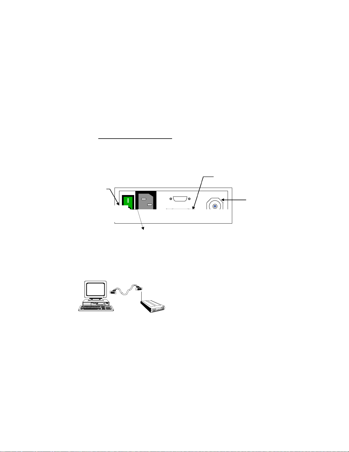
4.0 Installation and Communicating with the WINC 900A
Antenna
Female Connector
The communication between the WINC 900A and your computer, terminal, or peripheral requires a
simple connection using a straight through serial cable with proper connector at each ends. The
following two sections will help you to walk through the hardware connection and the communication
software test processes before you can communicate with WINC 900A directly.
4.1 Hardware Connection
Step 1: Preparation before installation :
Required equipment:
-- two (2) 386/486 IBM PCs with one DB-25 or DB-9 serial port each
-- two (2) straight through serial cables, with a male DB-25 at one end for WINC 900A
and a male/female DB-25/DB-9 at the other end for the serial port of your PC.
Step 2: Cabling
DB-25 Serial Port
Power Switch
N type
AC Power In
Fig 4-1. Back Panel Layout of WINC 900A
1. Turn your computer off before starting.
2. Connect the DB-25 serial port of the WINC 900A to the serial port of your computer
using a straight through serial cable with RS-232 DB-25 connectors at each end.
(please refer to Fig. 4-2) Although the WINC 900A is configured to accept a DB-25
connector directly, a DB-9 connector may be used with the proper adapter. (The cable with
connector is not supplied with the
WINC 900A, but is available from
most computer retailers and electronics
suppliers.)
Fig 4-2. Serial Port to Serial Port Connection
3. Connect the power cord to the rear of the unit and plug it into the electrical jack nearest
your equipment. (please refer to Fig. 4-1) The WINC 900A is equipped with a universal
power supply for 110-220 volts and will internally adjust itself for either voltage.
4. Fasten the rubber omni antenna to the antenna connector of the WINC 900A or attach
your Yagi antenna to the antenna connector of the WINC 900A using shielded low lost
cable with TNC to N type connector.
5. Turn on the computer.
8
Page 9

6. Turn on the WINC 900A modem. The WINC 900A performs a brief self-test via resident
communications software. After the initialization of the communication software on the PC,
the front panel LEDs2 indicate the state of the WINC 900A. If cabling is properly done,
the DTR, DSR, CTS and RTS indicators should be green, whereas the RI, DCD, RxD,
and TxD indicators are red after the WINC 900A is initially powered up .
After the completion of the hardware connection between your PC and the WINC 900A , you must
follow the same steps above working on the 2nd unit.
4.2 Communication Software Settings
Although the WINC 900A is a sophisticated wireless modem and integrated spread spectrum
transceiver, it has been designed to be compatible with off-the-shelf communications software
typically used with conventional land-line modems. Consequently, if you have not already done so,
install the appropriate data communications software into your computer before proceeding further.
Please note, due to the popularity of MS-Windows, the Terminal in the Accessories of MS Window
3.1 will be used in the following process as guidance. But, the maximum baud rate of MS
Terminal is 19.200Kbps only; therefore, it requires other communication software to reach
38.400Kbps.
Step 1: Activate your communication software
1. Running MS-Windows, and then activate the Terminal in Accessories.
2. Click the “Settings” ,and then activate the “Communications” dialog box.
Step 2: Configure your communication software to meet default value of WINC 900A
1. Click on the available serial port from the “Connector” list,
2. Click on the 9600 from the “Baud Rate” list,
3. Click on “OK” return to the Terminal.
All selectable items in the communication dialog box will turn into active (high-lighted), if
the selected serial port is available on your computer. Otherwise, stop here and consult
with a computer expert knowledgeable about setting up serial port for you.
Step 3: Communicate with WINC 900A via AT command
1. Press the “Enter” key.
You should get an “ERROR” whenever you press the Enter key without AT commands.
2. Try type in “ATI0”
You should get response similar to the followings:
MODEM address: xxxxxxxx
Current channel: 0
(The MODEM address should match the right-most seven (7) digits of the serial number
digit found on the label affixed to the left side of the unit.)
After the configuration setup process above, the communications software will go into the
local-terminal or direct-connection mode. All AT commands for WINC 900A will be sent
to the serial port directly, accepted and executed by WINC 900A.
2
See Section 7.0, WINC 900A Interface Status, for LED indicator definitions.
9
Page 10
There is a possibility that you will get some funny characters or no response resulting from
the different baud rate settings on the communications software and the WINC 900A. If
this happens, please reset the WINC 900A back to the manufacturer’s default setting -9600 bps as instructed below.
Whenever you need to clear the settings, you can issue AT command AT&F to reset the
WINC 900A to the original factory default conditions. An alternative method for
accomplishing this is to hold the reset button on the front panel and turn on the power of
WINC 900A. (please refer to Fig. 4-3) A pencil, pen or other sharply pointed object is
required to access the button through the hole on the front panel.
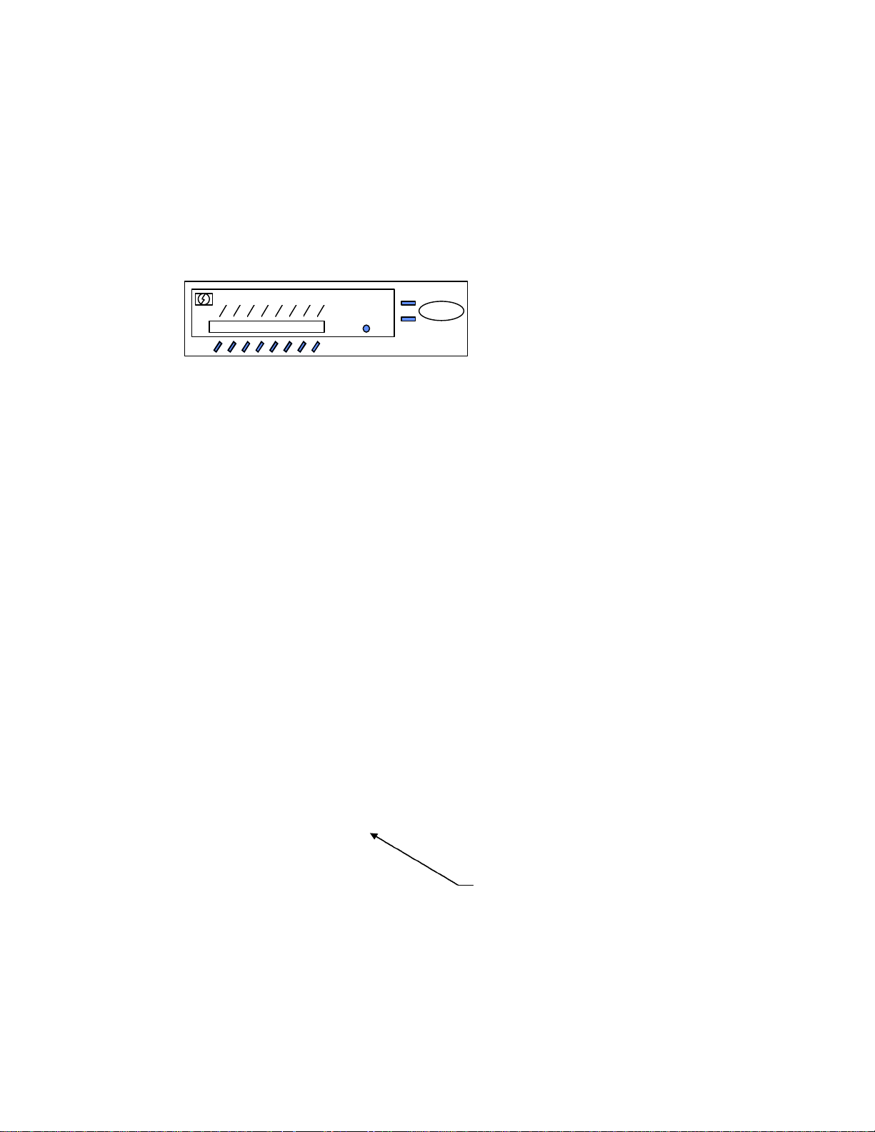
TxD
RxD
FULL DUPLEX INTERFACE
Power
Signal
Reset
Winc 900A-Car
Fig 4-3. WINC 900A Front Panel
Teletronics Wireless Modem
RI
CTS
DSR
RTS
DTR
DCD
Step 4: Save the configuration settings
of your communications of software
If you already completed the steps above without problems, you may select the “Save” from
the “File” option in the MS-Windows Terminal and save the configuration settings for the
future before you leave Terminal.
If you still have problems communicating with the WINC 900A from your computer, please work on
the followings step by step, and then start all over again from the beginning of this chapter or walk
through our recommendation below.
1. Contact your computer hardware engineer, verify the availability of the serial port (com port) on
your computer, and working on this until the serial port is available to you.
2. Connect your serial port with an external modem and work on the communication software
setting until you get the dial tone, dialing out successfully.
3. Replace the external modem with WINC 900A. At this point, go through the factory default
setting process above to make sure that 9600 is the default baud rate on WINC 900A.
4. Please work from the beginning of chapter 4.0 again.
5. If you still have problems communicating with the WINC 900A, please visit our Web
Customer Support page at www.teletronics.com or fill out the technical support request
form at the last page with all details and fax it to our “Technical Support Team” located in our
US headquarters.
4.3 Communicating with the WINC 900A
Once the WINC 900A and the communications software have been installed, the device is ready to
use. You can communicate directly with the WINC 900A using the AT command set, the
communications software should allow you to put the computer into the local-terminal or direct-
Default Reset Button Hole
connection mode.
A connection between the local and remote WINC 900A is automatically established on the channel
that provides the best performance. However, if you come across difficulty to operate WINC 900A
on your learning curve. The AT command AT&F is used to reset the WINC 900A to the original
factory default conditions. An alternative method for accomplishing this is to use the reset button on
10
Page 11

the front panel of the device. A pencil, pen or other sharply pointed object is required to access the
button through the hole on the front panel.
4.3.1 Establish Connection and Function Test
Step 1. Establish Communication with WINC 900A (execute followings at both PCs)
1. Execute MS-Windows
2. Activate the Terminal in the Accessories
3. Select the Settings, and then click on the “communications” option
4. Click on the available com port from the connectors list
5. Click on the 9600 from the baud rate list.
6. Click on the OK, which will bring you back to the Terminal and stay in the local
terminal mode.
7. Press “Enter” key without AT command. You should get an “ERROR” as response.
Step 2. Establish connection with remote WINC 900A
1. Get the remote station’s address, the right-most seven (7) digits of the serial number
digit found on the label affixed to the left side of the unit.
2. Type in AT connection command ATDT with seven (7) digit remote address as
“ATDTxxxxxxx”.
3. You should get a “CONNECT” as response at both sides.
4. If you did get the “CONNECT” response, you will stay in direct connection mode until
you type in the escape sequence “+++”.
5. If you did not get the “CONNECT” response and system halt. Please reboot the WINC
900A, verify the remote address, and try the AT connection command again.
6. In the connection mode, you may start to type some message on one of your computers
The typed in message will be displayed on the screen of the remote side.
Step 3. Function test on file transfer
1. Click on the “Transfers” from the menu bar of Terminal.
2. Click on the “Send Text File”
3. Select one of the text files from the file list, and then click on OK.
4. You should be able to see the content of the text file on the screen of the remote side.
Also, the transferred file will be created on the remote side, if your friend can help you out
on the remote side, select the “Receive Text File” option from the “Transfers”, and assign a
file name for the in-coming file.
Step 4. Disconnect established link between two WINC 900As
The WINC 900A only responds to AT commands when in the command or off-line mode.
Consequently, to terminate a connection, the unit must escape to this mode before it will
respond. This is accomplished by issuing the escape sequence "+++". Once in the
command mode, the AT command ATH is issued to close the connection.
While the basic AT command set is generic and applies to most land-line modems, a number of AT
commands unique to the WINC 900A are included in Section 7.3. These commands are used to
control air-link specific parameters like the channel number and other operational characteristics.
For completeness, the basic and extended AT command set is described in Section 7.0. In addition,
Appendix A contains the Standard AT Modem Commands and Appendix B contains the S Register
Summary.
11
Page 12
5.0 Available operation modes in WINC 900A and Applicable applications
Resulting from our long term commitments to our products and tight relationship with our customers,
WINC 900A can be configured to various operation modes as followings:
1. Point-to-Point Dial-up connection mode
2. Point-to-Point Auto connection mode
3. Multiple-to-One Wireless Dynamic Data Reporting and Monitoring (WDDR) mode
4. Multiple-to-Multiple Transparent mode
The first two operation modes, the Point-to-Point Dial-up connection mode and the Point-to-Point
Auto connection mode, were developed on the foundation of the traditional point-to-point
asynchronous mechanism that comes with build-in protocol providing error free data transmission.
In the 3rd operation mode, the Multiple-to-One Wireless Dynamic Data Reporting and Monitoring
operation mode, the build-in broadcasting function transmits the in-coming data from the connected
external device to the air. All remote units operate/broadcast without build-in protocols for packet
collision prevention and packet re-transmission; therefore, the transmitted packets from remote units
might not be received by the information collection unit.
In the Multiple-to-Multiple transparent mode, each WINC 900A operates as a dumb transceiver fully
controlled by industry oriented management systems in transmitting and receiving packet to/from the
air. The correctness of the data is totally relay on the upper level management system. There is
no involvement of build-in protocols from WINC 900A.
5.1 Summary of various operation modes, applicable applications, and FAQ
5.1.1.1 Point-to-Point Dial-up connection operation mode
The spirit of WINC 900A asynchronous modem development is to deliver a wireless
asynchronous modem using traditional dial-up connection mechanism with error free protocol.
The dial-up connection process has been detailed in section 4.3.1. After the establishment of
the point-to-point linkage connection, the user can perform the functionality provided by the
communication software just like the connection established between two PC modems via
telephone line.
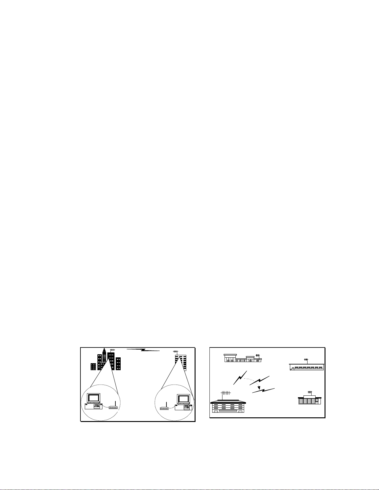
5.1.1.2 Applicable applications
• The traditional remote dial-up connection
• The one-to-multiple polling connection for data distribution or data collection process.
Branch 1
WINC 900A
WINC 900A
Central Office
Branch 2
Branch 3
Food Mart
Traditional Dial-up Connection
The user issues the ATDT command
or activate the connection function
from the communication software to
the remote unit and establish the pointto-point connection.
12
One-to-multiple Polling Connection
The user adopts the polling mechnism
in their application program and
initiates the dial-up function to
establish wireless connection with each
remote units by turns.
Page 13
5.1.2.1 Point-to-Point Auto connection operation mode
Extended cable connection for dial-up
As addressed above, the established
wireless link can be used as wire to
extend the cable wirelessly.
Besides of the traditional dial-up connection above, a pair of WINC 900A can be operated in
auto connection mode in order to establish a point-to-point permanent wireless linkage.
In the point-to-point auto connection operation, one of the two units will play a roll as Master
unit, the user must issue the following AT commands to specify the address of the slave unit
and to enable the auto connection operation at the Master unit.
AT commands issued at the Master unit to specify the address of the slave unit and to enable the
auto connection function are :
AT~Axxxxxxx
(“xxxxxxx” above stands for the 7 digit address of the slave unit)
AT&!1
(to enable the auto connection function)
After initiating the auto connection operation, the Master unit will issue the connection request
to the specified slave unit, establish connection, and go into connection mode. The Master unit
will automatically recover the established wireless connection after the drop of linkage resulting
from power outage or interference. Before issuing AT commands for configuration change or
terminating the auto-connection function, users must issue the escape sequence, holding the
“Shift” key and pressing “+” key 3 times, to return to the command mode.
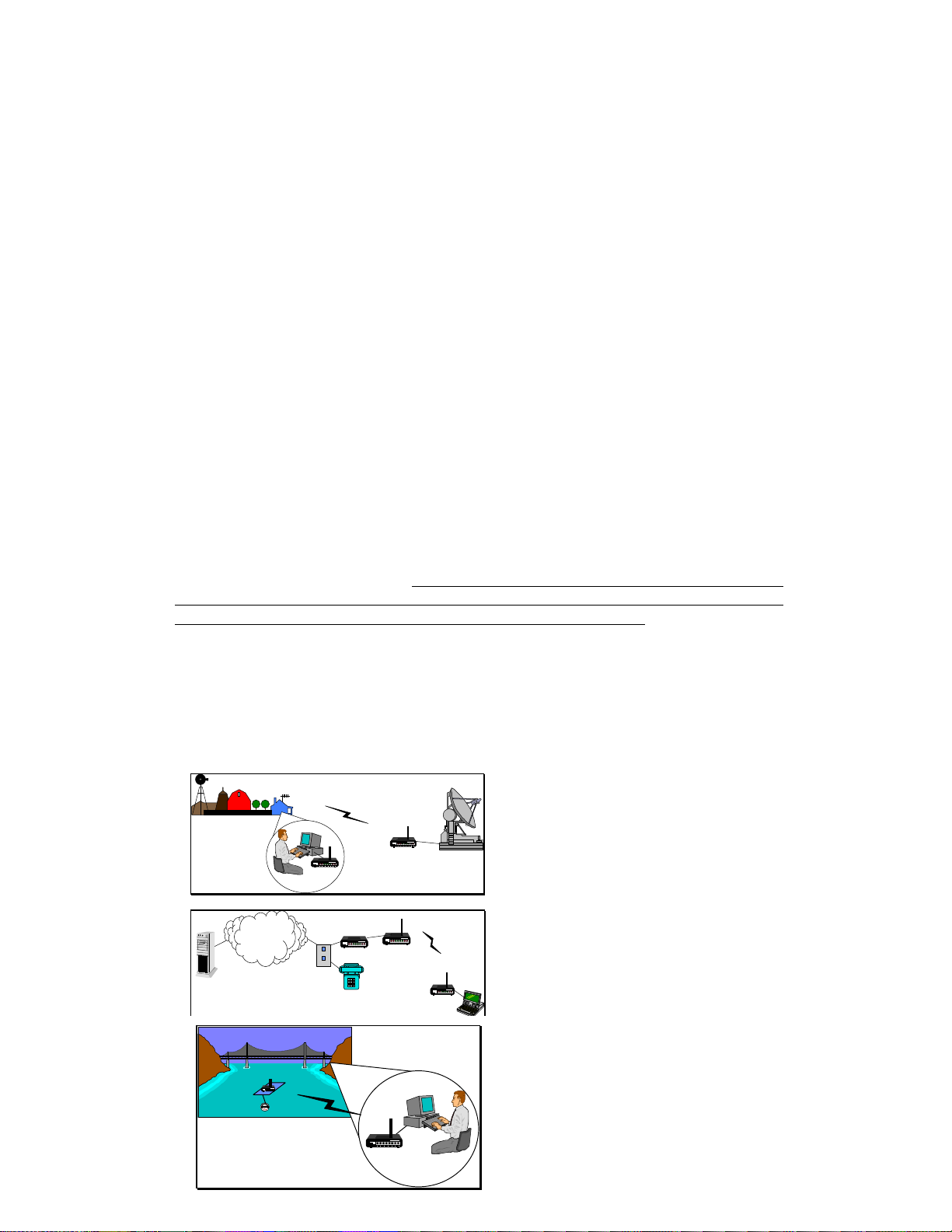
5.1.2.2 Applicable applications
• The extended cable connection for dial-up connection.
• The point-to-point perminal link connection
• The leasing line replacement
• The last mile connection
ISP
PSTN
WINC 900A
PC Modem
WINC 900A
WINC 900A
WINC 900A
Last mile extension connection
The established wireless link can be
used as wires between two locations
for data transmission.
WINC 900A
Point to-Point Permanent Connection
WINC 900A is the ideal equipment to
establish wireless link for data acquisition
application. WINC 900A has a DC mode.
User is capable to activate the connected
external device at the remote site with
required “BREAK” signal.
13
Page 14

Leasing line replacement
Due to the build-in error free protocol and
the connection auto-recovery capability, the
wireless connection established by WINC
900A is the ideal to be used in replacing the
costly leasing line.
5.1.3.1 Multiple-to-One Dynamic Data Reporting and Monitoring mode
In the Point-to-Point operation modes above, the build-in protocol ensures that all transmitted
packets between two points will be delivered to the receiver promptly without error. But, in
the Multiple-to-One wireless applications architecture, it is very difficult to specify the break
point of satisfaction on performance with the same guarantee on error free.
For some non-timing sensitive Multiple-to-One applications, WINC 900A can be configured
into three different broadcasting mode as followings :
Operation
Mode
WINC-900A
AT
General Description
command
AT~P1 refer to manual 5.1.1 section
Regular Asyn.
Mode
WINC-900
Multiple
Broadcast
AT~P2 Monitor unit stays in monitor mode and receives all data
packet on the air. User can activate the broadcasting
function of specific slave unit at remote site.
Mode
WINC-900
MultipleAuto
Broadcast
AT~P5 Monitor unit stays in monitor mode and receives all data
packet on the air. The broadcasting function of the slave
unit is activated automatically after power on.
Mode
WINC-900
Multiple
Transceiver
Mode
AT~P6 Both monitor and remote units are staying in monitor mode
and receive all data packet on the air. Monitor and
remote units will switch into broadcasting mode by in-
coming data from the connected external device and transmit
received data from connected external device to the air.
Due to the nature of the broadcasting mechanism and the inter-change between transmission and
receiving, the transmitted data packets from all slave units might not be received fully by the
monitor unit.
We are going to walk through configuration steps for AT~P5 operation mode and related AT
command sets briefly in the following : (Please downloads WDDR user manual from our Web
site, if you do further technical information)
Step 1 :
Operation mode setting and review using AT command sets.
14
Page 15

AT~P5 to switch from Point-to-Point operation mode to Multiple-to-One operation
mode. User can switch back to Point-to-Point operation mode using
AT~P1 command.
AT&!Y The system current configuration setting dump.
“station xxxxxxx, channel x, active_flag xx, pkt recvd xx,
rxAlarm T"
This stands for “Remote station xxxxxxx is on channel"x", is
activated or de-activated, and the number of packets from
REMOTE STATION is received by MONITOR. "rxAlarm"
indicates if MONITOR unit has received any thing from that
remote unit in the past 30 seconds.
Step 2 :
Monitor Station operation setting and related AT Command sets are :
AT~M to switch WINC 900A into MONITOR STATION mode
AT~Rxxxxxxx,n to register all eight units running under channel n.
"xxxxxxx" is the 7 digit address of slave units. "n" is the channel
that REMOTE STATION uses for broadcast.
AT~Z clears all registered REMOTE STATIONS from MONITOR
STATION’s memory.
AT~Cxx Defines the channel scanning rule in the MONITOR. The "xx"
value can be in the range specified as follows.
0 -- channel 0, 1, 2, 3, 4, 5, 6, 7 1 -- channel 0 only (925 MHz)
2 -- channel 1 only (922 MHz) 3 -- channel 2 only (919 MHz)
4 -- channel 3 only (916 MHz) 5 -- channel 4 only (913 MHz)
6 -- channel 5 only (910 MHz) 7 -- channel 6 only (907 MHz)
8 -- channel 7 only (904 MHz) 9 -- channel 0, 1, 2, 3 (non-GSM)
10 -- channel 4, 5, 6, 7 11 -- channel 0, 2, 4, 6
12 -- channel 1, 3, 5, 7 13 -- channel 0, 2
14 -- channel 4, 6 15 -- channel 1, 3
16 -- channel 5, 7
Step 3 :
Remote Station operation setting and related AT Command sets are :
AT~S Switch the WINC 900A from the MONITOR mode back to
the REMOTE STATION mode
AT\Cn To define the channel used by this REMOTE STATION. If
multiple REMOTE STATIONs are configured to use the same
channel, collision avoidance is applied to achieve the best
performance.
+++ one (1) second guard time is required between “+”.
The Escape Sequence switches the unit from on-line broadcast
data mode to command mode such that AT commands can be
issued.
AT&!O This switches the unit back to on-line broadcast mode.
5.1.3.2 Applicable application
• The fleet management system
15
Page 16

• The remote device monitoring system
R1
R2
R3
R4
WINC 900A
Transparent operation mode
R6
R5
R8
R7
Mobile location and Fleet management system
WINC 900A can be configured into broadcast
mode transmitting bus location or other
information from each buses to the air and the
designated monitoring unit will receive the
transmitted packet in the air. The monitor unit
will do its best to receive packets, but some
packets might not be collected accordingly.
Remote sensor reporting system
For some of those non-timing sensitive operations,
the build-in broadcast mode above is also
applicable for data acquisition or monitoring
applications.
5.1.4.1 Multiple-to-Multiple
For some one-to-multiple, multiple-to-one or multiple-to-multiple applications, a fully
controlled transmitting and receiving two way capability is required. To meet this
requirement, our WINC 900A can be configured as dumb transceiver fully controlled by higher
level application system.
The configuration steps and related AT command sets for setting are briefed in the following :
AT&!E to switch into transparent mode from point-to-point operation mode.
AT&!Q to return to point-to-point operation mode from transparent mode.
AT\Cn to specify the operation channel from 0 to 7.
this operation channel must be specified before changing WINC 900A
operation mode from the point-to-point to transparent. Otherwise, units
can not receive packets.
Please note, the transparent mode can not be terminated by restoring manufacture
default or hardware reset process. User must issue “AT&!Q” to exit the transparent
mode.
5.1.4.2 Applicable application
• The multiple-to-one remote data acquisition application
• The one-to-multiple remote control application
16
Page 17

• The multiple-to-multiple data exchange application
Multiple-to-one remote data acquisition
Multiple-to-multiple data exchange application
WINC 900A
5.2 FAQ and System Adjustment
The behaviors of WINC 900A are adjustable via the AT commands and the content of register
in order to meet the requirement of you application To speed up your learning curve, the
following FAQ will play a roll as index for your reference. Please refer to the APPENDIX B S Register Summary for details.
and one-to-multiple remote control
Due to the characteristic of transparent mode
application
provided by WINC 900A, the transmitted packets
The WINC 900A can be configured to be a
from one node can be received by multi-nodes
dumb transceiver. It can be controlled by
(multiple WINC 900As) on the same channel.
some managing and monitoring oriented
With the support of upper level protocols, a
application software and devices that come
wireless net can be formed among WINC 900As.
with build-in device ID verification and
1. How to enable the auto-answering function of your modem ?
Please refer to the value of register 0.
2. How can I issue an AT command again after the dial-up connection has been
completed, or in the auto connection mode, or in the transparent mode ?
Please refer to the Escape Character in the register 2 and 12.
3. Can I change the time-out length of connection request process ?
Please refer to register 7 for details.
4. How long this modem will take to declare lost link with its remote unit after
linkage drop and ready for another connection request from remote unit ?
Please refer to register 10.
5. How long the in-coming data from the connected external device will stay in
the data buffer before transmission ?
Please refer to register 50.
6. How can I reduce the waiting period and speed up the transmission process
of the in-coming data from the connected external device ?
Please refer to register 51 and 52.
7. Where can I find the remote unit’s address if the connection request was
initiated from remote unit ?
Please refer to register 53.
8. How long the RF of WINC 900A will remain in burst mode after connection
or data transmission ?
Please refer to register 60.
9. How can I disable the idle mode ?
17
Page 18

Please refer to register 60.
10. How can I adjust the polling pace from the master unit in the idle mode ?
Please refer to register 61.
11. How can I adjust the length of the “BREAK” signal in order to activate the
connected external PLC or SCADA device ?
Please refer to register 62.
12. How can I adjust the length of the carry detection function in the transparent
mode ?
Please refer to register 63.
18
Page 19

6.0 WINC 900A Interface Status
The WINC 900A interface status refers to the state of the RS-232 serial port between the local
terminal or computer and the WINC 900A. The state, in turn, is determined by the signal levels on
each of the signal lines that comprise the serial port. These status lines have been brought to the
front panel in the form of a series of eight (8) light emitting diodes (LED). In addition, a reset button
has been provided to the right of this series of LEDs.
To the right of the reset button are two additional indicators, one above the other and each
rectangularity shaped. When the unit is powered on, the upper indicator turns red and stays red until
the unit is powered down. The lower indicator provides a measure of the receive signal strength.
When the indicator is green, the receive signal on the current channel is sufficiently strong to
maintain a connection with the remote terminal. A weak signal will cause the indicator to turn off.
Each LED displays one of two different colors, green or red. Green indicates an active state or signal
presence, whereas red indicates an inactive state or signal absence. The table below indicates the
function of each signal beginning with RI, the left most indicator. The remaining indicators appear
from left to right ending with RXD, the right most indicator.
Panel L E D Function
Ring Indicator (RI) Signals incoming connection request.
Data Carrier Detect (DCD) Indicates "connection established" with remote.
Data Terminal Ready (DTR) Signal from host to device. May indicate command mode
escape or ignored by device.
Data Set Ready (DSR) Signal from device to host. May indicate connection
established or always on.
Clear To Send (CTS) Indicates device ready to accept data from host. Used in H/W
flow control.
Request To Send (RTS) Indicates host ready to send data to device. Used in H/W flow
control.
Receive Data (RXD) Serial data input to host from device.
Transmit Data (TXD) Serial data input to device from host.
When the WINC 900A is initially powered up the CTS and DSR indicators should be green, whereas
the RI and DCD indicators are red.
Once the connection is established, the DCD indicator turns green.
If the system is configured to use hardware flow control the CTS indicator will change to RED when
the WINC's internal buffer becomes full. When data is removed from the buffer the CTS indicator
will turn green again.
When a connection request from a remote terminal is received the RI turns green. It will turn red
when the connection is established or the connection request has timed out.
The DTR, DSR, RTS, and CTS indicators follow the AT configuration commands as issued to the
WINC 900A. For example, if the device has been configured for S/W flow control then the RTS and
CTS indicators will be red.
19
Page 20

Since the WINC 900A alternatively transmits and receives when on-line, the TXD and RXD
indicators cycle between green and red at the configured data rate.
When the default reset button is pressed, the WINC 900A either defaults to the factory preset
configuration of 9600 bps, 8 bits per character, no parity, 1 stop bit, hardware flow control, and auto
answer or resets to the previously configured state. To ensure that the device resets to the default
conditions, first power down the unit and then power it on while depressing the reset button.
To the right of the serial line LEDs are two small rectangular LED indicators. The upper red
indicator lights when the power is on, while the lower green LED indicates the receive signal level.
Solid ON indicates sufficient signal strength, while solid OFF indicates either no received signal or a
signal too weak to sustain communications. A blinking signal indicates a marginal signal level.
If you experience difficulty in making connections between a local and remote WINC 900A, first
reset both units to the factory default conditions and retry before calling for technical assistance.
20
Page 21

7.0 AT Command Set
At any given time the WINC 900A is in either one of two modes, the command mode or the on-line
mode. When in the command mode, the device accepts commands from the host computer. These
commands are sent to the WINC 900A as character strings composed of printable ASCII characters.
Using the same character set, the WINC 900A responds to the host computer's command by sending
back a result code string indicating whether the WINC 900A was able to accomplish the requested
command.
The command language is based on the Hayes compatible and de facto industry standard AT
command set. In addition to the basic AT commands, certain command extensions accommodate
specific WINC 900A configuration requirements.
7.1 AT Command Syntax
A command line is a string of characters sent from the host computer or peripheral - Data Terminal
Equipment (DTE), to the WINC 900A - Data Communications Equipment (DCE). (The command
line is interpreted by the DCE only when in the command state.) All command lines have a prefix, a
body, and a terminator. The prefix consists of the characters "AT" and the body is a command string
restricted to the printable ASCII characters. The default terminator is the <CR> character and is
required for all commands except the A/ command. The WINC 900A accepts command strings that
adhere to the following rules:
(a) Commands begin with the two character sequence AT or A/. Any preceding characters are
ignored. The command line is terminated by the ASCII defined carriage return character
resident in register S3.
(b) Commands are accepted in upper and lower case.
(c) Multiple commands may be concatenated on the same command line, although blanks
(space character) may be inserted for readability and are ignored. Certain restrictions in
command sequencing on the same command line, as indicated below, must be followed.
(d) Unsupported commands or parameters return an ERROR result code to the host computer.
Any following commands on the same command line are ignored.
(e) Missing parameters default to the value 0 where expected.
(f) The command line may be edited prior to entering the command terminator with the
backspace character (register S5) or deleted entirely using the line cancel character
(ASCII CAN - Control X).
(g) The A/ command repeats the most recent command and requires no carriage return
terminator.
21
Page 22

7.2 Basic AT Commands
The WINC 900A is designed to respond to the following Hayes compatible AT commands.
A - Answer On-line
The command ATA causes the WINC 900A to cease accepting commands and to wait for an
incoming connection request for up to register S7 seconds. If a pending connection request is
present, the device accepts the connection and enters the on-line state. Any following commands on
the same command line are ignored. If input is detected prior to entering the on-line mode, the
command is aborted.
Format:
ATA Answer on-line.
Result codes:
CONNECT Connection is established.
NO CARRIER Connection not established due to S7 time-out or
command aborted.
ERROR Connection already established.
D - Dial
The ATD command begins a transaction to establish a connection with a remote party. The WINC
900A transmits a connection setup request containing the destination address given on the command
line and waits for up to register S7 seconds for a response. If the connection is accepted, the device
enters the on-line state. Any following commands on the same command line are ignored. If input is
detected prior to entering the on-line mode, the command is aborted.
The destination address may be explicitly given on the command line or retrieved from the
configuration file's S register containing the stored address string.
Format:
ATDs s=destination address string, plus optional dial modifiers. Default
dial string is the last destination address.
Dial Modifiers:
Dial modifiers specify additional information or actions during the connection
origination process and include T, P, W, @, Sn, and “;”.
These modifiers are included for Hayes compatibility and are ignored. Invalid
characters are ignored as well.
The Sn dial modifier substitutes one of the stored destination addresses. The
stored address list is defined with the &Z command.
Result Codes:
CONNECT Connection is established.
NO CARRIER Connection is not established or command aborted.
BUSY Connection is refused and extended result codes are
selected (otherwise NO CARRIER).
NO ANSWER
No response is received from the destination within S7
seconds and extended result codes are selected (otherwise
NO CARRIER).
OK Valid argument.
ERROR Connection already exists.
22
Page 23

When an air-link connection is unable to be completed, an extended reason code is written to register
S56.
E - Command Mode Echo
The ATE command controls the echoing of characters in the command mode.
Format:
ATE0 Do not echo AT commands to host computer.
ATE1 Echo AT commands to host computer.
Result Codes:
OK Valid argument.
ERROR Invalid argument.
H - Hang-up (close connection)
The ATH command closes the current connection. The command may be interrupted by the input
from the host computer allowing the close connection process to be upgraded from H0 to H1 if
required.
Format:
ATH0 Transmit pending data, then close connection.
ATH1 Return result code OK.
ATH2 Discard pending data and close connection immediately.
ATH3 Discard pending data, close connection immediately and leave
the network.
Result codes:
OK Valid argument.
ERROR Invalid argument.
I - Identify
The ATI command returns information about the WINC 900A or equivalent DCE device.
Format:
ATI0 Identifies modem’s address.
ATI1 Identifies software (firmware) release number.
ATI2 Identifies manufacturer.
ATI3 Identifies equipment model number.
ATI4 Identifies crystal type.
O - Enter On-line Mode
The ATO command instructs the device to return to the on-line state. Commands following on the
same line are ignored. This command line is used following an escape to command mode command.
Format:
ATO Return to on-line mode.
23
Page 24

Result Codes:
ERROR Connection does not exist.
CONNECT Successful return to on-line mode.
Q - Quiet Mode
The ATQ command controls whether result codes are sent to the host computer. If this command is
selected, the V and X commands may further modify the result codes.
Format:
ATQ0 Modem sends responses to host computer.
ATQ1 Modem does not send responses to host.
Result codes:
OK If ATQ0 is selected.
<nothing> If ATQ1 is selected.
ERROR Invalid argument.
S - Select Register
The ATS command selects a register for interrogation or modification in the current active profile.
Additional reads or writes to the register are accomplished with the ? or = commands, respectively.
The register remains selected until the next S command is given. The complete set of S register
commands is provided in Appendix B.
Format:
ATSn Select register <n>.
Result Codes:
OK Valid register selected.
ERROR Unsupported register.
? - Read Selected Register
The ATS? command returns the value of the selected register specified by the S command.
Format:
ATSn? Read value of register <n>.
AT? Read value of last selected register.
ATS? Read value of register 0.
Result codes:
Depends on S register contents. Numbers are in decimal format.
= - Write Selected Register
This command alters the value in the currently selected S register. The format of the parameter is
numeric or text, depending on the register being modified. Numeric values are specified in decimal.
If the S register is a text register, this command must be last on the command line.
Format:
ATS0=n Set register 0 to <n>.
24
Page 25

Result codes:
OK Valid parameter.
ERROR Invalid value for selected register.
V - Verbal Result Codes
The ATV command determines whether the device sends a numeric digit (terse mode) or an
informative text string (verbose mode).
Format:
ATV0 Use numeric result codes.
ATV1 Use text string result codes.
Result codes:
OK Valid argument.
ERROR Invalid argument.
Below is a listing of numeric and text string result codes:
Numeric Code Text String Response
0 OK
1 CONNECT
2 RING
3 NO CARRIER
4 ERROR
6 NO DIAL TONE
7 BUSY
8 NO ANSWER
X - Extended Result Codes
The ATX command determines whether the device enables extended result codes. All extended result
codes are enabled in the default settings.
Format:
ATX0 Enable only codes 0...4. Extended results are mapped as
appropriate to 0...4.
ATX2 Enable all extended result codes (default).
Z - Soft Reset
The ATZ command resets all parameters to the saved profile, aborting any active connection. If no
profile was saved, the device is reset to the default condition.
Format:
ATZ Perform soft reset.
Result code:
OK Command complete.
&C - Set DCD Operation
25
Page 26

For serial ports, the AT&C command defines the operation of the data carrier detect signal (DCD) at
the modem interface.
Format:
AT&C0 DCD always active.
AT&C1 DCD follows the state of “Connection Established”
condition, which is the default.
AT&C2 DCD always on, except momentarily at connection
disconnect.
AT&C3 DCD follows the state of the “RF in Range” condition.
&D - Set DTR Operation
For serial ports, the AT&D command defines the device's response to the state of the data terminal
ready (DTR) signal at its interface with the host computer.
Format:
AT&D0 DTR is ignored (default).
AT&D1 Enter command state upon detecting active-to-inactive
transition of DTR.
A T&D2 Closes the connection upon detecting active-to-inactive
transition of DTR. Equivalent to executing ATH2 command.
Auto-answer is disabled while DTR is inactive.
&F - Restore Factory Defaults
The AT&F command resets the modem to factory default settings.
Format:
AT&F Restore factory defaults.
&S - Set DSR Operation
For serial ports, the AT&S command defines the operation of the data set ready (DSR) signal at the
modem interface.
Format:
AT&S0 DSR is always active.
AT&S1 DSR follows the state of the “Connection Established”
condition.
AT&S2 DSR follows the state of the “Battery OK" condition.
&V - View Active Profile
The AT&V command displays the active configuration state of all registers.
Format:
AT&V View active profile.
&W - Save Active Profile
The AT&W command saves the current configuration state of all registers in non-volatile memory.
At power up, the device is set with the active profile status.
Format:
AT&W Save active profile.
26
Page 27

7.3 Extended AT Command Set
The following commands, which comprise the extended AT command set, provide control of the data
transfer packet assembly and disassembly characteristics performed in the WINC900A, as well as
air-link specific configuration parameters.
&L - Set Modem Line Speed and Format
For serial ports, the AT&L command allows the host processor to set the line speed and format
between it and the modem. All subsequent communication with the host will be at the new speed and
format if the command completes successfully.
Format:
AT&L<speed>,<databits><parity><stopbits>
AT\C - Select Communications Channel
Although the WINC 900A automatically selects the best channel over which to communicate, the
communications channel may be changed using the AT\C command.
Format:
AT\C0 Channel 0, 925 MHZ
AT\C1 Channel 1, 922 MHZ
AT\C2 Channel 2, 919 MHZ
AT\C3 Channel 3, 916 MHZ
AT\C4 Channel 4, 913 MHZ
AT\C5 Channel 5, 910 MHz
AT\C6 Channel 6, 907 MHZ
AT\C7 Channel 7, 904 MHZ
&P - Set RF Power Level
The AT&P command sets the RF output (transmit) power level of the WINC 900A.
Format:
AT&P0 Auto Power Control Mode
AT&P1 Set output power to 1 milliwatt.
AT&P2 Set output power to 10 milliwatts.
AT&P3 Set output power to 100 milliwatts.
AT&P4 Set output power to 1000 milliwatts.
&! - Set Wireless Specific Parameters
The AT&! command, followed by the parameter identifier, defines specific wireless parameters that
may affect system performance.
Format:
27
Page 28

AT&!S Activate the short spreading code.
AT&!L Activate the long spreading code.
&!n - Automatic Re-connection Control
The AT&!n command determines whether the automatic re-connection feature is enabled. If enabled,
this command must be preceded by the command AT~A<address>, where <address>=remote terminal
address or identifier.
Format:
AT&!0 Disable automatic re-connection. (default)
AT&!1 Enable automatic re-connection.
\F - Set Data Forward Operation
The AT\F command determines whether the data forwarding characters specified in registers S51 and
S52 are included in the packet transmitted to the remote terminal. For the data forwarding characters
to be recognized, the manual transmit mode (\M command) must be enabled.
Format:
AT\F0 Data forwarding characters are excluded from the packet (not
transmitted).
AT\F1
Data forwarding character specified by S51 is included, but S52
is excluded.
AT\F2
Data forwarding character specified by S52 is included, but S51
is excluded.
AT\F3
Both data forwarding characters S51 and S52 are included in
packets to the remote modem (default).
If only a single data forwarding character is required, registers S51 and S52 should be set to the same
value and AT\F0 or AT\F3 selected as appropriate.
\M - Manual Transmit Control
The AT\M command controls the recognition of data forwarding characters in the packet assembler
while the device is in on-line mode. If enabled, the modem recognizes the reception of one of the two
forwarding characters from the host computer as a condition to transmit any pending data. The \F
command determines whether the forwarding characters themselves are included in the packet. If
manual transmit control is disabled, the forwarding characters are included in the packet regardless of
their disposition defined by the \F command.
Format:
AT\M0 Disable recognition of data forwarding characters.
AT\M1 Enable data forwarding character recognition (default).
\Q - Set Flow Control Operation
The AT\Q command determines the data flow control technique to be applied between the host
computer and modem.
Format:
AT\Q0 No flow control.
AT\Q1 Bidirectional XON/XOFF flow control (S/W).
AT\Q2 Hardware flow control (default).
28
Page 29

AT\Q3 Both hardware and software flow control.
\T - Automatic Transmit Control
The AT\T command enables the inter-character time-out forwarding operation in the packet
assembler in the on-line mode. The inter-character timer determines the amount of time allowed
between characters received from the host. The time-out value is specified in register S50 in 0.1
second increments.
Format:
AT\T0 Disable automatic timed transmission (default).
AT\T1
Enable automatic timed transmission according to register S50.
7.4 S Registers
The configuration of the WINC 900A is accessible to the host computer as a set of parameters stored
in a set of S registers. Some registers may be updated directly with AT commands and others are
read-only. The contents of the set of registers determine the configuration profile. At least three
different profiles are present in the device: Appendix B contains a summary of the complete S
Register set.
(a) Active Profile: The active profile is the set of register values actually used as the current
operational parameters of the equipment. They are queried or modified using the Sr? and
Sr=n commands, respectively.
(b) Saved Profile: The saved profile is a subset of the registers of the active profile. The
saved profile is used at power up to establish the power-on configuration state. The saved
profile is preserved across cold boots or power down. A saved profile is created by writing
the profile desired with the &W command, which copies the contents of the subset of the
active profile registers into the saved profile. The saved profile may be recopied over the
active profile at any time with the soft reset Z command.
c) Factory Profile: The WINC900A has an embedded permanent profile that is a factory
default setting and can not be modified. The factory profile may be copied into the active
profile with the loadable defaults &F command, or by depressing the default reset button on
the front panel.
7.5 Commonly used AT Commands with the WINC 900A
Although the AT command set is a de facto industry standard for typical land-line modems, for ease
of operation and simplicity the WINC 900A has been designed to accept many of these same
commands. These commands control the interface between the device and the host processor and
configure the device itself.
Connecting to a Remote Station
Unlike a telephone modem, the WINC 900A can establish connections to remote terminals on any
one of eight channels. Although the WINC 900A automatically selects the best channel over which
to communicate when a call is initiated, this feature may be negated by first selecting a particular
channel over which to communicate. This is done by using the AT\Cn command prior to using the
29
Page 30

ATDT command, where Cn refers to Channel n. For example, the command AT\C5 followed by the
command ATDT100001 will establish a connection on Channel 5 with the remote modem whose
address is 100001.
Standard communication software packages, especially those running in the Windows environment,
generally do not provide the capability to identify a channel number. In this case, the augmented
AT\C command should be used in the direct mode.
Changing Line Speed and Format
The serial interface between the device and the host processor can be configured with a variety of line
speeds and data formats using the AT&L command, as follows: AT&L<line speed>,
<databits><parity><stopbits>. For example, the command AT&L9600,8N1 will configure the
interface at 9600 bps, 8 data bits per character, no parity, and 1 stop bit. Although this happens to
be the default configuration, many other combinations of line speed and data formats are supported
by the WINC 900A. Please see the product specification details in Appendix C.
Saving the Current Active Profile
The AT&W command saves the current configuration settings in non-volatile memory to protect
against a power outage or other event that may modify the current settings. When powered on again,
the device will be set to this profile.
Viewing the Current Profile
The current configuration, or active profile, of the WINC 900A can be viewed at any time by using
the AT&V command. In response to this command, the configuration state of all registers will be
displayed.
Changing the Communications Channel
Unlike a telephone modem, the WINC 900A establishes connections and facilitates communications
over an air-link in the ISM band between 902 and 928 MHz. Within this band, the WINC 900A
provides eight (8) user selectable channels over which the local and remote terminals communicate.
Although the communications channel is automatically selected, any of the eight channels may be
selected by the user. To do this, use the AT\C command prior to issuing the ATDT<address>
command. Here AT\C0 refers to channel 0, AT\C1 refers to channel 1, etc. This command
establishes connections on C0 through C7.
Changing the RF Power Level
Depending on specific operating conditions, the user may wish to change the output power level of
the transmitter. The AT&P command accomplishes this by specifying one of four (4) possible power
levels; 1, 10, 100, and 1000 milliwatts.
Changing the Spreading Code
The performance of the system depends on a number of selectable parameters. One of these is the
length of the spreading code. A short code provides higher transmission rates at slightly decreased
robustness, whereas a long code provides more robustness at the expense of transmission rate. The
length of the spreading code is selected by the AT&!<x> command, where <x> represents the
spreading code descriptor; L for the long code and S for the short code.
30
Page 31

Verifying the Local Address
Each WINC 900A has been identified at the factory with a unique address (identical to the serial
number listed on the label on the left-hand side of the unit)3. For a remote terminal, this represents
the destination address. The local address can be verified using the ATI command, where ATI0
refers to the equipment identification number or local address. See Section 8.2 for additional
information concerning the ATI command.
3
See Section 3.0
31
Page 32

APPENDIX A - AT Commands for the WINC 900A
The following table lists those AT commands used by the WINC 900A. While most of these
commands are supported by ordinary land-line modems, some are WINC 900A specific. Each
command, except for A/, must be preceded by the string "AT" and terminated with the <CR>
character. For further information about the AT Command Set, refer to Section 8.0.
COMMAND EXPLANATION
A Manually answer incoming connection requests or calls.
A/ Repeat the last command line executed. No carriage return required.
AT Appears at the beginning of each command line, except for the A/ command.
Dn Initiate connection with the destination WINC 900A, identified by address n.
Although dial modifiers typically used for ordinary telephones are accepted by the
WINC, they are unnecessary and are ignored by the system.
E E0 Do not echo AT commands to host.
E1 Echo AT commands to host.
H Terminate Connection
ATH0 Transmit pending data, then close connection.
ATH1 Return result code OK.
ATH2 Discard pending data & close connection immediately.
ATH3 Same as ATH2 plus depart network.
I Local Device Information
ATI0 Identify modem ID address.
ATI1 Identify firmware version number
ATI2 Identify manufacturer.
ATI3 Identify equipment model number.
ATI4 Identify crystal type.
O Enter On-line Mode.
ATO Return on-line.
Q Quiet Mode
ATQ0 Disable quiet mode. Results sent to host.
ATQ1 Enable quiet mode. Results not sent to host.
S Select Register (See Appendix B.)
?
Returns value of selected register specified by S command.
ATSn? Read value of register <n>.
AT? Read value of last selected register.
ATS? Read value of register 0
= Write Selected Register.
ATS0=n Set register 0 to <n>.
ATSxx=string Set register xx to "string".
V Verbal Result Codes
ATV0 Use numeric codes.
ATV1 Use text string codes.
X Extended Result Codes
ATX0 Enable only codes 0....4.
ATX2 Enable all extended result codes.
Z Soft Reset
32
Page 33

ATZ Perform soft reset & abort active connection.
+++ Escape to command mode from on-line mode and maintain
connection to remote device.
&C Set Data Carrier Detect (DCD) Operation.
AT&C0 DCD always active.
AT&C1 DCD follows the state of “Connection Established”.
AT&C2 DCD always on, except momentarily at hang-up.
AT&C3 DCD follows state of “RF in range”.
&D Set Data Terminal Ready (DTR) Operation.
AT&D0 DTR is ignored.
AT&D1 Enter command state after detecting DTR transition.
AT&D2 Closes the connection upon detecting DTR transition.
&F Restore factory defaults.
AT&F Restore factory defaults.
&L Set Modem Line Speed & Format
AT&L<speed>,<databits><parity><stopbits>
&P Set transmitter output power level.
&P0 Auto
&P1 1 milliwatt
&P2 10 milliwatts
&P3 100 milliwatts
&P4 1000 milliwatts
&S Set Data Set Ready (DSR) Operation
AT&S0 DSR always active.
AT&S1 DSR follows state of “Connection Established”
condition.
AT&S2 DSR follows state of “Battery OK” condition.
&V View Active Profile
AT&V View active profile.
&W Save Active Profile
AT&W Save Active Profile
&!<n> Automatic link re-connection
<n>=0; Automatic re-connection disabled.
<n>=1; Automatic re-connection enabled.
(These commands must be preceded by the command AT~A<address>, where
<address>= remote node identifier.)
&!<x> <x>=S; Select short spreading code.
<x>=L; Select long spreading code.
\C Select communications channel.
C0 925 MHZ
C1 922 MHZ
C2 919 MHZ
C3 916 MHZ
C4 913 MHZ
C5 910 MHZ
C6 907 MHZ
C7 904 MHZ
\F Set Data Forward Operation
AT\F0 Data forwarding characters are excluded from packet.
AT\F1 Data character for S51 included, S52 excluded.
AT\F2 Data character for S52 included, S51 excluded.
33
Page 34

AT\F3 Both characters for S51 and S52 included.
\M Manual Transmit Control
AT\M0 Disable recognition of data forwarding characters.
AT\M1 Enable data forwarding character recognition.
\Q Set Flow Control
AT\Q0 No flow control
AT\Q1 Bidirectional XON/XOFF flow control
AT\Q2 Hardware flow control.
AT\Q3 Both.
\T Automatic Transmit Control
AT\T0 Disable automatic timed transmission.
AT\T1 Enable automatic timed transmission according to
register S50.
34
Page 35

APPENDIX B - S Register Summary
Register Function Range Units Default
S0 Rings to Auto-Answer 0-1 rings 1
S2 Escape Character 0-255 ASCII 43<+>
S3 Carriage Return Character 0-127 ASCII 13<CR>
S4 Line Feed Character 0-127 ASCII 10<LF>
S5 Backspace Character 0-127 ASCII 8<BS>
S7 Wait Time for Carrier 0-255 second 60
S10 Carrier Loss Disconnect Time 0-255 second 50
S12 Escape Prompt Delay 0-255 0.02sec 50
S14 Command Status Bitmap (read only)
S21 Equipment Status Bitmap (read only)
S22 Equipment Status Bitmap (read only)
S23 Equipment Status Bitmap (read only)
S50 Data forwarding idle time-out 0-255 0.1sec 2
S51 Primary Data forwarding character 0-255 ASCII 13<CR>
S52 Secondary Data forwarding character 0-255 ASCII 26<ctl-Z>
S53 Remote Party Address Char.String 0303030
S60 Idle Mode 0-1 0
S61 Idle Guard Time 1-5 0.1sec 5
S62 PLC Break Control Signal Length 0-255 10msec 30
S63 Enable the detection function or Listening
time
0-10 0.01sec 3
S-REGISTER DEFINITIONS :
The behaviors of WINC 900A can be adjusted via the AT commands and the content of register
to meet application’s requirement.
S0 Rings to Auto-Answer
Whether this unit will be able to answer the request for connection from the
remote caller automatically or manually is decided by the content of the
register 0.
S2 Escape Character
The value in register 2 maps to an ASCII code, a designated Escape
Character on the keyboard, which allows user to switch the operation mode
of the communication software back to command mode from connection
mode by holding the “Shift” key and press this key three (3) times.
S3 Carriage Return Character
S4 Line Feed Character
S5 Backspace Character
S7 Wait Time for Carrier
35
Page 36

The ATD command begins a transaction for establishing a connection with a remote party.
The WINC 900A transmits a connection setup request containing the destination address
given on the command line and waits for up to register S7 seconds for a response. If the
connection request is not accepted, the device returns to the command state.
S10 Carrier loss disconnect time
After the establishment of the linkage between two units, the build-in
protocol of WINC 900A will verify the existing of connection. If the
connection can not be verified within the designated time frame in register 7,
this WINC 900A will declare disconnection and prepare himself for
connection request.
S12 Escape Prompt Delay (EPD)
The value in register 12 defines the maximum period allowed between receipt
of the last character of the three escape character sequence from the DTE
and sending of the OK result code to the DTE. If any characters are
detected over this time, the OK will not be sent.
S14 Command Status Bitmap
This is a read-only bit-mapped register defined as follows:
Bit 0 Unused.
Bit 1 Command mode echo; see E command.
Bit 2 Quiet mode; see Q command.
Bit 3 Verbose mode; see V command.
Bits 4,5,6 Unused.
Bit 7 Unused.
S21 Equipment Signal Status Bitmap
For serial ports, this is a read-only bit-mapped register defined as follows:
Bit 0 Unused.
Bits 1,2 DSR operation; see &S command.
Bits 3,4 DTR operation; see &D command.
Bits 5,6 DCD operation; see &C command.
Bit 7 Unused.
S22 Equipment Status Bitmap
This is a read-only bit mapped register defined as follows:
Bits 0,1 Unused
Bit 2 Unused
Bit 3 Unused
Bits 4,5,6 Extended result codes; see X command.
Bit 7 Unused
S23 Equipment Serial Port Status Bitmap
This is a read-only bit mapped register defined as follows:
36
Page 37

Bit 0 Unused
Bits 1,2,3 (value, data rate): (0, 1.2), (1, 2.4), (2, 4.8), (3, 9.6),
(4, 19.2),(5, 38.4)
Bits 4,5 Unused
Bits 6,7 (value, parity): (0, even), (1, none), (2, odd), (3, mark)
S50 Data forwarding idle time-out
The data from the connected external device will stay in a system buffer and
packetized for transmission process. Before receiving the designated
characters, reaching the ceiling of this buffer, or ending of waiting cycle
(data forwarding idle time-out), the received data will remain in the
designated system buffer. The value of register 50 specifies the amount of
time allowed between characters received from the connected external
device.
Range : 0-255 ( 1/10 second )
Default : 2 ( 0.2 second )
S51 Primary Data forwarding character
The data from the connected external device will stay in a system buffer and
packetized for transmission process. Before receiving the designated
character (Primary Data Forwarding Character and Secondary Data
Forwarding Character), reaching the ceiling of this buffer, or ending of
waiting cycle (data forwarding idle time-out), the received data will remain in
the designated system buffer. The content of register 51 maps to the ASCII
code which designates the Primary Data Forwarding Character. The modem
recognizes the reception of the forwarding character from the host computer
as a condition to transmit any pending data.
Range : 0-255 ( ASCII )
Default : 13 <CR>
S52 Secondary Data forwarding character
The data from the connected external device will stay in a system buffer and
packetized for transmission process. Before receiving the designated
character (Primary Data Forwarding Character and Secondary Data
Forwarding Character), reaching the ceiling of this buffer, or ending of
waiting cycle (data forwarding idle time-out), the received data will remain in
the designated system buffer. The content of register 52 maps to the ASCII
code which designates the Secondary Data Forwarding Character. The
modem recognizes the reception of the forwarding character from the host
computer as a condition to transmit any pending data.
Range : 0-255 ( ASCII )
Default : 26 <Ctrl-Z>
S53 Remote Party Address
37
Page 38

After the establishment of wireless connection between two WINC 900As,
the address of the remote unit will be logged in register 53.
Range : Character String
Default : 0303030
S60 Idle Mode
During the data transmission process, the RF of WINC 900As will stay in
burst mode; therefore, the signal strength indicator on the front pannel will
be in “Green”. The RF of WINC 900A will remain in burst mode for
another 30 seconds after the establishment of connection or the termination
of data transmission process. To reduce the noise, the build-in protocol of
WINC 900A will switch into idle mode and exchange packets to maintain the
established link. The in-coming data from the physical connected will be
detected and the WINC 900A will return to the burst mode. But, there is a
delay during the wake-up process. This idle mode can be disabled via the
register 60. If you disable the idle mode, then modem would never go to
Idle mode state, even if, there is no incoming data.
Range : 0, 1. Idle mode enable = 0, Idle mode disable = 1.
Default : 0
S61 Idle guard time
To maintain the connection between two units in the idle mode, one of the
two units will act as the master unit and start to poll the remote unit in a
fixed interval defined by register 61. Your setting will be accepted if register
S60 = 0.
Range : 1-5 ( 1/10 second )
Default : 5 ( 0.5 second )
S62 PLC Break Control Signal Length
Most of field devices, such as PLC or sensors, must to be activated by a
fixed length signal initiated from manufacture’s application system. To
ensure the delivery of the “BREAK” signal with required length, the length
of the break signal can be defined in register 62 at the device side.
Range : 0-255 ( 10 msec )
Default : 30 ( 300 msec )
38
Page 39

S63 Enable the detect function or Listening time.
To avoid the packet collision situation in the transparent mode, each unit will
listen/monitor the traffic on the air. The data transmission process will be
executed if there is no traffic on the air for a defined period time. Otherwise
the transmission process will be on hold and the monitoring function will reinstated after a random time. The required clear air time can be defined in
register 63. You can use this register only for transparent mode.
Disable = 0
Range : 0-10 ( 1/100 second )
Default : 3 ( 0.03 second )
39
Page 40

APPENDIX C - WINC 900A Specification
Serial Interface
Asynchronous data rates 1.2, 2.4, 4.8, 9.6, 14.4, 19.2, 28.8, 38.4 Kbps
Asynchronous data format Data: 7 or 8 bits, Parity: even/odd/none
Stop bit: 1 or 2
Flow Control XON/XOFF, RTS/CTS
Connector RS-232, DB-25 female
Operation Full-Duplex
Compatibility Hayes AT Command Set
Radio
Power Output 1, 10, 100, 1000 milliwatts (selectable)
Frequency Band 902-928 MHZ
Independent Channels 8
Range 1 kilometer outdoors; 100 meters indoors
Antenna Omnidirectional "rubber ducky"
Communication
Modulation DQPSK
Spread Spectrum Direct-Sequence
Bandwidth per Channel 3 MHZ
Sensitivity -85dbm (not including spreading gain)
Power
Primary Power 100-250 V AC @50/60 Hz, 0.3-0.7A, auto-switching
Internal Power Supply 28 Watts, AC
40
Page 41

Additional Support
Teletronics International, Inc. is pleased to provide software and integration support to customers
desiring to develop special WINC 900A applications. Teletronics’ personnel will assist you in
developing functional and technical requirements for your specific application and will work with you in
implementing cost effective solutions. Please contact Teletronics directly to discuss your particular
needs.
1
Page 42

Technical Support Request Form
Company Name : Address :
Contact Person : Title :
Telephone # : FAX # : E-mail Address :
Date : / /
WINC 900A
Serial Number (S/N)
Connected External Device Communication Software
___ PC
___ Terminal
Others :
(please attach connector’s pin out)
Details of problem :
1:
3:
2:
4:
___ MS-Window’s Terminal
___ Procomm
Others :
2
Page 43

Printed in the USA Teletronics International Inc.
9A032098.DOC 1803 Research Blvd, Suite 404
Rockville, MD 20850-3155 USA
3
 Loading...