

Page 1

WINC 2400C Wireless Modem
Owner’s Manual
TELETRONICS INTERNATIONAL, INC.
1803 Research Blvd. Suite 404,Rockville, Maryland, USA, 20850-3155
Tel: (301) 309-8500, Fax: (301) 309-8851, E-mail: tiusa@teletronics.com
Page 2

Serial Number:
Remote Units
Serial Number Remarks
II
Page 3

Copyright ©1999
by
Teletronics International, Inc.
All Rights Reserved. No part or parts of this document may be reproduced, translated, stored in
any electronic retrieval system, or transmitted, in any form or by any means, electronic,
mechanical, photocopying, recording, or otherwise, without the prior written permission of the
copyright holder.
III
Page 4

LIMITED WARRANTY
The WINC 2400C is warranted to the original purchaser to be free from defects in
materials and workmanship under normal installation, use, and service for a period of one
(1) year from the date of purchase.
Under this warranty, Teletronics International, Inc. shall repair or replace (at its option),
during the warranty period, any part that proves to be defective in material of
workmanship under normal installation, use and service, provided the product is returned
to Teletronics International, Inc., or to one of its distributors with transportation charges
prepaid. Returned products must include a copy of the purchase receipt. In the absence
of a purchase receipt, the warranty period shall be one (1) year from the date of
manufacture.
This warranty shall be voided if the product is damaged as a result of disassemble,
defacement, misuse, abuse, neglect, accident, destruction or alteration of the serial
number, improper electrical voltages or currents, repair, alteration or maintenance by any
person or party other than a Teletronics International, Inc. employee or authorized service
facility, or any use in violation of instructions furnished by Teletronics International, Inc.
This warranty is also rendered invalid if this product is removed from the country in which
it was purchased, if it is used in a country in which it is not registered for use, or if it is
used in a country in which it was not authorized to use. Due to variations in
communications laws, this product may be illegal for use in some countries. Teletronics
International, Inc. assumes no responsibility for damages or penalties incurred resulting
from the use of this product in a manner or location other than that for which it is
intended.
IN NO EVENT SHALL TELETRONICS INTERNATIONAL, INC. BE LIABLE FOR
ANY SPECIAL, INCIDENTAL OR CONSEQUENTIAL DAMAGES FOR BREACH
OF THIS OR ANY OTHER WARRANTY, EXPRESSED OR IMPLIED,
WHATSOEVER.
Some states do not allow the exclusion or limitation of special, incidental or consequential
damages, so the above exclusion or limitation may not apply to you.
This warranty gives you specific legal rights, and you may also have other rights that vary
from state to state.
IV
Page 5

TABLE OF CONTENTS
1.0 OVERVIEW 6
2.0 TECHNICAL INFORMATION 6
3.0 EQUIPMENT CHECK LIST 6
4.0 HARDWARE INSTALLATION (CABLING) 8
5.0 SYSTEM CONFIGURATION 10
5.1 THE CONCEPT OF SYNCHRONOUS CONFIGURATION 12
5.2 SYNCHRONOUS CONFIGURATION 14
5.3 BROADCAST CONFIGURATION 17
APPENDIX A - AT COMMAND SET 20
COMMONLY USED AT COMMANDS WITH THE WINC 900C 21
APPENDIX B - WINC 2400C INTERFACE STATUS 22
SYNCHRONOUS INTERFACE 23
APPENDIX C - WINC 2400C SPECIFICATION 25
APPENDIX D - WINC 2400C CONNECTOR DEFINITION 26
ADDITIONAL SUPPORT 28
V
Page 6

1.0 Overview
Teletronics' advanced WINC 2400C1 modem is a versatile wireless synchronous modem that compatibly
interfaces with a variety of external synchronous data devices, including multiplexers, routers, bridges,
PBXs, frame relays, etc. Acting as “wireless airports”, the WINC 2400C’s transmit and receive data
information for the synchronous data devices located in separated locations without cables and expensive
network operating system. The modem operates at very low power in the FCC designated ISM
(Instrument, Scientific and Medical) frequency band between 2400 and 2483 MHz and user requires no
license to operate. Using state-of-the-art spread spectrum technology, the WINC 2400C offers point-topoint linkage and point-to-multipoint broadcasting data communications function. Typical applications
include multichannels of voice, facsimile, and data up to 128 Kbps.
2.0 Technical Information
The WINC 2400C transfers data between synchronous devices at selectable data rate, from 1.2, 2.4, 4.8,
9.6, 56.0, 64.0, to 128.0 Kbps.
WINC 2400C provides all comparable features as WINC 900C, the existing 900 MHz version, operating
within the 2404 - 2483 MHz frequency band. The channel bandwidth of transmission is 4 Mhz and there
are twenty (20) independent 4 MHz channels available for choice when operation. Due to different
environmental application requirement, at least 3 different radiation power levels are offered, either
50mW, 100mW, or 500mW. Please check the product sheet that comes with the WINC 2400C you
purchased. Depending on the material of walls and ceilings, indoor operation as much as 30 to 50
meters. For outdoor unobstructed environment, the operating range of the modem is approximately 1
kilometer using the standard rubber omni-directional antenna. Using a high-gain Yagi antenna,
operating ranges can increase to up to 30 km.
The WINC 2400C uses direct-sequence spread spectrum technology with a fixed PN spreading code for
access. Differentially QPSK modulation is employed. The air-link operates in a Time Division Duplex
(TDD) mode which performs the full-duplex function to the user. Sensitivity is better than -85 dBm (not
including spreading gain). See Appendix C for a detailed technical specification of the modem.
In general, the WINC 2400C operates automatically with little need for user intervention. Both channel
selection and power control are automatic and transparent to the user guarantying that communications
occur at the lowest power sufficient to maintain the link on a channel that is least noisy.
3.0 Equipment Check List
The WINC 2400C package contains the following items:
1. One (1) WINC 2400C wireless modem.
2. One (1) rubber omni antenna.
3. One (1) power cord.
4. One (1) pair of stands for vertical placement (Optional).
1
WINC is a trademark of Teletronics International, Inc. All other trademarks or references to other
commonly used software or hardware are the property of their respective companies.
6
Page 7

5. One (1) WINC 2400C Operation Manual..
6. One (1) warranty card
Each WINC 2400C is uniquely identified by a digital address code. The address enables two intended
modem units to establish a communications link. The seven (7) digit address can be found on the label
affixed to the left side of the unit and is defined by the right-most seven (7) digits of the serial number.
The device address can also be found by using the ATI0 command to be further discussed in Appendix A.
A DB-25 female connector is used for synchronous operation. (There is also a port, the DB-9 male
connector. It is used for configuring the unit prier to first operation by a PC notebook. Once it is
configured, the port is no longer needed for operation).
If anything is missing or damaged, please contact your supplier immediately.
7
Page 8
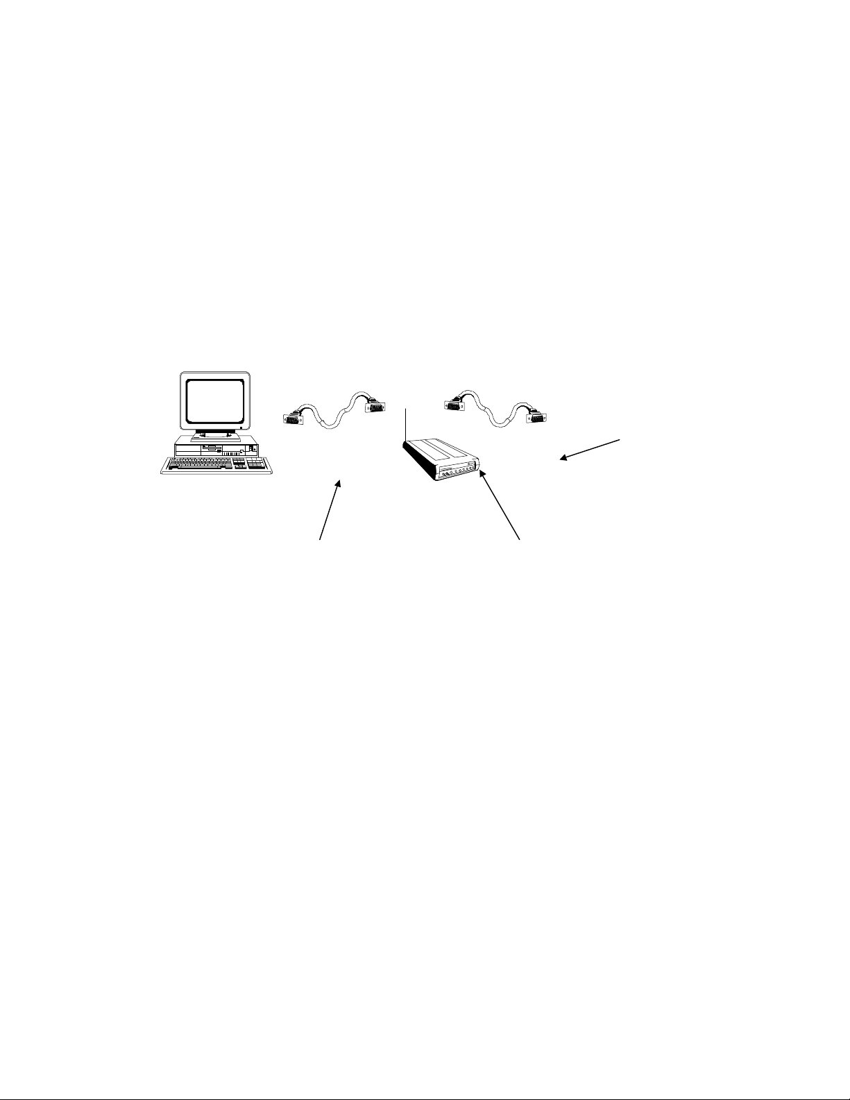
4.0 Hardware Installation (Cabling)
Installing a WINC 2400C involves a simple cable connection between it and a synchronous data device.
However, beffore you can make it operational for wireless data transmission among various units of
WINC 2400Cs, each unit has to be properly configurated. The configuratiion of each unit requires the
connection with a PC or a termainal. (After the configuration task is completed, the PC or terminal can
either stay connected for monitoring purpose or be disconnected). The following instructions are provided
to assist you in wiring peier to the configuration.
1. Turn your computer off before starting.
2. Connect the asynchronous configuration port of the WINC 2400C to your computer's
serial port using an RS-232, DB-9 connector and associated cable.
DB-25 or V.35 connector to
external device
Cable with DB-9 connectors at each end
connect Async. port of WINC 2400C and PC.
Fig. 4.0 Wiring Interface
DB-25 male connector connects to WINC
2400C DB-25 female Sync. Port
3. The DB-25 connector of WINC 2400C is used to connect to a synchronous device like a digital
multiplexer or LAN bridge. This DB-25 port can be configured as RS-23, V.35, or RS-422 by
configuration software. Please refer to Appendix C for detailed pin definition for different interfaces.
4. Attach the rubber omni antenna to the matching connector on the rear of the WINC 2400C.
5. With the WINC 2400C power switch in the off position, connect the power cord to the rear of the unit
and plug it into the electrical jack nearest your equipment. The WINC 2400C is equipped with a
universal power supply for 110-220 volts and will internally adjust itself for either voltage.
6. Turn on the computer and the synchronous device, if applicable.
7. Turn on the WINC 2400C modem. The WINC 2400C performs a brief self-test. LED indicator
lights will be displayed on the front panel. Each LED displays single or dual colors. Green indicates
an active state or signal presence, whereas red indicates otherwise. See Appendix C, WINC 2400C
Synchronous Interface Status, for LED indicator definitions.
8
Page 9

After the self-test, you are now ready to do the configuration. This will be presented in the next section..
9
Page 10

5.0 System Configuration
Before we proceed from here, let us back off a little bit. Although the WINC 2400C is a modem with a
wireless transceiver, it has been designed to be compatible with off-the-shelf commercially available
communications software typically used with conventional land-line modems. Consequently, we take for
grated that you already have the software to operate a land line modem in place, such as the PC
communications software Pcplus. Otherwise, you have to install the appropriate data communications
software into your computer before proceeding the configuration.
We now proceed to the configuration. There are two parts. The first part involves the enabling of PC or
terminal to communicate with the WINC 2400C. This can be achieved in 4 steps to be described below.
The next part is the concept of synchronous software configuration to be presented in section 5.1.
Please note, due to the popularity of MS-Windows, the Terminal in the Accessories of MS
Window 3.1 will be used in the following process as guidance.
Step 1: Activate your communication software
a. Running MS-Windows, and then activate the Terminal in Accessories.
b. Click the “Settings” ,and then activate the “Communications” dialog box.
Step 2: Configure your communication software to meet default value of configuration port on the WINC
2400C
a. Click on the available serial port from the “Connector” list,
b. Click on the 9600 from the “Baud Rate” list,
c. Click on “OK” return to the Terminal.
All selectable items in the communication dialog box will turn into active (high-lighted), if the
selected serial port is available on your computer. Otherwise, stop here and consult with a
computer set up specialist about setting up serial port for you.
Step 3: Communicate with WINC 2400C via AT command
a. Press the “Enter” key.
You should get an “ERROR” whenever you press the Enter key without AT commands.
b. Try type in “ATI0”
You should get response similar to the followings:
MODEM address: 2500155
Peer address : 3467777
Current channel: 0
(The MODEM address should match the right-most seven (7) digits of the serial number digit
found on the label affixed to the left side of the unit.)
After the configuration setup process above, the communications software will go into the localterminal or direct-connection mode. All AT commands for WINC 2400C will be sent to the
serial port directly, accepted and executed by WINC 2400C.
There is a possibility that you will get some funny characters or no response resulting from the
different baud rate settings on the communications software and the WINC 2400C. If this
happens, please reset the WINC 2400C back to the manufacturer’s default setting -- 9600 bps as
instructed below.
10
Page 11
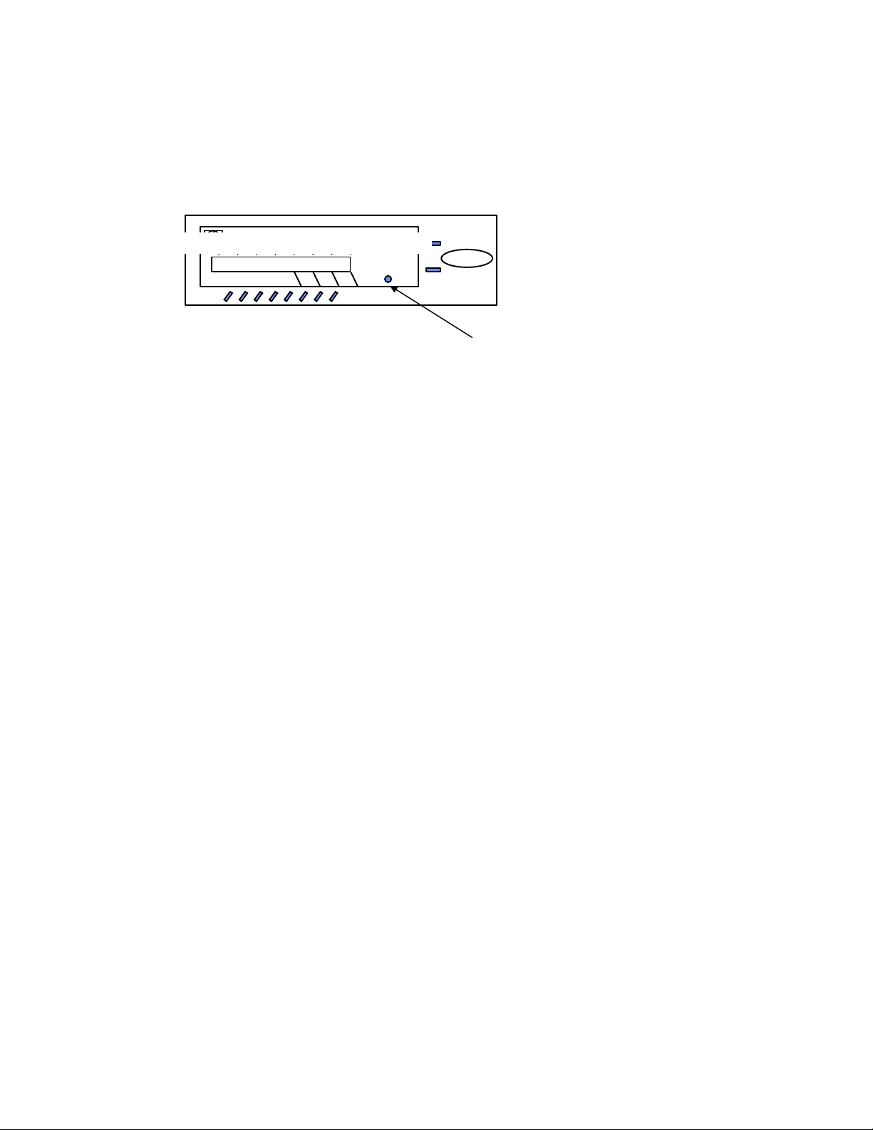
Whenever you need to clear the settings, you can issue AT command AT&F to reset the WINC
2400C to the original factory default conditions. An alternative method for accomplishing this is
to hold the reset button on the front panel and turn on the power of WINC 2400C. (please refer
to Fig. 5 -1) A pencil, pen or other sharply pointed object is required to access the button
through the hole on the front panel.
Teletronics Wireless Modem
Fig 5-1. WINC 2400C Front Panel
DCD
DTR
DSR
CTS
RTS
LINK
RTS
RxD
RxD
FULL DUPLEX INTERFACE
TxD
SYNC. PORT
TxD
Power
Default
Winc 900CASYNC. PORT
Step 4: Save the configuration settings
of your communications of software
If you already completed the steps above without problems, you may select the “Save” from the
“File” option in the MS-Windows Terminal and save the configuration settings for the future
before you leave Terminal.
If you still have problems communicating with the WINC 2400C from your computer, please check the
followings steps, and then start all over again from the beginning of this chapter.
1. Contact your computer hardware engineer, verify the availability of the serial port (com port) on
your computer, and working on this until the serial port is available to you.
2. Connect your serial port with an external land line modem and work on the communication software
setting until you get the dial tone, dialing out successfully.
3. Replace the external modem with WINC 2400C. At this point, go through the factory default
setting process above to make sure that 9600 is the default baud rate on WINC 2400C.
4. Please work from the beginning of chapter 4.0 again.
5. If you still have problems communicating with the WINC 2400C, Please visit our Web Customer
Support page at www.teletronics.com or fill out the technical support request form at the last
page with all details and fax it to our “Technical Support Team” located in our US headquarters.
5.1 The Concept of Synchronous Configuration
After we have achieved the part I of the system configuration, we now move part II. Let us start with a
point-to-point link where two WINC 2400C are involved. Major technical
details are :
1. The Baud Rate setting of the external device.
2. Make sure that all external devices are configured as DTE and does take Tx and Rx clock from
external device -- WINC 2400C for better performance.
3. The interface configuration on the external device -- RS-232, RS-422, or V.35.
4. The frequency interference, LOS (line of sight) at both locations.
5. The address of both WINC 2400Cs.
(The seven (7) digit address is on the label affixed to the left side of the unit and is defined by the rightmost seven (7) digits of the serial number).
The configuration process is mainly a process of setting up parameters so that link can be maintained at
both WINC 2400Cs. Consistency includes the following.
11
Page 12

1. Baud Rate
2. Your choice of interface type on both WINC 2400Cs must match to the interface type of external
device.
3. Regarding the setting of Tx and Tx clock source, we prefer to choose INTERNAL on both selections.
4. Peer address on both units must cross indexed each other.
5. The choice of channel must be the same.
6. Our recommendation on SYNC protocol is “TRANSPARENT”.
7. The unit closes to the control center should be designated as “MASTER” unit. And, the remote unit
should be “SLAVE” unit.
8. Your choice on Air Preamble pattern must be the same on both units.
9. Your choice on Air Spreading Code pattern of both units must be the same.
Please note, the configuration process should be performed with one WINC 2400C at a time.
Otherwise, you might not be able to complete the configuration process before the connection process
between these two units. (Please refer to Appendix A for details)
After the configuration process, a wireless linkage between the local and remote WINC 2400C can be
established on the designated channel. However, if this channel is not performing properly, or if for some
other reason you wish to switch to another channel, you must make the changes on both WINC 2400Cs.
The change again has to be made from the PC or the termainal.
The actual procedure of configuration is performed by selecting alternatives from a series of menus via the
DB-9 configuration port. In this section the menu selection procedure is detailed.
The Main Menu is selected by issuing the AT command <AT> from the terminal connected to the
asynchronous port. On issuing this command, the main menu appears on the screen and contains seven
(7) alternative selections as follows:
(1) Change Active Operating Mode,
(2) Configure Synchronous Interface
(3) Configure Asynchronous Interface
(4) Configure Broadcast Interface
(5) Air Link Status,
(6) System Reset
(7) Exit.
(Please Note, option 3, Configure Asynchronous Interface, is not active in WINC 2400C, so just ignore
the option.)
Selections 1, 2, and 4 are crucial when you wish to change or modify either the synchronous, or broadcast
operation of the system. The Menu Selection Procedure in the following outlines the recommended
approach for configuring the system. As indicated, you must first determine which mode the system is in
before re-configuring. Once that is determined, it is a simple matter to follow the procedure as outlined.
Main Menu Selections
(1) Change Active Operating Mode:
This option is designed to change the operating mode from asynchronous to synchronous or vice
versa. Since the current WINC 2400C operates always at the synchronous mode, you should choose
option 1 to change to synchronous operation, if it is not already set that way. Then choose (7) Exit
to get back to the Main Menu. When in the Main Menu choose (6) to reset the system to the
operating mode chosen.
12
Page 13

(2) Configure Synchronous Interface:
Select this option from the Main Menu to configure the synchronous interface.
(3) Configure Asynchronous Interface:
Select this option from the Main Menu to configure the asynchronous interface. (Please note : The
choices under this menu selection will be removed from WINC 2400C model, if not yet on the
screen).
(4) Configure Broadcast Interface:
Select this option from the Main Menu to change the parameters for broadcast mode. The choices
under this menu selection are described in Section 5.4.
(5) Air-Link Status:
Select this option to determine the air-link performance statistics.
(6) System Reset:
Select this option when it is required to reset the system to effect the change selected previously. The
changes that require this step are specified in the menu associated with that change. Please note that
the Main Menu is exited upon choosing this option. To get back to the Main Menu you must issue
the <AT> command from the terminal mode.
(7) Exit:
Select this option to exit from the Main Menu.
5.2 Synchronous Configuration
After choosing Configure SYNCHRONOUS interface, you will see the following screen : (please
refer to fig. 5-3 for the layout of configuration manual)
Synchronous Configuration
Current speed : 64000 Interface type : RS-232
Tx clock source : INTERNAL Rx clock source : INTERNAL
Peer Address : XXXXXXX Active Channel : 0
Self Address : XXXXXXX SYNC Protocol : TRANSPARENT
FEC Er Drop Pkt : OFF Master-Slave : SLAVE
Air Time-Out : 15 Air Preamble IX : 8
Air Spreading IX : 0 Power Level : 4
1. Change SYNC speed 2. Change interface type
3. Change Tx clock source 4. Change Rx clock source
5. Change Peer Address 6. Change Channel Number
7. Change operation protocol 8. Change power level
9. Change FEC Check Operation
A. Change Master-Slave mode
B. Change air Time-Out value
C. Change air Preamble pattern
D. Change air Spreading Code pattern
E. Back to previous menu
Enter :
13
Page 14

Exit
EXIT
Pattern
(31 chips)
Spreading Code
0
1
11-chips
1
2
2
4
3
5
6
7
EXIT
3
4
5
6
7
8
9
101112
Main
Menu
<AT>
Status
Air-Link
System Reset
Interface
Configure
Asynchronous
Interface
Configure
Synchronous
Pattern
(31 chips)
Preamble Code
Operation
Master/Slave
Protocol
Synchronous
Peer
Address
1020304050
(sec)
Value
Link Time-Out
FEC
Operation
Select
(MHz)
Channel
MSTR
ON
TRANS
0-2404
INT
1-2408
SLAVE
OFF
HDLC
2-2412
3-2416
<ENTER>
EXT
60
EXIT
EXIT
EXIT
4-2420
EXIT
EXIT
120
5-2424
180
131415
EXIT
EXIT
Source
Rx Clock
INT
Source
Change Active
Operating Mode
Exit
async to sync
sync to async
Tx Clock
(kbps)
Data Rate
Synchronous
9.6
Type
Interface
19.2
38.4
56.0
RS-232
57.6
64.0
Fig. 5.3 Layout of Synchronous Configuration Manual
14
EXT
V.35
72.0
96.0
EXIT
RS-422
128
EXIT
EXIT
Page 15

(1) Change SYNC speed:
This selection determines the data rate in Kbps of data entering and leaving the WINC 2400C over
the synchronous port. The data rate ranges from 9600 bps to 128 Kbps. Please note that once the
selection is made, it takes effect instantly. In addition, this selection is only valid when the WINC
2400C provides the clock, i.e., items 3 and 4 setting are at internal.
(2) Change interface type:
Three types of physical interfaces, RS-232, V.35 or RS-422, are available for synchronous operation.
This selection allows the user to choose from the list.
(3) Change Tx (Transmit) clock source:
This selection determines whether the WINC 2400C (considered the DCE) provides the transmit
clock (internal) to the DTE or receives the transmit clock (external) from the DTE . The choice of
internal is recommended.
(4) Change Rx (Receive) clock source:
This selection determines whether the WINC 2400C (considered the DCE) provides the receive clock
(internal) to the DTE or receives the receive clock (external) from the DTE. Again, the choice of
internal is recommended
(5) Change Peer Address:
This 7-digit number represents the address of the modem in remote to which a link is established.
The address is on the sticker attached to the side of the remote unit.
(6) Change Channel Number:
Operating in the synchronous mode, twenty (20) 4-MHz channels are available for communications.
After you make your selection, you must coordinate that choice with the distant end and use this menu
to select the idential channel.
(7) Change operation protocol:
This selection determines whether the synchronous interface between the DTE and the WINC 2400C
(DCE) is transparent (i.e. no meaning is associated with any bit or bit sequence) or HDLC (i.e. a
“bit-oriented” protocol in which data bits are “framed” by standardized bit sequences). For proper
operation the DTE and the DCE should be configured identically. Note that the system must be reset
for this change to take effect. We recommend transparent.
(8) Change power level:
Using this selection you can choose any one of four transmission power levels, if available.
Otherwise, the selection is not operative.
(9) Change FEC Check Operation:
When operating synchronously, forward error correction (FEC) is used to improve the link
performance. This selection determines whether only error-free packets are passed to the DTE (FEC
ON) or whether all packets are passed (FEC OFF), i.e. even those packets with known errors are
passed to the DTE.
(A) Change Master - Slave mode:
For proper operation of the system, one unit must be designated as the master unit and the other as
the slave. This selection is used to make such a designation. Note that the system must be reset
before this instruction takes effect.
(B) Change air Time-Out value:
15
Page 16

This value determines how long the link remains established without receiving the handshake control
packet.
(C) Change air Preamble pattern:
The WINC 2400C uses separate spreading code sequences for synchronization and communications.
The preamble is used for synchronization and consists of 16-code patterns, each 63 chips in length.
This selection allows one of those patterns to be chosen. Note that the system must be reset before a
new pattern takes effect and both the local and distant terminals must use the same code pattern.
(D) Change air Spreading Code pattern:
The spreading code used for communications can be either 11 chips or 31 chips in length. This
selection allows either one 11-chip code or one of nine 31-chip codes to be chosen. As above, the
system must be reset before this selection takes effect and the same code must be selected by both the
local and distant end. Please consult Teletronics before you intend to make the change.
5.3 Broadcast Configuration
Most of the configuration setting under the broadcast mode are similar to the synchronous mode. The
address configuration is the only difference comparing to the synchronous configuration.
In the broadcast mode, only one station can function as the master station. This master station will
perform the broadcast function sending messages it received from the synchronous device to the air.
The receivers are configured to be at slave mode and their master address in the configuration setting has
to be set to the master station’s address. Otherwise the slave station can not filter the transmitted
message from master station. This master address and broadcast address can be changed as shown under
item 5 below.
(1) Change SYNC speed:
This selection determines the data rate in Kbps of data entering and leaving the WINC 2400C over
the synchronous port. The data rate ranges from 9600 bps to 128 Kbps. Please note that once the
selection is made, it takes effect instantly. In addition, this selection is only valid when the WINC
2400C provides the clock, i.e., items 3 and 4 settings are at internal.
(2) Change interface type:
Three types of physical interfaces, RS-232, V.35, or RS-422, are available for synchronous
operation. This selection allows the user to choose from the list.
(3) Change Tx (Transmit) clock source:
This selection determines whether the WINC 2400C (considered the DCE) provides the transmit
clock (internal) to the DTE or receives the transmit clock (external) from the DTE . The choice of
internal is recommended.
(4) Change Rx (Receive) clock source:
This selection determines whether the WINC 2400C (considered the DCE) provides the receive clock
(internal) to the DTE or receives the receive clock (external) from the DTE. The choice of internal is
recommended.
(5) Broadcast Address / Change Master Address:
If this station is configured as master, this option will be marked as “Broadcast Address” and a
default address -- “9999999” will be assigned automatically after you select this option. Under the
slave configuration setting, “Change Master Address” will be listed as option and the master station
16
Page 17

address should be assigned to this configuration. The address is on the sticker attached to the side of
the MASTER unit.
(6) Change Channel Number:
Operating in the synchronous mode, twenty (20) 4-MHz channels are available for communications.
If, however, you wish to select a specific channel you must coordinate that choice with the distant end
and use this menu to select the desired channel.
(7) Change operation protocol:
This selection determines whether the synchronous interface between the DTE and the WINC 2400C
(DCE) is transparent (i.e. no meaning is associated with any bit or bit sequence) or HDLC (i.e. a
“bit-oriented” protocol in which data bits are “framed” by standardized bit sequences). For proper
operation the DTE and the DCE should be configured identically. Note that the system must be reset
for this change to take effect. We recommend the choice of transparent.
(8) Change power level:
Using this selection you can choose any one of four transmission power levels, if available.
Otherwise, this selection is not operative.
(9) Change FEC Check Operation:
When operating synchronously, forward error correction (FEC) is used to improve the link
performance. This selection determines whether only error-free packets are passed to the DTE (FEC
ON) or whether all packets are passed (FEC OFF), i.e. even those packets with known errors are
passed to the DTE.
(A) Change Master - Slave mode:
For proper operation of the system, the broadcaster must be designated as the master. And, receivers
must be configured as the slave. This selection is used to make such a designation. Note that the
system must be reset before this instruction takes effect.
(B) Change air Time-Out value:
This value determines how long the link remains established without receiving the handshake control
packet.
(C) Change air Preamble pattern:
The WINC 2400C uses separate spreading code sequences for synchronization and communications.
The preamble is used for synchronization and consists of 16-code patterns, each 63 chips in length.
This selection allows one of those patterns to be chosen. Note that the system must be reset before a
new pattern takes effect and both the local and distant terminals must use the same code pattern.
(D) Change air Spreading Code pattern:
The spreading code used for communications can be either 11 chips or 31 chips in length. This
selection allows either one 11-chip code or one of nine 31-chip codes to be chosen. As above, the
system must be reset before this selection takes effect and the same code must be selected by both the
local and distant end. Please consult Teletronics before making the intended change.
17
Page 18

APPENDIX A : AT Command Set
At any given time the WINC 2400C configuration port is in the command mode. The configuration
port accepts AT commands from the host computer connected to that port. These commands are sent
to the WINC 2400C as character strings composed of printable ASCII characters. Using the same
character set, the WINC 2400C responds to the host computer's command by sending back a result
code string indicating whether the WINC 2400C was able to accomplish the requested command.
The command language is simulated to the Hayes compatible and de facto industry standard AT
command set. In addition to the basic AT commands, certain command extensions accommodate
specific WINC 2400C configuration requirements.
AT Command Syntax
A command line is a string of characters sent from the host computer or peripheral - Data Terminal
Equipment (DTE), to the WINC 2400C - Data Communications Equipment (DCE). (The command
line is interpreted by the DCE only when in the command state.) All command lines have a prefix, a
body, and a terminator. The prefix consists of the characters "AT" and the body is a command string
restricted to the printable ASCII characters. The default terminator is the <CR> character and is
required for all commands.
Commonly used AT Commands with the WINC 2400C
Viewing the Current Connection Status
The current connection status of the WINC 2400C can be viewed at any time by using the AT&&
command. In response to this command, the connection status of WINC 2400C will be displayed as
following.
Global counters:
Air_rx_pkt = 0 Air_tx_pkt = 0
Air_rx_data = 0 Air_tx_data = 0
Async_rx_pkt = 19 Async_tx_pkt = 27
Sync_rx_pkt = 0 Sync_tx_pkt = 0
Air_CRC_Err = 0
Air_Drr = 0
Air_State = OUT_OF_SYNC
Air_Tx_Backoff = 0
Air_Rx_Len_Err = 0
Sync_Port_Speed = 64000
SYNC_Port_Rx_Err = 0 ASYNC_Flow_Ctrl_Cnt = 0
SYNC_Tx > 64 Byte = 0 SYNC (>64 Pkt) lost = 0
SYNC_Rx >1024 Cnt = 0 SYNC_Tx > 1024 Cnt = 0
SYNC_Use_Fake_Buf = 0 Air_Use_Fake_Buf = 0
Preamble_code_inx = 8 Preamble_threshold = 5
Spread_Code_Inx = 0 Async_flow_cntl = 2
bufque_put = 38 bufque_get = 57
power level = 4 (AUTO) Channel = 0 Air_Bsy_Cnt = 0
module_availq = 41
18
Page 19

Current active port: SYNC
0 0 0 0 0 0 0 0 0 || 0 0 0 0 0 0 0 0
Verifying the Local Address
Each WINC 2400C has been identified at the factory with a unique address (identical to the serial
number listed on the label on the left-hand side of the unit)2. For a remote terminal, this represents
the destination address. The local address can be verified using the ATI command, where ATI0
refers to the equipment identification number or local address. Please refer to the following table for
more details about ATI commands:
ATI COMMANDS SYSTEM RESPONSES
ATI0 MODEM address: 2500155
Peer address : 3467777
Current channel: 0
ATI1 Release version: 1.15
ATI2 MODEM Manufacture: Teletronics International Inc.
ATI3 Model: WINC-2400C-SYNC128
ATI4 Current Crystal Type: 16.384M
19
Page 20

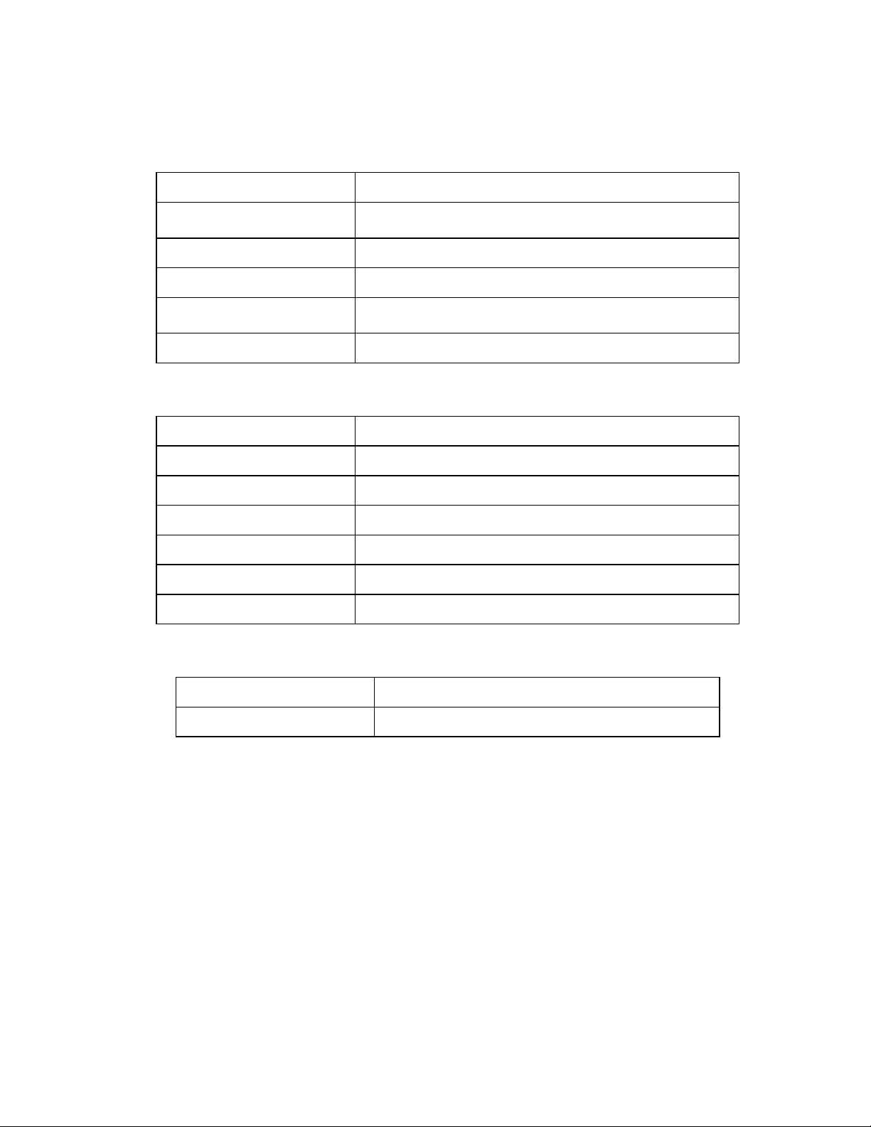
APPENDIX B : WINC 2400C Interface Status
The WINC 2400C interface status refers to the state of the RS-232 serial ports between the local
terminal or computer and the WINC 2400C. The state, in turn, is determined by the signal levels on
each of the signal lines that comprise that serial port. These status lines have been brought to the
front panel in the form of two sets of light emitting diodes (LED). The lower set refers to the
synchronous port and the upper set refers to the asynchronous port. A default button has been
provided to the right of this series of LEDs and if this button is depressed when the system is
powered ON, the unit will return to the default state.
To the right of the default button are two additional indicators, one above the other and each
rectangularity shaped. When the unit is powered ON, the upper indicator turns red and stays red until
the unit is powered down. The lower indicator provides a measure of the receive signal strength.
When the indicator is green, the receive signal on the current channel is sufficiently strong to
maintain a connection with the remote terminal. A weak signal will cause the indicator to turn off.
Each LED displays one of two different colors, green or red. Green indicates an active state or signal
presence, whereas red indicates an inactive state or signal absence. The configuration of the two
rows of LEDs is shown above and the table below indicates the function of each signal beginning
with the left most indicator.
Asynchronous Interface
Panel L E D Function
Data Carrier Detect (DCD) Indicates "connection established" with remote.
Data Terminal Ready (DTR) Signal from host (DTE) to device (DCE). May indicate
command mode escape or ignored by device.
Data Set Ready (DSR) Signal from device to host. May indicate connection
established or always on.
Clear To Send (CTS) Indicates device ready to accept data from host. Used in H/W
flow control.
Request To Send (RTS) Indicates host ready to send data to device. Used in H/W flow
control.
Receive Data (RxD) Serial data input to DTE from modem.
Transmit Data (TxD) Serial data input to modem from DTE.
Default Reset Button Reset device to factory defaults.
When the WINC 2400C is initially powered up the CTS and DSR indicators should be green,
whereas the RI and DCD indicators are red.
Once the connection is established, the DCD indicator turns green.
If the port is configured to use hardware flow control the CTS indicator will change to RED when the
WINC's internal buffer becomes full. When data is removed from the buffer the CTS indicator will
turn green again.
When a connection request from a remote terminal is received the RI turns green. It will turn red
when the connection is established or the connection request has timed out.
20
Page 21

The DTR, DSR, RTS, and CTS indicators follow the AT configuration commands as issued to the
WINC 2400C. For example, if the device has been configured for S/W flow control then the RTS
and CTS indicators will be red.
Since the WINC 2400C alternatively transmits and receives when online, the TXD and RXD
indicators cycle between green and red at the configured data rate.
When the default reset button is pressed while powering ON the unit, the asynchronous port of the
WINC 2400C defaults to the factory preset configuration of 9600 bps, 8 bits per character, no parity,
1 start bit, 1 stop bit, hardware flow control, and auto answer. Similarly, the synchronous port
defaults to Powering ON the unit without depressing the default button resets to their previously
configured state. To ensure that the unit resets to the default conditions, first power down the unit
and then power it on while depressing the default button.
To the right of the serial line LEDs are two small rectangular LED indicators. The lower green
indicator lights when the power is on, while the upper red LED indicates the receive signal level.
Solid ON indicates sufficient signal strength, while solid OFF indicates either no received signal or a
signal too weak to sustain communications. A blinking signal indicates a marginal signal level.
If you experience difficulty in establishing connections between a local and remote WINC 2400C,
first reset both units to the factory default conditions and retry before calling for technical assistance.
Synchronous Interface
For the synchronous interface, only the LEDs representing the state of the transmit and receive data
across the interface are meaningful. These are represented are the two right-most LEDs in the lower
row designated as TxD and RxD, respectively. In addition the left-most LED indicates the state of
the air-link. A solid light indicates that the link is established and when dark it indicates that he link
is down. All other LEDs in that row should be ignored.
Panel L E D Function
Air-link Indicates that the air-link is established.
Data Carrier Detect (DCD) Not applicable.
Data Terminal Ready (DTR) Not applicable.
Data Set Ready (DSR) Not applicable.
Clear To Send (CTS) Not applicable.
Request To Send (RTS) Not applicable.
Receive Data (RxD) Synchronous data input to DTE from modem.
Transmit Data (TxD) Synchronous data input to modem from DTE.
Default Reset Button Reset device to factory defaults.
21
Page 22
APPENDIX C - WINC 2400C Specification
Serial Interface
Async data rates (Kbps) 1.2, 2.4, 4.8, 9.6, 14.4, 19.2, 28.8, 38.4
Async data format Data: 7, 8 bits, Parity: even/odd/none,
Stop bit: 1 or 2
Flow Control XON/XOFF, RTS/CTS
Sync data rates (Kbps) 9.6, 19.2, 38.4, 56.0, 57.6, 64.0, 72.0, 96.0, 128
Connector Port 1: RS-232, DB-25 female (synchronous)
Port 2: RS-232, DB-9 male (asynchronous)
Compatibility Hayes AT Command Set
Radio
Frequency Band 2404-2483 MHz (transmit and receive at ISM band)
Channelization 24 independent @ 4 MHz per channel (sync)
Modulation DQPSK
Spread Spectrum Direct-Sequence
Sensitivity -80dbm (not including spreading gain)
Range 1 kilometer outdoors; 50 meters indoors
Antenna Rubber omnidirectional
Power
Primary Power 100-250 VAC @50/60 Hz, 0.3-0.7A, auto-switching
Internal Power Supply 28 Watts, AC
22
Page 23

APPENDIX D - WINC 2400C Connector Definition
WINC 2400C CONNECTORS
RS-232 Interface
Port 1 (DB25 Female)
Pin
15
17
24
25
Pin
Designation Direction
2
3
7
RXD
TXD
GND
RXC
TXC
ERC
ETC
RS-232 Interface
Port 2 (DB9 Male)
Designation Direction
1
2
3
4
5
6
7
8
DCD
TXD
RXD
DSR
GND
DTR
CTS
RTS
IN
OUT
OUT
OUT
IN
IN
IN
OUT
IN
OUT
IN
OUT
IN
Function
RX Data
TX Data
-
-
Signal Ground
RX Clock
TX Clock
External RX Clock
External TX Clock
Function
Data Carrier Dectect
TX Data
RX Data
Data Set Ready
Signal Ground
Data Terminal Ready
Clear To Send
Ready To Send
Pin
11
12
14
15
16
17
24
25
RS-422 Interface
Port 1 (DB25 Female)
Designation Direction
1
2
3
7
9
ETC+
RXDTXDGND
TXC+
ERC+
RXC+
RXD+
RXCTXD+
TXCERCETC-
IN
IN
OUT
OUT
IN
OUT
IN
OUT
OUT
OUT
IN
IN
Function
External TX Clock (-)
RX Data (-)
TX Data (-)
-
Signal Ground
TX Clock (+)
External RX Clock (+)
RX Clock (+)
RX Data (+)
RX Clock (-)
TX Data (+)
TX Clock (-)
External RX Clock (-)
External TX Clock (-)
23
Page 24

V.35 cable configuration:
The physical interface on WINC900C/2400C is DB-25. For some cases, we need
to make one converted cable to connect to external device. connecting to external
device’s V.35 Winchester type interface, such as interface on RAD Kilomux-2000,
The configuration is as follows:
WINC900C/2400C
( DB-25 Type )
1 TXC(B) (EXT) ß----- Z
2 RXD(A) ß----- P
3 TXD(A) -----à R
4 CTS(A) ß----- C
5 RTS(A) -----à D
6 DTR(A) -----à E
7 GND -------- B
8 DCD(A) -----à F
9 TXC(B) (INT) -----à X
11 RXC(B) (EXT) ß----- W
12 RXC(B) (INT) -----à AA
14 RXD(B) ß----- S
15 RXC(A) (INT) -----à Y
16 TXD(B) -----à T
17 TXC(A) (INT) -----à V
20 DSR(A) ß----- H
24 RXC(A) (EXT) ß----- U
25 TXC(A) (EXT) ß----- BB
Pin Definition
( Function )
Direction RAD Kilomux-2000
( Winchester Type )
The V.35 interface is not directly match to standard specifications. But, it will be OK
to connect to any other V.35 interface device. In our field test, WINC 2400C
connects to the V.35 interface on Kilomux-2000 and 3Com remote bridge interface
directly. It works as we expected.
24
Page 25

Additional Support
Teletronics International, Inc. is pleased to provide software and integration support to customers
desiring to develop special WINC 2400C applications. Teletronics’ personnel will assist you in
developing functional and technical requirements for your specific application and will work with
you in implementing cost effective solutions. Please contact Teletronics directly to discuss your
particular needs.
25
Page 26

26
Page 27

Printed in the USA Teletronics International Inc.
24C0313.doc 1803 Research Blvd, Suite 404
Rockville, MD 20850-3155 USA
27
 Loading...