

Page 1

Warranty Policy
Limited Warranty
1. All Teletronics products have 1 Year Warranty Period. (Except List of Antennas Attached)
2. Our Warranty Period does not cover physical damages, misuse of the product, and natural disasters.
3. International customers have 60 business days return policy, in order to receive full refund for the
items purchased. Only if the item is consider to be brand new unit. (Unopened Items)
4. Domestic customers have 30 business days return policy, in order to receive full refund for the items
purchased. Only if the item is consider to be brand new unit. (Unopened Items)
5. Within the 30/60 business days, for all used items, there will be a restocking fee charge (0-45%).
Depending on the condition of the item. Restocking Fee might vary.
6. All original materials must be returned in good resalable condition.
7. No refund, exchange or full credit will be issued after the 30/60 business day return policy.
8. Out-of Warranty items are repaired or replaced only with the customer’s prior approval. Labor charges
and freight will vary based on the condition of defective item.
9. Advanced Replacement Cases, must be issued within the 1 Year Warranty Period
10. All RMA numbers automatically expire 30 days after date of issuance.
11. Teletronics reserves the right to refuse any RMA shipment that does not come with RMA Case
Number or an invalid RMA Case Number.
TT 2400
IEEE 802.11b/g
Quick Product Guide
Mechanical Specifications:
Chassis Dimension (W x D x L): 200mm x 70mm x 120mm
7.87" x 2.75" x 4.7"
Board Specifications:
Ethernet: 10/100BaseT Ethernet, Auto MDI/MDI-X
Network Architecture Infrastructure: Ad-Hoc, MAC, CSMA/CA
Status Indicators: Power, Wireless LAN, Ethernet LAN, and RSSI
Push Button: Reset to Default Button
Terms & Conditions
1. REPAIR WARRANTY: All warranties are void if Teletronics finds that the product has been abused, physically damaged
or altered in any way without prior written authorization. 2. OUT OF WARRANTY PRODUCT: Out-of-Warranty Products are
repaired only with the customer’s prior approval. For Out-of-Warranty repair charges, please contact us at 301.309.8500
x136 or rma@teletronics.com. 3. PACKAGING: Please clearly mark the RMA number on the outside of the packaging.
Damage or loss of goods during shipment is the sole responsibility of the customer. Product must be returned in original
carton or in packaging of equal or greater quality. 4. RMA NUMBER: Any returned product without a valid RMA number or
no RMA number will be refused and returned to the sender. RMA numbers are only valid for 30 days from the date they
are issued. Please write the RMA number on the box in bold letters using permanent marker on at least two different sides
of the box. 5. PRODUCT: Ship only the product(s) specified on the original RMA request and includes any additional
items. Any additional products will require a new RMA number. 6. SHIPPING COST: The customer is responsible for the
cost of shipment to Teletronics and we will be responsible for the cost of shipment back to the customer. Ship to:
Teletronics International, Inc. 2 Choke Cherry Road, Suite 100 Rockville, MD 20850 USA. 7. SHIPPING METHOD: All the
repaired products will be shipping back to customers via UPS/FedEX Ground service. For International customers via
Economic 8. ADVANCED REPLACEMENT: If you are requesting Advanced Replacement for the defective product, you
must provide us with a valid credit card number as a guarantee. Please Note: Advanced Replacement charges will be
applied to the customer’s credit card, if the defective product is not received by Teletronics within 21 business days.
9. RMA REFUND: Customer is required to provide the original invoice/receipt to request RMA credit.
6 Easy Steps to Receive an RMA Case#
1. Go to: http://www.teletronics.com/RMA.html
2. Download the RMA Form; fill it out the entire fields with the appropriate product information
3. Email the word file to rma@teletronics.com
4. Within 1 Business Day, you will receive an email with the RMA Receipt Confirmation
5. Package the defective unit with the suitable material
6. Identify the outside of the box with the RMA Case # given in the RMA Receipt
7. Ship the package to: Teletronics – RMA Dept 2 Choke Cherry Rd, Suite 100. Rockville, MD – 20850 USA
NOTE: Advanced Replacement Cases must be issued before 4:30pm (Eastern Time),
in order to ship the package the same business day.
*Specifications Subject to Change without Prior Notice!
All Rights Reserved. Copyright 2006 Teletronics International, Inc.
2 Choke Cherry Road, Rockville, MD 20850 Tel: 301.309.8500 Fax: 301.309.8851
Output Power (200mW):
IEEE 802.11b: 23dBm (+/- 1.5dB) @ 1/2/5.5/11Mbps
IEEE 802.11g: 20dBm (+/- 1.5dB) @ 54Mbps
21dBm (+/- 1.5dB) @ 48 Mbps
22dBm (+/- 1.5dB) @ 36 Mbps
23dBm (+/- 1.5dB) @ 6 Mbps
Receiver Sensitivity:
54Mbps @ -72dBm
48Mbps @ -75dBm
36Mbps @ -78dBm
24Mbps @ -82dBm
11Mbps @ -87dBm
5.5Mbps @ ≤ -88dBm
2Mbps @ -90dBm
1Mbps @ -92Bm
RF Channels: Total of 3 Non-Overlapping Channels
Data Security: WPA/WPA2, 64/128 bit WEP
Fully Transparent Bridge: Unlimited MACs
Management: Web and SNMP based Management
DC Power Input: Includes 48VDC Adapter and PoE
Injector with surge protection, IEEE 802.3af compliant
Frequency Band: 2.4 - 2.5GHz (11 Channels)
Operating Environment: -40 °C to + 70 °C
Enclosure: Silver Powder Coated Cast Aluminum
TT™2400 FEATURES
Ultra High 1W/500mW
output power with optional
amplifiers b/g
Web & SNMP based Management
Transparent bridging supports
unlimited MACs
WPA/WPA2 & 64/128 bit WEP
Data Security
5 Ultra-bright LEDs indicating RSSI
Ruggedized Waterproof &
All-Weather Enclosure
Package List
TT™2400 802.11b/g PCBA (1)
1.
IEEE 802.11b/g Mini PCI Card (1)
2.
Power Over Ethernet Injector (1)
3.
48VDC Power Adapter (1)
4.
Ethernet Cable (2)
5.
Waterproof RJ-45 Connector (1)
6.
Mounting Hardware (1)
7.
Quick User Guide
8.
Page 2
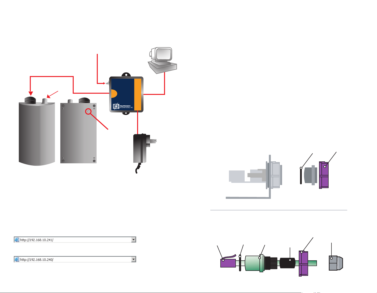
Assembly Instruction
Hardware Installation
I. Assembly Diagram
*Actual parts may vary, please use
this diagram for general guidance.
EXTERNAL ANTENNA
CONNECTOR
TOP VIEW BOTTOM VIEW
CONNECT TO
GROUND
POWER OVER ETHERNET
CONNECTION
PoE
ODU
WITH SURGE
PROTECTION
GROUND
NET
PWR
CONNECTION
TO NETWORK
DC POWER
PC
Follow the procedure below to install your TT™2400 device:
1. Select a suitable place on the network to install the TT™2400. For best wireless reception
and performance the external antenna should be positioned within Line of Sight from the
AP with proper alignment.
2. Connect the TT™2400 to the ODU side of the PoE Injector via a straight Ethernet cable
(Cat-5), then connect the NET side of the PoE Injector to either a computer or an Ethernet Switch.
Note: The TT™2400 now supports MDI/MDI-X and no longer require the use
of cross over cable to connect directly with a computer.
3. Connect the 48VDC power adapter to the power jack on the PoE injector to power on the TT™2400.
Check the LEDs on the TT™2400 to confirm if the status is okay. At this point the PWR and LAN LEDs
should be on green. The WLAN light should light up once the unit is associated wirelessly with another
wireless device. However at this point the unit is still in factory default setting so do not the alarmed
that the WLAN light doesn’t light up.
Waterproof RJ-45
Connector Assembly
NEMA 4 Enclosure
1
2
Quick Installation
Always double check for any missing parts before deployment. Next step is to set up the
computer Ethernet interface for configuring the TT™2400. Since the default IP Address of the
unit is on the 192.168.10.x IP range in both Client Bridge and AP mode you’ll need to set
the computer Ethernet interface within the same IP subnet, such as 192.168.10.66.
Web Control Interface
Default IP Address in Client Bridge Mode (SU): 192.168.10.241
Default IP Address in Access Point Mode (AP): 192.168.10.240
Default Login/Password: Nothing needs to be typed in for login and password authentication.
For detailed instructions on how to configure the TT™2400, please refer
to www.teletronics.com/Support.html
Safety Cap
Re-using items (1) and (2) from the safety cap, assemble the waterproof RJ-45
connector as shown below:
2
3
1
4
5
6
 Loading...