

Page 1
Bandwidth Controller
1
TBC-
800
Version 1.0.2
Copyright 2006 Teletronics International, Inc.
2 Choke Cherry Road
Rockville, MD 20850
Page 2

Table of Contents
Overview and Features ………………….………..…………………………… 3
Structure of Bandwidth Control …………….…………………………………4
Installation ……………………………………………………………………… 4
Network Installation Diagram …................…………………………………….5
Web Configuration Interface ………………………………………………….. 6
Login ………………………………………………………………..…… 6
System Overview ………………………………………………...……… 6
Network Settings ………………………………………………..………. 7
Administration …………………………………………………..………. 9
Services ………………………………………………………..………. 13
Bandwidth Control ……………………..……………………………… 14
Status …………………………………..………………………………. 18
Save & Reboot ………………………..……………………………….. 20
Console / COM Port Configuration …………………………...…………….. 21
Configuration Examples ……………………………………………………… 24
Product Specifications ………………………………………………………... 25
RMA Guidelines ………………………………………………………………. 27
2
Page 3

Overview and Features
3
TBC (Teletronics Bandwidth Controller) is a low-cost, versatile and easy to operate
device specifically designed for network service providers or enterprise customers to
provide a consistent bandwidth flow to the end stations. TBC system automatically shape
TCP/UDP traffic based on built-in rules.
TBC system is simple and reliable allowing network operators to quickly and easily bring
network traffic into balance without changing the existing network infrastructure.
Scalable:
• Create and manage up to 64 Groups
• Each group can have up to 256 Leaf Class/Sessions
Bandwidth Shape:
• Limit Upload/Download speed for every group and leaf class
• Shape Bandwidth by IP address, Subnet, Group, Mac Address and Port
• Ability to apply single or multi-filters for each class
• Prioritize and reserve bandwidth for certain traffic like VoIP and Webcast
Manageable:
• Web Based Management Tool
• Varies Interface: HTTP/HTTPS/Telnet/Serial Console Port
• Compact or Detail Syslog
Network Function:
• DHCP Server
• SNMP
• Remote Syslog
• Utilities: Ping, Trace Route, Tcpdump, NetPerf
Security:
• Admin Configuration with Password
• Restriction access by IP address filtering
• VPN (IPSec/PPTP) pass through
Mounting:
• Desktop
• Wall Mount
• Rack Mount (available later this year)
Page 4

Structure of Bandwidth Control
4
ROOT CLASS
LEAF
CLASS
GROUP
CLASS 2
LEAF
CLASS
LEAF
CLASS
GROUP
CLASS 1
LEAF
CLASS
USING ROOT CONFIGURATION PAGE TO SETUP ROOT CLASS AND DEFAULT RATE.
USING PRIMARY GROUP PAGE TO DEFINE GROUP CLASS.
USING QoS SETTING PAGE TO DEFINE LEAF CLASS.
LEAF
CLASS
LEAF
CLASS
DEFAULT RATE
LEAF
CLASS
LEAF
CLASS
Figure 1
Installation
TBC should be installed between end users and router/ gateway to optimize the
performance and efficiency. This product is a hardware version, so it can be installed on
any traffic you would like to shape. Because TBC is in Bridge Mode, it can shape
bandwidth between different Subnet/IP as well.
TBC has one WAN port, and three LAN port. WAN interface should connect to
router/gateway of DSL, T1, or any internet connection. LAN interface should be
connecting to internal network directly or through a switch/hub.
Steps:
Set your computer's IP Address to 192.168.1.100 with Subnet Mask: 255.255.255.0 (or
any available IP address in
LAN1 port to your computer's Ethernet
For more information about configuration and operation, please see Web Configuration
Interface section. Please see the next page for Installation Diagram (Figure 2).
the 192.168.1.x subnet). Use a crossover cable to connect the
port. Connect power adapter to T
BC-800.
Page 5

Network Installation Diagram
5
SHAPING BASE ON IP
CLIENT #1
SCENARIO 1
CLIENT #2
CLIENTS
BASE STATION
BASE #1
BASE #2 (PLEASE NOTE: IF MORE THAN 3 BASE STATIONS,
TBC ROUTER INTERNET
SCENARIO 2
TBC
YOU WOULD NEED TO ADD A HUB IN BETWEEN)
ROUTER INTERNET
SCENARIO 3
192.168.1.X
SUBNET #1
SUB1
H
U
TBC
SUBNET #2
192.168.10.X
Figure 2
B
ROUTER
SUB2
INTERNET
Page 6
Web Configuration Interface
6
Login
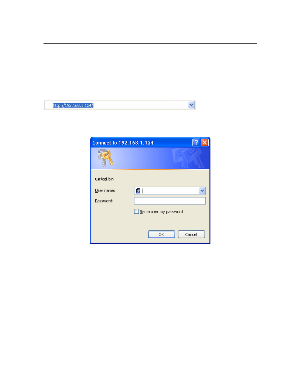
Default IP Address: 192.168.1.124
To access the web control interface, open up a web browser and type in the factory
default IP address in the URL.
Then press Enter on your keyboard, you will see the login prompt window appear.
Default User Name: admin
Default Password: admin
Enter User name and password, and click OK.
Note: You may set a new password by clicking the Administration-Password tab after you
successfully login to the web page.
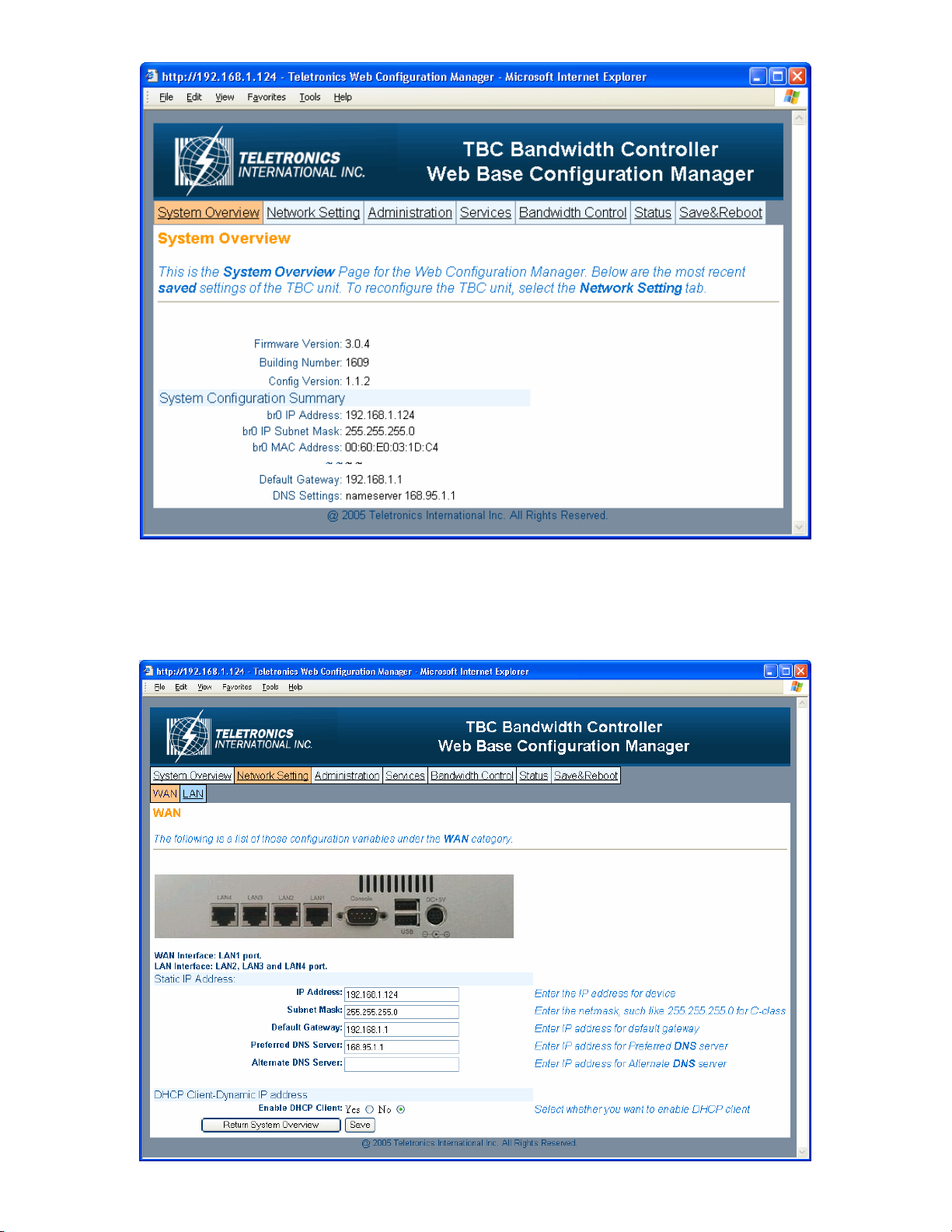
System Overview
This is the main web interface home page. It displays Firmware Version and IP
properties.
Page 7
Network Setting
- WAN
7
Page 8
Static IP Address:
8
Manually setup an IP for this device
• IP Address
• Subnet Mask
• Default Gateway
• Preferred DNS Server
• Alternate DNS Server
DHCP Client:
Set up the device as a DHCP client which will pick up an IP from a DHCP server
Click Save to store the setting
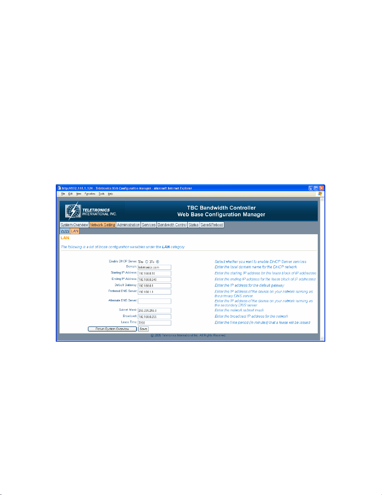
- LAN
TBC can be setup as a DHCP server for the LAN network.
Enable DHCP Server:
• Enable DHCP Server: select Yes
• Domain: Enter the name of the LAN network domain
• Starting & Ending IP Address: Enter the starting and the ending IP address
dynamically assigning to DHCP clients.
• Default Gateway: Enter the LAN network gateway IP address
• Preferred & Alternate DNS Server: Enter the preferred & alternate Domain Name
Server’s IP address
• Subnet Mask: Enter the LAN network subnet
Page 9
• Broadcast: Enter the LAN network Broadcast IP address
9
• Lease Time: Enter the time period (in minute) that a lease will be issued
Click Save to store the setting
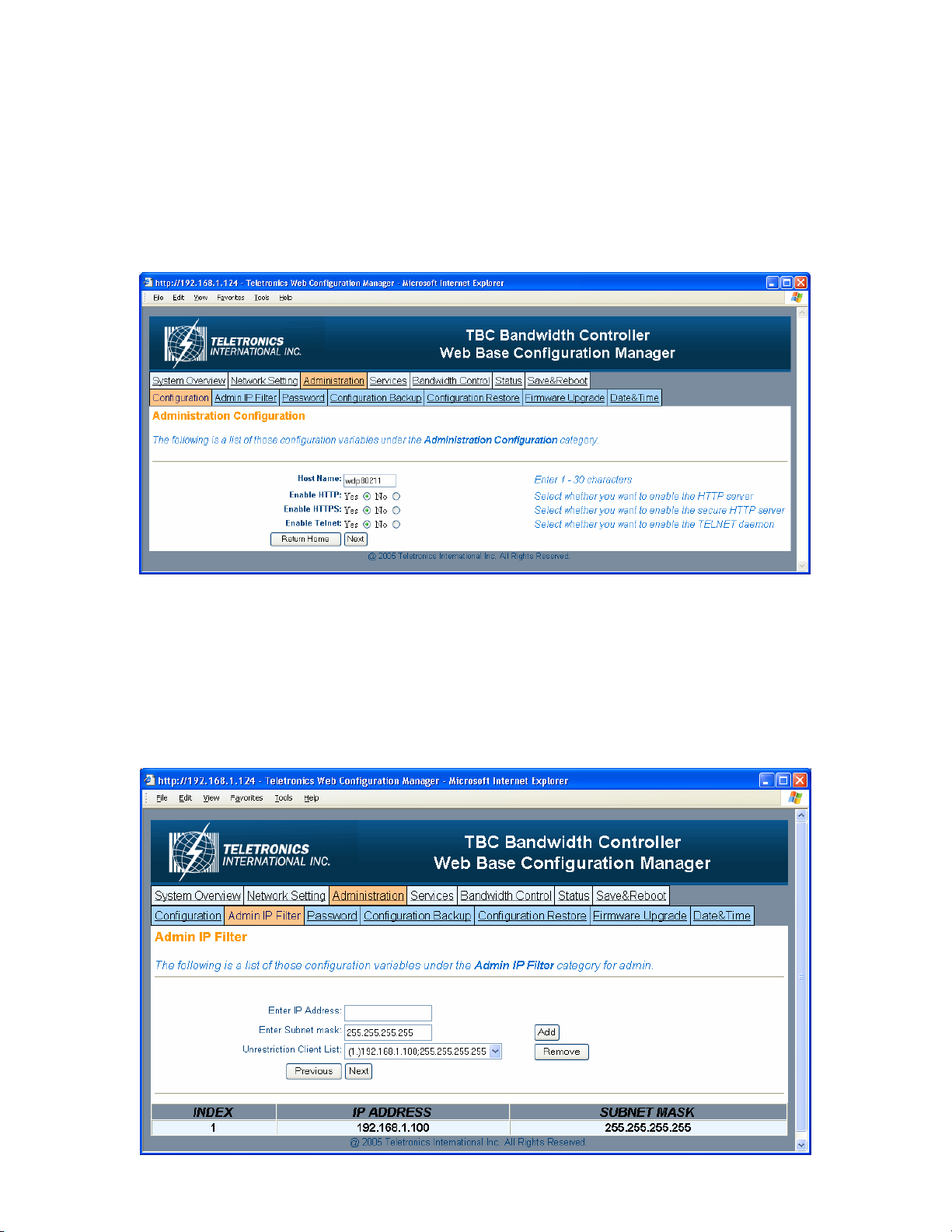
Administration
- Configuration
• Host Name: This is the name for this device. Host name can help to identify the
location if there is more then one bandwidth controller in the LAN network.
• Enable HTTP: HTTP is enable by default
• Enable HTTPS: HTTPS is enable by default
• Enable Telnet: Telnet is enable by default
- Admin IP Filter
Page 10

• Enter IP Address: Enter IP address that will have permission to access this device
10
• Enter Subnet Mask: Enter Subnet Mask to grant permission to a whole or part of
subnet. For example: if enter IP: 192.168.1.100 & subnet: 255.255.255.0, any
address at 192.168.1.x network can access this device.
Click Add or Remove to modify the Admin IP access list.
- Password
You can reset password for user admin. You must enter the same password twice for
confirmation. Click Next to Save, then click Commit Changes to permanently apply the
change.
- Configuration Backup
Page 11

You can save the system configuration file which store user ID, password, device IP
11
address, bandwidth control setting. By clicking Click Here, it will prompt you to save a
tar file as backup.
- Configuration Restore
This section allows the bandwidth controller to restore default factory settings by clicking
Factory Defaults, or to restore from a backup configuration file (the .tar file) to a previous
setting point by clicking From Backup File.
- Firmware Upgrade
This section allows the bandwidth controller firmware to be upgrade or changed. There
are two options to update firmware, update a file direct from a host machine or download
from http or ftp site.
Page 12

• Upload via web browser: Select this option and click Next. Click on the Browse
12
to select the upgrade firmware file and click Upload file to upgrade.
• Download from http or ftp URL: Select this option to download and upgrade the
firmware from a specific URL.
- Date & Time
• Time Zone: Set the Time Zone
• Current System Date: Set System Date with yyyy/mm/dd format
• Current System Time: Set System Time with hh/mm/ss format
• NTP Enable: Enable or disable Network Time Protocol. NTP is used to
synchronize the time.
• NTP Server: If you enable NTP, bandwidth controller will need a NTP server to
request precise time.
Page 13

Services
- SNMP
• SNMP Agent Enable: Option to enable or disable SNMP support
• Read Only Community: The SNMP Read-only Community string is like a user
id or password that allows access to a router's or other device's statistics.
InterMapper sends the community string along with all SNMP requests. If the
community string is correct, the device responds with the requested information.
If the community string is incorrect, the device simply discards the request and
does not respond.
Factory default setting for the read-only community string is set to "public". It is
standard practice to change all the community strings so that outsiders cannot see
information about the internal network. (In addition, the administrator may also
employ firewalls to block any SNMP traffic to ports 161 and 162 on the internal
network.)
Change this value to have InterMapper use the new string when querying SNMP
devices.
• Read Write Community: allows a remote device to read information from a
device and to modify settings on that device. InterMapper does not use the readwrite community string, since it never attempts to modify any settings on its
devices.
• SNMP Sys Contact: Enter email address to contact support
• SNMP Sys Location: Enter system location
13
Page 14

- Remote Syslog
• Syslog Remote Enable: Option to enable or disable Remote Syslog
• Syslog Server: Enter remote Syslog server IP address
Bandwidth Control
- Root Configuration
Bandwidth Control Root Configuration page allows administrator to set Root Class and
Default Bandwidth Rate for both Upload and Download.
14
Page 15

• Bandwidth Control: Options to enable or disable Bandwidth Control. Default
setting is set to Disable
• Firewall Filter: Options to enable or disable Firewall Filter. If enabled, only
those IP address defined in QoS list can pass through the device.
• Default Upload Rate: Enter Default Maximum Upload Rate
• Default Download Rate: Enter Default Maximum Download Rate
Any traffic is not defined in the bandwidth control list/group will use this default upload
and download rate.
Click Next to save and continue.
- Primary Group
Primary Group Page allows administrator to create new group. After each group is
created, the group name will be displayed under Index Table. Each group should be
assigned a unique Group ID Number.
• Group Name: Name of the group you want to create. Group name will help
identifying different type of clients/customers
• Group ID: A unique group number assign for each group, must be between 2-
200
• Upload Rate: Upload rate for each specific group
• Download Rate: Download rate for each specific group
• Group List: This is for Modify and Remove purpose.
15
Page 16

To Add a Group
Enter Group Name, Group ID, Upload & Download Rate
Click Add to create a group
To Remove a Group
Select a group you want to remove from Group List
Click Remove to delete
To Modify an existing Group
Under Group List, select the group you want to modify. Enter the new value for Group
Name. Group ID, and Upload/Download Rate, or enter the same value if it’s unchanged.
Click Modify to apply.
- QoS Setting by IP
QoS Setting by IP page allows administrator to define sub-group/leaf class by related IP
address and subnet, Protocols, and Port Numbers. Administrator will have the ability to
assign different Upload and Download rate for each sub-group. This setting can
limit/reserve bandwidth for certain network application/program.
• IP Address: Enter IP address that belongs to a specific subnet group you want to
create
• Subnet Mask: Enter Subnet Mask number (Slash or CIDR Notation). This
device supposes up to 256 sessions under each group, so the subnet mask must be
between 24-32
• Service Protocol: Filter by TCP, UDP, or Both
16
Page 17

• Service Port: Enter the port number of new services. Enter 0 for all ports.
• Group List: Select which Group to be assigned by this setting or it can be
assigned to Root Class
• Bounded: Select Unbounded if you want to inherit and use the rate from parent
Group; Select Bounded if you want to assign a different Upload and Download
Rate for this sub-group
• Priority: Select High, Middle, or Low to prioritize this group/rule
• Upload/Download Rate: Enter Upload and Download rate for this sub-Group.
These rates will only apply if you select Bounded.
To Add a QoS Group
Enter information in all fields
Click Add to create a group
To Remove a QoS Group
Select a group you want to remove from QoS List
Click Remove to delete
To Modify an existing Group
Under QoS List, select the group you want to modify. Enter the new value for IP
Address, Subnet, Protocol, Port, Group List, Bounded, and Upload/Download Rate, or
enter the same value if it’s unchanged. Click Modify to apply.
Click Apply to save and apply the change
- QoS Setting by MAC
17
Page 18

QoS Setting by MAC page allows administrator to define sub-group/leaf class by MAC
address with related Protocols, and Port Numbers. Administrator will have the ability to
assign different Upload and Download rate for each sub-group. This setting can
limit/reserve bandwidth for certain network application/program.
• MAC Address: Enter MAC address that belongs to a specific group you want to
create
• MAC Mask: If you have a series of device with same pre-fix of MAC Address,
you can use this feature to save multiple entries.
• Service Protocol: Filter by TCP, UDP, or Both
• Service Port: Enter the port number of new services. Enter 0 for all ports.
• Group List: Select which Group to be assigned by this setting or it can be
assigned to Root Class
• Bounded: Select Unbounded if you want to inherit and use the rate from parent
Group; Select Bounded if you want to assign a different Upload and Download
Rate for this sub-group
• Priority: Select High, Middle, or Low to prioritize this group/rule
• Upload/Download Rate: Enter Upload and Download rate for this sub-Group.
These rates will only apply if you select Bounded.
To Add a QoS Group
Enter information in all fields
Click Add to create a group
To Remove a QoS Group
Select a group you want to remove from QoS List
Click Remove to delete
To Modify an existing Group
Under QoS List, select the group you want to modify. Enter the new value for IP
Address, Subnet, Protocol, Port, Group List, Bounded, and Upload/Download Rate, or
enter the same value if it’s unchanged. Click Modify to apply.
Click Apply to save and apply the change
18
Page 19

Status
- Network Status
Network Status displays the current status of all the network interfaces.
- System Log
The bandwidth controller stores a syslog data itself, so user can use this as reference for
information. For complete system information, click on System Details and it will
display full detail of the bandwidth controller system.
19
Page 20

Save & Reboot
20
- Save & Commit
Click on Commit Changes button. This will save all of your settings and activate any
changes you have made to the bandwidth controller after next system boot. After this
process is done, you will be prompted in next page to reboot the system.
- Reboot
Click on Reboot to restart the bandwidth controller. Please wait 60 seconds for this
process to complete, after which you may access the web pages again. After reboot, the
system will activate all the new changes.
Page 21

Console / COM port Configuration
21
Setup the TBC by using Console (Hyper Terminal)
1. Use the serial cable provided, connect the Console Port on the back of TBC to
your computer’s COM Port.
2. Open a hyper terminal window, select the connection by the COM1 port, and
click “OK” button.
3. Set the COM port properties as following, then click “OK”
Bits per second: 9600
Data bits: 8
Parity: None
Stop bits: 1
Flow Control: Hardware
Page 22

4. Press “Enter” and the hyper terminal will show the Login screen.
22
Default Username: admin
Default Password: admin
5. You will see TBC Console Tools Menu after you login successfully.
Page 23

1. Network Information
23
- IP Address of the console
- Subnet Mask
- MAC address
2. Factory Defaults
Restore factory default setting to the flash memory
3. Reboot
Press “r” to reboot the TBC
4. Exit
Press “q” to quit the Console session
Page 24

Configuration Examples
24
TBC-800 system should be installed as close as to the internet gateway ideally. This may
not always be the case, but the system needs to install between gateway/router and user
workstations.
Example #1
You have a small company with 50 users connected to the Internet through a DSL Router.
You have limited bandwidth, so you want to limit internet access speed for most of the
users except Managers. Your network IP address is in 192.168.0.x subnet. You can have
simple rules look like this:
Bandwidth Control Configuration: Default Upload/Download Rate- 56 Kbytes/s
Grouping: Group Name-Manager, Upload/Download Rate-100Kbytes/s
Bandwidth Setting: IP Address-192.168.0.128/28, Group: Manager, Unbounded
QoS Setting: IP Address- 192.168.0.4/32, Protocol-Both, Port- VoIP port, Group- Root,
Bounded, Upload/Download Rate- 200Kbytes/s
In this setting, all the regular users will have default speed of 56 Kbytes/s, and managers
will have 100Kbytes/s. VoIP server will have 200Kbytes/s with specific port. You can
easily change user speed or any setting later on when a different scenario applies.
Example #2
You have a network connected to the Internet through a T1 line. Bandwidth is not an
issue. You do not want a certain division to access internet except uploading files. Your
network IP address is in 192.168.100.x network.
Bandwidth Control Configuration: Default Upload/Download Rate- 100 Kbytes/s
Grouping: Group Name-Upload Only, Upload/Download Rate-100 Kbytes/s
Bandwidth Setting: IP Address-192.168.100.32/29, Group: Upload Only, Bounded,
Upload Rate-100 Kbytes/s, Download Rate- 0 Kbytes/s
In this setting, everyone in the network has both Upload and Download rate as 100
Kbytes/s, except IP address 192.168.100.32-192.168.100.39 which can only Upload 100
Kbytes/s, but not download.
Page 25

Product Specifications
25
Technical Specifications:
IEE 802.3 10BaseT Ethernet
Standard Compliance:
Bandwidth Control: Bandwidth Control by IP
Utilities: Ping Utilities, Trace Route
Rich Networking Function: Various WAN Connections
Power Requirement: External Power Adapter
IEE 802.3u 100BaseT Ethernet
ANSI/IEEE 802.3 NWay auto-negotiation
Default Download and Upload Rate
Grouping and Group Bandwidth Setting
QoS by IP/Protocol/Port
Tcpdump, NetPerf
(Static IP/DHCP Client)
Input: 100-240 VAC, 50/60 Hz, 1.0A
DHCP Server
SNMP
Remote Syslog
Output: 5V, 2.5A
LED Indicators: One Power LED
Four WAN Link/Activity LED
One Status LED
Security Firewall: Admin Configuration
VPN (IPSec/PPTP) Pass Through
Management: Web based Management Tool
Command Line Interface
HTTP/HTTPS/Telnet
Admin. Restriction
Password Control for Configuration
Date and Time SNTP
Web based Update/Backup/Restore
Operating Temperature: Temp: 10°C to 50°C
Storage: -20°C to 70°C
Humidity Max: 95% Non-Condensing
Mounting: Desktop
Wall Mounting
Dimension: Size: 200W x 215 L x 150H
Weight: 0.32 kg
Status: Network Status
System Log (Compact and Detail Mode)
Bandwidth Limiting: IP Address, Group, Subnet, Port
Connection Limits: Maximum 64x256 Sessions
Page 26

Hardware Specifications:
26
CPU Speed: 800MHz
System Memory: 1 x 168 DiMM max. up to 512MB/128MB
Chipset: VIA VT8601T + VT82C686B
Bios: Phoenix-Award BIOS with 2Mbit Flash
SSD: Compact Flash TM Type II Socket (512MB)
Board Unique ID: Dallas DS2401 Controller
Watchdog Timer: System Rest and NMI: 64 Levels, 0.5 - 8/5
Ethernet Interface: 4 ports 10/100 BaseT Ethernet with Auto
Battery: Lithium 3V/196 mAH
Size/Weight: 200mm W x 215mm L x 150mm H/ 0.32kg
Temperature: 0 - 60°C, Operation
SDRAM onboard
80/50 - 800/100 - 1600 Seconds
Sense Mode
105 - 95% relative humidity, non-condensing
Page 27

RMA Guidelines
27
Warranty Policy
Limited Warranty
All Teletronics’ products warranted to the original purchaser to be free from defects in materials and workmanship
under normal installation, use, and service for a period of one (1) year from the date of purchase. Under this
warranty, Teletronics International, Inc. shall repair or replace (at its option), during the warranty period, any part
that proves to be defective in material of workmanship under normal installation, use and service, provided the
product is returned to Teletronics International, Inc., or to one of its distributors with transportation charges
prepaid. Returned products must include a copy of the purchase receipt. In the absence of a purchase receipt,
the warranty period shall be one (1) year from the date of manufacture.
This warranty shall be voided if the product is damaged as a result of defacement, misuse, abuse, neglect,
accident, destruction or alteration of the serial number, improper electrical voltages or currents, repair, alteration
or maintenance by any person or party other than a Teletronics International, Inc. employee or authorized service
facility, or any use in violation of instructions furnished by Teletronics International, Inc.
This warranty is also rendered invalid if this product is removed from the country in which it was purchased, if it
is used in a country in which it is not registered for use, or if it is used in a country for which it was not designed.
Due to variations in communications laws, this product may be illegal for use in some countries. Teletronics
International, Inc. assumes no responsibility for damages or penalties incurred resulting from the use of this
product in a manner or location other than that for which it is intended.
IN NO EVENT SHALL TELETRONICS INTERNATIONAL, INC. BE LIABLE FOR ANY SPECIAL, INCIDENTAL OR
CONSEQUENTIAL DAMAGES FOR BREACH OF THIS OR ANY OTHER WARRANTY, EXPRESSED OR IMPLIED,
WHATSOEVER.
Some states do not allow the exclusion or limitation of special, incidental or consequential damages, so
the above exclusion or limitation may not apply to you. This warranty gives you specific legal rights, and
you may also have other rights that vary from state to state.
RMA Policy
Product Return Policy
It is important to us that all Teletronics’ products are bought with full confidence. If you are not 100% satisfied
with any product purchased from Teletronics you may receive a prompt replacement or refund, subject to the
terms and conditions outlined below.
IMPORTANT: Before returning any item for credit or under warranty repair, you must obtain a Return Merchandise
Authorization (RMA) number by filling out the RMA form. Products will not be accepted without an RMA number.
All products being shipped to Teletronics for repair/refund/exchange must be freight prepaid (customer pays for
shipping). For all under warranty repair/replacement, Teletronics standard warranty applies.
30-Day full refund or credit policy:
I. Product was purchased from Teletronics no more than 30 day prior to the return request.
II. All shipping charges associated with returned items are non-refundable.
III. Products are returned in their original condition along with any associated packaging, accessories,
mounting hardware and manuals. Any discrepancy could result in a delay or partial forfeiture of your credit.
Unfortunately Teletronics cannot issue credits for:
I. Products not purchased from Teletronics directly. If you purchased from a reseller or distributor you must
contact them directly for return instructions.
II. Damaged items as a result of misuse, neglect, or improper environmental conditions.
III. Products purchased direct from Teletronics more than 30 days prior to a product return request.
To return any product under 1 year warranty for repair/replacement, follow the RMA procedure.
 Loading...