

Page 1
Teletronics EZStation5
User Manual
6/18/2009
© 2009 Teletronics International, Inc
Page 2

Disclaimers
No part of this documentation may be reproduced in any form or by any means or used to make any derivative work (such as
translation, transformation or adaptation) without written permission from the copyright owner.
All other trademarks and registered trademarks are the property of their respective owners.
Statement of Conditions
We may make improvements or changes in the product described in this documentation at any time. The information
regarding the product in this manual is subject to change without notice.
We assume no responsibility for errors contained herein or for direct, indirect, special, incidental or consequential damages
with the furnishing, performance or use of this manual or equipment supplied with it, even if the suppliers have been advised
about the possibility of such damages.
Electronic Emission Notices
This device complies with Part 15 of the FCC Rules. Operation is subject to the following two conditions:
(1)This device may not cause harmful interference.
(2)This device must accept any interference received, including interference that may cause undesired operation.
FCC INFORMATION
The Federal Communication Commission Radio Frequency Interference Statement includes the following paragraph:
The equipment has been tested and found to comply with the limits for a Class B Digital Device, pursuant to part 15 of the
FCC Rules. These limits are designed to provide reasonable protection against harmful interference in a residential
installation. This equipment usage generates radio frequency energy and, if not installed and used in accordance with the
instructions, may cause harmful interference to radio communication. However, there is no grantee that interference will not
occur in a particular installation. If this equipment does cause harmful interference to radio or television reception, which can
be determined by turning the equipment off and on, the user is encouraged to try to correct the interference by one or more of
the following measures:
• Reorient or relocate the receiving antenna.
• Increase the separation between the equipment and receiver.
• Connect the equipment into an outlet on a circuit different from that to which the receiver is connected.
• Consult the dealer or an experienced radio/TV technician for help.
The equipment is for home or office use.
IMPORTANT NOTE
FCC RF Radiation Exposure Statement: This equipment complies with FCC RF radiation exposure limits set forth for an
uncontrolled environment. This equipment should be installed and operated with a minimum distance of 20cm between the
antenna and your body and must not be co-located or operating in conjunction with any other antenna or transmitter.
Caution: Changes or modifications not expressly approved by the party responsible for compliance could
void the user's authority to operate the equipment.
Page 2
Page 3

Table of Contents
OVERVIEW THE PRO D UCT..............................................................6
Introduction ................................................................................................... 6
Features and Benefits................................................................................... 7
When to Use Which Mode...........................................................................9
Access Point Mode...................................................................................9
Access Point Client Mode ..................................................................... 10
Wireless Routing Client Mode................................................................ 11
Gateway Mode.......................................................................................12
Wireless Adapter Mode..........................................................................14
Transparent Client Mode.......................................................................15
PANEL VIEWS AND DESCRIPTION................................................17
INSTALL THE HARDWARE...............................................................19
Antenna Alignment....................................................................................20
Installation Direction...................................................................................21
Setup Requirements................................................................................... 22
Setting Up.....................................................................................................22
Mount the Unit on a Pole.......................................................................23
CONFIGURE THE IP ADDRESS.......................................................25
For Windows 95/ 9 8 /9 8 S E /M E /N T ...............................................................25
For Windows XP/2000 .................................................................................27
ACCESS THE WEB I N TE R F A C E .......................................................29
Access with u
Manual access with In
Config ..................................................................................29
ternet Explorer .....................................................32
PERFORM BASIC CONFIGURATION ............................................34
Setup Management Port...........................................................................34
To Setup DHCP Server.............................................................................40
View Active DHCP Leases .....................................................................46
Reserve IP Addresses for Predetermined DHCP Clients....................47
Delete DHCP Server Reservation..........................................................49
Setup WLAN.................................................................................................50
Configure the Basic Setup of the Wireless Mode...............................50
Scan for Site Survey.................................................................................55
View Link Information ............................................................................. 58
Scan for Channel S
Align the Antenna................................................................................... 63
Configure the Advanced Setup o
View the Statistics....................................................................................67
urvey ....................................................................... 60
f the Wireless Mode ....................65
Page 3
Page 4

Setup your WAN..........................................................................................68
Setup Telnet / SSH....................................................................................... 76
Access the TELNET Command Line Interface.....................................78
Access the Secure Shell Host Command Line Interface.................. 79
Set the WEB Mode...................................................................................... 80
Setup SNMP..................................................................................................81
Setup SNMP Trap......................................................................................... 82
Setup STP ......................................................................................................83
Use MAC Filtering........................................................................................86
Add a MAC Address to the MAC Address List ................................... 87
Delete a MAC Address From All Access Points.................................. 90
Delete a MAC address from i
Edit MAC Address from the MAC Address List.................................... 94
ndividual access point ....................... 92
PERFORM ADVANCED CONFIGURATION..................................96
Setup Routing..............................................................................................96
Configure Stati
Use Routing Information Protocol............................................................. 98
Use Network Address Translation..............................................................99
Configure Virtual Servers Based on DMZ Host ..................................100
Configure Virtual Servers Based on Port Forwarding.......................101
Configure Virtual Servers based on IP Forwarding ..........................105
Control the Bandwidth Available ..........................................................106
Enable Bandwidth Control ..................................................................106
Configure WAN Bandwidth Control................................................... 107
Configure LAN Bandwidth Control..................................................... 108
Perform Remote Management..............................................................110
Setup Remote Management..............................................................110
c Routing........................................................................97
USE PARALLEL BRO ADBAND......................................................111
Enable Parallel Broadband .................................................................112
Setup Email Notification...........................................................................113
Using Static Address Translation..............................................................115
Use DNS Redirection.................................................................................116
Enable or Disable D
Dynamic DNS Setup .................................................................................119
To enable/disable Dynamic DNS Setup............................................119
To manage Dynamic DNS List.............................................................120
NS Redirection ....................................................118
USE THE WIRELESS EXTENDED FEATURES....................................124
Setup WDS2................................................................................................124
Set Virtual AP (Multiple SSID)...................................................................128
Set Preferred APs.......................................................................................130
Get Long Distance
Set Wireless Multimedia............................................................................133
Setup Point-to-Point & Point-to-Mu
Parameters.......................................................... 131
ltiPoint Connection ......................136
Page 4
Page 5

SECURE YOUR WIRELESS LAN.....................................................140
Setup WEP..................................................................................................141
Setup WPA-Pe r s o n a l.................................................................................142
Setup 802.1x/RADIUS................................................................................144
Setup WPA Ente r pr ise...............................................................................146
CONFIGURE THE SECURITY FEATURE S .......................................148
Use Packet Filtering...................................................................................148
Configure Packet Filtering ...................................................................148
Use URL Filtering.........................................................................................151
Configure URL Filtering .........................................................................151
Configure the Firewall..............................................................................152
Configure SPI Firewall ...........................................................................152
Use the Firewall Log..................................................................................156
View Firewall Logs .................................................................................156
ADMINISTER THE SY STEM.............................................................157
Use the System Tools.................................................................................157
Use the Ping Utility................................................................................. 157
Use Syslog ...............................................................................................158
Set Syst em Identity................................................................................161
Setup System Clock ..............................................................................161
Upgrade the Firmware with UConfig.................................................163
Upgrade the Firmware with Command Line Interface ..................164
Perform Firmware Recovery................................................................167
Backup or Reset the Settings...............................................................169
Reboot the System................................................................................172
Change the Password..........................................................................173
To Logout................................................................................................174
Use the HELP menu...................................................................................175
View About System...............................................................................175
Get Technical Support.........................................................................176
APPENDIX: USE THE COMMAND LINE I N TERFACE...................177
APPENDIX: VIRTUAL AP (MULTI-SSID) F AQ................................181
APPENDIX: V IEW THE TECHNICAL SPECIFICATIONS................185
TECHNICAL SUPPORT IN FORMATI ON .......................................188
Page 5
Page 6

Overview the Product
Introduction
The EZStation5 Outdoor Access Point is a high-performance AP
designed for enterprise and outdoor users. The access point is
compatible with IEEE 802.11a and supports high-speed data transmission
of up to 54Mbps. This equips the access point with network robustness,
stability and wider network coverage. Housed in a weatherproof
casing, the access point is designed to withstand any outdoor climatic
conditions, making it the ideal solution for outdoor applications.
The access point is capable of operating in 7 modes: Access Point
Mode, Client Mode, Wireless Routing Client, Gateway Mode, Wireless
Adapter Mode, and Transparent Client Mode which is specifically
developed to be paired with root access point for Point-to-Point and
Point-to-MultiPoint connection.
Moreover, its integrated Power over Ethernet (PoE) allows the access
point to be used in areas where power outlets are not readily
available.
Page 6
Page 7

Features and Benefits
••
PPooiinntt--ttoo--PPooiinntt && PPooiinntt--ttoo--MMuullttiiPPooiinntt SSuuppppoorrtt
Point-to-Point a
between different buildings enables you to bridge wireless
clients that are kilometres apart while unifying the
networks.
••
VViirrttuuaall AAPP ((MMuullttiippllee SSSSIIDD))
Virtual AP implements mSSID (Multi-SSID)
This allows a single wireless card to be set up wit
virtual AP connections with different SSIDs or BSSID (Basic
Service Set Identifier) and security modes.
••
HHiigghhllyy SSeeccuurreedd WWiirreelleessss NNeettwwoorrkk
The access point supports the highest available wireless
securi
WPA2-Personal for SOHO users and WPA2-Enterprise for
Enterprise users. The access point also supports IEEE 802.1x
ty standard: WPA2. WPA2 has two different modes:
nd Point-to-MultiPoint communication
h multiple
for secure and centralized user-based authentication.
Wireless clients are thus required to authenticate through
highly secure methods like EAP-TLS, EAP-TTLS, and EAPPEAP, in order to obtain access to the network.
••
SSmmaarrtt SSeelleecctt
This feature will automatically scan and recommend th
best channel that the access point can utilize.
••
uuCCoonnffiigg UUttiilliittyy
The exclusive uConfig utility allows users to access the userfri
endly Web configuration interface of the access point
without having to change the TCP/IP setup of the
workstation.
e
Page 7
Page 8

SSTTPP
••
Spanning-Tree Protocol provides path redundancy while
prev
enting undesirable loops in the network. It forces
certain redundant data paths into a standby (blocked)
state. If one network segment in the Spanning-Tree
Protocol becomes unreachable, or if Spanning-Tree
Protocol costs change, the spanning-tree algorithm
reconfigures the spanning-tree topology and re-establishes
the link by activating the standby path.
••
HHTTTTPPSS
The acc
ess point supports HTTPS (SSL) in addition to the
standard HTTP.
HTTPS (SSL) features additional authentication and
encryption for secure communication.
••
TTeellnneett
Telnet allows a computer to remotely connect to the
access point CLI (Command Line Interface)
for control
and monitoring.
••
SSSSHH
SSH (
Secure Shell Host) establishes a secure host
connection to the access point CLI for control and
monitoring.
••
WWDDSS22
W
DS2 (Wireless Distributed System 2) links up access point s
to create a wider network in which mobile users can roam
while still staying connected to available network
resources.
Page 8
Page 9
When to Use Which Mode
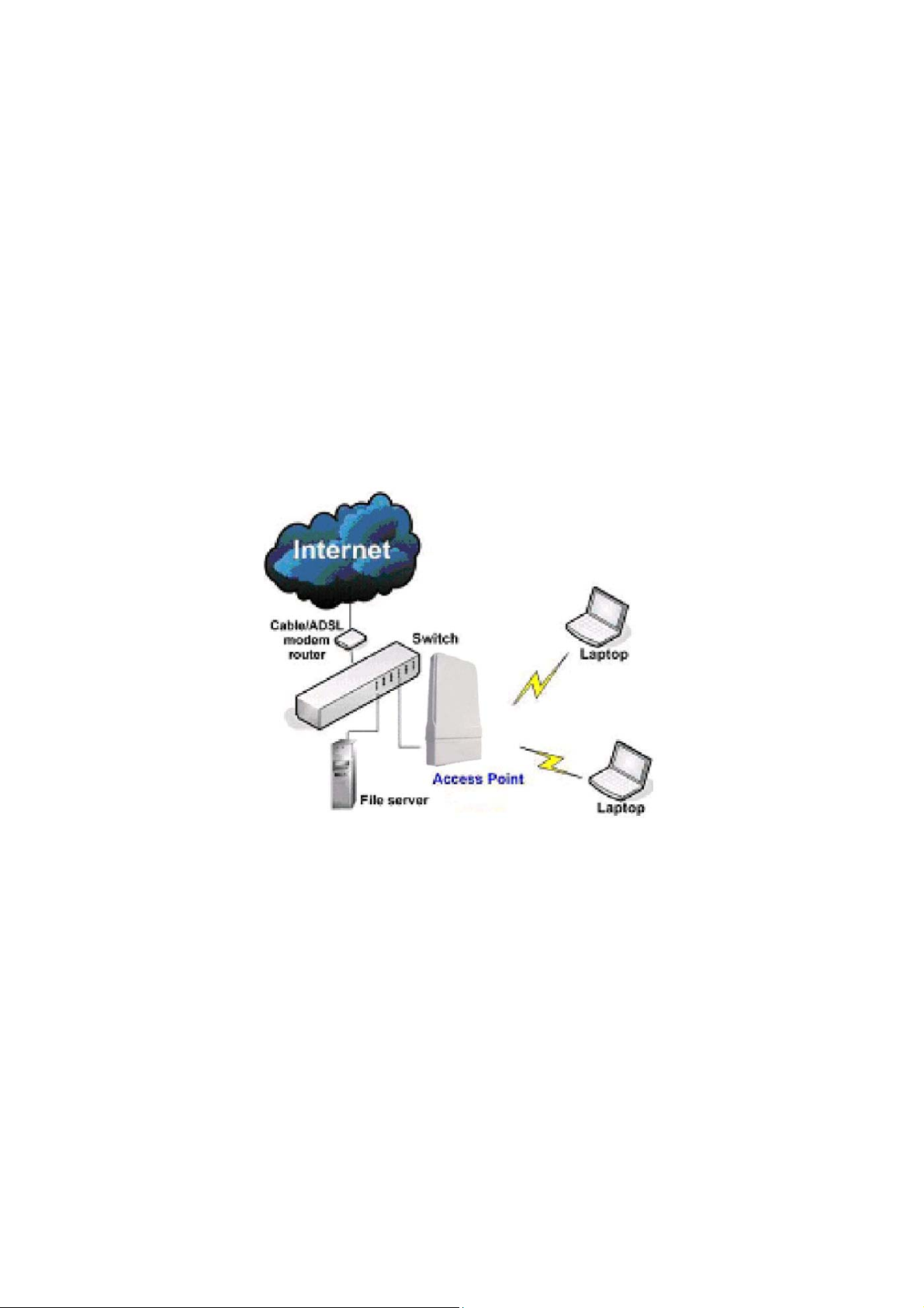
Access Point Mode
The Access Point Mode is the default mode of the access point and
enables the bridging of wireless clients to access the wired network
infrastructure and also enables their communication with each other.
In this example the wireless users are able to access the file server
connected to the switch, through the access point in Access Point
Mode.
Page 9
Page 10
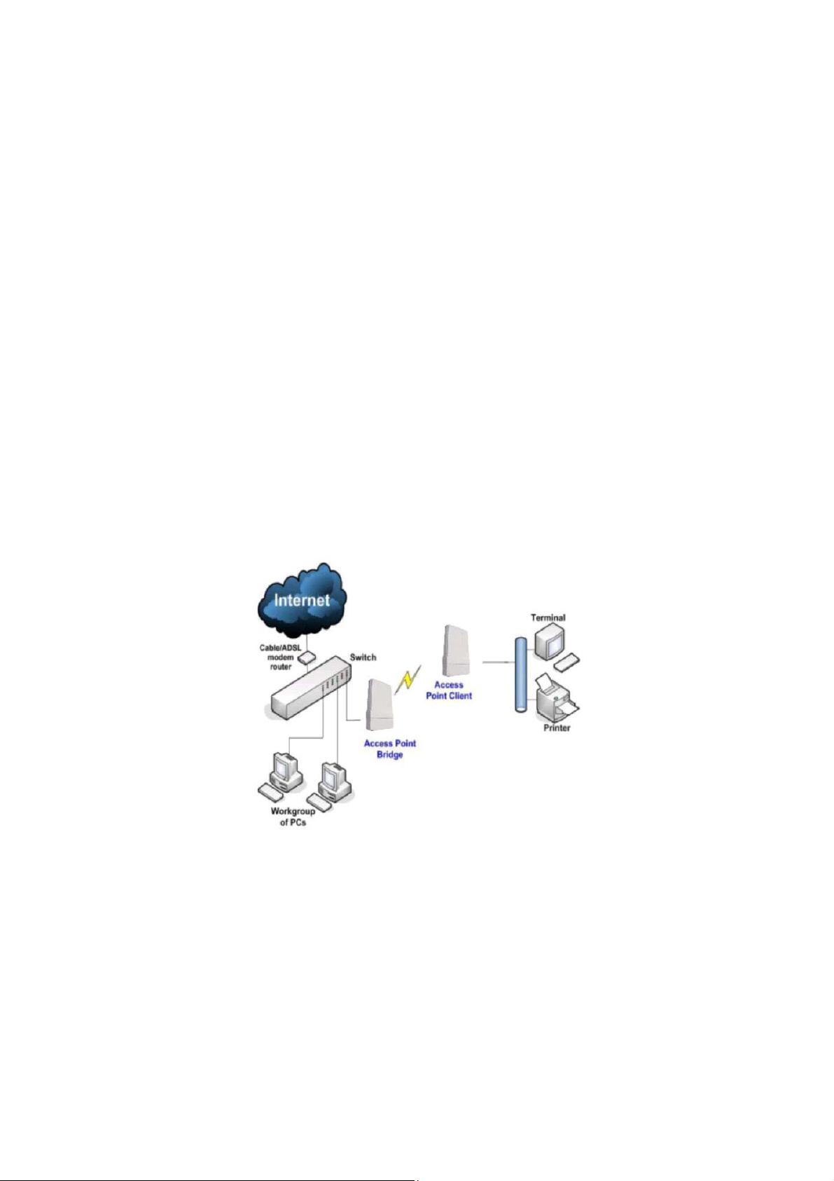
Access Point Client Mode
In Access Point Client Mode the device acts as a wireless client.
When connected to an access point, it creates a network link between
the Ethernet network connected at this client device, and the wireless
Ethernet network connected at the access point.
In this mode it can only connect with another access point. Other
wireless clients cannot connect to it directly unless they are also
connected to the same access point – allowing them to communicate
with all devices connected to the Ethernet port of the access point.
In this example the workgroup PCs can access the printer connected
to the access point in Access Point Client Mode.
Optional additional feature:
Point-to-Point connection in this operation mode is also supported if
you specifically wish to connect with an access point only.
Please refer to the Point-to-Point setup section.
Page 10
Page 11

Wireless Routing Client Mode
In Wireless Routing Client Mode the Ethernet port of the access point
may be used to connect with other devices on the network while
Internet access would be provided through wireless communication
with a wireless ISP.
Page 11
Page 12

Gateway Mode
In Gateway Mode, the access point supports several types of
broadband connections in a wireless network after you have identified
the type of broadband Internet access you are subscribed to.
Page 12
Page 13

Broadband Internet Access Type:
Static IP Address
Use Static IP Address if you have subscribed to a fixed IP address or to a
range of fixed IP addresses from your ISP.
Dynamic IP Address
With Dynamic IP Address the access point requests for, and is
automatically assigned an IP address by your ISP, for instance:
• Singapore Cable Vision
• @HOME Cable Services
PPP over Ethernet (PPPoE)
Use PPPoE if you are using ADSL services in a country utilizing standard
PPPoE authentication, for instance:
• Germany with T-1 Connection
• Singapore with SingNet Broadband or Pacific Internet
Broadband
PPTP
Use PPTP if you are using ADSL services in a country utilizing PPTP
connection and authentication.
Layer Two Tunneling Protocol (L2TP)
L2TP enables ISPs to operate Virtual Private Networks (VPNs)
Page 13
Page 14

Wireless Adapter Mode
In Wireless Adapter Mode, the access point can communicate
wirelessly with another access point to perform transparent bridging
between 2 networks, like in the Access Point Client Mode. In this mode,
however, the wireless adapter connects to a single workstation only.
No client software or drivers are required to use this mode.
Optional additional feature:
Point-to-Point connection in this operation mode is also supported if
you specifically wish to connect with an access point only.
Please refer to the Point-to-Point setup section.
Page 14
Page 15

Transparent Client Mode
In Transparent Client Mode, the access point provides connection with
an access point* acting as the RootAP. This operation is designed for
the implementation of Point-to-Point and Point-to-Multipoint
connections.
Point-to-Point
An access point acts as Root AP and
1 other access point acts as
Transparent Client.
This mode is generally used for outdoor connections over long
distances, or for indoor connections between local networks.
An access point acts as Root AP
and several other access point
Point-to-MultiPoint
acts as Transparent Clients.
Page 15
Page 16

Difference Between other client modes and Transparent Client Mode
Other client modes
Connectivity with any standard
APs.
All devices connected to the
Ethernet ports use a common
MAC address for communications
with the AP.
The Transparent Client Mode is more transparent, making it more
suitable for linking 2 networks together in a point-to-point, or point-tomultipoint network connection.
Connectivity with RootAP-supported
Devices connected to the Ethernet
Transparent Client Mode
APs.
ports flow through freely and
transparently without the MAC
address restriction.
Page 16
Page 17

Panel Views and Description
Features Status and Indication
1 POWER LED
2 10 ACT LED
3 100 ACT
LED
Steady
Red
Off No power is supplied to the device.
Steady
Red
Blinking The respective port is transmitting or
Off No connection is established.
Steady
Red
Blinking
Red
Off No connection is established.
Power is supplied to the device.
The respective port has successfully
connected to the access point.
receiving data.
The respective port has successfully
connected to the access point.
The respective port is transmitting or
receiving data.
Page 17
Page 18

4 WLAN LED
5 WAN Conn
LED
6 DIAG LED Flashing
7 LAN Connection for computer with NIC (Network Interface
8 SURGE
ARRESTOR
10 RESET
BUTTON
Steady
Red
Flashing
Red
Flashing
Red
Red
Card) or Ethernet network card.
Device is power up with PoE on this LAN port.
Connect to a ground wire.
To reboot, press once.
To reset password, press and hold the button for 5
seconds before releasing it.
To restore the factory default settings, press and hold the
button for 8 seconds before releasing it.
Wireless interface up and running.
Ready for operation.
Activity is detected in the wireless network.
Data transmission at WAN connection.
It indicates that the firmware is corrupted.
Page 18
Page 19

Install the Hardware
This section will show you how to install the hardware of the access
point.
• Antenna Alignment
The antenna alignment of the access point must first be
considered to ensure that the signal is strong.
• Installation Direction
After considering the antenna alignment, the direction in which
the access point is facing must be considered to ensure that the
signal is actually being directed to the receiving end.
• Setting Up
Lastly, after making these considerations and confirming the final
position and facing direction of the access point, follow the
instructions to physically set up and complete the installation of
the access point.
Page 19
Page 20

Antenna Alignment
The physical environment of the antenna must be examined when
aligning the antenna. Obstructions, available mounting locations,
and other factors must be considered. Many objects such as forests,
buildings, and hills, can obstruct the antenna, reducing the signal
strength. The antenna can be installed at a height above such
obstructions, and aligned so that antennas are directed at each
other by taking into account the horizontal angle and the vertical
angle of the antenna signal.
When the antenna is at the optimum alignment, there is less
possibility of encountering interference and of causing interference
to anyone else, and strong signal strength can be maintained.
NOTE
When the antennas are at the same height, it is quite simple to align
the antennas. However, when the antennas are at different heights,
greater care has to be taken to ensure that the antennas are properly
aligned.
Page 20
Page 21

Installation Direction
The directional antenna radiates the signal towards the front of the
unit. The unit should be installed in a position whereby the front of
the unit faces the direction you wish to send the signal to. Therefore
the direction you wish to send the signal to has to be considered
before going on to the next step of starting to set up the access
point.
Page 21
Page 22

Setup Requirements
• CAT5/5e Networking Cable.
• At least 1 computer installed with a web browser and a wired or
wireless network interface adapter.
• All network nodes installed with TCP/IP and properly configured
IP address parameters.
Setting Up
You can install your access point on a pole. The mounting method will
be described as shown below.
Note the following guidelines for choosing the best location for your
wireless AP:
• Place the AP as close as possible to the area where users will
require access to the WLAN.
• Choose an elevated location where trees, buildings and large
steel structures will not obstruct the antenna signals and which
offers maximum line-of-sight propagation with the users.
• Select an appropriate antenna to improve range and/or
coverage and the access point also lets you fine-tune
parameters such as the transmit power to achieve the best
results.
Page 22
Page 23

Mount the Unit on a Pole
Unpack the 2 cable ties from the box.
Loop each cable tie through the mounting bracket hole
at the top and bottom. Wrap them round the pole and
tighten the cable ties to secure the unit to the pole.
Connect one end of an RJ45 Ethernet cable to the LAN
OUT port of the Injector and the other end to LAN of the
access point.
Maximum length of the RJ45 Category 5 cable is 100
meters*.
* Up to 200mW radio. For higher power radio need upgrade to higher
rating power adapter.
Page 23
Page 24

Connect the RJ45 Ethernet cable attached to the PoE Injector to a network device,
such as to a switch or to the PC you will use to configure the access point.
PoE power input: Passive PoE (range 12V – 24V DC)
Connect the power adapter in the PoE kit to the main electrical supply and the power
plug into the socket of the injector.
Now, turn on your power supply. Notice that the POWER LED has lighted up. This indicates
that the access point is receiving power through the PoE Injector and that connection
between the access point and your network has been established.
Note:
Please use the power adapter in the PoE kit. Using a power adapter with a different
voltage rating will damage this product.
Page 24
Page 25

Configure the IP Address
After setting up the hardware you need to assign an IP address to your
PC so that it is in the same subnet as the access point.
For Windows 95/98/98SE/ME/NT
SStteepp 11::
From your desktop, right-click the Network Neighborhood icon and se lect Properties.
SStteepp 22:
Select the network adapter that you are using, then right-click and select Properties.
SStteepp 33:
Highlight TCP/IP and click on the
Properties button.
SStteepp 44:
:
:
:
Select the Specify an IP address radio
button.
Set the IP address to 192.168.168.X and
subnet mask to 255.255.255.0, where X
can be any number from 2 to 254.
Page 25
Page 26

:
SStteepp 55:
To verify that the IP address has been
correctly assigned to your PC, go to the
Start menu, select Run, and enter the
command: winipcfg.
Select the Ethernet adapter from the
drop-down list and click OK.
Your PC is now ready to communicate with the access point.
Page 26
Page 27

For Windows XP/2000
SStteepp 11::
Go to your desktop, right-click on the My Network Places icon and select Properties.
SStteepp 22:
:
Right-click the network adapter icon and
select Properties.
SStteepp 33:
:
Highlight Internet Protocol (TCP/IP) and click
on the Properties button.
:
SStteepp 44:
Select the Use the following IP address radio
button.
Set the IP address to 192.168.168.X and
subnet mask to 255.255.255.0, where X can
be any number from 2 to 254.
:
SStteepp 55:
Click on the OK button to close all windows.
Page 27
Page 28

:
SStteepp 66:
To verify that the IP address has been correctly assigned to your PC, go to the Start
menu, Accessories, select Command Prompt, and type the command: ipconfig/all
Your PC is now ready to communicate with your access point.
Page 28
Page 29

Access the Web Interface
Access with uConfig
The UConfig utility provides direct access to the web interface.
SStteepp 11::
From the UUttiilliittiieess section, select to install the uuCCoonnffiigg utility to your hard disk.
SStteepp 22::
After installation double-click on the uuCCoonnffiigg icon and click on the YYeess
button.
Page 29
Page 30

:
SStteepp 33:
Select the access point from the products list and click on the OOppeenn WWeebb
button. To retrieve and display the latest device(s) in the list, click on the
RReeffrreessh
h button.
:
SStteepp 44:
Do not exit the uConfig program while accessing the web-based interface
as this will disconnect you from the device. Click on the OOKK button.
Page 30
Page 31

:
SStteepp 55:
At the login page, press the LLOOGG OONN !! button to enter the configuration
page. The default password is: password
SStteepp 66:
You will then reach the home page of the access point web-based
interface.
:
Page 31
Page 32

Manual access with Internet Explorer
SStteepp 11::
Launch your Web browser and under the TToooollss tab, select IInntteerrnneett OOppttiioonnss.
SStteepp 22::
Open the CCoonnnneeccttiioonnss tab and in the LLAANN SSeettttiinnggss section disable all the option
boxes. Click on the OOKK button to update the changes.
Page 32
Page 33

SStteepp 33::
At the AAddddrreessss bar type in http://192.168.168.1 and press EEnntteerr on your keyboard.
SStteepp 44::
At the login page, click on the LLOOGG OONN !! Button.
You will then reach the home page of the access point web interface.
Page 33
 Loading...