

Page 1

Page 2

2
Table of Contents
Introduction - 4
1.1 Features - 4
1.2 Specifications - 4
1.3 Product Kit - 6
1.4 System Requirements - 6
The 802.11g EzBridge - 7
2.1 Ports - 7
2.2 LEDs - 7
2.3 Installation - 9
Configuring Windows for IP Networking - 10
3.1 If you are using Windows 98/Me - 10
3.2 If you are using Windows 2000 - 11
3.3 If you are using Windows XP - 13
Utilizing the Web Configuration Interface - 16
Station Bridge Mode - 16
4.1 Web Configuration Interface - 17
4.2 The Info Page - 18
4.3 The Configuration Page - 19
4.4 The Encryption Page - 22
4.5 The Advanced Page - 27
4.6 The Admin Page - 30
Page 3

3
Access Point Mode - 33
5.1 Web Configuration Interface - 34
5.2 The Info Page - 34
5.3 The Assoc Page - 35
5.4 The Admin Page - 36
5.5 The Wireless Page - 37
5.6 The Access Page - 39
5.7 The Advanced Page - 40
5.8 The Security Page - 43
5.9 The IP Addr Tab - 46
5.10 The WDS Tab - 48
Appendix A - Warranty Policy - 49
Appendix B - RMA Policy - 50
Appendix C - Regulatory Information - 51
Appendix D - Contact Information - 54
Appendix E - Troubleshooting - 55
Appendix F - Glossary - 56
Page 4

4
Introduction
The 802.11g WLAN Access Point card aims to assist you in easily building
a communicable connection between your wired LAN and one or more
Wireless Local Area Networks. It’s easy to install and operate. To let you
enjoy the most advantages of this product, please read this manual
carefully.
1.1 Features
• 802.11b and 802.11g standards compliant
• Quick and easy to install
• Works with any device that has an Ethernet port
• LED indicators show unit operating status
• FCC Certified for use with YDI amplifiers and outdoor antennas with
the Diamond WLAN Card
• Web-based configuration screen of Access Point enables fast and easy
setup
• Supports RTS threshold control for better throughput
• Wireless data encryption with 64 and 128 bits encryption for security
• One-year warranty
1.2 Specifications
Network Standard: 802.11b or 802.11g
Operating Channels: 11 channels (US, Canada)
Data Rate: Up to 54Mbps
LEDs: LAN, WLAN, Power
Transmit Power: 17 +/- 1dBm (802.11b CCK); 14 +/- 1dBm (802.11g
OFDM)
Page 5

5
Receiver Sensitivity: 11 Mbps: -86dBm (802.11b); 54 Mpbs: -69dBm
(802.11g)
Modulation: CCK, DQPSK, DBPSK (802.11b), BPSK, QPSK, 16QAM,
64QAM (802.11g)
Spreading: DSSS (802.11b), OFDM (802.11g)
Network Protocols: TCP/IP, NetBEUI
Mini PCI Card Antenna Connector: U.FL Connector
(Use connector near the center for external Antenna installation)
Ethernet Port: 100 BaseT Ethernet
Security Filter: MAC Address Filtering for 8 clients
Regulatory Approval: FCC 47CFR15 subpart C (15.247) and Class B
device ETSI 300-3328/301-489-17 (General EMC requirement for RF
equipment)
Weight PCB: 6.87 oz (195g)
Dimensions PCB: 6.3" x 1.2" x 4.7" (161mm x 30mm x 119mm)
Weight w/ NEMA4 Box: 2.5 lb (1.13 Kg)
Dimensions w/ NEMA4 Box: 7" L x 5.4" W x 2.8" H (18cm L x 13.8cm W x
7.3cm H)
Environmental:
Operating Temperature: -4°F to 158°F (-20°C to 70°C)
Humidity: 10 to 90% (non-condensing)
AC Adapter:
Input 120 VAC -- 60 Hz -- 10 W
Output 9 VDC -- 1.5 A
Page 6

6
1.3 Product Kit
The EzBridge Kit contains the following items:
¸ EZBridge 802.11g Unit
¸ Power over Ethernet Injector
¸ AC/DC Power Adapter
¸ Ethernet Cable
¸ Ethernet Crossover Cable
¸ Waterproof RJ-45 Connector
¸ Mounting Hardware
¸ User Manual
Note: If any item listed above is damaged or missing, please contact your
dealer immediately.
1.4 System Requirements
To accomplish a successful operation of your 802.11g WLAN Access Point,
we suggest the following items are required:
¸ One or more PCs (desktop or notebook) with Ethernet interface.
¸ TCP/IP protocol must be installed on all PCs.
¸ Network cables. Use standard 10/100BaseT network (UTP) cables
with RJ45 connectors.
¸ To use the Wireless Access Point, all wireless devices must be
compliant with the IEEE 802.11g specifications.
¸ Microsoft Internet Explorer 5.0 or later or Netscape Navigator 4.7 or
later.
Page 7
7
The 802.11g EzBridge
This section is consisted of three parts. You will learn the guise of the
hardware, including the ports and LEDs, and the installation of Access
Point.
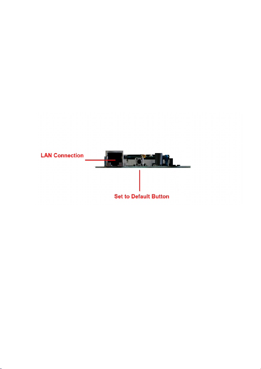
2.1 Ports
The ports are on the rear panel of the device. Please see the following
picture – the rear view of the Access Point to learn more details about your
device.
LAN Connection Use Ethernet straight LAN cable to connect your
PC, hub/switch or broadband router/modem to this
port.
Set to Default Button When you press this button, the Access Point will
reboot and reset current settings to factory default
settings.
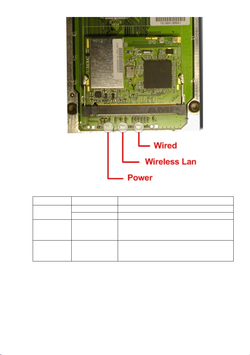
2.2 LEDs
The 802.11g WLAN Access Point includes three types of LED indicators.
Please check the following picture – the front view of the Access Point and
table to obtain the information on the LED indicators on your Access Point.
Page 8
8
LED
Status
Function
On
Power on.
Power
Off
No power.
Wireless LAN
Blinking
On
Off
Blinking: Wireless LAN is transmitting.
On: Wireless LAN connection is active.
Off: Wireless LAN connection is not active.
Wired
Blinking
On
Off
Blinking: Wired LAN is transmitting.
On: Wired LAN is active.
Off: Wired LAN is not active.
Page 9

9
2.3 Installation
Preparation for Installation
Before you actually install your 802.11g WLAN Access Point, please ensure
that all the items listed in “1.4 System Requirements” are prepared, and
then choose the place with the consideration of power outlet and network
connection to install the Access Point.
To avoid causing any damage to the Access Point hardware device, please
do not power up the device before you start to connect it to the port on your
PC.
Also notice that a full installation of your Access Point includes not only the
hardware installation but also the network configuration on your PC. Check
the following section -“Hardware Installation” and the next chapter “Configuring Windows for IP Networking” to obtain complete details.
Hardware Installation
Follow the procedures below to fully install your Access Point hardware
device:
1. Select a suitable place on the network to install the Access Point.
Ensure the Access Point and the DSL/cable modem are powered off.
For best wireless reception and performance, the Access Point should
be positioned in a central location with minimum obstructions between
the Access Point and the PCs.
2. Connect one end of Ethernet cable to Access Point and the other to
switch or hub, and then the Access Point will be connected to the
10/100 Network.
3. Connect the power adapter to the power socket on your Access Point.
4. Last but not the least, check the LEDs on the Access Point to confirm
if the status is okay.
5. Now the hardware installation is complete, and you may proceed to
the next chapter –“Configuring Windows for IP Networking” for
instruction on setting up network configurations.
Page 10
10
Configuring Windows for IP Networking
To establish a communication between your PCs and the 802.11g WLAN
Access Point, you will need an IP address for your computer first. This
section helps you configure the network settings for your operating system.
Please follow the procedures below to complete the settings:
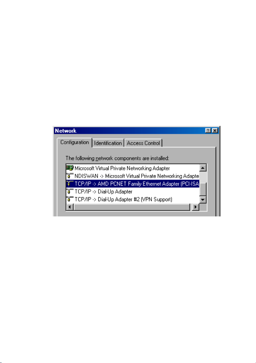
3.1 If you are using Windows 98/Me:
1. Click Start on the taskbar and choose Control Panel from the
submenu of Settings.
2. Select Network to open the Network dialog box, and then under the
Configuration tab, select the TCP/IP protocol for your network card.
3. Click Properties to open the TCP/IP Properties dialog box.
4. Click the IP Address tab and choose Specify an IP address. For
example, type 192.168.1.200 in the IP Address area and
255.255.255.0 in the Subnet Mask area. To ensure the system is
now using the IP address you specify, restart your computer to check
later.
Page 11

11
Note: The IP address must be 192.168.1.x. The value of X should be
ranged from 1 to 254 and is never used by other PCs.
5. Click OK, and then restart the system.
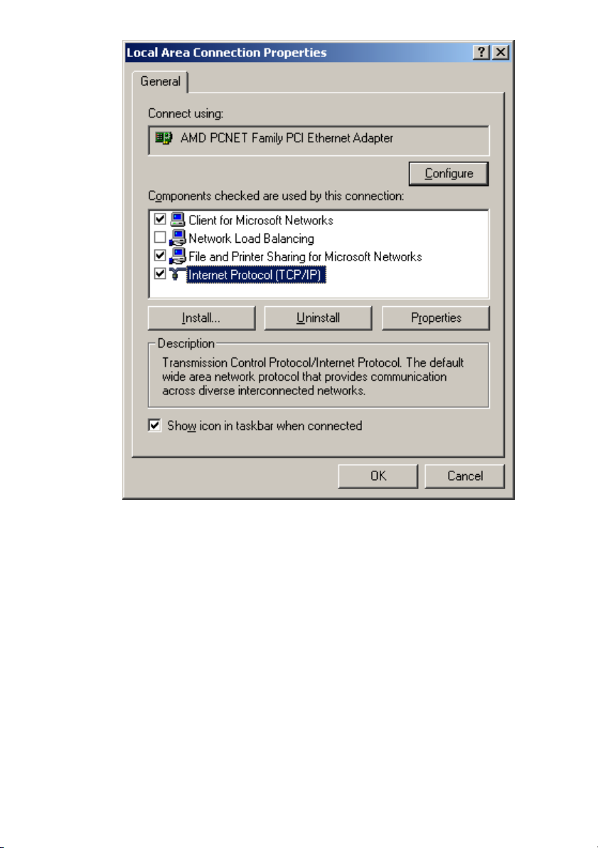
3.2 If you are using Windows 2000:
1. Click Start on the taskbar and choose Network and Dial-up
Connection from the submenu of Settings.
2. Double-click the Local Area Connection open the Local Area
Connection Properties box.
Page 12
12
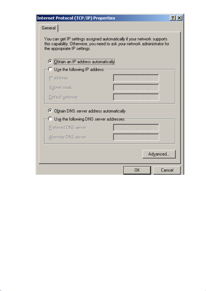
3. Select the Internet Protocol (TCP/IP) for your network card, and then
click Properties to open the Internet Protocol (TCP/IP) Properties
dialog box.
4. Under the General tab, choose Use the following IP address, and
then, for example, enter 192.168.1.200 in the IP Address area and
255.255.255.0 in the Subnet Mask area.
Page 13
13
Note: The IP address must be 192.168.1.x. The value of X should be
ranged from 1 to 254 and is never used by other PCs.
5. Click OK, and then restart the system.
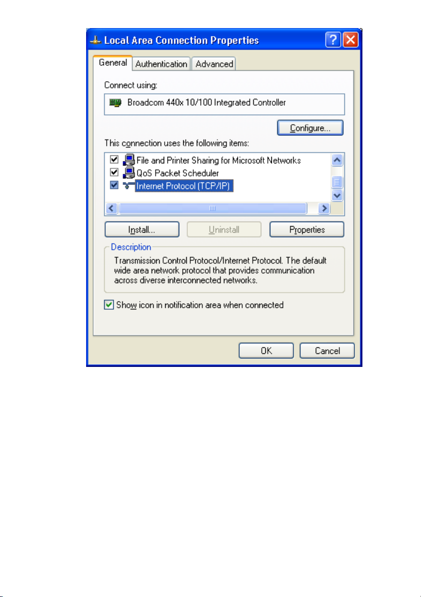
3.3 If you are using Windows XP:
1. Click Start on the taskbar and choose Network from the submenu of
Control Panel.
2. Right-click the Local Area Connection icon and then choose
Properties from the menu. You should see the Local Area
Connection Properties dialog box shown below.
Page 14
14
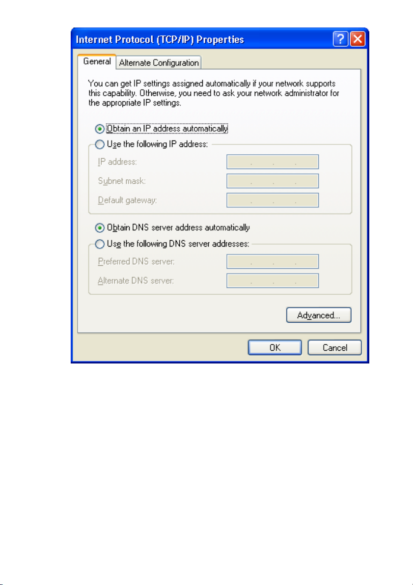
3. Select the Internet Protocol (TCP/IP) for your network card, and then
click Properties.
4. In the opened dialog box, choose Use the following IP address
under the General tab, enter, for example, 192.168.1.200 in the IP
Address area and 255.255.255.0 in the Subnet Mask area.
Page 15
15
Note: The IP address must be 192.168.1.x. The value of X should be
ranged from 1 to 254 and is never used by other PCs.
5. Click OK, and then restart the system.
Page 16
16
Utilizing the Web Configuration Interface
Station Bridge Mode
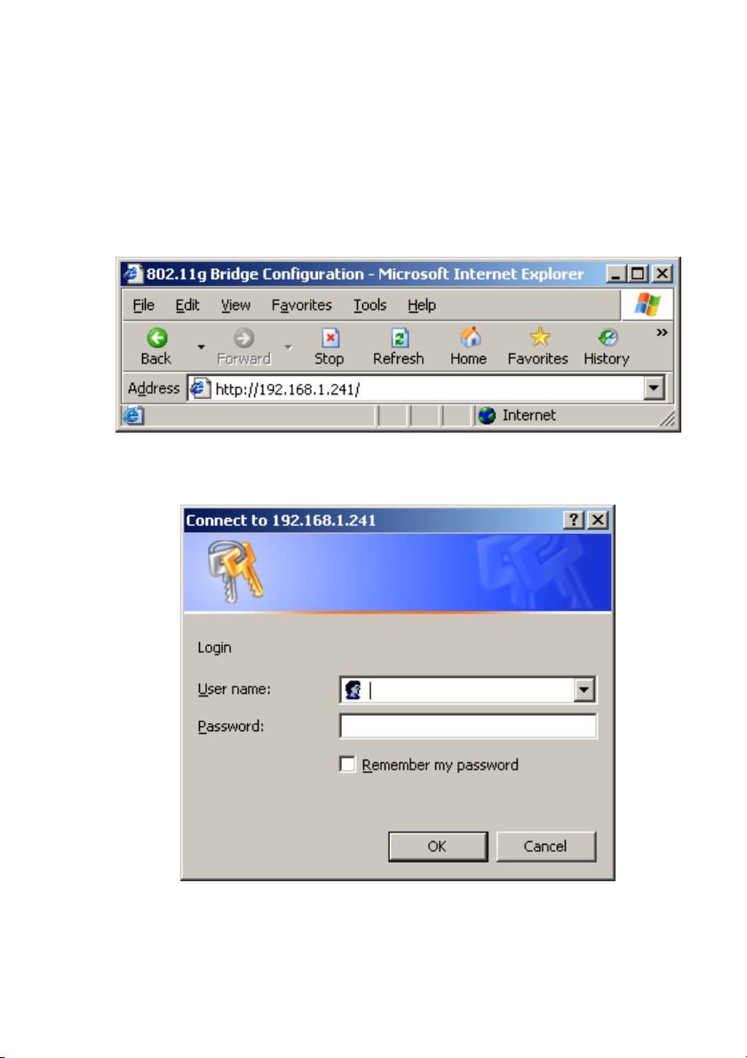
The Access Point’s Web-based Configuration utility presents a user-friendly
interface, so that you can easily execute the program by following the onscreen explanations. Type HTTP://192.168.1.241 in the Address box after
opening your Web browser.
Then press Enter on your keyboard, you will see the Enter Network
Password dialog box appear like the picture below shows.
The default User Name and Password is nil. Leave User Name and
Password field blank and then click OK.
Page 17

17
Note: You may set a new password by clicking the Admin tab after you
enter the Web Configuration page
.
4.1 Web Configuration Interface
Under the main web interface page you will see the following configuration
menu pages:
Info, Configuration, Encryption, Advanced, Admin, and Help. Check the
sections below for detail information on the contents of each menu
interface.
Page 18
18
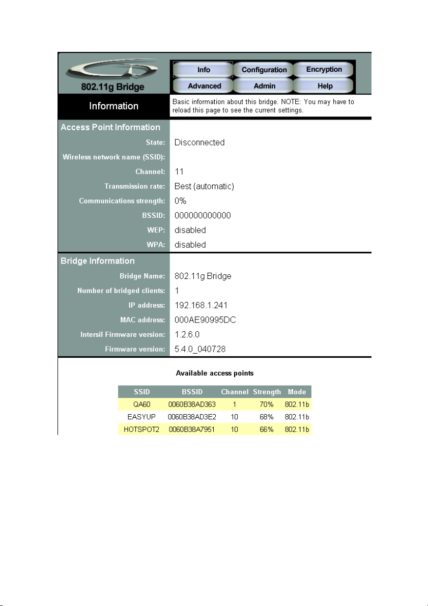
4.2 Info Page
Access Point Information
This section provides the basic access point information in which this unit is
associated with in bridge mode.
Bridge Information
Page 19
19
This section provides the basic bridge setting information.
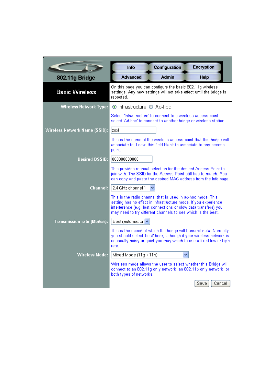
4.3 Configuration Page
Page 20

20
Wireless Network Type
Infrastructure: An 802.11 networking framework in which devices
communicate with each other by first going through an Access Point (AP).
Ad-hoc: An 802.11 networking framework in which devices or stations
communicate directly with each other, without the use of an access point
(AP). Use this mode if there is no wireless infrastructure or where services
are not required.
Wireless Network Name (SSID)
Network Name is also known as SSID, which stands for Service Set
Identifier. Any client in Infrastructure mode has to indicate the SSID of the
intended Access Point to start accessing the service from behind such as
internet access. Type in the name of the Wireless Access Point to connect
this Bridge to an AP.
Channel
Channels are important to understand because they affect the overall
capacity of your Wireless LAN. A channel represents a narrow band of
radio frequency. A radio frequency modulates within a band of frequencies;
as a result, there is a limited amount of bandwidth within any given range to
carry data. It is important that the frequencies do not overlap or else the
throughput would be significantly lowered as the network sorts and
reassembles the data packets sent over the air.
These are the only 3 channels out of the 11 available that do not overlap
with one another. To avoid interference within the network with multiple
APs, set each AP to use one of the 3 channels (e.g. Channel 1) and then
the other AP to be one of the other 2 channels (i.e. Channel 6 or Channel
11) within the range of the wireless radio. This simple method will reduce
interference and improve network reliability.
802.11b/g Wireless Channel Frequency Range: 2.4 GHz – 2.497 GHz
Non-overlapping Channel Frequency Ranges
Channel 1 = 2.401 GHz – 2.423 GHz
Channel 6 = 2.426 GHz – 2.448 GHz
Channel 11 = 2.451 GHz – 2.473 GHz
Americas: Wireless Channels 1-11
Asia: Wireless Channels 1 – 14
Page 21

21
Europe: Wireless Channels 1-13
Transmission rate (Mbits/s)
This option indicates the transmission rate of the bridge. Specify the rate
according to the speed of your wireless network from the list. Most of the
time the default setting Best (automatic) should be selected for best
performance. You may want to adjust the setting manually If your link
quality and signal strength is usually low or high to get the best
performance.
Wireless Mode
Wireless mode allows the user to select whether this Bridge will connect to
an 802.11g only network, an 802.11b only network, or both types of
networks. If you only have b or g wireless devices on the network selecting
802.11b or 802.11g only network will provide better performance then in
mixed mode.
Page 22

22
4.4 Encryption Page
Page 23

23
WPA Configuration
Short for Wi-Fi Protected Access, a Wi-Fi standard that was designed to
improve upon the security features of WEP. WPA has the following
improvements over the WEP.
• Improved data encryption through the temporal key integrity protocol
(TKIP). TKIP scrambles the keys using a hashing algorithm and, by
adding an integrity-checking feature, ensures that the keys haven’t
been tampered with.
• User authentication, which is generally missing in WEP, through the
extensible authentication protocol (EAP). WEP regulates access to a
wireless network based on a computer’s hardware-specific MAC
address, which is relatively simple to be sniffed out and stolen. EAP is
built on a more secure public-key encryption system to ensure that only
authorized network users can access the network.
WPA enabled
To enable the WPA Authenticator
PSK
PSK stands for Pre-Shared-Key and serves as a password. User may key
in a 8 to 63 characters string to set the password or leave it blank, in which
the 802.1x Authentication will be activated. Note that if user key in own
password, make sure to use the same password on client's end.
Page 24

24
WPA Multicast Cipher Type
Select TKIP - WPA Default
WPA Pairwise Cipher Type
Select TKIP - WPA Default
WEP Configuration
Short for Wired Equivalent Privacy, a security protocol for wireless local
area networks (WLANs) defined in the 802.11b standard. WEP is designed
to provide the same level of security as that of a wired LAN.
Enable WEP
To enable the WEP Authenticator
WEP key length
Encryption strength of the web key. Defualt = 64bit (10 Hex digits)
Default WEP key to use
Select the key to be used as the default key. Data transmissions are always
encrypted using the default key. The other keys can only be used to decrypt
received data.
WEP key
Type in a 10 hex digit password if using 64 bit WEP key length.
Type in 26 hex digits password if using 128 bit WEP key length.
Hex Digits = 0-9 and A-F
Deny unencrypted data
Force the peer connection(s) to this bridge to use encryption to farther
increase security.
Authentication
Page 25

25
• Open - Open system authentication involves a two-step authentication
transaction sequence. The first step in the sequence is the identity
assertion and request for authentication. The second step in the
sequence is the authentication result. If it is “successful”, The station
shall be mutually authenticated.
Open system authentication does not provide authentication. It provides
identification using the wireless adapter's MAC address. Open system
authentication is used when no authentication is required. It is the default
authentication algorithm.
Open system authentication uses the following process:
1. The authentication-initiating wireless client sends an IEEE 802.11
authentication management frame that contains its identity.
2. The receiving wireless AP checks the initiating station's identity and
sends back an authentication verification frame.
With some wireless APs, you can configure the MAC addresses of allowed
wireless clients. However, configuring the MAC address does not provide
sufficient security because the MAC address of a wireless client can be
spoofed.
• Shared Key - Shared key authentication supports authentication of
stations as either a member of those who know a shared secret key or
a member of those who do not.
Shared key authentication is not secure and is not recommended for use. It
verifies that an authentication-initiating station has knowledge of a shared
secret. This is similar to preshared key authentication for Internet Protocol
security (IPSec). The 802.11 standard currently assumes that the shared
secret is delivered to the participating wireless clients by means of a more
secure channel that is independent of IEEE 802.11. In practice, a user
manually types this secret for the wireless AP and the wireless client.
Shared key authentication uses the following process:
1. The authentication-initiating wireless client sends a frame consisting of
an identity assertion and a request for authentication.
2. The authenticating wireless node responds to the authenticationinitiating wireless node with challenge text.
Page 26

26
3. The authentication-initiating wireless node replies to the authenticating
wireless node with the challenge text that is encrypted using WEP and
an encryption key that is derived from the shared key authentication
secret.
4. The authentication result is positive if the authenticating wireless node
determines that the decrypted challenge text matches the challenge
text originally sent in the second frame. The authenticating wireless
node sends the authentication result.
Because the shared key authentication secret must be manually distributed
and typed, this method of authentication does not scale appropriately in
large infrastructure network mode, such as corporate campuses.
Page 27

27
4.5 Advanced Page
Page 28

28
Cloning
Cloning Mode
• Ethernet Client
If set to "Ethernet Client", the MAC Address from the first Ethernet client
that transmits data through the Bridge will be used. Which means the client
MAC address will become the alias address to the Bridge.
• WLAN Card
If set to "WLAN Card", the MAC Address of the WLAN Card will be used.
When multiple Ethernet devices are connected to the Bridge, the MAC
Address of the Bridge will not change.
Advanced Wireless
Fragmentation threshold
Fragmentation Threshold is the maximum length of the frame, beyond
which payload must be broken up (fragmented) into two or more frames.
Collisions occur more often for long frames because sending them
occupies the channel for a longer period of time, increasing the chance that
another station will transmit and cause collision. Reducing Fragmentation
Threshold results in shorter frames that "busy" the channel for shorter
periods, reducing packet error rate and resulting retransmissions. However,
shorter frames also increase overhead, degrading maximum possible
throughput, so adjusting this parameter means striking a good balance
between error rate and throughput.
RTS threshold
RTS Threshold is the frame size above which an RTS/CTS handshake will
be performed before attempting to transmit. RTS/CTS asks for permission
to transmit to reduce collisions, but adds considerable overhead. Disabling
RTS/CTS can reduce overhead and latency in WLANs where all stations
are close together, but can increase collisions and degrade performance in
WLANs where stations are far apart and unable to sense each other to
avoid collisions (aka Hidden Nodes). If you are experiencing excessive
collisions, you can try turning RTS/CTS on or (if already on) reduce
RTS/CTS Threshold on the affected stations.
Page 29

29
Maximum burst time
Maximum burst time is a feature based on the PRISM Nitro; a new WLAN
software solution that more than triples 802.11g throughput in a mixedmode environment and offers up to 50 percent greater throughput
performance in 802.11g-only networks. PRISM Nitro is fully IEEE 802.11
compliant and uses prioritization algorithms and enhanced protection
mechanisms to significantly increase wireless networking performance.
The recommended value for the maximum burst time for 11b or the mixed
11b/g environment is 650. For the 11g only mode use the value 1400.
Page 30
30
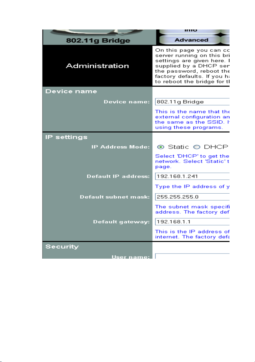
4.6 Admin Page
Page 31

31
Device name
You can name this bridge for identification. You can leave it blank without
entering anything. However, the name for the bridge will be useful for
identification especially when there are more than one bridge in your
wireless network.
IP settings
IP Address Mode
• Static
Manually setup an ip for this device.
• DHCP
Set up the bridge as a DHCP client which will pick up an IP from a DHCP
server.
Default IP address
The default IP address is 192.168.1.240
Page 32

32
Default subnet mask
The factory subnet default value is 255.255.255.0
Default gateway
The factory gateway default address is 192.168.1.1
Security
Set up the administrative login name and password for the bridge.
User name
This is the user name that you must type when logging into the web
interface.
Administrator password
This is the password that you must type when logging into the web
interface. You must enter the same password into both boxes, for
confirmation.
Commands
Reboot bridge
All changes from the web interface will not take effect until the Reboot.
Reset to factory defaults
Reset all changes made to the bridge back to factory defualt
Upgrade firmware
Upload firmware from a selected source path.
Page 33

33
Access Point Mode
The Access Point’s Web-based Configuration utility presents a user-friendly
interface, so that you can easily execute the program by following the onscreen explanations. Type HTTP://192.168.1.240 in the Address box after
opening your Web browser.
Then press Enter on your keyboard, you will see the Enter Network
Password dialog box appear like the picture below shows.
The default User Name and Password is nil. Leave User Name and
Password field blank and then click OK.
Note: You may set a new password by clicking the Admin tab after you
enter the Access Point Configuration Web page.
Page 34

34
5.1 Web Configuration Interface
Under the main web interface page you will see the following configuration
menu pages:
Info, Assoc, Admin, Wireless, Access, Advanced, Secruity, IP Addr,
WDS and Help. Check the sections below for detail information on the
contents of each menu interface.
5.2 Info Page
Access Point Information
Shows the following basic information of the unit:
Page 35

35
• Name and MAC address of the AP.
• Number of wireless stations associated with this unit.
• Firmware version of the wireless component.
• Firmware version of the complete system.
Current IP Settings
Shows the current ip address of the unit and the DHCP client status.
Current Wireless Settings
Shows the unit wireless broadcast mode, the name of the wireless network
setup on the unit, the channel of the wireless network and the type of
encryption that unit is currently using.
5.3 Assoc Tab
A list of MAC addresses of other wireless stations that are associated with
this unit. (Bridges, Routers, Clients?)
Page 36

36
5.4 Admin Page
User Name
This is the user name that you must type when logging into the web
interface.
Administrator Password
This is the password that you must type when logging into the web
interface. You must enter the same password into both boxes, for
Page 37

37
confirmation.
Commands
Reboot access point
All changes from the web interface will not take effect until the Reboot.
Reset to factory defaults
Reset all changes made to the bridge back to factory default
Upgrade firmware
Upload firmware from a selected source path.
Page 38

38
5.5 Wireless Page
Visibility Status
This controls the SSID broadcasting function. If enabled the SSID will be
broadcasted out to all the wireless clients in the area. If disabled the
wireless clients will not be able to pickup the SSID but must explicitly know
the SSID of the unit in order to associate. The recommended practice is to
set the visibility to invisible after setting up the wireless network.
Wireless Mode
The recommended practice is to set up the wireless mode to support one
standard for best performance and stability.
Page 39

39
Wireless Network Name (SSID)
Service Set Identifier (SSID) is the name in which other wireless clients will
see this unit as when searching on the wireless network.
Channel
Channels are important to understand because they affect the overall
capacity of your Wireless LAN. A channel represents a narrow band of
radio frequency. A radio frequency modulates within a band of frequencies;
as a result, there is a limited amount of bandwidth within any given range to
carry data. It is important that the frequencies do not overlap or else the
throughput would be significantly lowered as the network sorts and
reassembles the data packets sent over the air.
These are the only 3 channels out of the 11 available that do not overlap
with one another. To avoid interference within the network with multiple
APs, set each AP to use one of the 3 channels (e.g. Channel 1) and then
the other AP to be one of the other 2 channels (i.e. Channel 6 or Channel
11) within the range of the wireless radio. This simple method will reduce
interference and improve network reliability.
Wireless Channel Frequency Range: 2.4 GHz – 2.497 GHz
Channel 1 = 2401 Hz – 2423 Hz
Channel 6 = 2426 Hz – 2448 Hz
Channel 11 = 2451 Hz – 2473 Hz
Americas: Wireless Channels 1-11
Asia: Wireless Channels 1 – 14
Europe: Wireless Channels 1-13
Transmission rate (Mbits/s)
This option indicates the transmission rate of the bridge. Specify the rate
according to the speed of your wireless network from the list. Most of the
time the default setting Best (automatic) should be selected for best
performance. You may want to adjust the setting manually If your link
quality and signal strength is usually low or high to get the best
performance.
5.7 Access Page
Page 40

40
Enable access control
If enabled, this feature will allow you to associate devices by MAC
addresses up to 8 different units. Anything that are not programmed into the
list will be blocked out from associating with the unit.
Page 41

41
5.7 Advanced Page
Maximum associated stations
This the maximum number of wireless clients that can be associated at any
one time.
Page 42

42
Fragmentation threshold
Fragmentation Threshold is the maximum length of the frame, beyond
which payload must be broken up (fragmented) into two or more frames.
Collisions occur more often for long frames because sending them
occupies the channel for a longer period of time, increasing the chance that
another station will transmit and cause collision. Reducing Fragmentation
Threshold results in shorter frames that "busy" the channel for shorter
periods, reducing packet error rate and resulting retransmissions. However,
shorter frames also increase overhead, degrading maximum possible
throughput, so adjusting this parameter means striking a good balance
between error rate and throughput.
RTS threshold
RTS Threshold is the frame size above which an RTS/CTS handshake will
be performed before attempting to transmit. RTS/CTS asks for permission
to transmit to reduce collisions, but adds considerable overhead. Disabling
RTS/CTS can reduce overhead and latency in WLANs where all stations
are close together, but can increase collisions and degrade performance in
WLANs where stations are far apart and unable to sense each other to
avoid collisions (aka Hidden Nodes). If you are experiencing excessive
collisions, you can try turning RTS/CTS on or (if already on) reduce
RTS/CTS Threshold on the affected stations.
Beacon period
In wireless networking, a beacon is a packet sent by a connected device to
inform other devices of its presence and readiness.
When a wirelessly networked device sends a beacon, it includes with it a
beacon interval, which specifies the period of time before it will send the
beacon again. The interval tells receiving devices on the network how long
they can wait in low-power mode before waking up to handle the beacon.
Network managers can adjust the beacon interval, usually measured in
milliseconds (ms) or its equivalent, kilo microseconds (Kmsec).
DTIM interval
Delivery Traffic Indication Message. A DTIM is a signal sent as part of a
beacon by an access point to a client device in sleep mode, alerting the
device to a packet awaiting delivery. A DTIM interval, also known as a Data
Beacon Rate, is the frequency at which an access point's beacon will
Page 43

43
include a DTIM. This frequency is usually measured in milliseconds (ms) or
its equivalent, kilo microseconds (Kmsec).
Maximum burst time
Maximum burst time is a feature based on the PRISM Nitro; a new WLAN
software solution that more than triples 802.11g throughput in a mixedmode environment and offers up to 50 percent greater throughput
performance in 802.11g-only networks. PRISM Nitro is fully IEEE 802.11
compliant and uses prioritization algorithms and enhanced protection
mechanisms to significantly increase wireless networking performance.
The recommended value for the maximum burst time for 11b or the mixed
11b/g environment is 650. For the 11g only mode use the value 1400.
Enable PSM buffer
PSM stands for Power Save Mechanisms. Turn this on to enable support
for stations in power save mode.
Page 44

44
5.8 Security Page
WPA configuration
Short for Wi-Fi Protected Access, a Wi-Fi standard that was designed to
improve upon the security features of WEP. WPA has the following
improvements over the WEP.
• Improved data encryption through the temporal key integrity
Page 45

45
protocol (TKIP). TKIP scrambles the keys using a hashing
algorithm and, by adding an integrity-checking feature, ensures that
the keys haven’t been tampered with.
• User authentication, which is generally missing in WEP, through the
extensible authentication protocol (EAP). WEP regulates access to
a wireless network based on a computer’s hardware-specific MAC
address, which is relatively simple to be sniffed out and stolen.
EAP is built on a more secure public-key encryption system to
ensure that only authorized network users can access the network.
WPA enabled
To enable the WPA Authenticator
PSK pass-phrase
PSK stands for Pre-Shared-Key and serves as a password. User may key
in a 8 to 63 characters string to set the password or leave it blank, in which
the 802.1x Authentication will be activated. Note that if user key in own
password, make sure to use the same password on client's end.
WPA Multicast Cipher Type
Select TKIP - WPA Default
WPA Pairwise Cipher Type
Select TKIP - WPA Default
WPA Group Key Update Interval
This shows the time period for the next key change. The default value is
3600 (seconds). Users may set the values of their preference.
802.1X configuration
Remote RADIUS server configuration settings
Page 46

46
Authentication timeout (mins)
The default value is 60(minutes). When the time expires, the device will reauthenticate with RADIUS server.
RADIUS server IP address
Enter the RADIUS server IP.
RADIUS server port number
Port used for RADIUS, the number of ports must be the same as the
RADIUS server , normally the port is 1812
RADIUS server shared secret
When registered with a RADIUS server, a pass word will be assigned. This
would be the RADIUS server shared secret.
MAC Address Authentication
Use client MAC address for authentication with RAIDUS server
Page 47

47
5.9 IP Addr Page
IP Address Mode
• Static
Manually setup an ip for this device.
• DHCP
Set up the bridge as a DHCP client which will pick up a free IP from a
Page 48

48
DHCP server.
Default IP address
The default IP address is 192.168.1.240
Default subnet mask
The factory subnet default value is 255.255.255.0
Default gateway
The factory gateway default address is 192.168.1.1
Access point name
Access point name
You can name this access point for identification. You can leave it blank
without entering anything. However, the name for the access point will be
useful for identification especially when there are more than one access
points in your wireless network.
Page 49

49
5.10 WDS Page
Enable WDS
The Repeater (WDS) functionality enables this AP to support wireless traffic
to other WDS relay Access Points. The distance of wireless networking is
thus extended for authenticated client devices that can roam from this
Access Point to another. This Access Point can support up to 6 other
Access Points for WDS communication.
Enter the MAC Address for the new Access Point to participate the WDS
with this Access Point. The MAC Address of this Access Point should be
also added in other Access Points so that they can communicate. You can
add up to 6 WDS Access points.
Page 50

50
Appendix A: Warranty Policy
Limited Warranty
All Teletronics’ products warranted to the original purchaser to be free from
defects in materials and workmanship under normal installation, use, and
service for a period of one (1) year from the date of purchase.
Under this warranty, Teletronics International, Inc. shall repair or replace (at
its option), during the warranty period, any part that proves to be defective
in material of workmanship under normal installation, use and service,
provided the product is returned to Teletronics International, Inc., or to one
of its distributors with transportation charges prepaid. Returned products
must include a copy of the purchase receipt. In the absence of a purchase
receipt, the warranty period shall be one (1) year from the date of
manufacture.
This warranty shall be voided if the product is damaged as a result of
defacement, misuse, abuse, neglect, accident, destruction or alteration of
the serial number, improper electrical voltages or currents, repair, alteration
or maintenance by any person or party other than a Teletronics
International, Inc. employee or authorized service facility, or any use in
violation of instructions furnished by Teletronics International, Inc.
This warranty is also rendered invalid if this product is removed from the
country in which it was purchased, if it is used in a country in which it is not
registered for use, or if it is used in a country for which it was not designed.
Due to variations in communications laws, this product may be illegal for
use in some countries. Teletronics International, Inc. assumes no
responsibility for damages or penalties incurred resulting from the use of
this product in a manner or location other than that for which it is intended.
IN NO EVENT SHALL TELETRONICS INTERNATIONAL, INC. BE LIABLE
FOR ANY SPECIAL, INCIDENTAL OR CONSEQUENTIAL DAMAGES
FOR BREACH OF THIS OR ANY OTHER WARRANTY, EXPRESSED OR
IMPLIED, WHATSOEVER.
Some states do not allow the exclusion or limitation of special, incidental or
consequential damages, so the above exclusion or limitation may not apply
to you.
This warranty gives you specific legal rights, and you may also have other
rights that vary from state to state.
Page 51

51
Appendix B: RMA Policy
Product Return Policy
It is important to us that all Teletronics’ products are bought with full
confidence. If you are not 100% satisfied with any product purchased from
Teletronics you may receive a prompt replacement or refund, subject to the
terms and conditions outlined below.
IMPORTANT: Before returning any item for credit or under warranty repair,
you must obtain a Return Merchandise Authorization (RMA) number by
filling out the RMA form. Products will not be accepted without an RMA
number. All products being shipped to Teletronics for repair / refund /
exchange must be freight prepaid (customer pays for shipping). For all
under warranty repair/replacement, Teletronics standard warranty applies.
30-Day full refund or credit policy:
1. Product was purchased from Teletronics no more than 30 day prior to
the return request.
2. All shipping charges associated with returned items are nonrefundable.
3. Products are returned in their original condition along with any
associated packaging, accessories, mounting hardware and manuals.
Any discrepancy could result in a delay or partial forfeiture of your
credit.
Unfortunately Teletronics cannot issue credits for:
1. Products not purchased from Teletronics directly. If you purchased from
a reseller or distributor you must contact them directly for return
instructions.
2. Damaged items as a result of misuse, neglect, or improper
environmental conditions.
3. Products purchased direct from Teletronics more than 30 days prior to
a product return request.
To return any product under 1 year warranty for repair/replacement, follow
the RMA procedure.
Page 52

52
Appendix C: Regulatory Information
Statement of Conditions
We may make improvements or changes in the product described in this
documentation at any time. The information regarding to the product in this
manual are subject to change without notice.
We assume no responsibility for errors contained herein or for direct,
indirect, special, incidental, or consequential damages with the furnishing,
performance, or use of this manual or equipment supplied with it, even if
the suppliers have been advised of the possibility of such damages.
Electronic Emission Notices
This device complies with Part 15 of the FCC Rules. Operation is subject to
the following two conditions:
(1) This device may not cause harmful interference.
(2) This device must accept any interference received, including
interference that may cause undesired operation.
FCC Information
The Federal Communication Commission Radio Frequency Interference
Statement includes the following paragraph:
The equipment has been tested and found to comply with the limits for a
Class B Digital Device, pursuant to part 15 of the FCC Rules. These limits
are designed to provide reasonable protection against harmful interference
in a residential installation. This equipment generates, uses and can radiate
radio frequency energy and, if not installed and used in accordance with
the instruction, may cause harmful interference to radio communication.
However, there is no guarantee that interference will not occur in a
particular installation. If this equipment does cause harmful interference to
radio or television reception, which can be determined by turning the
equipment off and on, the user is encouraged to try to overcome the
interference by one or more of the following measures:
Page 53

53
- Reorient or relocate the receiving antenna.
- Increase the separation between the equipment and receiver.
- Connect the equipment into an outlet on a circuit different from that
to which the receiver is connected.
- Consult the dealer or an experienced radio/TV technician for help.
- The equipment is for home or office use.
Important Note
FCC RF Radiation Exposure Statement: This equipment complies with
FCC RF radiation exposure limits set forth for an uncontrolled environment.
This equipment should be installed and operated with a minimum distance
of 20cm between the antenna and your body and must not be co-located or
operating in conjunction with any other antenna or transmitter.
Caution: Changes or modifications not expressly approved by the party
responsible for compliance could void the user's authority to operate the
equipment.
R&TTE Compliance Statement
This equipment complies with all the requirements of the Directive
1999/5/EC of the European Parliament and the Council of 9 March 1999 on
radio equipment and telecommunication terminal equipment (R&TTE)and
the mutual recognition of their conformity. The R&TTE Directive repeals
and replaces in the directive 98/13/EEC. As of April 8, 2000.
European Union CE Marking and Compliance
Notices
Products intended for sale within the European Union are marked, which
indicates compliance with the applicable directives identified below. This
equipment also carries the Class 2 identifier.
With the Conformité Européene (CE) and European standards and
amendments, we declare that the equipment described in this document is
in conformance with the essential requirements of the European Council
Directives, standards, and other normative documents listed below:
73/23/EEC Safety of the User (article 3.1.a)
89/336/EEC Electromagnetic Compatibility (article 3.1.b)
Page 54

54
1999/5/EC (R&TTE) Radio and Telecommunications Terminal Equipment
Directive.
EN 60950 2000 Safety of Information Technology Equipment, Including
Electrical Business Equipment.
EN 300 328 V1.4.1(2003) Electromagnetic compatibility and Radio
spectrum Matters (ERM); Wideband Transmission systems;Data
transmission equipment operating in the 2,4 GHz ISM band and using
spread spectrum modulation techniques;Harmonized EN covering essential
requirements under article 3.2 of the R&TTE Directive.
EN 301 489-1, V1.4.1(2002); EN 301 489-17, V1.2.1(2002) –
Electromagnetic compatibility and radio spectrum matters (ERM);
electromagnetic compatibility (EMC) standard for radio equipment and
services: Part 1: Common technical requirements; Part 17: Part 17:
Specific conditions for 2,4 GHz wideband transmission systems and5 GHz
high performance RLAN equipment
Warning: According to ERC/REC 70-30 appendix 3 National Restrictions,
annex 3 Band A “RLANs and HIPERLANs.” See list of 802.11b/g
restrictions for specific countries under the heading “European Economic
Area Restrictions” as below.
English
This product follows the provisions of the European Directive 1999/5/EC.
Danish
Dette produkt er i overensstemmelse med det europæiske direktiv
1999/5/EF
Dutch
Dit product is in navolging van de bepalingen van Europees Directief
1999/5/EC.
Finnish
Tämä tuote noudattaa EU-direktiivin 1999/5/EY määräyksiä.
French
Ce produit est conforme aux exigences de la Directive Européenne
1999/5/CE.
Page 55

55
Appendix D: Contact Information
Need to contact Teletronics?
Visit us online for information on the latest products and updates to your
existing products at: http://www.teletronics.com
Can't find information about a product you want to buy on the web? Do you
want to know more about networking with Teletronics products?
Give us a call at: 301-309-8500 Or fax your request in to: 301-309-8551
Don't wish to call? You can e-mail us at: support@teletronics.com
If any Teletronics product proves defective during its warranty period,
you can email the Teletronics Return Merchandise Authorization
department for obtaining a Return Authorization Number at:
rma@teletronics.com
(Details on Warranty and RMA issues can be found in Appendix A and B)
Page 56

56
Appendix E: TROUBLESHOOTING
Symptom: Power LED off
Resolution:
Connect the power adapter to your G Series Wireless AP and plug it into
the power outlet.
Note: Only use the power adapter provided with your AP. Using any other
adapter might damage your G Series Wireless AP.
Symptom: Can not setting G Series Wireless AP through web browser
Resolution:
The Ethernet cable (RJ45-crossover) must plug to LAN port of G Series
Wireless AP.
Check that the IP address in the URL field is correct.
Check your host PC IP address. If the IP address of G Series Wireless AP
is 192.168.1.240 then your IP of host PC must set 192.168.1.1~239.
Symptom: Forgot IP address
Resolution:
If you forgot the IP address of G Series Wireless AP you can press reset
button to restore the default factory settings by pressing this button for five
seconds. The default IP is 192.168.1.240.
Symptom: Can not setting G Series Wireless AP from a Wireless LAN
card
Resolution:
Make sure that the Mode, SSID, Channel and encryption settings are set
the same on each Wireless LAN card.
Make sure that your computer is within range and free from any strong
electrical devices that may cause interference.
Check your IP Address to make sure that it is compatible with the G Series
Wireless AP.
Page 57

57
Appendix F: Glossary
802.1x - The standard for wireless LAN authentication used between an AP
and a client. 802.1x with EAP will initiate key handling.
Ad-Hoc Network - The wireless network based on a peer-to-peer
communications session. Also referred to as AdHoc.
Access Point - Access points are stations in a wireless LAN that are
connected to an Ethernet hub or server. Users can roam within the range of
access points and their wireless device connections are passed from one
access point to the next.
Authentication - Authentication refers to the verification of a transmitted
message's integrity.
Beacon - In wireless networking, a beacon is a packet sent by a connected
device to inform other devices of its presence and readiness.
Beacon interval - When a wirelessly networked device sends a beacon, it
includes with it a beacon interval, which specifies the period of time before
it will send the beacon again. The interval tells receiving devices on the
network how long they can wait in low-power mode before waking up to
handle the beacon. Network managers can adjust the beacon interval,
usually measured in milliseconds (ms) or its equivalent, kilo microseconds
(Kmsec).
BSS - Basic Service Set. When a WLAN is operating in infrastructure
mode, each access point and its connected devices are called the Basic
Service Set.
BSSID - The unique identifier for an access point in a BSS network. See
SSID for more details.
DHCP - DHCP (Dynamic Host Configuration Protocol) software
automatically assigns IP addresses to client stations logging onto a TCP/IP
network, which eliminates the need to manually assign permanent IP
addresses.
DSSS (Direct Sequence Spread Spectrum) - Method of spreading a
wireless signal into wide frequency bandwidth.
Page 58

58
Dynamic IP Address - An IP address that is automatically assigned to a
client station in a TCP/IP network, typically by a DHCP server.
DNS (Domain Name System): System used to map readable machine
names into IP addresses
DTIM - DTIM (Delivery Traffic Indication Message) provides client stations
with information on the next opportunity to monitor for broadcast or
multicast messages.
DTIM interval - A DTIM interval, also known as a Data Beacon Rate, is the
frequency at which an access point's beacon will include a DTIM. This
frequency is usually measured in milliseconds (ms) or its equivalent, kilo
microseconds (Kmsec).
ESS - Extended Service Set. ESS is the collective term for two or more
BSSs that use the same switch in a LAN.
ESSID - Extended Service Set Identifier. An ESSID is the unique identifier
for an ESS. See SSID for more details.
Filter - Filters are schemes, which only allow specified data to be
transmitted. For example, the router can filter specific IP addresses so that
users cannot connect to those addresses.
Firmware: Programming inserted into programmable read-only memory,
thus becoming a permanent part of a computing device.
Fragmentation - Refers to the breaking up of data packets during
transmission.
Gateway - Gateways are computers that convert protocols enabling
different networks, applications, and operating systems to exchange
information.
IBSS - Independent Basic Service Set. See ad-hoc network
Infrastructure Mode - When a wireless network functions in infrastructure
mode, every user communicates with the network and other users through
an access point; this is the typical way corporate WLANs work. An
alternative is ad-hoc mode, but users would have to switch to infrastructure
mode to access a network's printers and servers.
ISP - An ISP is an organization providing Internet access service via
modems, ISDN (Integrated Services Digital Network), and private lines.
Page 59

59
LAN(Local Area Network): A group of computers and peripheral devices
connected to share resources.
MAC (Medium Access Control) Address: A unique number that
distinguishes network cards.
MTU - MTU (Maximum Transmission/Transfer Unit) is the largest packet
size that can be sent over a network. Messages larger than the MTU are
divided into smaller packets.
NAT - NAT (Network Address Translation - also known as IP
masquerading) enables an organization to present itself to the Internet with
one address. NAT converts the address of each LAN node into one IP
address for the Internet (and vice versa). NAT also provides a certain
amount of security by acting as a firewall by keeping individual IP
addresses hidden from the WAN.
Preamble - Preamble refers to the length of a CRC (Cyclic Redundancy
Check) block that monitors’ communications between roaming wireless
enabled devices and access points.
Protocol - A standard way of exchanging information between computers.
RADIUS (Remote Authentication Dial In User Service): A server that issues
authentication key to clients.
RAM (Random Access Memory): Non-permanent memory.
RIP - RIP (Routing Information Protocol) is a routing protocol that is
integrated in the TCP/IP protocol. RIP finds a route
that is based on the smallest number of hops between the source of a
packet and its destination.
Router - Device that can connect individual LANs and remote sites to a
server.
Roaming - The ability to use a wireless device while moving from one
access point to another without losing the connection.
RTS - RTS (Request To Send) is a signal sent from the transmitting station
to the receiving station requesting permission to transmit data.
Server - Servers are typically powerful and fast machines that store
programs and data. The programs and data are shared by client machines
(workstations) on the network.
Static IP Address - A permanent IP address is assigned to a node in a
Page 60

60
TCP/IP network. Also known as global IP.
Subnet Mask - Subnet Masks (SUBNET work masks) are used by IP
protocol to direct messages into a specified network segment (i.e., subnet).
A subnet mask is stored in the client machine, server or router and is
compared with an incoming IP ad-dress to determine whether to accept or
reject the packet.
SSID - SSID (Service Set Identifier) is a security measure used in WLANs.
The SSID is a unique identifier attached to packets sent over WLANs. This
identifier emulates a password when a wireless device attempts
communication on the WLAN. Because an SSID distinguishes WLANS
from each other, access points and wireless devices trying to connect to a
WLAN must use the same SSID.
TCP/IP - TCP/IP (Transmission Control Protocol/Internet Protocol) is the
main Internet communications protocol. The TCP part ensures that data is
completely sent and received at the other end. Another part of the TCP/IP
protocol set is UDP, which is used to send data when accuracy and
guaranteed packet delivery are not as important (for example, in real-time
video and audio transmission).
TFTP (Trivial File Transfer Protocol) - Simple form of FTP (File Transfer
Protocol), which Uses UDP (User Datagram Protocol), rather than TCP/IP
for data transport and provides no security features.
TKIP (Temporal Key Integrity Protocol): An encryption method replacing
WEP.TKIP uses random IV and frequent key exchanges.
UDP (User Datagram Protocol) - A communication method (protocol) that
offers a limited amount of service when messages are exchanged between
computers in a network. UDP is used as an alternative
to TCP/IP.
Uplink: Link to the next level up in a communication hierarchy.
UTP (Unshielded Twisted Pair) cable - Two or more unshielded wires
twisted together to form a cable.
Virtual Servers - Virtual servers are client servers (such as Web servers)
that share resources with other virtual servers (i.e., it is not a dedicated
server).
WEP (Wired Equivalent Privacy) - An encryption method based on 64 or
Page 61

61
128bit algorithm.
WLAN - WLANs (Wireless LANs) are local area networks that use wireless
communications for transmitting data. Transmissions are usually in the 2.4
GHz band. WLAN devices do not need to be lined up for communications
like infrared devices. WLAN devices use access points, which are
connected to the wired LAN and provide connectivity to the LAN. The radio
frequency of WLAN devices is strong enough to be transmitted through
non-metal walls and objects, and can cover an area up to a thousand feet.
Laptops and notebooks use wireless LAN PCMCIA cards while PCs use
plug-in cards to access the WLAN.
 Loading...