

Page 1
Teletics
Feature Server RM
Installation and User Guide
Rev 2.0 – July 18, 2017
Teletics Feature Server RM Installation and User Guide – Rev 2.0 – Jul 18, 2017 Page 1
Page 2

Contents
Introduction .......................................................................................................................................... 3
Background ........................................................................................................................................... 3
Installing the Teletics Feature Server RM ............................................................................................. 4
w*intercom programming .................................................................................................................... 4
Powering Up .......................................................................................................................................... 5
Additional Dialing Features ................................................................................................................... 5
Dial Commands ..................................................................................................................................... 6
Dial Command Examples ...................................................................................................................... 6
Troubleshooting .................................................................................................................................... 8
Accessing the Feature Server RM web interface .................................................................................. 8
Teletics Feature Server RM Specifications ............................................................................................ 9
Warranty Statement: ............................................................................................................................ 9
Teletics Feature Server RM Installation and User Guide – Rev 2.0 – Jul 18, 2017 Page 2
Page 3

Introduction
The Teletics Feature Server RM is a network appliance that provides the central PBX functionality such
as two digit (or, optionally, three digit) local calling, public address, group ring and conference call
capabilities to a Teletics w*intercom system. The Feature Server RM also provides 4 outside line in/out
routing.
The Teletics Feature Server RM is ready to be used “out of the box” with local 2 digit extension calling,
public address paging, outbound line in/out routing and local conferencing calling. Most customers
using this product will never need to do any programming. However, customers wishing to add
additional features or to integrate non Teletics devices into a w*intercom system are provided with a
web interface to allow customization of the Feature Server RM if desired. Additionally, Teletics has a
number of custom dial plans available upon request. These include a 3 digit dial plan, dial plans to make
multiple phones ring on dialing a single extension, emergency voice messaging, and others.
More information on custom programming is available through your Teletics support team. Additional
documentation on custom programming and feature development can be obtained from the Teletics
Feature Server Handbook.
This device is designed to fit into a standard 1RU rackmount cabinet.
Background
Teletics w*intercom units require one Feature Server or one Feature Server RM per system to operate.
The Feature Server RM enables any phone to call any other phone, and for up to 4 specific phones to
dial out through the 4 standard POTS phone lines on the front panel. These phone lines are typically
provided by either satellite, cellular or land line.
Many portable camp environments require a wireless paging infrastructure as well. The logic required
to send one page to all the units on a w*intercom system is another function provided by the Teletics
Feature Server RM.
In addition, many other communications features are also added. Examples such as conference calling,
individual paging, paging all but the source unit are available through the use of this unit.
The Teletics Feature Server RM also provides 4 FXO ports for use with standard phone lines, which can
be provided by a telco, or by a satellite service provider, or cell carrier. There is also a web enabled
interface that allows customers with the knowledge of SIP based VoIP systems to expand the
functionality of the Feature Server RM through custom programming and adjusting settings.
Teletics Feature Server RM Installation and User Guide – Rev 2.0 – Jul 18, 2017 Page 3
Page 4
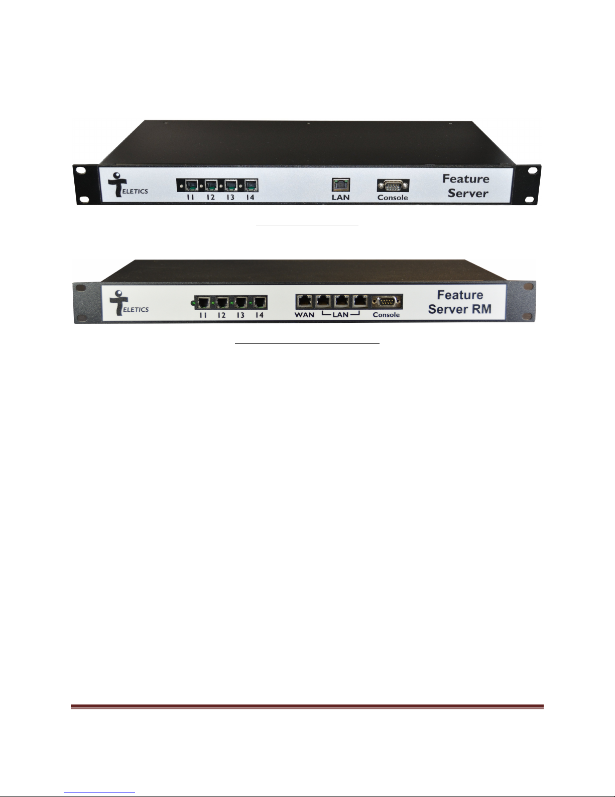
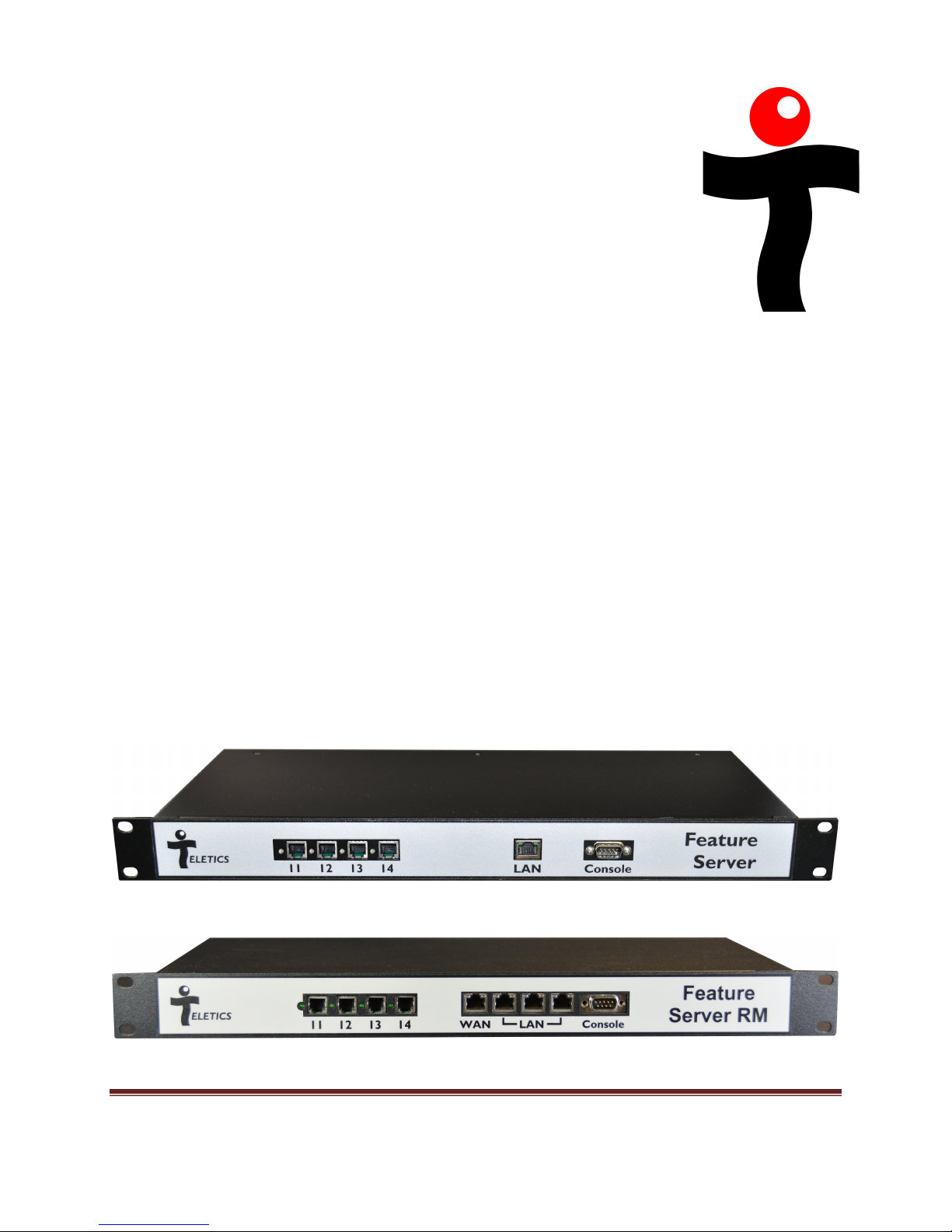
Installing the Teletics Feature Server RM
Single LAN port Model
4 Port Integrated Router Model
The Teletics Feature Server RM can be added on any available RJ-45 port on a w*intercom system. This
unit should be connected to the system using an Ethernet cable included with the unit.
The only other plug on the unit is for +12VDC (for a single LAN port model) or +24Vdc for 4 port
integrated router model. A power adapter is included with the unit for use with the Teletics Feature
Server RM.
In the case of the 4 Port Integrated Router Model, being used in a “stand alone” system, without the
Teletics Harness Web Portal Service, only the rightmost LAN port is active. All the other RJ45 ports are
disabled.
w*intercom programming
w*intercom radios are able to take advantage of all of the functions of the Feature Server RM. There is
nothing to set during programming w*intercoms to use the Feature Server RM.
A relatively quick way to check if the w*intercom units that you are currently working with are working
correctly is to apply power to the w*intercom units, and check to see if you have dial tone when you lift
the phone receiver.
A w*intercom unit that cannot connect to a Feature Server RM will give you a verbal indication of
“Device Not Registered” at the handset.
Teletics Feature Server RM Installation and User Guide – Rev 2.0 – Jul 18, 2017 Page 4
Page 5

Powering Up
The Teletics Feature Server RM does not require any kind of initial programming or setup. Once power
is applied, it will need about 60 seconds to initialize. After this time has elapsed, you should notice that
all units register with the unit and any phone that is picked up will give normal dial tone.
w*intercom units check for the presence of a Feature Server RM every 60 seconds. Since all units may
be powered up at different times, some w*intercom units may appear to register at different times, but
in all cases they should register in about a minute or less.
The four FXO ports provided with the initial Feature Server RM program routes calls in the following
manner:
FXO port 1 (Leftmost port) <-> w*intercom Phone 11
FXO port 2 <-> w*intercom Phone 12
FXO port 3 <-> w*intercom Phone 13
FXO port 4 (Rightmost port) <-> w*intercom Phone 14
Additional Dialing Features
The Teletics Feature Server RM provides the following additional features to all users on the w*intercom
system:
Individual Page
The Individual Page feature allows any user on the system to send a page to any other single
w*intercom unit in the system.
Page All But Caller
The Page All But Caller feature provides paging to the paging port of each of the w*intercom in
the system, except the paging port on the wintercom making the page.
All Page
The All Page feature provides paging to the paging port of each of the w*intercom in the
system.
All Call
The All Call feature provides the ability to have the phone ports on all of the w*intercoms,
except the originating phone, to ring until one is answered.
Teletics Feature Server RM Installation and User Guide – Rev 2.0 – Jul 18, 2017 Page 5
Page 6

Conference Call
The Conference Call feature provides a simple conference call capability. There are 3
conference rooms provided per system. Users gain access through an interactive voice response
(IVR) based conference facility when they dial one of the conference call codes on their phone.
Dial Commands
A standard w*intercom allows the following two digit dial sequences:
XX where XX = 11,12,13 … 30 Dials Phone 11,12,13…30
NOTE1
ZZZ
YYYYYYY where YYYYYYY = 7 (or 10) digit phone number Dials phone number through
FXO port on Feature Server RM
(available on phones
*XX where XX = 11,12,13 … 30 Individual Page Phone 11,12,13…30
*88 (Page All But Caller) Page all BUT the calling wintercom
where ZZZ = 101, 102, 103, 104… 120 Dials Phone 101, 102, etc.
11, 12, 13, 14 ONLY)
*99 (Page All) Page All (w*intercom stations)
99 Ring All until one Phone answers
*5X where X = 0, 1 or 2 Join Conference “Room” 0,1, or 2
Note 1: Both 2 digit and 3 digit dialing is standard with Harness firmware version. Optional dial plan
load for standalone version, which replaces the two digit dial plan. Contact Teletics Support for details.
Dial Command Examples
Individual Page - If you are at Phone 12, and you want to send a page message to only the person at
Phone 11, you would pick up your phone and dial *11. You will hear a beep indicating you may now
talk. You are now connected to the PA speaker located at Phone 11. Remember that anything you now
say will come out the PA Speaker located at unit 11 until you hang up. You talk until you are finished
and hang up.
Page All But Caller – If you dial *88 from any wintercom unit, all of the PA Speakers EXCEPT the PA
Speaker of the wintercom you are calling from will play a tone, and then anything you say will be sent
out over the PA speakers of all units except the wintercom you are dialing from. You talk until you are
finished and hang up.
Teletics Feature Server RM Installation and User Guide – Rev 2.0 – Jul 18, 2017 Page 6
Page 7

All Page - If you want to send a page to the entire camp, including the unit you are using, you can pick
up any phone and dial *99 and wait for the beep to start talking. You may continue to talk for as long as
you like. Again, you talk as long as you like and hang up to stop the page. Dialling this number tends to
create a lot of feedback, so this is generally not used, except if the PA Speaker at the station being used
is a considerable distance away, or for emergency purposes.
All Call - If you want to talk to anyone on the site, you can pick up your phone, dial 99, and all the
phones in the system will ring until the first person picks up. You can then talk to whoever answered
first and all of the phones will stop ringing.
Conference Call – If you want to set up a conference call, each person needs to know the “conference
room” where the meeting is to be held. Options are *50, *51, or *52. When anyone at the site dials in
to a particular room, they will hear if they are the first participant, and then each additional person
entering the room will cause the participants already in the room to hear a beep.
Let’s pick room 0 for example.
Everyone who wishes to join the conference would pick up their phone and dial *50. Any user already
on the system will hear a beep as others enter the conference, and the first person in the conference
room hears a message that they are the first participant.
The Conference Call feature on the Teletics Feature Server RM is designed to be simple and effective.
There are no passwords to set up or administration required. Participants are simply announced by a
beep as they join and leave. Every Conference room is available at any time to any user.
Teletics Feature Server RM Installation and User Guide – Rev 2.0 – Jul 18, 2017 Page 7
Page 8

Troubleshooting
If the w*intercom unit provides dial tone when you pick up
the receiver, it has correctly registered with a Feature Server
RM.
If you understand computer networking and just want to test
if the Teletics Feature Server RM is present on the network,
you may ping it at 169.254.5.200 for a w*intercom network.
Once the Teletics Feature Server RM has power applied and
has initialized, the services are available to any w*intercom
that has been programmed to register with the Feature Server
RM.
If only some of the w*intercom units register, you should
reprogram the units that are not registering, ensuring they are programmed with the correct GroupID
and try them again. Teletics TUtil w*intercom software can assist you in determining the settings are
incorrect with the radios that are not working correctly with the system under test.
Additionally, unless you are using the Teletics Harness Web Portal to manage your wintercom fleet, you
need to ensure that the ONLY RJ45 that is being used on the Feature Server RM is the one closest to the
Console port (on the right hand side).
Accessing the Feature Server RM web interface
If you have a network connection available to the Feature Server RM, you can access it using the
following URL:
http://169.254.5.200:3315 (w*intercom Systems)
The default user id is “admin”, and the default password is “teletics”.
The initial setup provided by Teletics provides a working system with intercom dialing, paging,
conference calling and features typically used by our customers. However, if a customer is interested in
custom calling features, Teletics can provide this on a project basis, or if the customer wants to learn on
how to develop their own additional features, they can do so, by downloading the Teletics “Feature
Server Handbook”, available on the Teletics support website.
Teletics Feature Server RM Installation and User Guide – Rev 2.0 – Jul 18, 2017 Page 8
Page 9

Teletics Feature Server RM Specifications
Data Connector Standard RJ-45
FXO Ports 4 x Standard RJ11
Power Required 12 VDC @ 2A (1 LAN version)
24 VDC @ 2A (4 port Router version)
Operating Temperature Range -20C to +50 C / -5F to +125 F
Dimensions 1U 16.9” x 8.0” x 1.75”
Shipping Weight, including packaging 3.4 kgs / 8.1 lbs
Warranty Statement:
Teletics warrants the Teletics Feature Server RM to be free of defects of materials and workmanship for a period of
one year after purchase by the original owner.
Teletics will repair or replace, at its option, any Teletics Feature Server RM unit that fails to perform the task it was
designed for under normal use, provided the Teletics Feature Server RM is returned, at the cost of the owner, to
Teletics, or one of Teletics Authorized Repair Facilities in the United States or Canada. Items returned for repair
must be accompanied with a problem description and original proof of purchase, such as an invoice.
Any operation of the Teletics Feature Server RM outside of specified temperatures, specified input power,
environment, or in a manner specified as harmful in this manual will void any warranty. Additionally, any
attempted repair or dismantling of any Teletics product, in any way, will void all warranties.
In no event shall Teletics liability exceed the original purchase price of the product from direct, indirect, special,
incidental, or consequential damages from the use, or misuse of this product.
Intended Use Statement:
This product is intended for industrial communications use. Installation is to be performed by qualified
Technicians.
Teletics Feature Server RM Installation and User Guide – Rev 2.0 – Jul 18, 2017 Page 9
 Loading...