

Page 1
TeleTek
SIREN
SR120
INSTALLATION GUIDE
Page 2
GENERAL INFORMATION
SR 120 is an outdoor self-protected siren basically intended to emit sound signals when
triggered by an alarm system. It also has a light indicator a flash lamp, which has two
options halogen or sulphide. SR 120 is on a circuit board placed in a box with a cover. The box
cover is either ABS or polycarbonate of high toughness and modern design. Inside there is
an additional second metal cover (inner cover). SR 120 can be installed both outdoors and
indoors. The audio frequency of the siren signal is within the range of 1.8 3.3 kHz.
The universal nature of operation makes SR 120 compatible with all types of alarm systems,
which provide a power supply and drive of 12 V.
Product Identification
SR 120 - Automatically blocking siren with sulphide flash lamp
SR 120B - Automatically blocking siren with halogen flash lamp
The siren comes in several options depending on the type of lamp, type and design of the
circuit board.
INSTALLATION
Initial Preparation
Dismantle the box before installing the siren. First remove the outer and then the inner
cover of the box. The flash lamp becomes accessible immediately after the outer box is
removed. It must not be touched by hand. Carefully, without touching it, remove the inner
cover. Keep the screws and remember that the longer ones belong to the outer cover and
the shorter to the inner cover.
Choosing a Mounting Place
It is important to choose an appropriate place to mount the siren. A hood or a balcony is
suitable in order to avoid direct impact of outdoor weather conditions on the siren. The spot
should exceed the height of 3 m, thus making it difficult for external access attempting to
eliminate the siren.
Mounting
Use the profile board on the back of the cardboard box to position and drill the necessary
openings (three) on the wall where the siren is going to be mounted.
Prior to mounting the siren box on the wall, the cable bracing for attaching the battery must
be prepared. Therefore, pass it through the opening specially made for the purpose at the
bottom of the box without closing it. At that, the smooth side of the bracing must remain on
the outer side and the indented side must touch the battery. The lash of the bracing remains
at the outer end of the box and the opening
at the inner end. The battery terminals must
be at the inner side. Fix the box to the wall
with the help of the three screws.
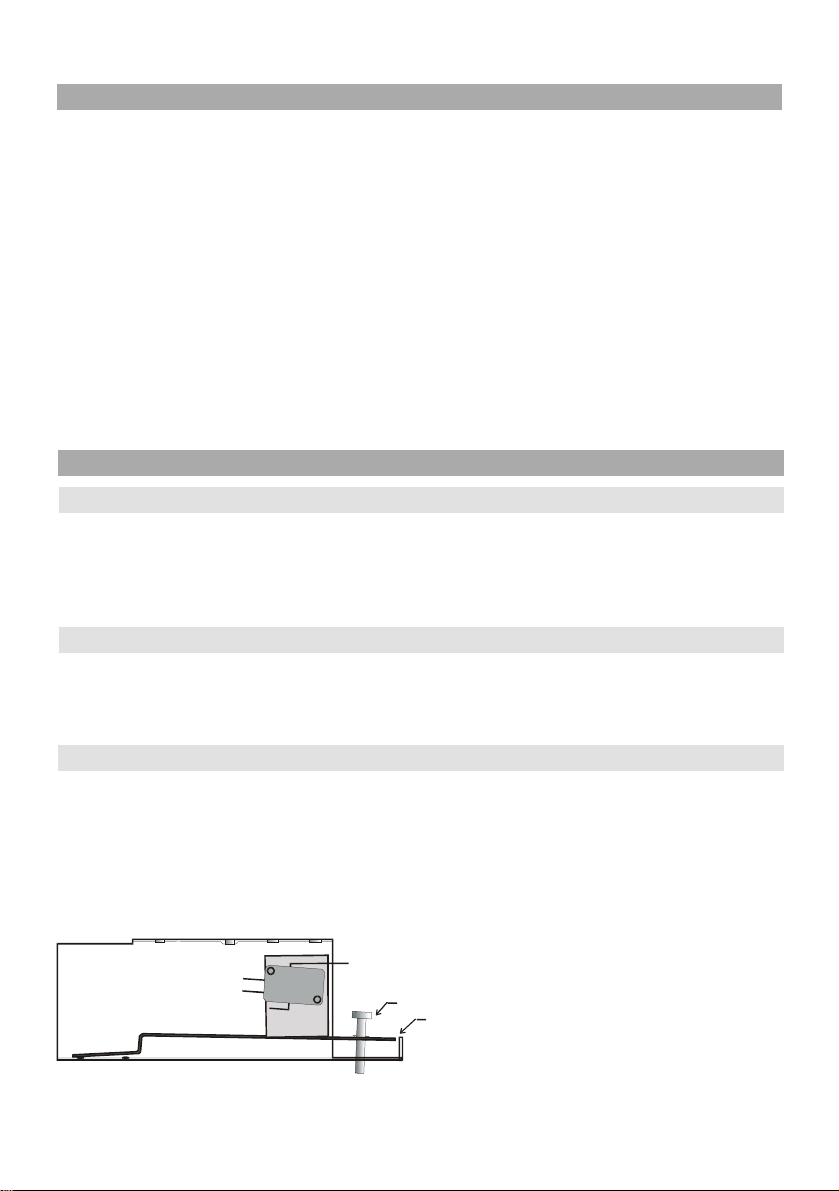
Next adjust the tamper switch. This is done
with the help of a screw to regulate the strip
so it remains at a height level of rim 2 of
the metal box. See Figure 1.
fig.1
Page 3

This adjustment is necessary so as to compensate the surface roughness of the wall.
Notice! Make sure the No. 1 regulating screw rests on a solid base to avoid any
deviation from the set adjustment!
Configuration
There are two types of connections depending on the drive. Therefore, your siren must be
properly configured prior to connecting the terminals. This is determined by the position of
the J1 jumper. At that, in the case of a double wire connection (no blocking signal) the
jumper must be switched on. With a triple wire connection (with positive blocking signal)
the jumper must remain in switched off position left in its place, switched to one leg.
Connection
Before applying power to the siren, the alarm system tamper zone can be connected to the
two wires leading to the siren tamper switch. Connection is done according to the J1
jumper position as determined when configuring.
+12V
Control Panel
SIREN
Control Panel
Control Panel
GND
PGM
GND
GND
SIREN
fig.2
fig.3
fig.4
SR120
SR120
SR120
Triple wire connection
Connect the power of the alarm system to the
GND and +12V terminals. (Fig. 2)
Connect the +12V blocking signal of the alarm
system to the BLOCK terminal.
The siren is activated when the BLOCK terminal
signal is suspended.
Double wire connection
Connect the alarm system minus power wire to
the GND terminal. (Fig. 3)
Connect the +12V positive blocking signal of
the alarm system to the +12V terminal.
The siren is activated when the +12V terminal
signal is suspended.
Double wire connection without Battery
Connect the alarm system minus power wire
to the GND terminal. (Fig. 4)
Connect the +12V driving signal of the alarm
system to the +12V terminal.
The siren is activated when the +12V driving
signal appears.
The Jumper J1 must be removed.
Page 4

Placing the Battery
It should be borne that when placing the battery only one of the two possible options to
position it is correct. For security reasons (external inaccessibility to the battery terminals,
in order not to eliminate the back-up power supply source of the siren) it is good for the
terminals to be at the inner part of the box. Attach the battery to the box using the cable
bracing.
Notice! The cable shoes should be connected to the battery. Observe the
black and red polarity. The siren has protection, which will burn out if
these are switched around. The protection can be restored at the company
service office only.
In case of Double wire connection without Battery ensure the battery
cables are safeguarded.
Completing Installation
Close the box with the inner cover first and then the outer cover. Fix the inner cover with the
shorter screws. For the outer cover use the remaining two screws.
TECHNICAL SPECIFICATIONS OF THE SIREN
Electric Parameters
Power supply 13.5 V 13.8 V
Quiescent current 30 mA
Alarm current at 12V max 1,6 A
Back-up battery 2,1 (2,3) Ah/12 V
Acoustic parameters
Audio frequency 1,8 3,3 KHz
Audio output 120 dB per 1m
Environment
Operating temperature -25oC - +55oC
Mechanical features
Dimensions 205x170x90 mm
Please note:
Teletek Electronics are always endeavouring to improve quality and specification
of all its products and may alter or amend this product and instructions without
notice.
& %!
 Loading...