

Page 1
TECHNICAL SPECIFICATIONS / CARACTERÍSTICAS TÉCNICAS / ТЕХНИЧЕСКИ ХАРАКТЕРИСТИКИ
General Description
SensoMAG MCP50 is a manual call point,
designed to work with conventional fire
panels.
Working Principle
In stand-by mode, the resettable (flexible)
call point element is in a middle position.
The call point is powered off and the LED is
off.
When pressed on, the resettable element is
moving down and a color strip is shown on
at its upper side. The call point is powered
on and the LED is on - this is a “Fire alarm”
condition.
The resetting of the flexible element back in
stand-by mode is done with the special key
tool - fix the long side of the tool at the call
point bottom side and push up until flexible
element moves up in middle position (a click
is heard).
Testing the Call Point Operation
Isolate the fire alarm system before testing.
Use the special tool to test the call point
operation function ability - insert the tool in
the “Test” hole and push up to test. The tool
moves the flexible element up and thus
operates the call point. The LED will light up
while the call point is in test mode.
English
Installation Instructions
Descripción general
SensoMAG MCP50 es un pulsador de alarma
de incendio, destinada al funcionamiento en
sistemas de alarma de incendios
convencionales.
Principio de funcionamiento
En modo de reposo (estado no activado), el
elemento de trabajo está en posición media. A
través de la alarma de incendios no circula
corriente eléctrica y el diodo luminiscente está
apagado.
Cuando se aprieta el elemento de trabajo, dicho
elemento se desplaza hacia abajo, aparece una
franja iluminada en su parte superior y a través
de la alarma de incendios circula corriente
eléctrica, encendiéndose el diodo luminiscente:
estado de Alarma.
La recuperación de la alarma de incendios en
modo de espera se realiza con la ayuda de la
llavecita, introduciendo su parte larga en la
abertura de prueba (por la parte inferior de la
alarma de incendios), apretando hacia arriba,
hasta que el elemento de trabajo retorne a la
posición media (neutral) (se oye un chasquido).
Prueba de la capacidad de trabajo
Separe el panel de incendios antes de proceder
a efectuar la prueba del pulsador manual. La
prueba de la capacidad de trabajo se efectúa
por medio de la llave adjunta: coloque la parte
larga de la llave en la abertura de prueba y
apriete hacia arriba. La llave desplaza el
elemento de trabajo hacia arriba, simulando de
este modo el estado de Alarma. El diodo
luminiscente rojo se iluminará durante largo
tiempo mientras que se esté realizando la
prueba.
Español
Instrucción para la instalación
Общо описание
SensoMAG MCP50 е ръчен
пожароизвестител, предназначен за работа в
конвенционални пожароизвестителни
системи.
Принцип на действие
В дежурен режим (незадействано състояние)
работният елемент е в средно положение.
През пожароизвестителя не протича ток и
светодиодът е изгасен.
При натискане на работния елемент той се
измества надолу, показва се оцветена ивица
в горната му част, през пожароизвестителя
протича ток и светодиодът светва - режим
“Тревога”.
Възстановяване на пожароизвестителя в
дежурен режим се извършва с помощта на
специализиран инструмент (ключ) - дългата
му част се поставя в отвора за тест (от
долната страна на пожароизвестителя) и се
натиска нагоре докато работният елемент се
върне в средно (неутрално) положение (чува
се изщракване).
Тестване за работоспособност
Изолирайте пожарния панел преди да
преминете към тестване на ръчния бутон.
Тестване за работоспособност се извършва
чрез специализирания инструмент поставете дългата страна на ключа в отвора
за тест и натиснете нагоре. Ключът
придвижва работният елемент нагоре, като
по този начин симулира режим “Тревога”.
Червеният светодиод свети продължително
по време на теста.
Български
Инструкция за инсталиране
Indoor Use /
Montaje interno /
Вътрешен монтаж
18020872; RevA; 04/2017
SensoMAG MCP50
Conventional manual call point
Teletek Electronics JSC
Address: 14A Srebarna Str,
1407 Sofia, Bulgaria
EN 54-11:2001
EN 54-11:2001/A1:2005
Type А
DoP No: 091
1293
17
EVPU: N.B.1293
1293-CPR-0545
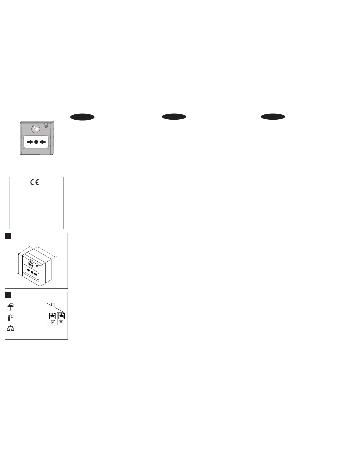
90mm
90mm
56mm
Dimensions / Dimensiones /
Размери
!
IP40
-10°C ÷ +60°C
≤150g
Installation / Instalación /
Инсталиране
!
Operating voltage . . . . . . . . . . . . . . . . Voltaje de funcionamiento . . . . . . . . . . . . . Работно напрежение. . . . . . . . . . . . . . . 9÷30VDC
Nominal operating voltage . . . . . . . . . . Tensión nominal de funcionamiento . . . . . Номинално работно напрежение. . . . . 24 VDC
Current consumption in alarm state. . . Corriente eléctrica en estado de Alarma . . Ток в режим “Тревога”. . . . . . . . . . . . . . 23mA/15V; 38mA/24V; 48mA/30V
2 2
Installation wires . . . . . . . . . . . . . . . . . Cables de conexión . . . . . . . . . . . . . . . . . . Свързващи проводници . . . . . . . . . . . . 0.4mm ÷ 2.0mm
Relative humidity . . . . . . . . . . . . . . . . . Humedad relativa . . . . . . . . . . . . . . . . . . . Относителна влажност . . . . . . . . . . . . . ≤93%@+40°C
Material (plastic), color. . . . . . . . . . . . . Material (plástico), color . . . . . . . . . . . . . . Материал (пластмаса), цвят. . . . . . . . . ABS, red/rojo/червен
Type of the frangible element . . . . . . . Tipo del elemento de trabajo . . . . . . . . . . . Вид на работния елемент. . . . . . . . . . . resettable/rearmable/възстановяем
Indication “Fire alarm” . . . . . . . . . . . . . Indicación del régimen de Alerta . . . . . . . . Индикация на режим “Тревога” . . . . . . red LED/diodo luminiscente rojo/червен LED
This manual is subject to change without notice! / ¡El fabricante se reserva el derecho de realizar cambios sin notificación previa! / Производителят си запазва правото на промени без предизвестие!
Page 2
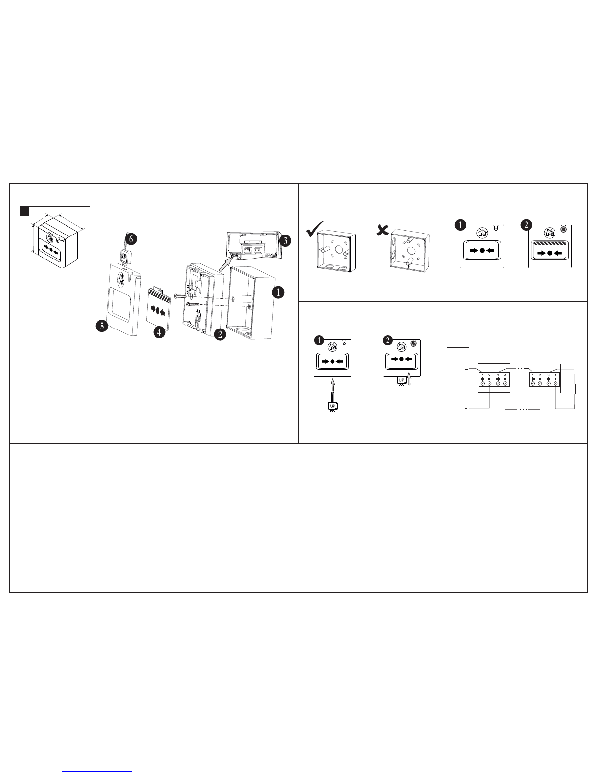
Installation Instructions
1. Pick up the cover and take out the kit elements.
2. Mount the box as observe the knockout holes - never locate them
at left or right side.
3. Take the cover and with the special tool remove the carrier unit use the short side of the tool. As observe the location of the
“Up”mark to be in front, fix the short side to the holes at the upper
side of the call point. Press down and pull out the cover from the
carrier unit.
4. Remove the flexible element from the carrier unit - pick up the
bottom side of the element and pull out.
5. Connect the installation wires to the call point terminals - see the
connection diagram.
6. Place the carrier unit over the mounting box and use the supplied
in the kit screws to fix the parts together.
7. Place back the flexible element to the carrier unit.
8. Mount the cover.
9. Test the call point functionality.
Инструкции за инсталиране
1.Свалете капака на ръчния бутон и извадете плика с
допълнителни елементи.
2. Монтирайте основата към стената, като позиционирате
отворите за щуцери отгоре и отдолу - не монтирайте основата с
отворите настрани.
3. С помощта на ключа свалете капака от носещата рамка поставете късата страна на ключа в отворите от горната страна
на бутона, като съблюдавата марката “UP” да е отпред.
Натиснете надолу, за да избутате палеца и свалете капака.
4. Свалете работният елемент от носещата рамка - повдигнете
долната му страна и издърпайте.
5. Свържете бутона към пожарната инсталация.
6. Използвайте винтовете от комплекта с допълнителни
елементи, за да фиксирате носещата рамка към монтажната
основа.
7. Монтирайте обратно работния елемент към рамката.
8. Монтирайте капака.
9. Тествайте ръчния бутон за работоспособност.
STRUCTURE / ESTRUCTURA / СТРУКТУРА
Surface mounting position /
Disposición durante el montaje /
Разположение при монтиране
Testing the operation /
Prueba de la capacidad de trabajo /
Тестване за работоспособност
Push upwards - the LED
must light on / Presione
hacia arriba: el diodo LED
deberá estar iluminado /
Натиснете нагоре светодиода трябва да
свети
LED Indication /
Indicación LED /
LED Индикация
Stand-by mode /
Estado de reposo /
Дежурен режим
Fire alarm mode /
Estado de Alarma /
Режим Тревога
Connection to a fire alarm panel /
Conexión a un panel de alarma de incendios/
Свързване към пожароизвестителен панел
(1) - surface mounting box;
(2) - carrier unit;
(3) - PCB with terminals (mounted
on the back of the carrier unit);
(4) - resettable (flexible) element;
(5) - cover;
(6) - tool for opening, testing and
resetting of the flexible element in
stand-by mode (use the tool as
shown on the picture - the “UP”
mark must be in front).
(1) - base de montaje en pared;
(2) - marco de soporte;
(3) - circuito con terminales
(montado en la parte opuesta del
marco de soporte);
(4) - elemento de trabajo (flexible);
(5) - tapa;
(6) - llave para abrir, probar y
restablecer el elemento de
funcionamiento en estado de
reposo (utilice la herramienta,
como se ha indicado en el
esquema: la marca “UP” debe
estar adelante).
(1) - основа за стенен монтаж;
(2) - носеща рамка;
(3) - платка с клеморед
(монтирана от обратната страна
на носещата рамка);
(4) - работен (гъвкав) елемент;
(5) - капак;
(6) - ключ за отваряне, тестване
и възстановяване на работния
елемент в дежурен режим
(използвайте инструмента както
е показано на схемата - надпис
“UP” трябва да е отпред).
The “UP” mark must be in
front / La marca “UP”
deberá estar adelante /
Надпис “UP” трябва да е
отпред
Instrucción para la instalación
1. Retire la tapa del botón manual y saque la bolsa que contiene los
elementos adicionales.
2. Instale la base hacia la pared, posicionando las aberturas de las
válvulas de seguridad arriba y abajo: no monte la base con las
aberturas hacia un lado.
3. Con la ayuda de la llave, retire la tapa del marco de soporte,
coloque la parte corta de la llave en las aberturas de la parte
superior del botón, observando que la marca UP esté por delante.
Apriete hacia abajo para empujar el pulgar y retire la tapa.
4. Retire el elemento de trabajo del marco de soporte: levante su
parte inferior y tire hacia Ud.
5. Conecte el pulsador a la instalación de incendios.
6. Utilice los tornillos del kit de elementos adicionales para fijar el
marco de soporte a la base de montaje.
7. Instale nuevamente el elemento de trabajo hacia el marco.
8. Instale la tapa.
9. Pruebe la capacidad de trabajo del pulsador manual.
90mm
90mm
57mm
!
+
-
+
-
Fire Alarm Panel
MCP 50 MCP 50
EOL
 Loading...