

Page 1
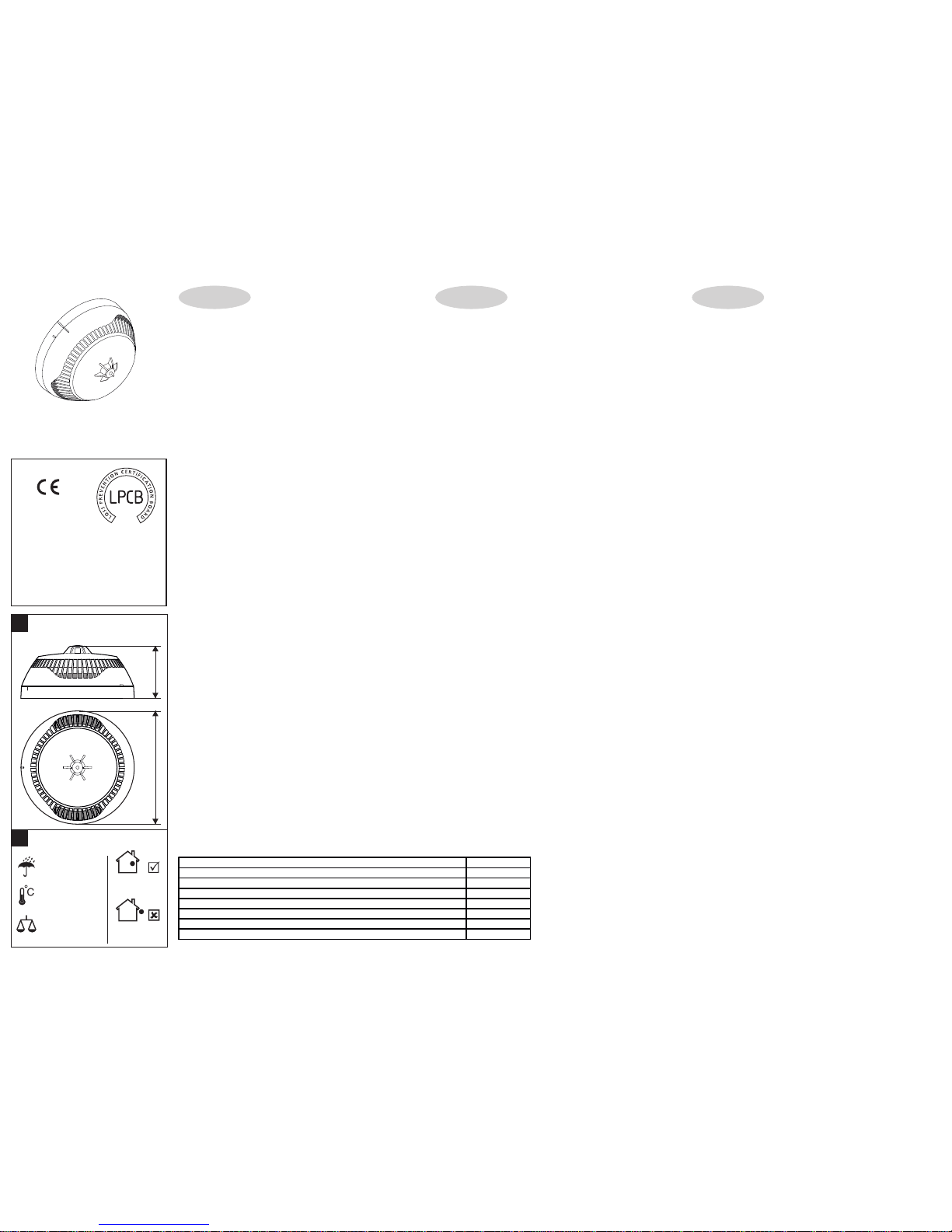
Indoor use /
Montaje interno /
Вътрешен монтаж
Outdoor use
Montaje externo /
Външен монтаж /
Operating Voltage Range. . . . . . . . . . . . . . . . . . . . . . . . . Voltaje de alimentación. . . . . . . . . . . . . . . . . . . . . . . . . . . . . . . . . . Захранващо напрежение . . . . . . . . . . . . . . . . . . . . . . . . . . . . . 15 - 32VDC (Nom. 27VDC)
Consumption in quiescent state, no communication . . . . Consumo en estado sin activar, sin comunicación. . . . . . . . . . . . . Консумация в незадействано състояние, без комуниакция. . < 160μA@27VDC
Consumption in quiescent state, with communication . . . Consumo en estado sin activar, con comunicación . . . . . . . . . . . . Консумация в незадействано състояние, с комуниакция. . . . < 200μA@27VDC
Consumption in alarm state, with communication . . . . . . Consumo en estado de alarma, con comunicación . . . . . . . . . . . . Консумация в алармено състояние, с комуникация . . . . . . . . 6.5mA
Class (in accordance with EN54-5) . . . . . . . . . . . . . . . . . Clase (en conformidad con EN54-5) . . . . . . . . . . . . . . . . . . . . . . . Клас (в съответствие с EN54-5) . . . . . . . . . . . . . . . . . . . . . . . . A1/R
Sensitivity level (in accordance with EN54-7*) . . . . . . . . . Nivel de sensibilidad (en conformidad con EN54-7*). . . . . . . . . . . Ниво на чувствителност (в съответствие с EN54-7*)
- High/ *Normal/ Middle/ Low. . . . . . . . . . . . . . . . . . . . - Alto/ *Normal/ Medio/ Bajo . . . . . . . . . . . . . . . . . . . . . . . . . . . - Висока/ *Нормална/ Средна/ Ниска
Output in alarm state at terminal RI (terminals 4/ 1). . . . . Corriente eléctrica en estado de alarma del RI (terminales 4/1) . . Ток в алармено състояние на клема RI (клеми 4/ 1). . . . . . . . 7.5 mA (max)/ 7.5V
2 2
Wire Gauge for terminals . . . . . . . . . . . . . . . . . . . . . . . . . Sección del cable utilizado . . . . . . . . . . . . . . . . . . . . . . . . . . . . . . . Сечение на използвания проводник. . . . . . . . . . . . . . . . . . . . . 0.4mm ё 2.0mm
Relative humidity resistance. . . . . . . . . . . . . . . . . . . . . . . Resistencia a humedad relativa . . . . . . . . . . . . . . . . . . . . . . . . . . . Устойчивост на относителна влажност . . . . . . . . . . . . . . . . . . (93 ± 3)% @ 40°C
TECHNICAL SPECIFICATIONS / CARACTERÍSTICAS TÉCNICAS / ТЕХНИЧЕСКИ ХАРАКТЕРИСТИКИ
SensoIRIS M140
English
Español
Български
SensoIRIS M140 is аn addressable combined (optical-smoke and heat)
detector designed for installing in addressable fire alarm systems supporting
TTE communication protocol. The detector is powered on from the panel
and can be controlled via the communication protocol.
The detector SensoIRIS M140 is compatible with fire base B124.
Installation Instructions
1. Choose the proper place for installation of the fire detector. Refer to
the given installation instructions. Note: Do not install the detector near
sources of steam, condensation or smoke and close to natural heat sources.
2. If you want to “lock” the detector to the base remove the little “tooth”
on the top of the locking mechanism (located in the narrow part).
3. Mount the fire base on the ceiling of the protected premises using fixings
according the mounting surface.
4. Connect the detector base to the fire panel using the wiring diagram.
ATTENTION: Disconnect the loop power before installing the detector!
5. Insert the detector into the base and rotate clockwise until it drops into
place - the short mark on the base fits with that on the detector body.
Continue to rotate the detector until the detector mark coincides with the
long mark on the base - a click is heard.
6. Test the detector for proper operation and LED indication.
ATTENTION: The blinking of the two LEDs can be managed from the control
panel (ON/ OFF).To turn the blinking on/ off you have to be a User with
Access control level 3.
Choose in consecutiveness from the control panel: System - Programming -
Devices - Loop. Find the installed detector, as enter address, loop and zone
number - the panel automatically will recognize the type of the detector.
Choose the button MORE to enter in the additional settings menu. The
blinking of LEDs is turned on/ off with pressing the ON/OFF button in the
“Led Blink” field.
7. If the detector has been locked to the base, when open it for a service
schedule maintenance and cleaning you have to use a plain screw-driver.
Light press with the screw-driver into the base opening and at the same time
rotate the detector head counter-clockwise.
Warranty
All detectors carry on a warranty valid from the date of manufacture. The
date of manufacture can be checked by the code sticker label on the back of
the detector. The date is printed with white numbers into a black area.
The first two numbers represent the year and the last two - the month. For
example: The date code “15 07”, means the detector is manufactured in
July, 2015.
To return goods for warranty service, please contact with your local
distributer for details.
SensoIRIS M140 – Detector analógico combinado (de humo óptico y de
temperatura). El detector está destinado a utilizarse en sistemas de alarma
analógicos, que mantienen el protocolo de comunicación TTE. El detector
recibirá alimentación del panel y podrá ser controlado mediante el protocolo
de comunicación.
El detector SensoIRIS M140 es compatible con la base B124.
Instrucciones de instalación
1. Seleccione un lugar apropiado para instalar el detector. Siga las
instrucciones que se han dado para la instalación. Observación: No instale
el detector cerca de fuentes de calor naturales, por ejemplo, encima de
cocinas, hornos o chimeneas.
2. Si desea bloquear el detector en la base, retire la pestaña de la punta
del mecanismo de cierre (en la parte estrecha).
3. Instale la base en el techo del local, seleccionando los tornillos y los
tacos según la superficie de montaje.
4. Realice el montaje eléctrico, según el esquema adjunto.
ATENCIÓN: ¡Desconecte la alimentación del lazo antes de montar el
detector!
5. Coloque el detector en la base y hágalo girar en el sentido de las agujas
del reloj hasta que se introduzca en los canales guía: el marcador corto de
la base coincide con el del detector. Siga girando, hasta que el marcador del
detector coincida con el marcador largo de la base: se oirá un chasquido.
6. Pruebe si el detector y la indicación LED funcionan correctamente.
ATENCIÓN: El parpadeo de los diodos LED del detector podrá conectarse y
desconectarse del panel de control. Para conectar/desconectar el parpadeo
de los diodos LED, Ud. deberá ser usuario con nivel de acceso 3.
Seleccione sucesivamente en el panel: Sistema – Programar – Dispositivos
– Lazo. Encuentre el detector instalado, determinando la dirección, el
número del lazo y de zona: el panel reconocerá automáticamente el tipo del
dispositivo. Seleccione el pulsador MÀS para entrar en el menú de ajustes
adicionales. El parpadeo del diodo LED se conectará/desconectará al
presionar el pulsador CONECT./DESCONECT. en el campo “Parpadeo del
diodo LED”.
7. Si el detector está bloqueado en la base, para abrirlo con el propósito
de su limpieza y mantenimiento deberá utilizar un destornillador apropiado.
Apriete ligeramente con el destornillador en la abertura de la base, y,
simultáneamente, haga girar el detector en el sentido inverso al de las
agujas del reloj.
Garantía
Todos los detectores poseen una garantía válida desde la fecha de
fabricación. La fecha de fabricación se ha indicado en la pegatina que ha
sido pegada sobre el dorso del detector, con cifras blancas a fondo negro:
AA MM. Las primeras dos cifras representan el año, y las últimas dos cifras
el mes de fabricación. Ejemplo: “15 07” significa fecha de fabricación julio de
2015.
En caso de devolver productos para un servicio de garantía, diríjase a su
distribuidor regional.
SensoIRIS М140 е адресируем комбиниран (оптично-димен и
температурен) детектор предназначен за използване в адресируеми
пожароизвестителни алармени системи, поддържащи комуникационен
протокол TTE. Детекторът получава захранване от панела и може да
бъде контролиран чрез комуникационния протокол.
Детектор SensoIRIS M140 е съвместим с основа B124.
Инструкция за инсталиране
1. Изберете подходящо място за монтаж на детектора. Следвайте
дадените инструкции за инсталиране. Забележка: Не инсталирайте
детектора в близост до източници на пара, дим, прах или топлина печки, камини и т.н .
2. Ако желаете да “заключвате” детектора към основата отстранете
зъбчето на върха на заключващия механизъм (в стеснената част).
3. Монтирайте основата на тавана на помещението, като подберете
винтове и дюбели според монтажната повърхност.
4. Извършете електрически монтаж съгласно приложената схема.
ВНИМАНИЕ: Изключете захранването на контура преди да
монтирате детектора!
5. Поставете детектора в основата и го завъртете по посока на
часовниковата стрелка до попадане в направляващите канали - късият
маркер на основата съвпада с този на детектора. Продължете да въртите
докато маркера на детектора съвпадне с дългия маркер на основата чува се щракване.
6. Тествайте детектора за правилна работа и светлинна индикация.
ВНИМАНИЕ: Мигането на светодиодите на детектора може да се
включва и изключва от контролния панел. За да включите/ изключите
мигането на светодиодите трябва да сте Потребител с Ниво на достъп 3.
Изберете последователно от панела: Система - Програмиране -
Устройства - Кръгови. Намерете инсталирания детектор, като зададете
адрес, номер на кръг и зона - панела разпознава автоматично типа на
устройството. Изберете бутон Друго, за да влезете в менюто за
допълнителни настройки. Мигането на светодиода се включва/ изключва
с натискане на бутон ВКЛ./ИЗКЛ. в поле “Мигане на светодиода”.
7. Ако детекторът е заключен към основата, за да го отворите за
почистване и поддръжка трябва да използвате подходяща отвертка. Леко
натиснете с отвертката в отвора на основата и едновременно с това
завъртете детектора обратно на часовниковата стрелка.
Гаранция
Всички детектори притежават гаранция валидна от датата на
производство. Датата на производство е изписана върху стикера,
залепен на гърба на детектора, с бели цифри на черен фон. Първите две
цифри представляват годината, а последните две - месеца на
производство. Пример: “15 07”, означава дата на производство Юли
2015.
За да върнете изделия за гаранционен сервиз се обръщайте към вашия
регионален дистрибутор.
Installation Instruction Instrucciones de instalación Инструкция за инсталиране
ATTENTION: Read carefully this installation Instructions before
installing the device! This manual is subject to change without
notice!
ATENCIÓN: ¡Lea atentamente las instrucciones antes de proceder
a instalar el detector! ¡El fabricante se reserva el derecho de
realizar cambios sin notificación previa!
ВНИМАНИЕ: Прочетете внимателно инструкцията преди да
пристъпите към инсталиране на детектора! Производителят
си запазва правото за промени без предизвестие!
Teletek Electronics JSC
Address: 14A Srebarna Str,
1407 Sofia, Bulgaria
EN 54-5: 2000/ A1: 2002,
EN 54-7: 2000/ A2: 2006
Detector Class A1/R
Intelligent analogue addressable
fire alarm heat and
optical smoke detector
DoP No: 057
0832-CPD-2201
0832
13
without base/
peso sin base incluida /
без основа
Essential characteristics Performance
Performance under fire conditions Pass
Operational reliability Pass
Durability of operational reliability and response delay: temperature resistance Pass
Durability of operational reliability: humidity resistance Pass
Durability of operational reliability: shock and vibration resistance Pass
Durability of operational reliability: corrosion resistance Pass
Durability of operational reliability: resistance to ingress Pass
18020723, RevE, 11/ 2016
1139c/01
IP30
-10°C ÷ +60°C
Installation / Instalación/
Инсталиране
~125g
!
!
Dimentions / Dimensiones /
Размери
49 mm
103 mm
Page 2
3
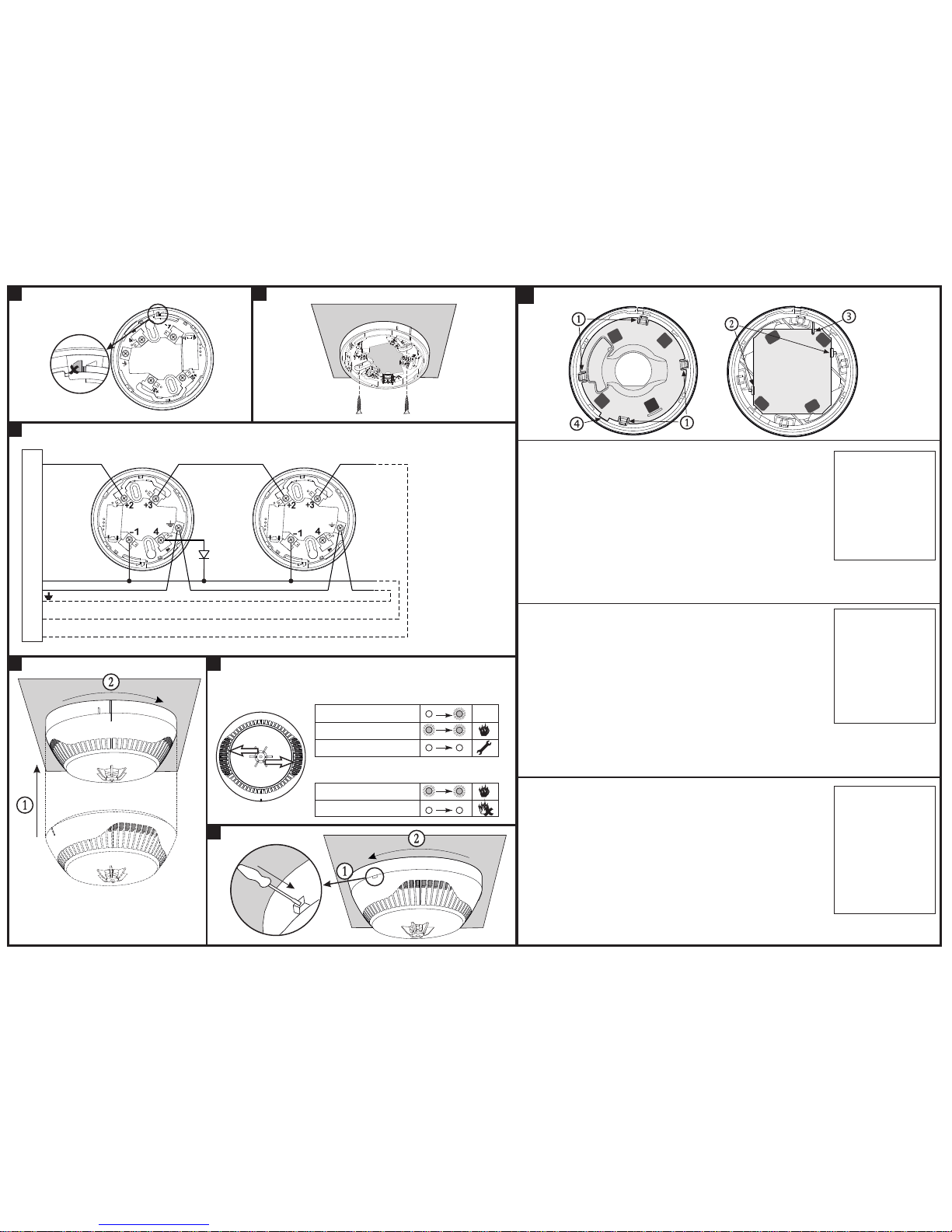
Wiring Diagram / Esquema de conexión / Схема на свързване
RI - Remote Indicator/
Indicador exterior/
Надвратен индикатор
+Loop - Positive loop wire/
Bucle positivo
Положителен извод
-Loop - Negative loop wire/
Bucle negativo
Отрицателен извод
Earth - Earth point/
Bucle de toma de tierra/
Заземителен извод
5
LED Indication / Indicación luminosa /
Светлинна Индикация
Blinking/ Parpadea/ Мига
10 sec
OK
Light on/ Se ilumina/ Свети
Light off/ No se ilumina/ Не свети
Light on/ Se ilumina/ Свети
Light off/ No se ilumina/ Не свети
1. Blinking is enabled/ Parpadeo activado/
Разрешено мигане
2. Blinking is disabled/ Parpadeo desactivado/
Забранено мигане
!
Maintenance / Mantenimiento / Поддръжка
4
Test
1. Apply power to the detector.
2. Wait for 30 sec.
3. Exert influence on the fire detector by smoke generator (Aerosol Dispenser) or by aerosol simulator
of smoke to test the optical part; or use heat tester (Cordless Heat Detector Tester or Heat Tester
110V>240V) at distance of 20 cm to test the heat part. Within 8 sec the fire detector will enter in fire
condition. Both LEDs will light up.
4. Power off the detector for 2 sec minimum. After resetting the detector will enter in duty mode and
the LEDs will light off.
Cleaning and Maintenance
1. Remove the detector from its base.
2. Remove the inner protective cover - press the four clips (1) with a plain screw-driver gently down to
unlock the cover from the detector’s body.
3. Dismount the PCB from the supporting clips (2).
4. Clean the heat chamber.
5. Mount the PCB back to the detector’s body - as a reference point use the side with a cut-out (3).
Rotate the PCB until the cut-out coincides with the pin on the inner part from the detector body. Gently
press the PCB down to fix in place.
6. Mount the inner protective cover - the mark with a rectangular shape (4) fits with the channel at the
inner side of the detector’s body and the contact plates on the PCB coincide with the four openings on
the protective cover. Press gently down until a click is heard.
7. Mount the detector back to its base and test for correct operation and LED indication.
Тест
1. Подайте захранващо напрежение на детектора.
2. Изчакайте 30 сек.
3. Въздействайте с генератор на дим (Aerosol Dispenser) или с друго аерозолно устройство, за
да тествате оптичната част; или използвайте топлинен тестер (Cordless Heat Detector Tester или
Heat Tester 110V>240V) върху детектора от разстояние 20см. В границите на 8 секунди след
въздействието детектора трябва да се установи в състояние “ПОЖАР”. Двата светодиода ще
светнат едновременно.
4. Прекъснете за 2 сек. минимум захранването на детектора. След подобен ресет детектора ще
се установи в дежурен режим и двата светодиода ще изгаснат.
Почистване и Поддръжка
1. Свалете детектора от основата.
2. Свалете вътрешния защитен капак - с подходяща отвертка натиснете леко в щипките (1), за
да ги отключите от корпуса на детектора.
3. Извадете платката от придържащите щипки (2).
4. Почистете камерата на детектора.
5. Монтирайте платката обратно към корпуса - използвайте за ориентир страната с прорез
навътре (3). Завъртете платката така, че прореза да съвпадне с репера от вътрешната страна
на корпуса на детектора. Натиснете внимателно платката надолу, за да я фиксирате на място.
6. Монтирайте вътрешния защитен капак - реперът с правоъгълна форма (4) трябва да
съвпадне с жлеба от вътрешната страна на корпуса, а конктните пластини на платката - с
четирите отвора на защитния капак. Натиснете леко надолу докато се чуе щракване.
7. Монтирайте детектора обратно към основата и тествайте за работоспособност и индикация.
The service
maintenance of the
detector should be
provided:
1. Inspection for visible
physical damage - weekly.
2. Operational test in real
conditions - monthly.
3. Check and clean dust
contamination - six months.
4. Check and clean base and
head contacts and
connections - annually.
Сервизна поддръжка
на детекторите трябва
да се извършва:
1. Външен оглед за видими
механични повреди ежеседмично
2. Проверка на
работоспособността в
реални условияежемесечно
3. Профилактично
почистване на замърсяване
от прах- 6 месеца
4. Профилактична проверка
и почистване на контактната
система - 1 година.
El mantenimiento de los
detectores deberá
efectuarse:
1. Examen exterior por daños
mecánicos visibles: cada
semana.
2. Inspección de la capacidad
de funcionamiento en
condiciones reales: cada mes.
3. Limpieza preventiva por
impurezas de polvo: cada 6
meses.
4. Inspección preventiva y
limpieza del sistema de
contacto: 1 vez al año.
Prueba
1. Suministre voltaje de alimentación al detector.
2. Espere durante 30 segundos.
3. Ejerza influencia con un generador de humo (Aerosol Dispenser) o con otro dispositivo de aerosol
para probar la parte óptica; o bien utilice un ensayador térmico (Cordless Heat Detector Tester o Heat
Tester 110V>240V) sobre el detector desde una distancia de 20 cm. En los límites de 8 segundos
después de haber ejercido la influencia sobre el detector, deberá establecerse en estado de
“INCENDIO”. Ambos diodos LED se iluminarán simultáneamente.
4. Interrumpa mínimo durante 2 segundos la alimentación del detector. Después de un tal rearme, el
detector pasará a modo de reposo y ambos diodos LED se apagarán.
Limpieza y Mantenimiento
1. Retire el detector de la base.
2. Retire la tapa interna de protección: con un destornillador apropiado, presione ligeramente en las
pinzas (1) del cuerpo del detector para abrirlas.
3. Saque el circuito de las pinzas de soporte (2).
4. Limpie la cámara del detector.
5. Instale de nuevo el circuito en el cuerpo: utilice, a modo de orientación, la parte con una ranura (3)
hacia adentro. Haga girar el circuito, de modo que la ranura coincida con el punto de referencia de la
parte interna del cuerpo del detector. Presione cuidadosamente el circuito hacia abajo para fijarlo en el
lugar.
6. Instale la tapa de protección interna: el punto de referencia de forma rectangular (4) deberá coincidir
con el canal por la parte interna del cuerpo, y, las placas de contacto del circuito, con las cuatro
aberturas de la tapa de protección. Presione ligeramente hacia abajo, hasta que se oiga un chasquido.
7. Instale nuevamente el detector en la base, y ensaye la capacidad de funcionamiento y la indicación.
Fire Panel / Panel de alarma de incendio /
Пожароизвестителен панел
Earth
RI
+Loop
-Loop
-Loop
+Loop
B124 B124
2
1
Base B124 / Основа B124
6
 Loading...