

Page 1
LCD 63SE (VG)
Operation User Manual
LCD 63SE Keyboard
LCD 63VG SE Keyboard with voice guiding
C
English
Page 2
2
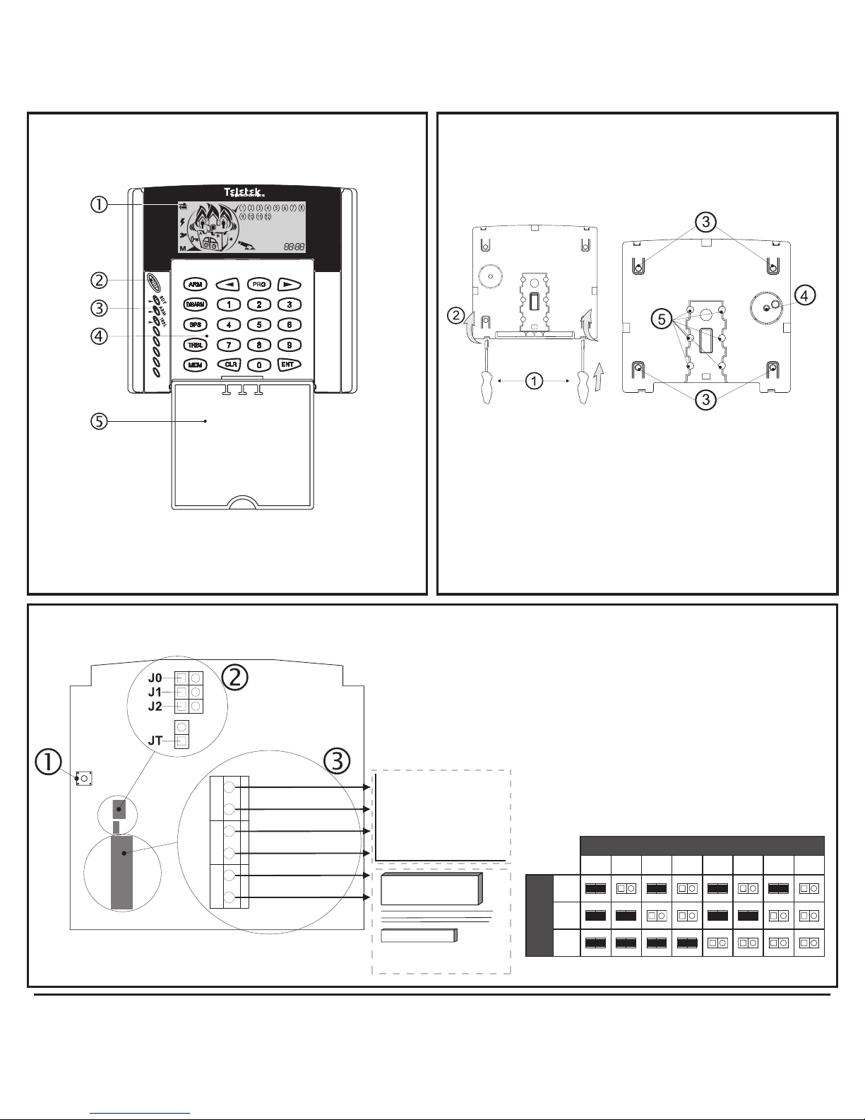
Frontal view
LCD 63SE (VG)
- LCD display; - Speaker opening
- LED indication; - Keypad
- Protective cover (open)
Mounting
LCD 63SE (VG)
, - Back cover opening
- Mounting holes; - Back tamper*
- Wire openings;
* To ensure an anti-vandalism protection it is
necessary to fix with a screw the back tamper
to the mounting surface!
Connection
Zone 1
Door
Contact
Green
Yellow
Red
Black
CA62
GND
Zone
Green
Yellow
Red
Black
LCD 63SE (VG)
Address Table
Keypad Address
1 2 3 4 5 6 7 8
Jumpers
J0
J1
J2
- Tamper switch
- Jumpers for address programming:
J0, J1, J2 - for keypad address - see the address table
JT Jumper - set only in the last device
- Terminals for wire zone connection
Page 3

3
CONTENTS
GENERAL INFORMATION ..........4
LCD 63SE (VG) DESCRIPTION
LED Indication ....................5
Keypad Sounder...................5
Voice Messages (LCD 63VG SE)......5
Display ..........................6
Buttons ..........................8
LCD 63SE (VG) OPERATION
Arming of Partition A ..............9
“Full ARM” Mode . . . . . . . . . . . . . . . . . . 9
“Stay ARM” Mode. .................10
“Instant ARM” Mode . . . . . . . . . . . . . . . . 11
Arming of Partition B ..............11
Arming Both Partitions A and B .....12
Voice messages in arming mode ....12
Disarming Partitions A, B, and both..12
Voice messages in disarming .......13
Stopping the Alarm ...............13
Panic Buttons ....................13
Ambush Code ....................13
Technical Troubles Review .........14
User Level Programming
Changing own user code ............14
Memory LOG Review from User ......15
Chime Enable/Disable from User ......15
Zone Bypassing from user . . . . . . . . . . . 15
Manager Level Programming
Changing User Rights for Remote access 16
Enable/Disable Engineer Code access .17
Sending of “Comm. test” message.....17
UDL Access Block .................17
Changing User Codes ..............18
Changing User Rights ..............18
Changing Manager Codes . . . . . . . . . . . 18
Changing Manager Rights ...........19
Memory LOG Review from Manager ...19
Chime Enable/Disable from Manager...19
Zone Bypassing from Manager .......20
Setting the Clock ..................20
Setting the Date ...................20
Adding a Proximity Card.............20
Deleting a Proximity Card............20
System Information ...............21
APPENDIX: Table of the events.......22
Page 4

4 LCD 63SE (VG) Keypad User Manual
General Information
Limited Warranty
The manufacturer warrants that for period of 12 months from the date of purchase, the product shall be free
of defects in material and workmanship under normal use and that in fullment of any breach of such warranty, The manufacturer shall, at its opinion, repair or replace the defective equipment upon return of the
equipment to its factory. This warranty applies only to defects in parts and workmanship and not to damage
incurred in shipping or handling, or damage due to causes beyond the control of The manufacturer such
as lightning, excessive voltage, mechanical shock, or damage arising out of abuse, alternation or improper
application of the equipment.
The foregoing warranty shall apply only to the original buyer, and is and shall be in lieu of any and all other
warranties, whether expressed or implied and of all other obligations or liabilities on the part of The manufacturer. This warranty contains the entire warranty. The manufacturer neither assumes, nor authorizes any
other warranty or liability concerning this product.
In no event shall The manufacturer be liable for any direct or indirect or consequential damage, loss of
anticipated prots, loss of time or any other losses incurred by the buyer in connection with the purchase,
installation or operation or failure of this product.
The manufacturer recommends that the entire system be completely tested on a regular basis. However,
despite frequent testing, and due to, but not limited to, criminal tampering or electrical disruption, it is possible
for this product to fail to perform as expected.
Warnings
Before using the LCD 63SE / LCD 63VG SE Keypad, please ensure that you have read and understood the
following instructions. Always ensure that the LCD 63SE / LCD 63VG SE Keypad is operated correctly.
Do not attempt to disassemble or alter any part of the equipment that is not expressly described in this guide.
Internal inspections, alterations and repairs should be conducted by qualied service personnel only.
Do not use substances containing alcohol, benzene, thinners or other ammable substances to clean or
maintain the equipment. The use of these substances may lead to re.
Do not allow liquids to enter the interior. The equipment is not waterproof.
Disclaimer
♦ The manufacturer reserves the right to change the specications of the equipment described in this manual
without notice.
♦ This document contains information proprietary to the manufacturer. No part of this publication may be
reproduced, photocopied, stored on a retrieval system or transmitted, without prior written permission of the
manufacturer.
♦ While every effort has been made to ensure that the information in this manual is accurate and complete,
no liability can be accepted for any errors or omissions.
ATTENTION
This manual contains information on limitations regarding the product use and functions, as well as
information on the limitations as to liability of the manufacturer.
The entire manual should be carefully read!
Page 5
LCD 63SE (VG) Keypad User Manual 5
Description
The LCD 63SE and LCD 63VG SE keyboards provide complete control - programming and status
information of the CA62 control panel. A LCD display and LED indication visualize alarm and status
information. A sound buzzer informs the user about correct and incorrect key entries as well as
activated alerts.
LCD 63VG SE provides 7 voice messages for guiding the user for the system status: arming or
disarming, alarm in the system, etc.
NOTE: This manual concerns the operation with both LCD 63SE and LCD 63VG SE keyboard
models. For the sake of brevity, where the information is about the both keyboards they will
be written as LCD 63SE (VG).
LED Indication
LED Light Blinking
RDY (green) System ready Programming mode
ARM (red) System armed Exit time / Programming mode
TRBL (yellow) - Technical problem / Programming mode
Keypad Sounder
There are 7 different sound combinations that indicate seven different conditions:
♦ Click - single short beep indicating button pressing.
♦ Conrmation - two long beeps, indicating the system conrmation to executed operation (arming,
disarming, settings change, etc.).
♦ Reject - single long beep, indicating incorrectly executed operation.
♦ Entrance time - continuous beep, indicating intrusion into the entrance zones.
♦ Exit time - short beeps, indicating the system is armed and the user is required to leave the area.
10 seconds before the exit time is over, beeps frequency is increased.
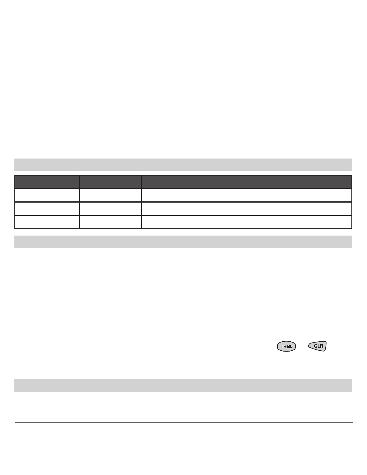
♦ Technical trouble - two short beeps at every 20 sec, indicating a technical trouble (battery low, no
supply voltage, etc.). To stop the signalization press sequentially the buttons
→ .
♦ Chime - short beeps with subsequently increasing period indicating intrusion into a zone with a
“Chime“ option activated.
Voice Messages (LCD 63VG SE)
There are seven different voice messages that indicate different system statuses:
1. “System is armed”; 2. “System is disarmed”; 3. “Please, enter your code to disarm”; 4. “AC power
is lost”; 5. “Battery is discharged”; 6. “Please, leave the premises”; 7. “Alarm in the system”.
Page 6
6 LCD 63SE (VG) Keypad User Manual
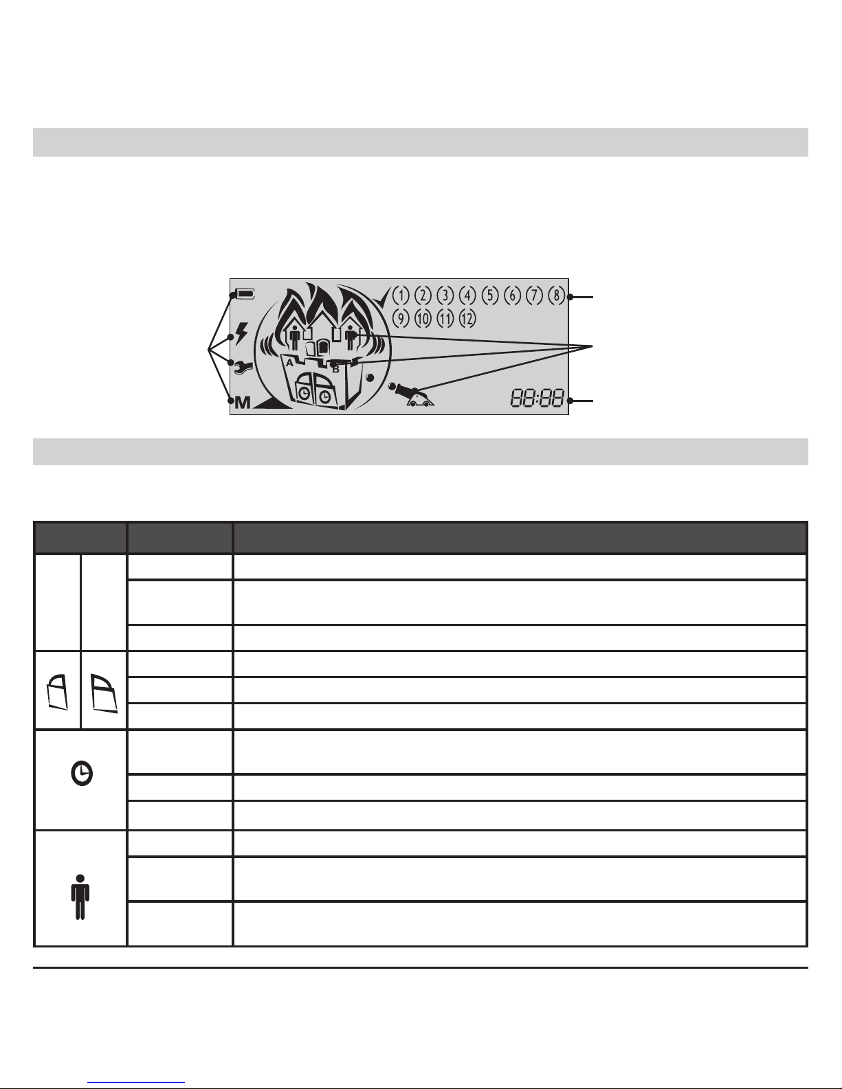
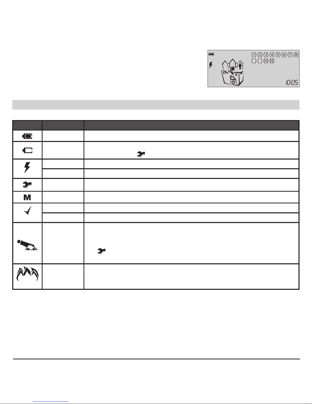
Display
An icon LCD display provides information for the status of the Partitions (A and B) in the system, and
also the type of ARMING mode - “Full ARM” (see page 9), “Stay ARM” (see page 10) and “Instant
ARM” (see page 11). The LCD 63SE (VG) keyboards are equipped with blue backlight of the buttons and LCD display. The backlight is activated easily with pressing a random button, opening of
“Entry-Exit” or “Follow” type zones.
Icons for
status of the
control panel
Icons for
Partition status,
ARM mode and
events
Zones status
Clock; addresses
Icons for Partitions Status and ARMING mode
The animated icons for A and B partitions are situated in a house divided into two partitions. According the current status of the system the icons have the following performance:
Icon Indication Description
A B
OFF Partition A / Partition B is not ready for ARMING.
ON
Partition A / Partition B is ready for ARMING; or the partition is ARMED,
regardless of the ARMING mode.
Blinking “Alarm”, “Fire” or “Memory” event in the respective partition.
OFF The respective partition is DISARMED.
ON
The respective partition is ARMED.
Blinking Entry-exit time is running.
OFF
The respective partition is DISARMED; or the partition is ARMED in “Instant ARM” mode.
ON The respective partition is ARMED in “Full ARM” or “Stay ARM” mode.
Blinking Entry-exit time is running.
OFF There are no bypassed zones in the system.
ON
There are bypassed zones in ARMED system. The numbers of the by-
passed zones are missing - only the brackets are visible.
Blinking
There are bypassed zones in DISARMED system. The numbers of the
bypassed zones are missing - only the brackets are visible.
Page 7
LCD 63SE (VG) Keypad User Manual 7
Example:
The Partition A is ready to be armed - the icon “A” lights on. The
Partition B is in “Stay ARM” mode - the icons “clock”, “door”
and “man” light on. Zones 9 and 10 are bypassed - only the
brackets are visible.
Icons for Status of the control panel
The status of the control panel is visualized with the following icons:
Icon Indication Description
ON The battery of the control panel works properly.
Blinking
The Battery of the control panel is at low charge or is missing; blinks
together with the
icon.
ON Power supply 220 VAC.
Blinking Power supply 220 VAC lost.
Blinking Technical trouble in the system - see page 14.
ON Memory events LOG - see page 15, 19.
ON The system is ready to be armed.
Blinking Programming mode.
Animation -
gun ring
BURGLAR alarm event in the system - the gun is ring towards the
house.
TAMPER alarm in the system - the gun is ring towards the house and
the icon is blinking.
The icon (A or B) of the partition in burglar / tamper alarm is blinking.
Animation -
ames over
the house
FIRE alarm event in the system - the ames are blinking over the
house.
The icon (A or B) of the partition in re alarm is blinking.
Page 8
8 LCD 63SE (VG) Keypad User Manual
Icons for Zone Status, clock and visualizing the addresses
The zone status is visualized with the following icons:
Zones Indication* Description
1, 2,
...
12
1 Number only No activated detectors in the system; the zone is closed.
(1)
Number with
blinking brackets
Activated detectors in the system; the brackets around the
opened zones are blinking.
Number in
brackets (1 - 6)
Technical trouble. The icon (A or B) of the partition with trouble
is blinking.
( ) Brackets only
The zone is bypassed. The icon “man” blinks slowly when the partition is DISARMED and lights on when the partition is ARMED.
* Refers to all zones in the system - from 1 to 12.
- displays various information (time, date, codes, etc.)
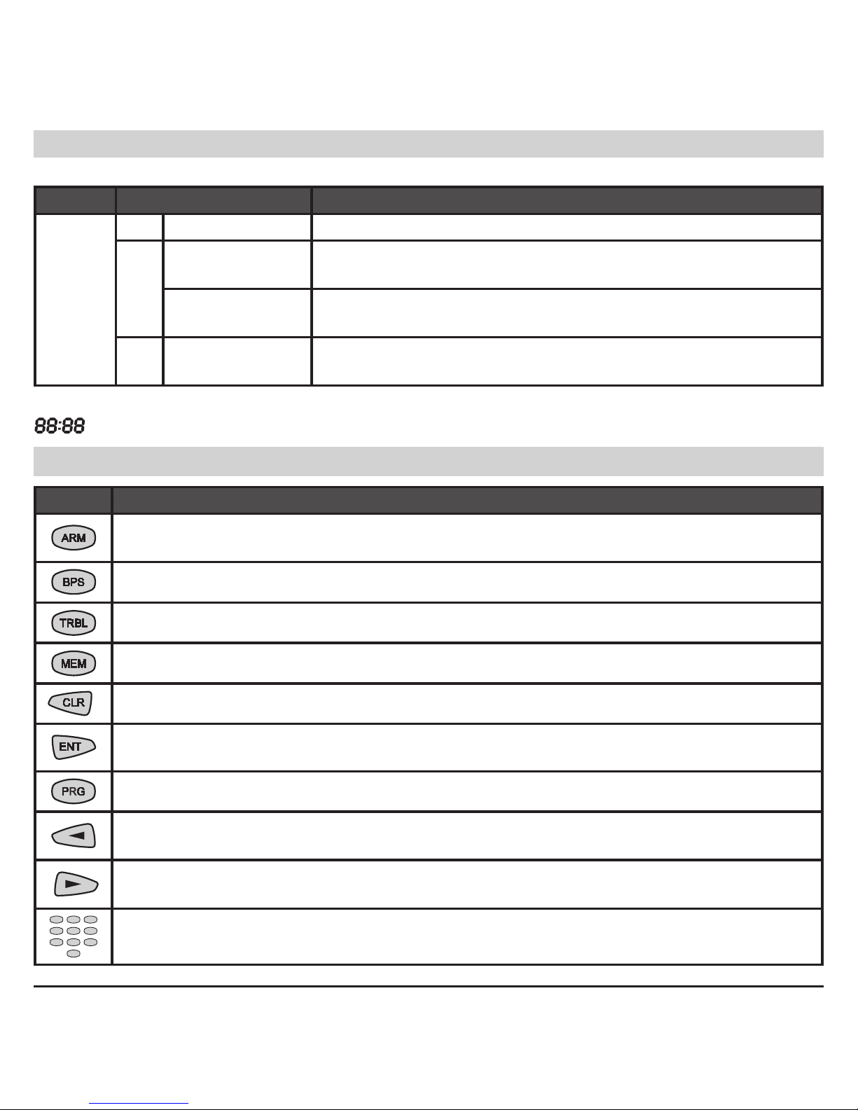
Buttons
Button Function
ARMING of Partition A, Partition B or both of them - this functionality of the button is
programmed from the installer.
Bypasses certain zone(s).
Reviews the system troubles.
Reviews the memory events LOG.
Clears entered data or transfers to previous menu level.
Conrms entered data or transfers to next menu level.
Entering the Manager or User programming menus.
Scroll the LOG memory or the system troubles review to the previous event. ARMING or DISARMING of Partition A - this functionality of the button is programmed from the installer.
Scroll the LOG memory or the system troubles review to the next event. ARMING or DISARMING of Partition B - this functionality of the button is programmed from the installer.
Used to enter different digital data, for example personal user or manager access
codes, settings, menu addresses, etc.
Page 9

LCD 63SE (VG) Keypad User Manual 9
LCD 63SE (VG) Keypad Operation
Arming of Partition A
The system can be ARMED when the icon is displayed on the LCD and the icon for Partition A
is ON.
NOTE: The ARMING sequence depends on the programmed parameters in the Engineers
menu! Ask your installer which of the described below ARMING variants you have to use!
“Full ARM” Mode for Partition A
Full arming means all zones are secured. Anyone coming into the entrance zone is required to enter
a valid code*. Otherwise an alarm will be generated after the entrance time is over.
ARMING VARIANT 1 for “Full ARMING” of Partition A (with choosing the type of the ARMING
Mode - default setting):
ARMING VARIANT 2 for “Full ARMING” of Partition A (without choosing the type of the ARMING
Mode - programmed from the installer):
ARMING VARIANT 3 for “Full ARMING” of Partition A (quick ARMING without user code, but with
choosing the ARMING Mode type - default setting):
ARMING VARIANT 4 for “Full ARMING” of Partition A (quick ARMING without user code and
ARMING Mode type - programmed from the installer):
At the end of the “Full ARM” procedure, regardless of the used
arming variant, the icons of “Partition A”, “door” and “clock” are
ON.
* To the user code are assigned rights to operate with Partition A, otherwise the system will reject
the operation.
code*
exit
time
code
*
exit
time
exit
time
exit
time
Page 10

10 LCD 63SE (VG) Keypad User Manual
“Stay ARM” Mode for Partition A
Stay arming means the user is allowed to stay in certain bypassed zone(s) after arming the system,
but the entrance zone is secured. Anyone coming into the entrance zone is required to enter a valid
code*. Otherwise an alarm will be generated after the entrance time is over.
The zone bypassing is described on pages 15 and 16 (user), and 19 (manager).
Note: Certain users may not be permitted to arm the system in “Stay ARM” mode.
ARMING VARIANT 1 for “Stay ARMING” of Partition A (with choosing the type of the ARMING
Mode - default setting):
ARMING VARIANT 2 for “Stay ARMING” of Partition A (without choosing the type of the ARMING
Mode - programmed from the installer):
ARMING VARIANT 3 for “Stay ARMING” of Partition A (quick ARMING without user code, but
with choosing the ARMING Mode type - default setting):
ARMING VARIANT 4 for “Stay ARMING” of Partition A (quick ARMING without user code and
ARMING Mode type - programmed from the installer):
At the end of the “Stay ARM” procedure, regardless of the used
arming variant, the icons of “Partition A”, “door” and “clock” are
ON. The icon “man” is ON in the Partition A. The number(s) of
the bypassed zone(s) are missing, only the brackets around them
are visible.
* To the user code are assigned rights to operate with Partition A, otherwise the system will reject
the operation.
exit
time
exit
time
exit
time
exit
time
code
*
code*
Page 11

LCD 63SE (VG) Keypad User Manual 11
“Instant ARM” Mode for Partition A
Instant arming means the user is allowed to stay in certain zone(s) after arming the system, but the
entrance zone is secured. The difference with the stay arming is that intrusion into the entrance zone
immediately generates an alarm.
ARMING VARIANT 1 for “Instant ARMING” of Partition A (with choosing the type of the ARMING
Mode - default setting):
ARMING VARIANT 2 for “Instant ARMING” of Partition A (without choosing the type of the ARM-
ING Mode - programmed from the installer):
ARMING VARIANT 3 for “Instant ARMING” of Partition A (quick ARMING without user code, but
with choosing the ARMING Mode type - default setting):
ARMING VARIANT 4 for “Instant ARMING” of Partition A (quick ARMING without user code and
ARMING Mode type - programmed from the installer):
At the end of the “Instant ARM” procedure, regardless of the used
arming variant, the icons of “Partition A” and “door” are ON. The
icon “man” is ON in the Partition A. The number(s) of the bypassed
zone(s) are missing, only the brackets around them are visible.
* To the user code are assigned rights to operate with Partition A, otherwise the system will reject
the operation.
Arming of Partition B
ARMING of the Partition В in the system is done in the same way, as shown above for the Partition
A, but the user presses the button. The user must have a valid code for Partition B!
When the system is used to protect two independent sites, it is possible also to arm Partition A in one
ARMING Mode and Partition B in another ARMING Mode.
code*
code*
Page 12
12 LCD 63SE (VG) Keypad User Manual
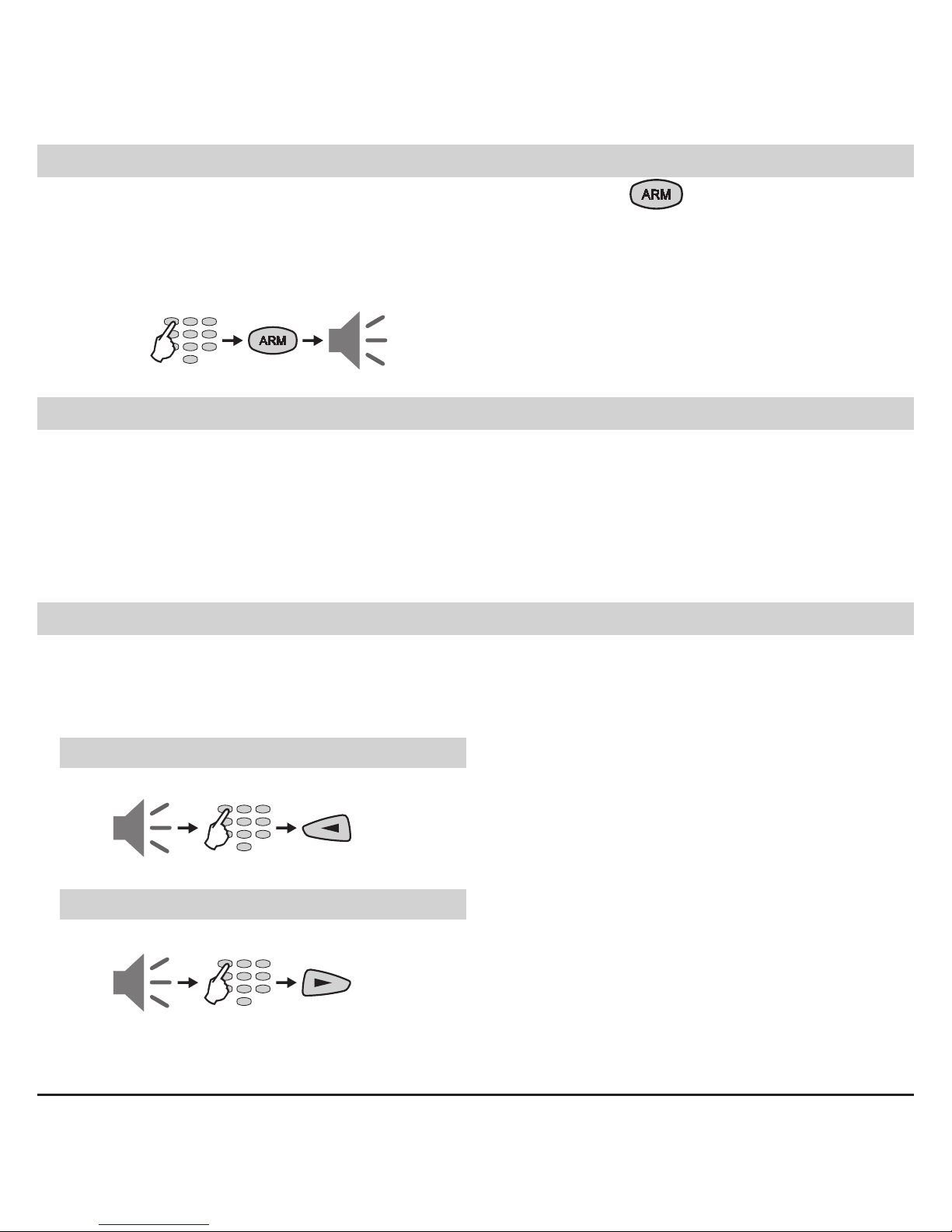
Arming Both Partitions A and B
For ARMING both Partitions A and B together, the user can use the button, when this function
is programmed from the Installer.
Note: With the ARM Button the user can arm the system only in “Full ARM” Mode. The user must
have a valid code with rights to operate in both Partition A and B!
ARMING Both Partitions A and B in “Full ARM” Mode (programmed from the installer):
Voice Messages in Arming Mode (LCD 63VG SE)
With all arming modes, except Instant, after exit time starts running, the “Please leave the premises”
voice message will sound every 5 seconds. The buzzer will indicate that exit time is running. Ten
seconds before exit time is over, beep frequency will increase.
After arming, the “System is armed” message will be repeated twice.
In the events of AC loss and low battery, the “AC power is lost” or “Battery discharged” messages
will sound correspondingly 3 times every 5 seconds when arming is attempted.
Disarming of Partition A, Partition B or Both Partitions
Going into the entrance zone the user must introduce his personal code. A continuous sound signal
indicates intrusion in the entry zone and entry time starts running.
Note: Certain users may not be permitted to disarm the system.
Disarming of Partition A
Disarming of Partition B
exit
time
code
entry
time
entry
time
code
code
Note: To the user code are assigned rights to operate with
Partition A, otherwise the system will reject the operation!
Note: To the user code are assigned rights to operate with
Partition B, otherwise the system will reject the operation!
Page 13

LCD 63SE (VG) Keypad User Manual 13
Disarming Both Partitions A and B
Voice Messages in Disarming Mode (LCD 63VG SE)
A continuous beep indicates the entrance time. The voice messages “System is armed” and “Please,
enter your code to disarm” will sound on every 5 seconds.
After a valid code has been entered, the message “System is disarmed” will be repeated twice.
If no valid code has been entered during entry time, the “System is armed” message will sound.
If an alarm has been triggered in the system, the messages “Alarm in the system” and “Please, enter
your code to disarm” will be repeated every 5 seconds.
Stopping the alarm
The alarm is stopped by entering a valid personal code with assigned rights to operate with both
Partitions in the system.
ATTENTION: If you cannot stop the alarm using a valid user with assigned rights to operate
with both Partitions, call the Engineer and your system technical support!
Panic Buttons
Press and hold the + buttons for 2 seconds, to send an alarm signal to the control panel.
The option not sounding the siren when using the panic buttons is programmed from the engineer.
Ambush Code
Ambush code is a personal code that disarms the system, but still sends alarm signal to a Central
monitoring station. Its purpose is to indicate that the user is forced to disarm the system against his
will.
The ambush code is produced from a personal code by increasing the last number by one. If the last
number is 9, it is replaced by 0 in the ambush code.
Example: Personal code: 4615 → Ambush code: 4616
Personal code: 4619 → Ambush code: 4610
entry
time
code
Note: To the user code are assigned rights to operate with
both Partitions A and B, otherwise the system will DISARM
only that Partition for which the User code are assigned
rights!
Page 14
14 LCD 63SE (VG) Keypad User Manual
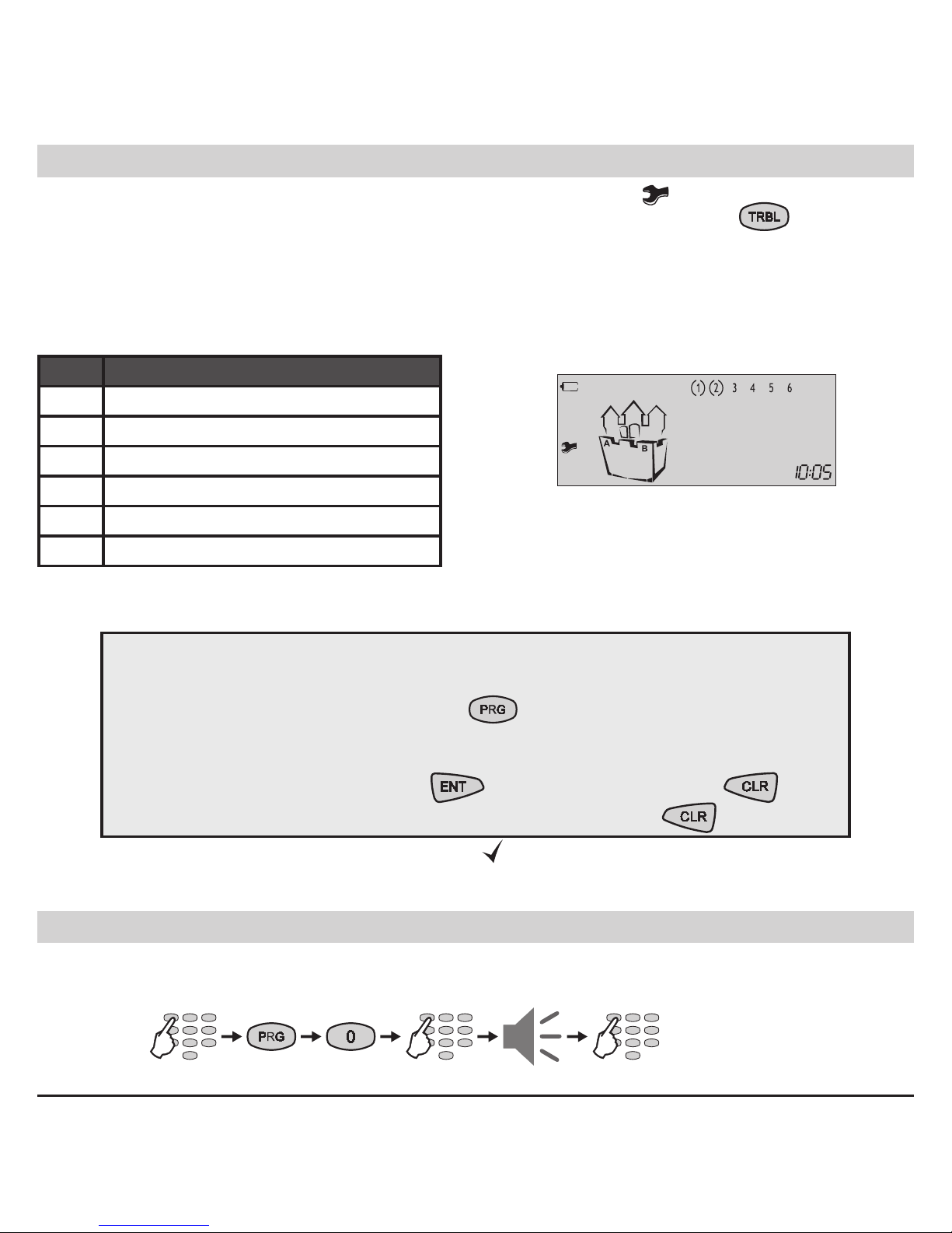
Technical Trouble Review
The technical troubles in the system are indicated with blinking icon .
To review the technical troubles in a system the user has just to press the
button. Each
number in the LCD upper right corner correspond to a certain system trouble. The “( )” icon surrounding a number indicates the respective trouble occurrence. The system will automatically exit
the technical trouble review mode after 30 seconds. The technical trouble sound signalization will
stop, but the icon “wrench” will proceed blinking until the technical trouble is eliminated.
Every surrounded in brackets digit on the display indicates one technical trouble:
LCD Technical trouble
(1) No 220 V power supply
(2) Battery charge level is low
(3) Fuse blown
(4) No telephone line
(5) No communication available
(6) Active TAMPER within the system
User’s Programming Menu
General rules for programming parameters in the User’s Menu
Step 1: Enter a valid user code → 4 or 6 digits
Step 2: Single press the PRG button →
Step 3: Enter an address number → (1 digit)
Step 4: Change the parameter value
Step 5: Conrm the change with →
button / or reject it with → button
Exit from the User Programming Menu → press several times
button
The blinking LEDs “Ready”, “ARM”, “TRBL” and “
” icon show that the system is in programming
mode. Note: Certain users may not be permitted to program the system.
Changing Own User Code
The user is required to enter his current personal code before changing it.
Sequence of operations for changing user code:
Example: Two technical troubles in the
system - No power supply of the control
panel and low battery charge.
4 or 6 digits
new code
repeat
code
new code
Page 15

LCD 63SE (VG) Keypad User Manual 15
Memory LOG Review from User
To review the memory LOG le the user has to enter a valid code:
To view the code, the time and the date of the event use the following buttons:
Example: There has been an alarm event in the 4th zone at 21:08h - this is the rst information
displayed on the LCD screen. Press the button to see the day and month of happening of the
event - December, 10th. Press the button - the rst two digits are the event code number (check
it in the Appendix: Table of events on page 22), the next two digits (blinking) are showing the zone/
user number respectively.
Chime Enabling / Disabling from User
To turn the chime mode on or off the user is required a personal code. Pressing any numeric key
switches alternatively the chime mode on and off. Pressing conrms the selection.
By default the chime is disabled.
Turning the chime ON and OFF key sequence:
Zone Bypassing by User
To execute bypass operation the user is required a personal code. Pressing a numeric key bypasses
the respective zone. The zone number is surrounded by the “(-)” icon. Pressing the same key once
again restores the zone bypass. The “(-)” icon is removed. Pressing conrms the selection.
Bypassing key sequence (zone 2 in the example):
- previous event,
- following event
code
code
the chime is
disabled
the chime is
enabled
conrm
code
zone 2 is not
bypassed
zone 2 is bypassed
conrm
Page 16
16 LCD 63SE (VG) Keypad User Manual
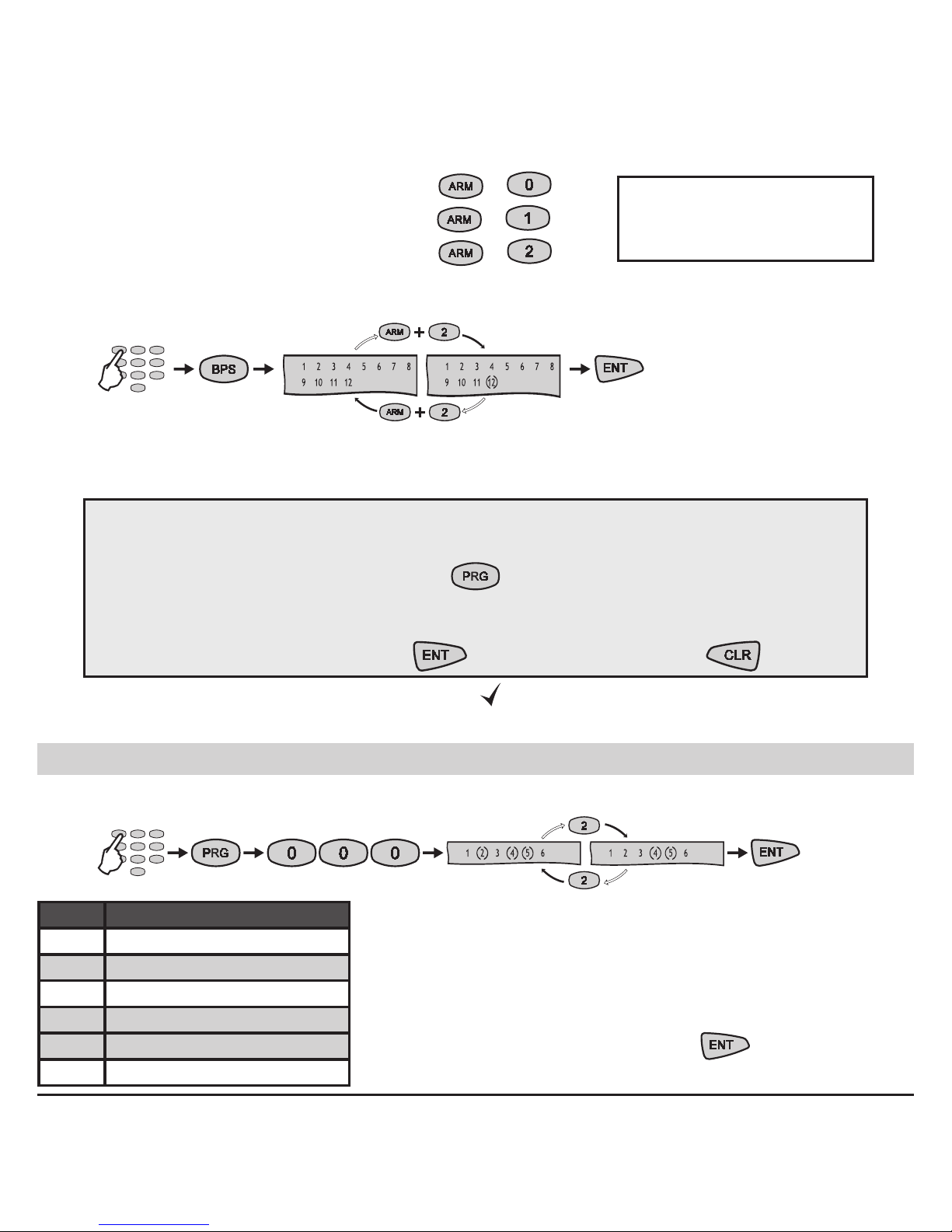
ATTENTION! To bypass zones 10, 11 and 12 you have to use special button combinations:
• To bypass Zone 10 use button combination
+ .
• To bypass Zone 11 use button combination
+ .
• To bypass Zone 12 use button combination
+ .
Bypassing zone button sequence (zone 12 in the example):
Manager’s Programming Menu
General rules for programming parameters in the Manager’s Menu
Step 1: Enter a valid user code → 4 or 6 digits
Step 2: Single press the PRG button →
Step 3: Enter an address number → (3 digits)
Step 4: Change the parameter value
Step 5: Conrm the change with →
button / or reject it with → button
The blinking LEDs “Ready”, “ARM”, “TRBL” and “
” icon show that the system is in programming
mode.
Changing User Rights for Remote Access
To change the user rights for remote access, the manager is required to enter his personal code.
Note: Certain users may
not be permitted to bypass
zones in the system.
code
zone 12 is not
bypassed
zone 12 is bypassed
conrm
The display indicates the respective operations the user is
allowed to execute. The numbers in brackets indicate the
permitted operations. Pressing a numeric button alternatively switches over the state of the respective remote access right from disabled to enabled. The selected programming is conrmed by pressing the button.
* Default settings.
default settings
LCD Remote access rights
1 Remote DISARM
(2) Remote ARM*
3 Remote Code Access
(4) Remote Programming*
(5) Remote LOG Review*
6 Remote Bypass
conrm
disabling the Remote ARM
code
Page 17

LCD 63SE (VG) Keypad User Manual 17
Enabling / Disabling the Engineer Code Access
To enable / disable the Engineer code right to access the Engineer programming menu, the Man-
ager is required to enter a valid code rst:
Pressing any numeric button alternatively changes the state of the parameter from enabled to disabled and vice versa. The selected state is conrmed by pressing the button.
By default the Engineer is allowed to enter the Engineer Menu.
Sending of “Comm. Manual test” Message
At this address the Manager can send a “Communication Manual Test” message to a central moni-
toring station or test message with the voice dialer VD60 (just in case there is integrated voice dialer
VD60 to the CA62 control panel). The application of this function is to test the communication part in
the system from the manager, without need of sending the Engineer to the site.
To send a “Comm. Test” message, the manager is required to enter his code:
The communicator will start transmitting test messages through the digital communicator to the
central station rst (if there are entered telephone numbers) and then through VD60 (if it is available
in the system and there are entered telephone numbers).
UDL Access Block
At this address the Manager enters a permissible number of valid access codes for UDL (ARM /
DISARM / BYPASS / PC ID) for a 24 hour period. Enter a number from 00 up to 99 (the default settings is 10 attempts).
With reaching the permissible number of valid access codes, the system will be blocked - there
would be no UDL communication. The UDL communication will be restored at 00:00h system time.
To enter a permissible number of codes, the manager is required to enter his personal code rst:
code
default setting
disables the
Engineer access
conrm
code
2 beeps
exit from
the menu
code
2 beeps digit 00-99
Page 18

18 LCD 63SE (VG) Keypad User Manual
Changing of User Codes
To change any user code the Manager is required to enter his personal code rst.
User code change button sequence:
Numbers (3), (4), (5) and (6) are ON to indicate the number of code digits left to be entered.
Note: If 6-digit codes are used in the system, then numbers (1), (2), (3), (4), (5) and (6) are ON.
If the new code is repeated correctly the system will conrm it with a sound signal.
Changing of User Rights
To change the User rights the Manager is required to enter his personal code rst.
User rights change button sequence:
The display indicates the respective operations the user is allowed to execute. The numbers in
brackets indicate the permitted operations.
Changing of Manager Codes
LCD User’s rights
(1) DISARM*
(2) Stay ARM*
(3) Bypass*
(4) Programming*
(5) Working with Partition A*
6 Working with Partition B
Pressing a numeric button alternatively switches over the state
of the respective user’s right from disabled to enabled. The selected programming is conrmed by pressing the
button.
Note: Disabling all user rights will automatically erase the
programmed code combination!
* Default settings for User’s rights.
Addresses for Manager codes:
- Changing the Chief Manager code
- Changing the Manager code No1
- Changing the Manager code No2
- Changing the Manager code No3
Up to 4 different manager codes can be pro-
grammed in the СА62 control panel, i.e. there
can be up to 4 Managers in the system - 1 Chief
Manager and 3 sub-managers. Changing of
the different Manager codes can be done at different addresses in the system.
code
2 beeps 2 beepsuser
No 01 - 20
new codenew code
4 or 6
digits
repeat
code
user
No 01 - 20
default settings
disabling user
programming
Page 19

LCD 63SE (VG) Keypad User Manual 19
To change his code the manager is required to enter his current manager code before changing it.
Numbers in brackets (3), (4), (5) and (6) are ON to indicate the number of code digits left to be
entered.
Note: If 6-digit codes are used in the system, then numbers (1), (2), (3), (4), (5) and (6) are ON. If the
new code is repeated correctly the system will conrm it with a sound signal and will exit automatically from the Manager programming menu.
Changing of Manager Rights
To change his rights the manager is required to enter his current manager code.
Pressing a numeric button alternatively switches over the state of the respective manager’s right
from disabled to enabled. The display indicates the respective operations the manager is allowed to
execute. The numbers in brackets indicate the permitted operations.
The selected programming is conrmed by pressing the
button.
* Default settings for Chief Manager in the system. For sub-managers No 1, 2 and 3 there are no
programmed rights by default. NOTE: Disabling all manager rights will automatically erase the
programmed code combination!
Memory LOG review from Manager
To review the memory LOG of events the manager is required to enter his code.
See also the example on page 15.
Chime Enable / Disable from Manager
To enter enable/ disable chime mode, the manager is required to enter his code.
code
2 beeps 2 beepsManager
Address 2x
new codenew code
4 or 6
digits
repeat
code
Manager
Address 2x
- previous event,
- following event
code
LCD Manager rights
(5) Working with Partition A*
(6) Working with Partition B*
code
2 beeps
Page 20

20 LCD 63SE (VG) Keypad User Manual
Pressing a numeric button alternatively switches over the state of the chime from disabled to enabled. The selected programming is conrmed by pressing the
button. By default the chime is
disabled. See also the example for chime enable / disable from User - page 15.
Zone Bypassing from Manager
To execute a bypass operation the manager is required to enter a valid code:
Pressing a numeric button bypasses the respective zone. The zone number is surrounded by the
“(-)” icon. Pressing the same key once again restores the zone bypass. The “(-)” icon is removed.
Pressing conrms the selection. See also the examples for zone bypassing from User - page
15.
Setting the Clock
To set the clock the manager is required to enter his personal code.
Setting the Date
To set the date the manager is required to enter his personal code.
Adding a Proximity card
To use proximity cards the system has to be equipped with a proximity card reader.
User No 01 - 20 or
Manager Address 2x
2 beeps
Deleting a Proximity card
User No 01 - 20 or
Manager Address 2x
2 beeps
code
code
code
code
code
2 beeps
new time (HH:MM)
2 beeps new date (DD:MM)
Page 21

LCD 63SE (VG) Keypad User Manual 21
General system information
(Fill in from the installer)
Zone information
Zone
Type:
Room:
Zone
Type:
Room:
1 7
2 8
3 9
4 10
5 11
6 12
Outputs information
PGM1 PGM3
PGM2 SIREN
Times
Exit time (sec)
Entry time (sec)
Activated siren (min)
Installed by: .....................................................................................................................
Service: ............................................................................................................................
Tel., Fax: ...........................................................................................................................
NOTES: .............................................................................................................................
Page 22

22 LCD 63SE (VG) Keypad User Manual
APPENDIX - Events Table
Code Event description Zone/User Nо
01 Burglary alarm type activated Zone Number
02 Burglary alarm type deactivated Zone Number
03 Fire alarm type activated Zone Number
04 Fire alarm type deactivated Zone Number
05 Panic alarm type activated Zone Number
06 Panic alarm type deactivated Zone Number
07 Tamper alarm type activated Zone Number
08 Tamper alarm type deactivated Zone Number
09 Medical alarm type activated Zone Number
10 Medical alarm type deactivated Zone Number
11 Burglary zone type bypassed Zone Number
12 Burglary zone type restored Zone Number
13 Fire zone type bypassed Zone Number
14 Fire zone type restored Zone Number
15 Panic zone type bypassed Zone Number
16 Panic zone type restored Zone Number
17 Tamper zone type bypassed Zone Number
18 Tamper zone type restored Zone Number
19 Medical zone type bypassed Zone Number
20 Medical zone type restored Zone Number
21 Disarming by user User Number
22 Remote disarming by user User Number
23 Disarming by key-switch type zone Zone Number
24 Arming by user User Number
25 Remote arming by user User Number
26 Arming by key-switch type zone Zone Number
27 Quick arming type (one button arming) -
28 Programming menu entry -
29 Programming menu exit -
30 Ambush code entry User Number
31 Phone line error -
Page 23

LCD 63SE (VG) Keypad User Manual 23
32 Phone line recovery -
33 Communication failed -
34 Automatic test -
35 Manual test Manager Number
36 Fuse blown -
37 Fuse recovery -
38 System reset -
39 Power supply loss -
40 Power supply recovery -
41 Battery low or missing -
42 Battery recovery -
43 Activated zone with attribute “Write to log” Zone Number
44 Restored zone with attribute “Write to log” Zone Number
45 Activated zone with AUX attribute “24h Burglary” Zone Number
46 Activated zone with AUX attribute “AC LOST” Zone Number
47 Activated zone with AUX attribute “Battery Low” Zone Number
48 Activated zone with AUX attribute “GSM Link Trouble” Zone Number
49 Activated zone with AUX attribute “Gas Detector” Zone Number
50 Activated zone with AUX attribute “Refrigeration” Zone Number
51 Activated zone with AUX attribute “Loss of Heat” Zone Number
52 Activated zone with AUX attribute “Water Leakage” Zone Number
53 Activated zone with AUX attribute “Foil Break” Zone Number
54 Activated zone with AUX attribute “Low bottled gas level” Zone Number
55 Activated zone with AUX attribute “High temperature” Zone Number
56 Activated zone with AUX attribute “Low temperature” Zone Number
57 Restored zone with AUX attribute “24h Burglary” Zone Number
58 Restored zone with AUX attribute “AC LOST” Zone Number
59 Restored zone with AUX attribute “Battery Low” Zone Number
60 Restored zone with AUX attribute “GSM Link Trouble” Zone Number
61 Restored zone with AUX attribute “Gas Detector” Zone Number
62 Restored zone with AUX attribute “Refrigeration” Zone Number
63 Restored zone with AUX attribute “Loss of Heat” Zone Number
Page 24

18020595 Rev.A 05/2009
www.teletek-electronics.com
Address: 14A Srebarna Str., 1407 Soa, Bulgaria
tel.: (+359 2) 9694 800, fax: (+359 2) 962 52 13
e-mail: info@teletek-electronics.bg
 Loading...