

Page 1
ANALOGUE ADDRESABLE
FIRE PANEL
INSTALLATION MANUAL
VERSION 1.0
Page 2

2 Fire Panel IRIS - Installation Manual
Guarantee
During the guarantee period the manufacturer shall, at its sole discretion, replace or repair any defective product when
it is returned to the factory. All parts replaced and/or repaired shall be covered for the remainder of the original guarantee, or for ninety (90) days, whichever period is longer. The original purchaser shall immediately send manufacturer a
written notice of the defective parts or workmanship, which written notice must in all cases be received prior to expiry
of the guarantee.
International Guarantee
Foreign customers shall enjoy the same guarantee rights as those enjoyed by any customer in Bulgaria, except that
manufacturer shall not be liable for any related customs duties, taxes or VAT, which may be payable.
Guarantee Procedure
This guarantee will be granted when the appliance in question is returned. The manufacturer shall accept no product
whatsoever, of which no prior notice has been received.
Conditions for waiving the guarantee
This guarantee shall apply to defects in products resulting only from improper materials or workmanship, related to its
normal use. It shall not cover:
§ Damages resulting from transportation and handling;
§ Damages caused by natural calamities, such as fire, floods, storms, earthquakes or lightning;
§ Damages caused by incorrect voltage, accidental breakage or water; beyond the control of the manufacturer;
§ Damages caused by unauthorized system incorporation, changes, modifications or surrounding objects:
§ Damages caused by peripheral appliances (unless such peripheral appliances have been supplied by the
Manufacturer:
§ Defects caused by inappropriate surrounding of installed products;
§ Damages caused by failure to use the product for its normal purpose;
§ Damages caused by improper maintenance;
§ Damages resulting from any other cause, bad maintenance or product misuse.
In the case of a reasonable number of unsuccessful attempts to repair the product, covered by this guarantee, the
Manufacturer’s liability shall be limited to the replacement of the product as the sole compensation for breach of the
guarantee. Under no circumstances shall the manufacturer be liable for any special, accidental or consequential damages, on the grounds of breach of guarantee, breach of agreement, negligence, or any other legal notion.
Waiver
This Guarantee shall contain the entire guarantee and shall be prevailing over any and all other guarantees, explicit
or implicit (including any implicit guarantees on behalf of the dealer, or adaptability to specific purposes), and over any
other responsibilities or liabilities on behalf of the manufacturer. The manufacturer does neither agree, nor empower, any
person, acting on his own behalf, to modify or alter this Guarantee, nor to replace it with another guarantee, or another
liability with regard to this product.
Unwarranted Services
The manufacturer shall repair or replace unwarranted products, which have been returned to its factory, at its sole
discretion under the conditions below. The manufacturer shall accept no products for which no prior notice has been
received.
The products, which the manufacturer deems repairable, will be repaired and returned. The manufacturer has prepared
a price list and those products, which can be repaired, shall be paid for every repaired appliance.
The closest equivalent product, available at the time, shall replace the products manufacturer deems unrepeatable.
The current market price shall be charged for every replaced product.
ATTENTION!
This manual contains an information about the limitations in using and operation of the product, as and information about
the limits in the responsibility of the manufacturer.
Please read the operation manual carefully before starting the installation.
ALL RIGHTS RESERVED!
This manual is subject to change without a notice!
Page 3
Fire Panel IRIS - Installation Manual 3
1. INTRODUCTION
1.1 General Description
IRIS is an analogue addressable fire panel with maximum coverage of 96 zones, with 1 or 2 loops and 198
(99 detectors and 99 modules) devices per loop. The panel maintains a System Sensor series 200 protocol.
An arbitrary number of devices can be added to each zone thus ensuring the easy adaptation of the system
to any type of configuration.
To avoid or significantly diminish problems when mounting the system it must be carefully planned prior to
installation. This includes: establishing an address for every device and planning a name of maximum 40
digits (including the spaces) for each address, thereby ensuring easy access to the device.
According to the acting standards for establishing fire systems and the plan of the building, the devices must
be grouped in zones.
Every loop provides for 99 (1-99) detectors and 99 (1-99) modules.
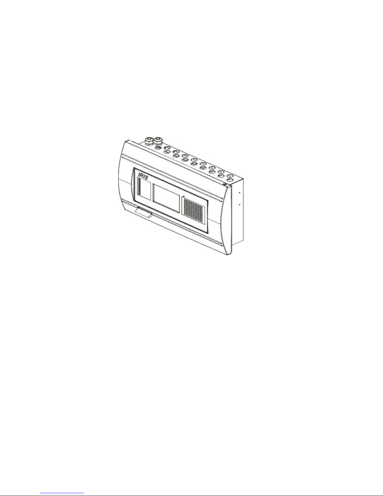
General view of the IRIS Fire Panel
1.2 General Specifications
The front panel consists of a graphic LCD display (dimensions 240x320) with a built-in touch screen and a
light-emitting diode indication. Separate operator and engineer passwords provide access to the functions of
the panel. The internal space of the box is protected with the help of secret screws.
One or two loop expanders can be supplemented to the mother board. Each one can control up to 198 addressable devices (99 modules and 99 detectors). In a configuration with two loops, the panel covers 396 addressable devices. The system can be expanded by connecting several fire panels IRIS to the Ethernet,
using TCP/IP for communication between them.
The panel has a built-in real time clock and calendar, allowing day and night time modes of work.
Switching over between the two modes can be automatic or manual. Events like FIRE, RESET, fault, etc.,
are saved in the memory, thereby creating an event log-file. It contains the time and date, the address of the
device, the type (module or detector), the name of the device, the zone, the name of the zone, etc.
Page 4

4 Fire Panel IRIS - Installation Manual
1.2.1 General Technical Specifications
• Loops - 1 or 2 loop versions as standard
• Up to 99 detectors and 99 modules per loop
• Zones - 96 displayed zones
• Inputs - 4 programmable for volt-free Normal Open contact
• Monitored relay outputs – 4 (Sounder, Fire, Fault and Fire Protection)
• Non monitored relay outputs – 4 programmable, 230V/ 10A
• Display – 320x240 CSTN graphic display (118.8mm X 89.38mm) with a touch panel
• Real time clock
• Up to 128 programmable Inputs/Outputs per panel
• Comprehensive day/night mode facility
• Simple Windows graphical configuration utility via Ethernet or USB
• Simple Http monitoring utility
• Loop less panel option (repeater)
• Thermal printer (optional)
• Digital communicator (optional)
• Flush mounting enclosure
• Multi-language support
• Easy software update
• Absolutely compatible with the requirements of EN54-2/4
1.2.2 Structure
Maximum configuration:
- Main PCB
- Power Source
- LED-indication
- Main Board
- 20 Relays Expander Module
- 2 Loop Controllers
- Modem
- Heat Printer
1.2.3 Environment
- Ambient Temperature: -5˚C up to +50˚C
- Relative Humidity: up to 95% (without condense)
- Storage Temperature: -10˚C up to +60˚C
- Weight (without the battery): 6kg.
1.2.4 Electrical Specifications
Earth connection
The earth connection has to be realized in accordance with the rules for the electrical safety with the total
resistance in the circuit lower than 10Ω. It is mandatory to connect the main power supply cable to the middle
input of the fire panel terminal - see §2.2.7 Power Source.
Main power supply
In normal operating conditions the fire panel is powered from the mains voltage line. In case of mains voltage line loss the fire panel is equipped with one rechargable battery. The characteristics of the main power
supply are as follows:
- Mail Power Supply: ~230V ±10%
- Frequency: 50/ 60Hz
- Electrical output: 1A
!
ATTENTION: Do not instal the fire panel near power electromagnetic fields (radio equipments, electric motors, etc.)!
Minimum configuration:
- Main PCB
- Power Supply
Page 5

Fire Panel IRIS - Installation Manual 5
Battery Power Supply
- Voltage output: Ucharge=13,8V
- Current output: Imax: 2A
- Number of the Batteries: 1, 12v/ 18Ah
- Battery Size: 167x181x76mm
- Type of the Battery connection: with a flat terminal lug - Ø5mm (M5)
List of the fuses
- General Power Supply: 2A, Slow Type
- Outputs: Sounder, Fire, Fault and Fire Protection - 0,5A, Self-recovering Type
- Battery: 10A, Automobile Type
List of the additional components, included in the set of the fire panel IRIS:
1. Fuse, Automobile Type, 10A - 1
2. Fuse 2A, Slow Type, for the Power Supply - 1
3. Balansing resistors, 10K - 4
4. Plastic taps - 21
5. Cable bandages - 2
6. Special Tool for unscrewing the secret bolts - 1
!
The panel should be installed by qualified specialists only.
The electronic components of the panel are vulnerable to electrostatic discharge.
Never add or turn off components which are being power supplied.
Page 6

6 Fire Panel IRIS - Installation Manual
2. INSTALLATION
2.1 Mounting
• The panel must be installed in a clean dry place and must not be subjected to impact orvibrations (Figure 1).
It must be situated far form heating appliances. The temperature must be within –5ºС and + 50ºC. The fire
panel is not water-proof!
• Unscrew the two secret bolts situated from above and from bellow the metal box with the help of the Special
Tool in the set - see Figure 2.
• Remove the front panel as first disconnect the flat-cable for panel indication. After that unscrew the hinge
bolts on the side of the front panel - Figure 3. (Note: You can unscrew and the hinge bolts on the side of the
metal box. The special here is the presence of two plastic pads situated under the hinges. The pads have to
be returned back under the hinges at closing the front pane.)
• Choose inlets for the cables, and put from the ptastic taps on those ones which you will not use.
Figure 1 Figure 2 Figure 3
2.1.1 Wall Mounting
• Use the templete in the set to fix the mounting holes of the metal box on the wall - see Figure 4.
• Drill holes (Ø6-8mm) on the wall and fix the metal
box - see Fig 5.
• Route the external cables onto the back box, make
off connection glands etc., BUT DO NOT make any
connections at this stage. ENTER THE MAINS CABLE THROUGH ITS OWN CABLE ENTRY POINT
AND KEEP MAINS WIRING AWAY FROM SYSTEM AND OTHER LOW VOLTAGE WIRING.
• Connect the mains supply and earth to the main
terminal block BUT DO NOT apply the main electrical supply at this stage.
• Position the accumulator battery in an upright
position and fix the metal clamp.
Figure 4 Figure 5
Page 7
Fire Panel IRIS - Installation Manual 7
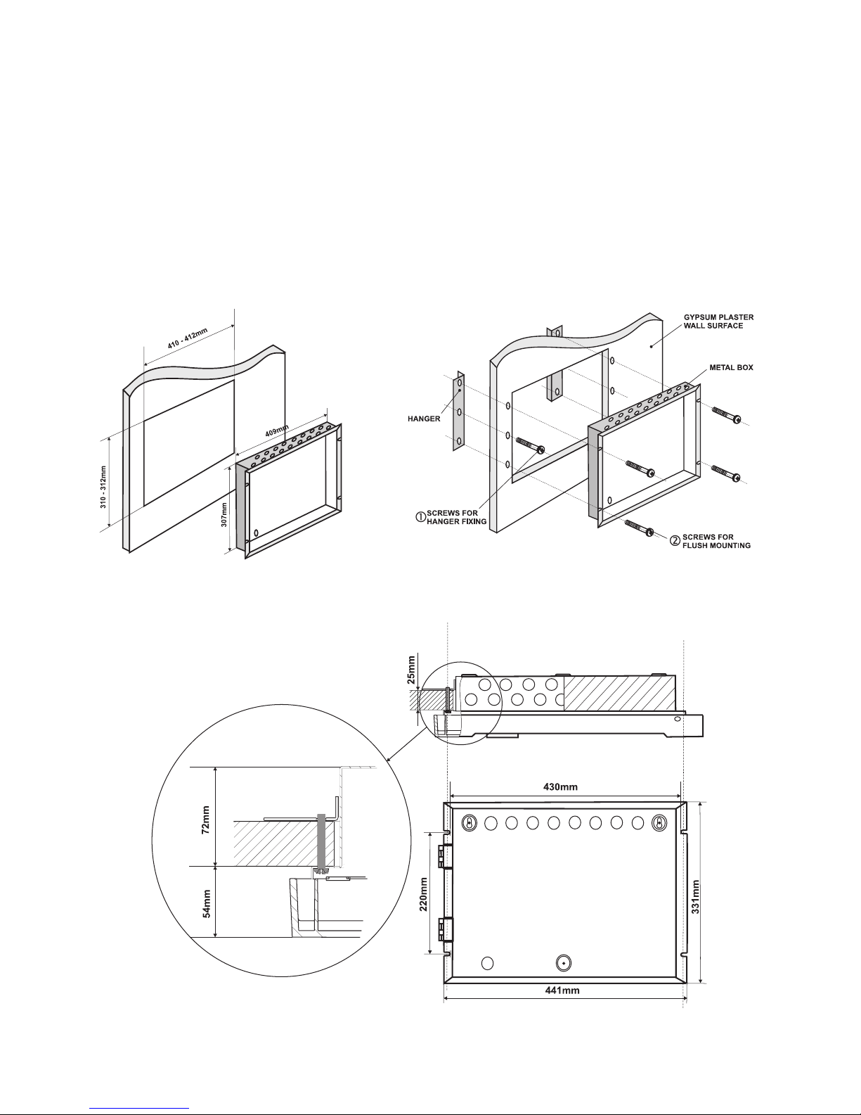
2.1.2 Flush Mounting
• Analogue-addressable fire panel IRIS is provided for flush mounting. In the set of the panel are included
two special hinges used for building-in the metal box of the panel in gypsum plaster walls with thickness up
to 25mm.
• Use given on Figure 6 dimentions to outline and to cut the mounting hole in the gypsum plaster wall.
• Fix the hinges on the back side of the gypsum plaster wall with suitable bolts, as shown on Figure 7, Position 1.
• Route the external cables onto the back box, make off connection glands etc., BUT DO NOT make any connections at this stage. ENTER THE MAINS CABLE THROUGH ITS OWN CABLE ENTRY POINT AND KEEP
MAINS WIRING AWAY FROM SYSTEM AND OTHER LOW VOLTAGE WIRING.
• Place the metal box in the mounting hole and fix it with suitable bolts - Figure 7, Position 2.
• Connect the mains supply and earth to the main terminal block BUT DO NOT apply the main electrical supply at this stage.
• Position the accumulator battery in an upright position and fix the metal clamp.
Figure 6. Dimentions of the metal box Figure 7. Action secuence for flush
and the mountig hole. mounting.
Figure 8. Flush mounting holes. Main view of the fix to the wall hinge and the bolts
supporting the metal box.
Page 8
8 Fire Panel IRIS - Installation Manual
2.2 System components
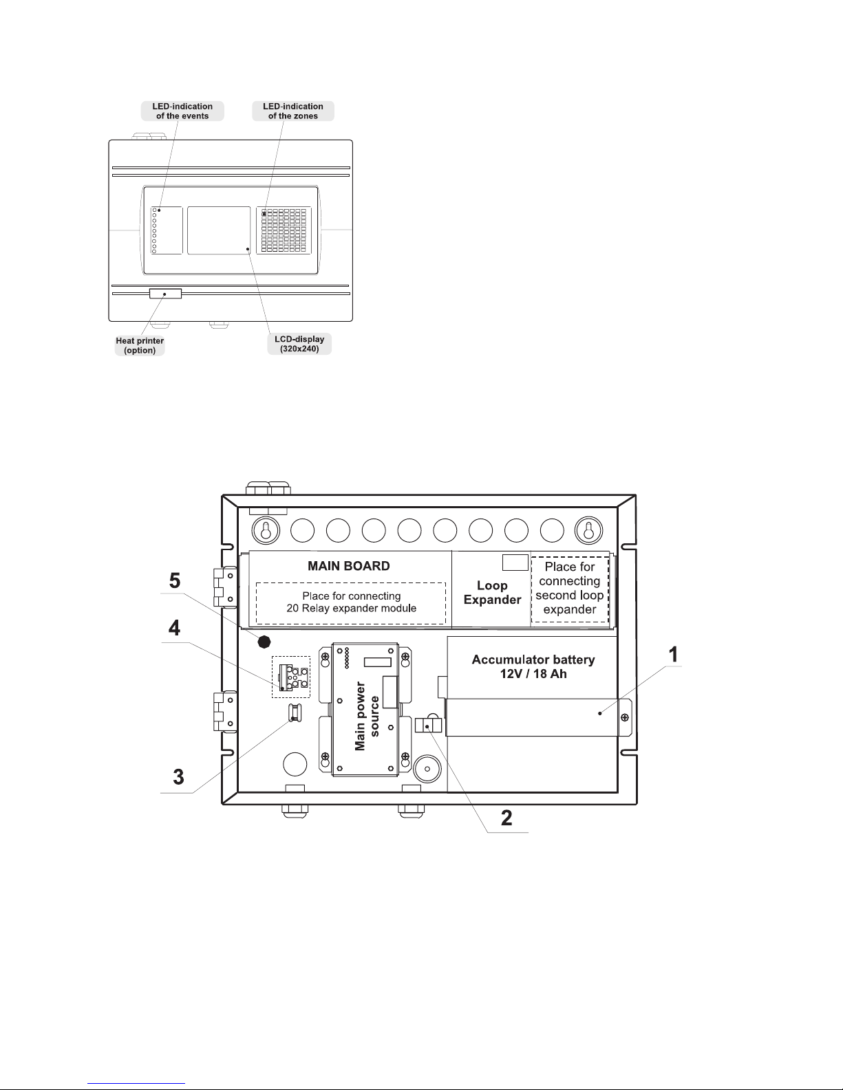
2.2.1 Front panel
Figure 9.
Main view of the front panel.
2.2.2 Configuration of the basic modules
Figure 10. Configuration of the basic modules in the system.
1 - Metal Clamp for supporting the accumulator battery.
2 - Terminal for connection between the accumulator battery and the main power source.
An automobile type fuse 10A is situated into the terminal.
3 - Clamp for supporting the main power supply cable.
4 - Terminal for connection between the mains power supply and the power source.
A slow type fuse 12A is situated into the terminal.
5 - Earthing lead.
LED-indication of the events provides following
functions:
1 - GENERAL FIRE
2 - PREALARM
3 - GENERAL FAULT
4 - SYSTEM FAULT
5 - SYSTEM SILENCE
6 - DELAY
7 - DISABLE
8 - TEST
9 - POWER ON
Page 9
Fire Panel IRIS - Installation Manual 9
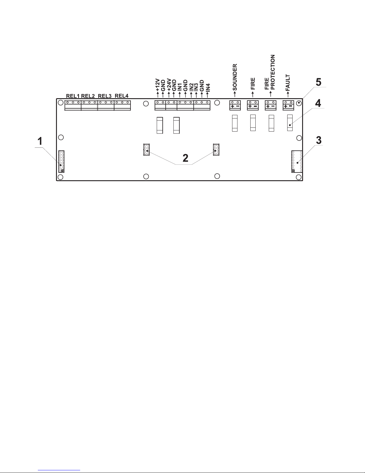
2.2.3 Main Board
The Main Board (Figure 11) is a basic part of the fire panel IRIS. Its function is to control the output devices
– sounders, fire detectors, signaling devices, etc. The Main Board could not work independently.
Figure 11 – General view of the Main Board of the fire panel.
· REL1, REL2, REL3 and REL4 – Programmable outputs, 230V / 10A;
·
+24V and +12V – DC power supply terminals;
·
GND – Common earth
·
IN1, IN2, IN3 and IN4 – Inputs (Each input is independent from the others);
· SOUNDER – Monitored output for connecting of a sounder, 24 VDC / 0,5 A;
· FIRE, FIRE PROTECTION and FAULT – Monitored outputs for connecting of different
devices (e.g. signaling devices), 24V / 0,5A;
1 - Flat-cable interface connector for front panel power supply;
2 - Flat-cable interface connectors for connecting 20 Relay Expander Module;
(At connecting 20 Relay Expander Module to the system configuration, the total number of
the programmable outputs increases to 24.)
3 - Flat-cable interface connector for connecting 20 Relay Expander Module;
4 - Fuse 0,5A, type Self-recovering;
5 - Mounting holes.
Page 10
10 Fire Panel IRIS - Installation Manual
IMPORTANT:
The relay of the respective programmable output only breaks the circuit (NC: The left termi-
nal lead) or closes the circuit (NO: The right terminal lead) according to the middle lead of
each terminal.
The relays of the programmable outputs just open or close the output circuit – there is no
difference in the potentials between the separate terminal leads!
At the monitored outputs Sounder, Fire Protection, Fire and Fault could be measured 24 VDC
and maximum output current 0,5A at closed relay contacts, ad 0V at open relay contacts.
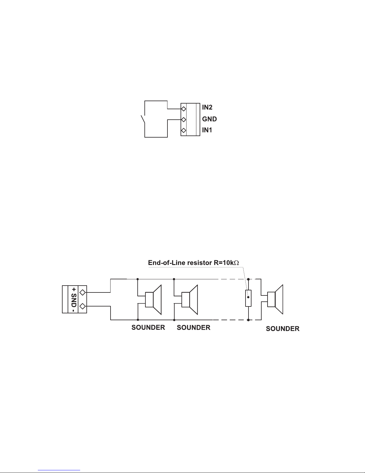
Figure 12 – Example for connecting
a button to inputs IN1 and IN2.
ATTENTION:
The active level of the input signal is logical zero!
To the monitored output Sounder could be connected several sounders – Figure 13. The maximum number
of sounders that could be connected in the circuit, depends on their total current consumption, which must
not exceed 0,5A.
Before connecting the last sounder in the circuit, parallel to it must be added end-of-line resistor 10k.
Figure 13. Connecting of sounders.
Page 11
Fire Panel IRIS - Installation Manual 11
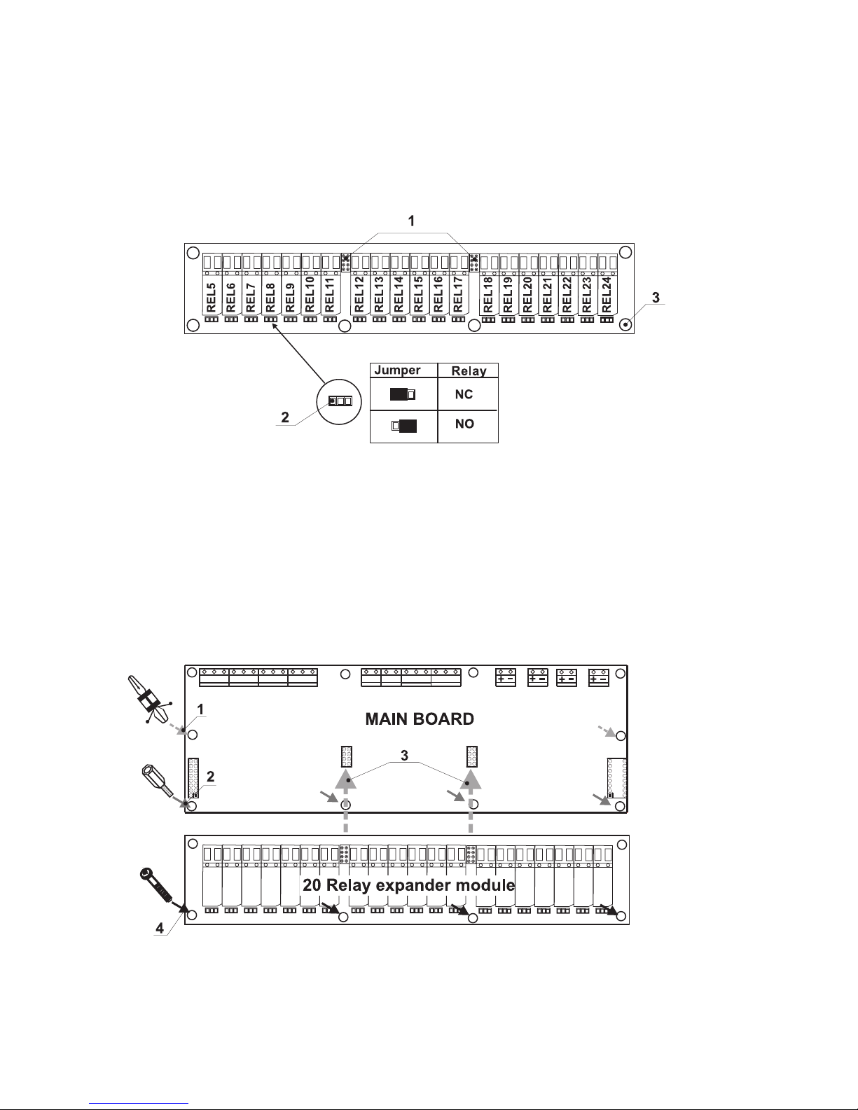
2.2.4 20 Relay Expander Module
20 Relay Expander Module (Figure 14.) is an additional module by which the total number of the programmable outputs increases to 24. The expander consists of 20 relays, controlling 20 separate outputs (110V /
1A) – numbered REL5 – REL24.
The function of the relays is just to open or close the output circuit according to their configuration (the posi
-
tion of the jumper).
It is possible the relay of the respective programmable output to open the circuit (NC: the left terminal lead)
or to close it (NO: the right terminal lead) according to the middle lead of each terminal.
Figure 14. General view of 20 Relay Expander Module.
• REL5 – REL24 – Programmable outputs, 110V / 1A;
• NC - Normally closed contact;
• NO - Normally open contact;
1 - Flat interface connectors for connecting 20 Relay expander module to the Main board;
2 - Jumper leads for programming the function of the respective relay – to open (NC) or to
close (NO) the circuit;
3 - Mounting holes for fixing the 20 Relay expander module to the Main board.
Adding of 20 Relay Expander Module to the Main Board of the fire panel
Figure 15.
1 – Place the mounting clips into the pointed holes, as shown on Figure 15.
2 – Screw the mounting supports into the pointed holes, as shown on Figure 15.
3 – Place 20 Relay expander module on the Main board, thus the flat interface connectors
on the both PCBs to connect to each other.
4 – Fix with suitable bolts 20 Relay expander module to the Main Board.
Page 12
12 Fire Panel IRIS - Installation Manual
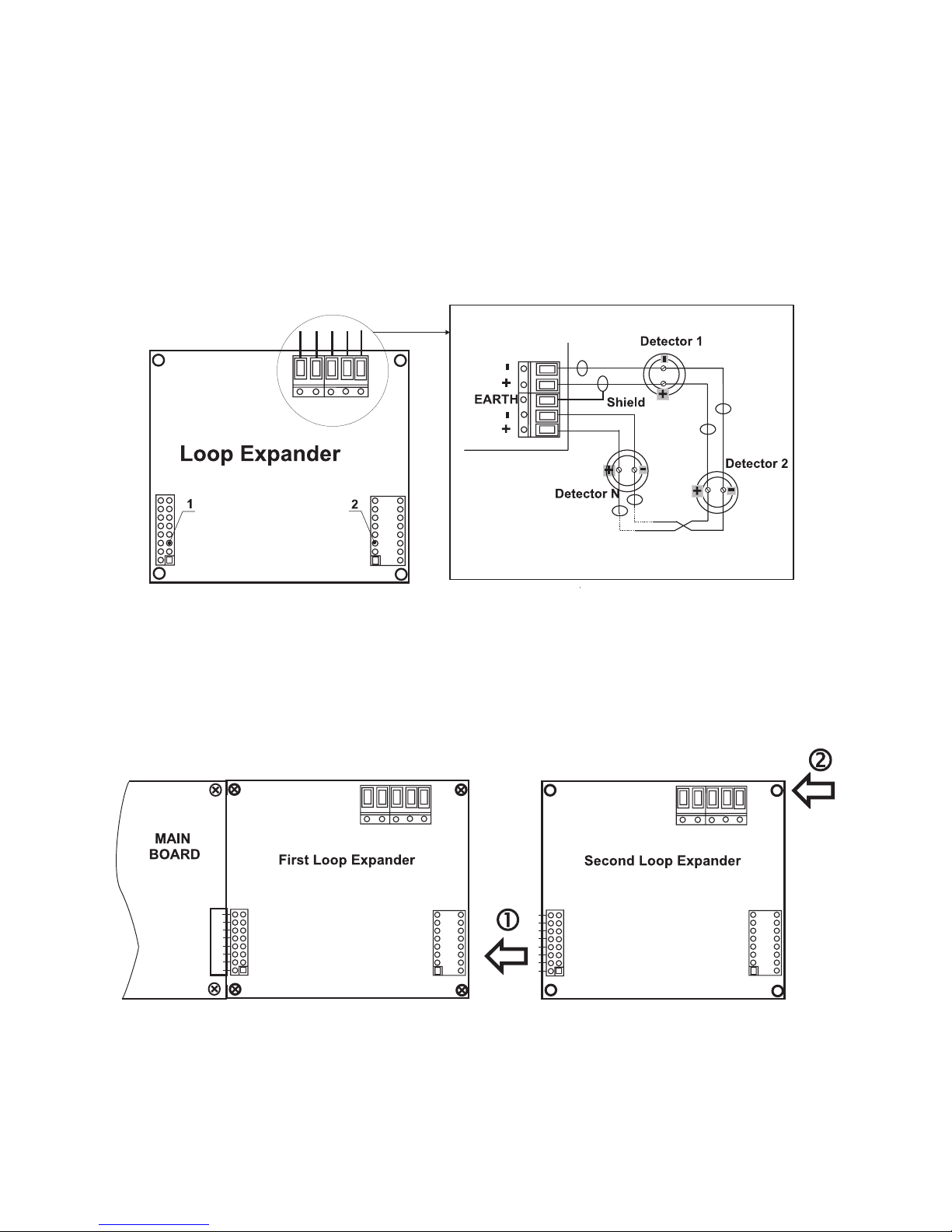
2.2.5 Loop Expander
The Loop Expander (Figure 16) realizes the connection between the Main Board and devices connected to
the communication line. The Loop Expander has two basic functions:
1. Gathers data from the devices in the communication line and transfers it to the Main Board.
2. Receives commands from the Main Board and transfers them to the devices connected in the
communication line.
In the configuration of analogue-addressable fire panel IRIS could be mounted two loop expanders, and thus
the maximum number of the addressable devices increases to 396.
To each loop expander could be connected up to 99 modules and 99 sensors. The maximum current con
-
sumption of the devices in the communication line is Imax = 700mA. If the consumption exceeds this value
an over-load protection would be turned on.
1 – Flat interface connector for connecting the Loop expander to the Main Board.
2 – Flat interface connector for connecting second loop expander.
Figure 16. General view of Loop Expander and an example for connecting devices to it.
Adding of second loop expander in the configuration of the fire panel IRIS
1 – Connect the flat interface connectors of the first and the second loop expanders.
2 – Fix the second loop expander with suitable bolts to the metal box of the fire panel.
Figure 17. Connecting of a second loop expander in the fire panel configuration.
Page 13
Fire Panel IRIS - Installation Manual 13
2.2.6 Maximum permissible cable length
The maximum length of the loop in the system could vary according to the cross-section and the ohmic resistance of the used cable. To make possible identifying devices with identical addresses (double addresses) in
the system configuration, the cable resistance should not exceed definite calculated value. According to the
ohmic cable resistance, calculate:
· Formula 1: L
C1MAX
= 21 / RC · Formula 2: L
C2MAX
= 80 / RC,
Where:
L
C1MAX
and L
C2MAX
- are maximum permissible length of the used cabel, [km];
RC - is total ohmic resistance of the two wires of the used able; its value shows the magnitude of the cable
resistance at length 1km [Ω/km].
If L
C
is the necessary length of the cable used in the loop, then:
· At LC ≤ L
C1MAX
- the fire pane will be able to communicate with the devices in the circuit and also will
be able to identify the presence of double address.
· At L
C1MAX
< LC ≤ L
C2MAX
- the fire panel will be able to communicate with the devices in the circuit
but will not be able to identify the presence of double addresses.
· At LC > L
C2MAX
- the fire panel will not be able neither to communicate with the devices nor to identify
the presence of double addresses.
Example:
RC = 39 Ω/km, then
L
C1MAX
= 21 / RC = 21 / 39 ≈ 0,540km
L
C2MAX
= 80 / RC = 80 / 39 ≈ 2km
LC = 1km
In this case it is possible to use the chosen cable in the system, but the fire panel will not be able to identify
devices with double addresses. If this could not satisfying the requirements of the system it must be chosen
cable with lower ohmic resistance RC.
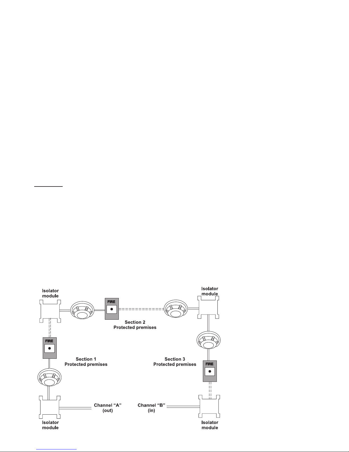
The connection diagram shown on Figure 18, gives the possibility to protect devices against opening and
short-circuit. For example, short-circuit in section 2 will not influence the operation of sections 1 and 3. The
isolator modules at the both ends of section 2 will isolate it, and section 1 and 3 will continue working properly,
as section 1 will operate by supply from the channel “A” and section 3 – by supply from channel “B”. Since
the fire panel will not be able to communicate with the devices from section 2, it will generate an alarm signal
for lost devices and open circuit.
Figure 18.
IMPORTANT
:
The maximum number of
devices between two isolator modules is 30!
Page 14
14 Fire Panel IRIS - Installation Manual
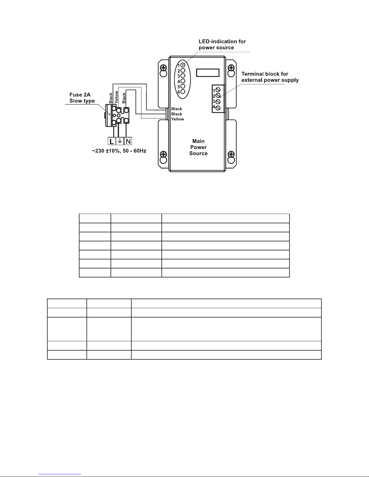
2.2.7 Main Power Source
Figure 19. General view of the power source and the terminal.
LED-indication of the power source
LED Function Description
1 AC LOSS Main power supply loss.
2 Charger Fault Problem with the battery charging.
3 BATT LOSS Battery loss.
4 BATT Low Discharged battery.
5 EARTH FAULT Earth connection ≤ 10kΩ.
6 Rx / Tx Shows the communication with the panel.
Terminal Block for connecting to external power supply.
Terminal Function Description
1 GND Input for connectin of external power supply EARTH.
2 FAULT OUT Fault output, turns on when a problem with the main power supply
occurred. Connect it to the input (Fault In) of the external power
supply.
3 FAULT IN Input for connecting the Fault output of the external power supply.
4 +13.8V External power supply input.
!
Before the mains supply is switched on, check the correct connection of each loop, sounder
or any other input or output.
Page 15
Fire Panel IRIS - Installation Manual 15
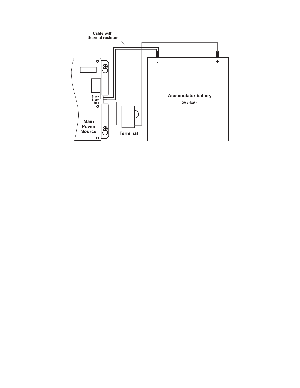
2.2.8 Connecting of the accumulator battery
Figure 20. Connecting the accumulator battery to the main power source.
· Connect the red cable to the positive pole of the battery, the black cable – to the negative battery
pole. Both of the cables are connected to the battery by means of a flat terminal lug Ø5mm.
· Connect the cable with the built-in thermo resistor to the negative battery pole.
· Check the presence and proper working of the automobile fuse 10A, situated in the terminal for
connection between the battery and the power source.
!
Important: Never cut or shorten the cable with the built-in thermo resistor! That will cause
harm to the normal charging process of the battery!
ATTENTION: The connection between the accumulator battery and the main power source has some spe-
cial features. It is strongly recommended to use only battery with electrical characteristics and dimensions
pointed from the manufacturer. Before connecting to the power source check the polarity of the battery. The
battery cannot power up the panel before the mains supply has been switched on. Connect the battery after
the mains supply is turned on. If the battery is new it will take a few hours before its complete charging!
The charging of the accumulator battery is done at maximum current Imax = 2A and charging voltage Ucha
-
rge < 13,8V.
The charging of the battery depends on its temperature. The temperature is monitored by means of
a thermo-resistor build-in the black cable without flat terminal lug at the end – Figure 20. Never cut
or shorten the cable with the built-in thermo resistor, because that will harm the normal charging of
the battery!
Page 16
16 Fire Panel IRIS - Installation Manual
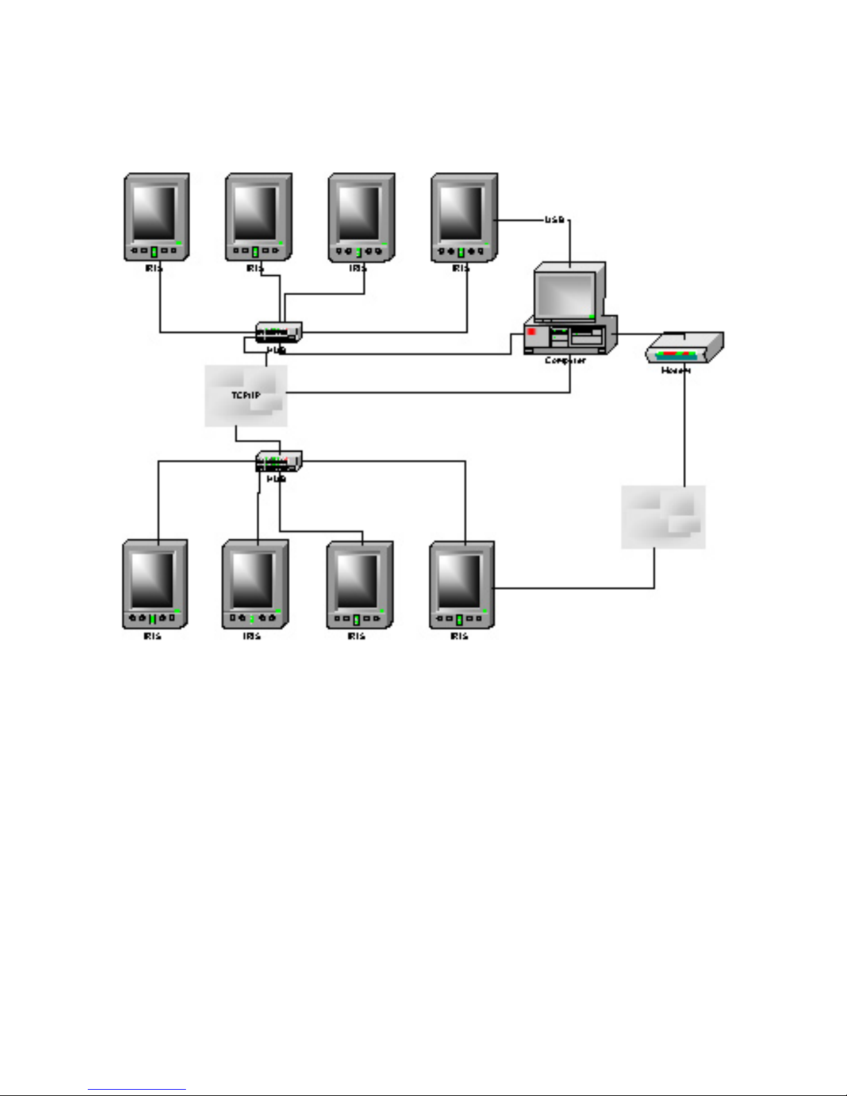
2.3. Network connection diagram
It is possible to connect some individual IRIS fire panels in a network by means of a HUB and TCP/IP protocol – Figure 21. A supervisor PC, which could follow the current status of the individual fire panels, monitors
the current panel state. As an option, it is possible connecting of a modem, which allows connecting of the
supervisor PC with other remote devices (in other cities, countries, etc.).
Figure 21.
Page 17

Fire Panel IRIS - Installation Manual 17
3. PROGRAMMING
When turned on, the panel always conducts a procedure of loading the parameters, which usually takes
about 30 sec. There is no access to the menus of the panel during that procedure.
Upon the initial start up, the panel does not hold any configurations. Initialization may take several minutes.
The initialization time needed depends on the number of periphery and loop devices. After the panel has
been turned on, it performs a procedure for detecting newly installed periphery and loop devices.
The general view of the CONFIGURATION Menu of IRIS Fire Panel is shown on Fig. Screen 1. It gives the
installer the possibility to choose the type of the operation, which is necessary to do:
1. To program system parameters – Programming Menu.
2. To study the panel operation, as to enter different parameters for the maintenance of the system – Main
-
tenance Menu.
Fig. Screen 1.
3.1 Programming Menu
To enter in the Programming Menu the installer has to choose button “Programming”. The general view of
the menu is shown on Fig. Screen 2.
Fig. Screen 2.
On the left side of the screen are located buttons for entering submenus for parameter programming of Devices, Zones, Inputs, Outputs and Access Codes. To enter a desired submenu just choose it button.
Choosing the button “Restore Defaults” on the left side of the screen can restore all the factory settings.
Button “Save” is for quick saving of the entered information.
With the button “Exit” in the bottom left corner the user/installer can easy move one step back on the
previous screen.
Page 18

18 Fire Panel IRIS - Installation Manual
3.2 Devices
In the addressable fire panel IRIS are supported periphery and loop devices. With choosing the “Device” button the user/installer enters a menu for choosing the type of the device – Fig. Screen 3.
Fig. Screen 3.
3.2.1 Periphery Devices
Choosing “Periphery Device” button leads to submenu for entering the parameters of the available periphery
devices in the system configuration – Fig. Screen 4. List of 1.0 version supported periphery devices:
· PSU140 Power source
· IO4 (Main Board) - 4 input/ 4 monitored outputs/ 4 relays
· IO24 (Main Board + 20 Relay Expander Module) - 4 input/ 4 monitored outputs/ 24 relays
· LOOP1 (First Loop expander) / LOOP2 (Second Loop expander)
Upon detecting a new periphery device (which is missing in the configuration), the following message will be
displayed: “NEW PERIPHERY DEVICES FOUND”, and the number of the detected devices will be indicated.
All new periphery devices have to be added to the panel configuration using the SAVE command for the spe
cific device or the general SAVE command from the CONFIGURATION menu – Fig. Screen 2. Any devices,
not configured in the panel, shall not generate any messages. Where a periphery device is removed, the
panel shall display “PERIPHERY DEVICE FAULT”. In the case of an unregistered device, the panel reduces
the number of new devices, and if their number is 0 it will stop displaying the “NEW PERIPHERY DEVICES
FOUND” notice. The device can be deleted from the configuration of the panel with the REMOVE command
for the specific device. Where a device of a different type is placed in position on the panel of a given device
from the configuration, the panel shall display “PERIPHERY DEVICE TYPE ERROR”. In order to replace a
previous device with a new type, choose the REPLACE button for the specific device.
Fig. Screen 4.
Page 19

Fire Panel IRIS - Installation Manual 19
3.2.1.1 Physical Address of Periphery Device
The panel is able to operate with up to 5 periphery devices, addressed 1 to 5. The devices can be self-addressed, whereby the first along the link acquires the lowest address. The power supply always acquires
address 1.
3.1.1.2 Button for Entering the Device Submenu
There is a menu for each periphery device which displays its current configuration and parameters. On Fig.
Screen 5 is shown the submenu of the first periphery device in the panel configuration (Power source PSU),
where it is possible to follow the current information for the main and additional power supply. On Fig. Screen
6 is shown the submenu of the second device in the system configuration (Main board – I/O4, or Main board +
20 Relay Expander – I/O24), and on Fig. Screen 7 – the third available periphery device (First Loop expander
– LOOP1).
Fig. Screen 5 – PSU (Power source)
Fig. Screen 6 – I/O24 (Main board + 20 Relay Expander Module)
Page 20

20 Fire Panel IRIS - Installation Manual
Fig. Screen 7 – LOOP1 (First Loop expander)
3.2.1.3 Current Status of the Device
The running status of the device can be:
NORMAL – the device is properly operating.
NEW – the device is new to the system. It must be saved.
FAULT – the device does not respond.
TYPE ERROR – a device, different from that saved, has been detected.
EMPTY – no device has been detected at this address.
3.2.2 Loop Devices
The device searches for new loop devices only when the respective loop controller has been added to the
configuration. To enter the submenu for programming of the loop devices parameters from “Device” menu
choose button “Loop Devices” – Fig. Screen 3.
When a new loop device is found (missing in the configuration) the message “NEW LOOP DEVICES FOUND”
will be generated, as well as the number of detected devices. The message is generated by loops. Adding a
new device to the configuration is accomplished with the APPLY command from the specific device menu or
with the help of the general SAVE command from the
Programming menu. Any device, which has not been
added to the configuration, cannot generate messages. In case of removal of a loop device, the panel generates a ”LOOP DEVICE FAULT” message. When a newly detected device is removed, the panel reduces the
number of the new devices and if their number is 0 it shall extinguish the “NEW LOOP DEVICES FOUND”
message. Removing the device from the configuration is accomplished with the REMOVE command in the
menu for the specific device.
Where in abundance, it is possible for device addresses to double along the loops (see also §2.2.6 Maximum
permissible cable length). In such cases the message “DOUBLE ADDRESS” will be displayed along with
the problem address. Should a different device type appear at the address of a saved device, the panel will
generate “LOOP DEVICE TYPE ERROR”. The new device can be saved by selecting the correct type from
the menu of types and the APPLY command in the menu for the specific device.
The panel cannot distinguish the types of devices in one and the same area. This requires each type of de
-
vice to be further defined by the installer. For ease of introduction, the panel suggests possible devices for se
lection. Information for correspondence of the device types is given in §3.2.2.12 Maintained Loop Devices
and Appendix B – Tables for correspondence of the device types.
Page 21
Fire Panel IRIS - Installation Manual 21
The “SAVE” button can be used for fast configuration of the device. Following this command, the panel sets
up all detected loop and periphery devices by default. New devices only are configured under this command.
The “RESTORE DEFAULTS” command deletes all system parameters.
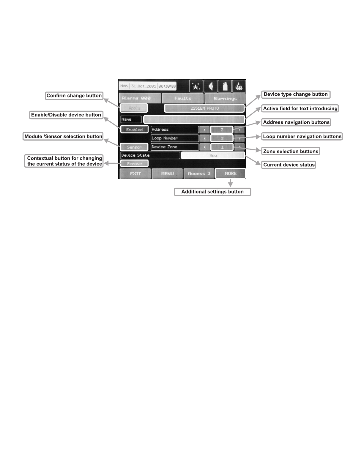
On Fig. Screen 8 is given the general view of the submenu for new loop devices configuration.
Fig. Screen 8.
3.2.2.1 Confirm Change Button
Saves changes in the permanent memory.
3.2.2.2 Button to enable/disable a device
See 5.10.2
3.2.2.3 Module or detector selection button
This button is used to switch over between module and detector addresses.
3.2.2.4 Address Navigation Button
This button helps to screen (in sequence or directly) the devices of one and the same loop.
3.2.2.5 Loop Number Navigation Button
These keys alternate the loop (in sequence or directly) of the screened devices.
3.2.2.6 Zone Selection Button
These keys alternate the zone (in sequence or directly) to which the device belongs.
3.2.2.7 Current Device Status
The current device status varies according to the device type.
3.2.1.8 Button for Changing the Current Status of the Device
The action of this button depends on the type of current status of the device. The following are possible:
REMOVE – deletes the device from the configuration.
SAVE – saves the new device in the configuration.
REPLACE – replaces the device type.
3.2.2.9 Change Device Type Button
Press this button for the panel to provide a compatibility device list of which to choose the most suitable one.
The “SELECT NEW DEVICE TYPE” message will be portrayed Fig. Screen 9.
Page 22

22 Fire Panel IRIS - Installation Manual
3.2.2.10 Active Field for Text Introduction
Choosing this field accesses the text introduction mode. The text must not exceed 40 digits together with the
spaces – Fig. Screen 10. Entered information is confirmed with button .
Figure Screen 9. Figure Screen 10.
3.2.2.11 Additional Settings Button
The additional adjustments vary according to the type of device. Setting the day and nighttime mode, as and
setting the levels of the alarm signal (FIRE) – Fig. Screen 11, is performed by pressing of the respective button and entering of the desired value by means of an additional keypad displayed on the screen.
Fig. Screen 11.
Page 23

Fire Panel IRIS - Installation Manual 23
3.2.2.12 Maintained Loop devices
(See also APPENDIX B: Tables for corresponding of device types)
3.2.2.12.1 - 1251E (Ionization sensor)
- Following the initial start-up of the system there is no need for further readjustment of the type.
- A number should be set for the zone (1-96), to which the messages from the specific device will be sent,
indicating: ALARM, TROUBLE, etc.
- A specific mode is assigned to the light-emitting diode of the device: BLINK and OFF. In the BLINK mode the
LED blinks at every query addressed by the system. In the OFF mode the LED does not reflect any device
contact. The LED turns ON in case of a FIRE signal.
- Introduce the name of the device – 40 digits.
- The device maintains day and nighttime working modes. Each of these are assigned different times of filtra
tion of the FIRE signal. The nighttime mode must be less than that of the daytime mode. For specific cases
the times of both modes can be 0, disallowing filtration time, having the fire signal is immediately perceived.
The device maintains day and nighttime working modes. Both are assigned different thresholds for FIRE
(1-3). Nighttime mode must be of a lower threshold than that of the daytime one. It is possible to experiment
with various alarm levels.
3.2.2.12.2 - 2251EM (Photoelectric Smoke sensor)
- Following the initial start-up of the system there is no need for further readjustment of the type.
- A number should be set for the zone (1-96), to which the messages from the specific device will be sent,
indicating: ALARM, TROUBLE, etc.
- A specific mode is assigned to the light-emitting diode of the device: BLINK and OFF. In the BLINK mode the
LED blinks at every query addressed by the system. In the OFF mode the LED does not reflect any device
contact. The LED turns ON in case of a FIRE signal.
- Introduce the name of the device – 40 digits.
- The device maintains day and nighttime working modes. Each of these are assigned different times of filtra
tion of the FIRE signal. The nighttime mode must be less than that of the daytime mode. For specific cases
the times of both modes can be 0, disallowing filtration time, having the fire signal is immediately perceived.
The device maintains day and nighttime working modes. Both are assigned different thresholds for FIRE
(1-3). Nighttime mode must be of a lower threshold than that of the daytime one. It is possible to experiment
with various alarm levels.
3.2.2.12.3 - 2251EIS (Photoelectric Smoke sensor)
- After the initial starting up of the system the type needs to be fine-tuned. The panel shall detect devices like
2251ЕМ. From the menu of types select the correct type of the respective device (this is recommended in
order to ensure the proper performance of the device).
- A number should be set for the zone (1-96), to which the messages from the specific device will be sent,
indicating: ALARM, TROUBLE, etc.
- A specific mode is assigned to the light-emitting diode of the device: BLINK and OFF. In the BLINK mode the
LED blinks at every query addressed by the system. In the OFF mode the LED does not reflect any device
contact. The LED turns ON in case of a FIRE signal.
- Introduce the name of the device – 40 digits.
- The device maintains day and nighttime working modes. Each of these are assigned different times of filtra
tion of the FIRE signal. The nighttime mode must be less than that of the daytime mode. For specific cases
the times of both modes can be 0, disallowing filtration time, having the fire signal is immediately perceived.
3.2.2.12.4 – 6200 (Smoke beam sensor)
- After the initial starting up of the system the type needs to be fine-tuned. The panel shall detect devices like
2251ЕМ. From the menu of types select the correct type of the respective device (this is recommended in
order to ensure the proper performance of the device).
- A number should be set for the zone (1-96), to which the messages from the specific device will be sent,
indicating: ALARM, TROUBLE, etc.
- A specific mode is assigned to the light-emitting diode of the device: BLINK and OFF. In the BLINK mode the
LED blinks at every query addressed by the system. In the OFF mode the LED does not reflect any device
contact. The LED turns ON in case of a FIRE signal.
- Introduce the name of the device – 40 digits.
Page 24

24 Fire Panel IRIS - Installation Manual
- The device maintains day and nighttime working modes. Each of these are assigned different times of filtration of the FIRE signal. The nighttime mode must be less than that of the daytime mode. For specific cases
the times of both modes can be 0, disallowing filtration time, having the fire signal is immediately perceived.
3.2.2.12.5 - FTX-P1 (Photoelectric Smoke sensor)
- After the initial starting up of the system the type needs to be fine-tuned. The panel shall detect devices like
2251ЕМ. From the menu of types select the correct type of the respective device (this is recommended in
order to ensure the proper performance of the device).
- A number should be set for the zone (1-96), to which the messages from the specific device will be sent,
indicating: ALARM, TROUBLE, etc.
- A specific mode is assigned to the light-emitting diode of the device: BLINK and OFF. In the BLINK mode the
LED blinks at every query addressed by the system. In the OFF mode the LED does not reflect any device
contact. The LED turns ON in case of a FIRE signal.
- Introduce the name of the device – 40 digits.
- The device maintains day and nighttime working modes. Each of these are assigned different times of filtra
tion of the FIRE signal. The nighttime mode must be less than that of the daytime mode. For specific cases
the times of both modes can be 0, disallowing filtration time, having the fire signal is immediately perceived.
3.2.2.12.6 – 6500 (Linear smoke sensor)
- After the initial starting up of the system the type needs to be fine-tuned. The panel shall detect devices like
2251ЕМ. From the menu of types select the correct type of the respective device (this is recommended in
order to ensure the proper performance of the device).
- A number should be set for the zone (1-96), to which the messages from the specific device will be sent,
indicating: ALARM, TROUBLE, etc.
- A specific mode is assigned to the light-emitting diode of the device: BLINK and OFF. In the BLINK mode the
LED blinks at every query addressed by the system. In the OFF mode the LED does not reflect any device
contact. The LED turns ON in case of a FIRE signal.
- Introduce the name of the device – 40 digits.
- The device maintains day and nighttime working modes. Each of these are assigned different times of filtra
tion of the FIRE signal. The nighttime mode must be less than that of the daytime mode. For specific cases
the times of both modes can be 0, disallowing filtration time, having the fire signal is immediately perceived.
- The device can be tested by covering the reflector, depending on the selected alarm level. As a result a
FIRE signal is generated to the respective zone. In the case of complete blockage of the reflector a “BEAM
BLOCKAGE” message is generated. If there are any reflective objects in the path of the detector a “SIGNAL
OVER RANGE” message is generated.
3.2.2.12.7 - 5251EM (Temperature sensor)
- Following the initial start-up of the system there is no need for further readjustment of the type.
- A number should be set for the zone (1-96), to which the messages from the specific device will be sent,
indicating: ALARM, TROUBLE, etc.
- A specific mode is assigned to the light-emitting diode of the device: BLINK and OFF. In the BLINK mode the
LED blinks at every query addressed by the system. In the OFF mode the LED does not reflect any device
contact. The LED turns ON in case of a FIRE signal.
- Introduce the name of the device – 40 digits.
- The device maintains day and nighttime working modes. Each of these are assigned different times of filtra
tion of the FIRE signal. The nighttime mode must be less than that of the daytime mode. For specific cases
the times of both modes can be 0, disallowing filtration time, having the fire signal is immediately perceived.
3.2.2.12.8 - 5251TEM (Temperature sensor)
- After the initial starting up of the system the type needs to be fine-tuned. The panel shall detect devices like
5251ЕМ. From the menu of types select the correct type of the respective device (this is recommended in
order to ensure the proper performance of the device).
- A number should be set for the zone (1-96), to which the messages from the specific device will be sent,
indicating: ALARM, TROUBLE, etc.
- A specific mode is assigned to the light-emitting diode of the device: BLINK and OFF. In the BLINK mode the
LED blinks at every query addressed by the system. In the OFF mode the LED does not reflect any device
contact. The LED turns ON in case of a FIRE signal.
- Introduce the name of the device – 40 digits.
Page 25

Fire Panel IRIS - Installation Manual 25
- The device maintains day and nighttime working modes. Each of these are assigned different times of filtration of the FIRE signal. The nighttime mode must be less than that of the daytime mode. For specific cases
the times of both modes can be 0, disallowing filtration time, having the fire signal is immediately perceived.
3.2.2.12.9 - 5251HTEM (Temperature sensor)
- After the initial starting up of the system the type needs to be fine-tuned. The panel shall detect devices like
5251ЕМ. From the menu of types select the correct type of the respective device (this is recommended in
order to ensure the proper performance of the device).
- A number should be set for the zone (1-96), to which the messages from the specific device will be sent,
indicating: ALARM, TROUBLE, etc.
- A specific mode is assigned to the light-emitting diode of the device: BLINK and OFF. In the BLINK mode the
LED blinks at every query addressed by the system. In the OFF mode the LED does not reflect any device
contact. The LED turns ON in case of a FIRE signal.
- Introduce the name of the device – 40 digits.
- The device maintains day and nighttime working modes. Each of these are assigned different times of filtra
tion of the FIRE signal. The nighttime mode must be less than that of the daytime mode. For specific cases
the times of both modes can be 0, disallowing filtration time, having the fire signal is immediately perceived.
3.2.2.12.10 - 2251TEM (Multi-criteria fire sensor)
- Following the initial start-up of the system there is no need for further readjustment of the type.
- A number should be set for the zone (1-96), to which the messages from the specific device will be sent,
indicating: ALARM, TROUBLE, etc.
- A specific mode is assigned to the light-emitting diode of the device: BLINK and OFF. In the BLINK mode the
LED blinks at every query addressed by the system. In the OFF mode the LED does not reflect any device
contact. The LED turns ON in case of a FIRE signal.
- Introduce the name of the device – 40 digits.
- The device maintains day and nighttime working modes. Both are assigned different thresholds for FIRE (1-
6). Threshold 6 responds to an alarm signal sent from a thermal detector. It is recommended that threshold 6
be selected for daytime mode. Nighttime mode must be of a lower threshold than that of the daytime one. It
is possible to experiment with various alarm levels.
The day and nighttime working modes are assigned different times of filtration of the FIRE signal.
The nighttime mode must be less than that of the daytime mode. For specific cases the times of both modes
can be 0, disallowing filtration time, having the fire signal is immediately perceived.
3.2.2.12.11 – 7251 (Photoelectric smoke sensor)
- Following the initial start-up of the system there is no need for further readjustment of the type.
- A number should be set for the zone (1-96), to which the messages from the specific device will be sent,
indicating: ALARM, TROUBLE, etc.
- A specific mode is assigned to the light-emitting diode of the device: BLINK and OFF. In the BLINK mode the
LED blinks at every query addressed by the system. In the OFF mode the LED does not reflect any device
contact. The LED turns ON in case of a FIRE signal.
- Introduce the name of the device – 40 digits.
- The device maintains day and nighttime working modes. Both are assigned different thresholds for FIRE
(1-9). Nighttime mode must be of a lower threshold than that of the daytime one. It is possible to experiment
with various alarm levels.
The day and nighttime working modes are assigned different times of filtration of the FIRE signal.
The nighttime mode must be less than that of the daytime mode. For specific cases the times of both modes
can be 0, disallowing filtration time, having the fire signal is immediately perceived.
3.2.2.12.12 - M210E (Single input)
- Following the initial start-up of the system there is no need for further readjustment of the type.
- A number should be set for the zone (1-96), to which the messages from the specific device will be sent,
indicating: ALARM, TROUBLE, etc.
- A specific mode is assigned to the light-emitting diode of the device: BLINK and OFF. In the BLINK mode the
LED blinks at every query addressed by the system. In the OFF mode the LED does not reflect any device
contact. The LED turns ON in case of activation at the input.
- Introduce the name of the device – 40 digits.
Page 26

26 Fire Panel IRIS - Installation Manual
3.2.2.12.13 - M220E (Dual input)
- After the initial starting up of the system the type needs to be fine tuned. The panel shall detect devices
like М210E. From the menu of types select the correct type of the respective device (this is recommended in
order to ensure the proper performance of the device).
- A number should be set for the zone (1-96), to which the messages from the specific device will be sent,
indicating: ALARM, TROUBLE, etc.
- A specific mode is assigned to the light-emitting diode of the device: BLINK and OFF. In the BLINK mode the
LED blinks at every query addressed by the system. In the OFF mode the LED does not reflect any device
contact. The LED turns ON in case of activation at the input.
- Introduce the name of the device – 40 digits.
3.2.2.12.14 - M221EINPUT (Input)
- After the initial starting up of the system the type needs to be fine-tuned. The panel shall detect devices
like М210E. From the menu of types select the correct type of the respective device (this is recommended in
order to ensure the proper performance of the device).
- A number should be set for the zone (1-96), to which the messages from the specific device will be sent,
indicating: ALARM, TROUBLE, etc.
- A specific mode is assigned to the light-emitting diode of the device: BLINK and OFF. In the BLINK mode the
LED blinks at every query addressed by the system. In the OFF mode the LED does not reflect any device
contact. The LED turns ON in case of activation at the input.
- Introduce the name of the device – 40 digits.
3.2.2.12.15 - M221EOUTPUT (output)
- After the initial starting up of the system the type needs to be fine tuned. The panel shall detect devices
like М210E. From the menu of types select the correct type of the respective device (this is recommended in
order to ensure the proper performance of the device).
- A number should be set for the zone (1-96), to which the messages from the specific device will be sent,
indicating: ALARM, TROUBLE, etc.
- A specific mode is assigned to the light-emitting diode of the device: BLINK and OFF. In the BLINK mode the
LED blinks at every query addressed by the system. In the OFF mode the LED does not reflect any device
contact. The LED turns ON in case of activation at the output.
- Introduce the name of the device – 40 digits.
3.2.2.12.16 - M201E (Main switch output)
- Following the initial start-up of the system there is no need for further readjustment of the type.
- A number should be set for the zone (1-96), to which the messages from the specific device will be sent,
indicating: ALARM, TROUBLE, etc.
- A specific mode is assigned to the light-emitting diode of the device: BLINK and OFF. In the BLINK mode the
LED blinks at every query addressed by the system. In the OFF mode the LED does not reflect any device
contact. The LED turns ON in case of activation at the input.
- Introduce the name of the device – 40 digits.
3.2.2.12.17 - M501ME (Input)
- After the initial starting up of the system the type needs to be fine tuned. The panel shall detect devices
like М210E. From the menu of types select the correct type of the respective device (this is recommended in
order to ensure the proper performance of the device).
- A number should be set for the zone (1-96), to which the messages from the specific device will be sent,
indicating: ALARM, TROUBLE, etc.
- A specific mode is assigned to the light-emitting diode of the device: BLINK and OFF. In the BLINK mode the
LED blinks at every query addressed by the system. In the OFF mode the LED does not reflect any device
contact. The LED turns ON in case of activation at the input.
- Introduce the name of the device – 40 digits.
3.2.2.12.18 - M503ME (Micro monitor)
- After the initial starting up of the system the type needs to be fine-tuned. The panel shall detect devices
like М210E. From the menu of types select the correct type of the respective device (this is recommended in
order to ensure the proper performance of the device).
- A number should be set for the zone (1-96), to which the messages from the specific device will be sent,
indicating: ALARM, TROUBLE, etc.
Page 27

Fire Panel IRIS - Installation Manual 27
- A specific mode is assigned to the light-emitting diode of the device: BLINK and OFF. In the BLINK mode the
LED blinks at every query addressed by the system. In the OFF mode the LED does not reflect any device
contact. The LED turns ON in case of activation at the input.
- Introduce the name of the device – 40 digits.
3.2.2.12.19 - M500KAC (Call point)
- After the initial starting up of the system the type needs to be fine tuned. The panel shall detect devices
like М210E. From the menu of types select the correct type of the respective device (this is recommended in
order to ensure the proper performance of the device). On a correct adjustment of the type, after activation
of a Call Point is generated an alarm signal to the relevant device.
- A number should be set for the zone (1-96), to which the messages from the specific device will be sent,
indicating: ALARM, TROUBLE, etc.
- A specific mode is assigned to the light-emitting diode of the device: BLINK and OFF. In the BLINK mode the
LED blinks at every query addressed by the system. In the OFF mode the LED does not reflect any device
contact. The LED turns ON in case of activation at the input.
- Introduce the name of the device – 40 digits.
3.2.2.12.20 - M512ME (Zone monitor)
- Following the initial start-up of the system there is no need for further readjustment of the type.
- A number should be set for the zone (1-96), to which the messages from the specific device will be sent,
indicating: ALARM, TROUBLE, etc.
- A specific mode is assigned to the light-emitting diode of the device: BLINK and OFF. In the BLINK mode the
LED blinks at every query addressed by the system. In the OFF mode the LED does not reflect any device
contact. The LED turns ON in case of activation at the input.
- Introduce the name of the device – 40 digits.
3.2.2.12.21 - EMA24 & DBS24 (Loop sounders)
- After the initial starting up of the system the type needs to be fine tuned. The panel shall detect devices
like М210E. From the menu of types select the correct type of the respective device (this is recommended in
order to ensure the proper performance of the device).
- A number should be set for the zone (1-96), to which the messages from the specific device will be sent,
indicating: ALARM, TROUBLE, etc.
- A specific mode is assigned to the light-emitting diode of the device: BLINK and OFF. In the BLINK mode the
LED blinks at every query addressed by the system. In the OFF mode the LED does not reflect any device
contact. The LED turns ON in case of activation at the output.
- Introduce the name of the device – 40 digits.
Important: Every device can be enabled or disabled. When disabled a “LOOP DEVICE DISABLED” message is generated to the respective zone. No signals will be perceived from a
disabled device. Device disabling does not terminate after a RESET command.
Page 28

28 Fire Panel IRIS - Installation Manual
3.3 Zones
The IRIS analogue-programmable fire panel avails of 96 zones. There are separate LED-s to indicate FIRE
and PREALARM statuses for each zone. In case of FIRE event - LED is permanently lit. In case of a PREALARM event - LED blinks. To enter the submenu for zone configuration, chose “Zones” button from Programming menu – Fig. Screen 2. The general view of the zone configuration menu is shown on Fig. Screen 12.
Fig. Screen 12
3.3.1 Button for Selecting the Zone Number
The zone number can be selected in sequence or directly, which can than be monitored.
3.3.2 Active Field for Introducing Zone Name
Choose the button to enter the screen (Fig Screen 10), for introducing the zone name, which shall not exceed
40 digits together with the spaces. Verify the information with the button.
3.3.3 Button for Zone Mode Change
Each zone has two working modes: NORMAL and 2DEVICES.
· In
NORMAL mode any detector activation within the system generates an alarm event to the respec-
tive zone.
· In
2DEVICES mode any detector activation within the system generates a PREALARM event to the
respective zone, but also awaits the activation of another detector from the same zone to generate a FIRE
signal. The RESET command shall disable the FIRE and PREALARM events.
3.3.4 Sounder Delay
The delay can be within an interval of 0-600 sec.
In case of activation of more than one zone, the delays to the outputs are caused by the zone with shorter
delays.
3.3.5 Fire output Delay
The delay can be within an interval of 0-600 sec.
In case of activation of more than one zone, the delays to the outputs are caused by the zone with shorter
delays.
3.3.6 Fire protection Output Delay
The delay can be within an interval of 0-600 sec.
In case of activation of more than one zone, the delays to the outputs are caused by the zone with shorter
delays.
3.3.7 Enable/Disable Zone Button
See §5.10.1
Page 29

Fire Panel IRIS - Installation Manual 29
3.4 Inputs
To enter the submenu for inputs configuration choose “Inputs” button from Programming menu – Fig. Screen
2. The general view of the menu for inputs configuration is shown on Fig. Screen 13.
Fig. Screen 13 – Menu for introducing input parameters.
3.4.1 Input delay
Delays can be within 0–600 sec.
3.4.2 Input Active Status (Polarity)
INVERTED – the output is set at ON, when the result of the logical function is OFF.
NORMAL – the output is set at ON, when the result of the logical function is ON.
3.4.3 Mode
LATCHED – deleted only after RESET.
UNLATCHED – monitors the status.
3.4.4 Type Selection Menu
The 1.0 version types are:
NONE
PERIPHERY_DEVICE
LOOP_DEVICE
ZONE
TIME
3.4.5 Parameter Selection Menu
Depending on the type of input, the parameters can be:
PERIPHERY_DEVICE
• Number of the periphery device and number of its input.
LOOP_DEVICE
• Number of the loop, device address and indication whether it is a module or detector. Only a de
vice with an input can be configured.
ZONE
• Number of zone and event for activation.
The possible events by zones are:
- FIRE
- FAULT
- DISABLED
- PREALARM
DATE
ACTION
GENERAL
NETWORK
Page 30

30 Fire Panel IRIS - Installation Manual
TIME
• Device input. activation time.
DATE
• Device input activation date.
ACTION
• Device input activation action.
The possible actions are as follows:
-
SILLENCE_BUZZER
- SILLENCE_SOUNDER
- RESET
- SOUNDER_ON
- FIRE_BRIGADE_ON
- FAULT_ROUTING_ON
- FIRE_PROTECTION_ON
GENERAL
• General status which will activate the input of the device.
The possible statuses can be:
- COMMON _FIRE
- COMMON_PREALARM
- COMMON_FAULT
- SYSTEM_FAULT
- DISABLED
- TEST
NETWORK
• Panel number and output number, to which the input shall be attached.
3.5 Outputs
To enter the submenu for outputs configuration choose “Outputs” button from Programming menu – Fig.
Screen 2. The general view of the menu for inputs configuration is shown on Fig. Screen 14.
Fig. Screen 14 - Menu for introducing output parameters.
Page 31

Fire Panel IRIS - Installation Manual 31
3.5.1 Type of output
NONE
PERIPHERY_DEVICE
LOOP_DEVICE
NETWORK
3.5.2 Parameters
Depending on the type of output, the parameters can be as follows:
PERIPHERY_DEVICE
• The number of the periphery device and its output number.
LOOP_DEVICE
• The number of the loop device, the device address and whether it concerns a module or a detec
tor. It is possible to enter and only device, which is output.
NETWORK
• Number of the panel and number of the input to which the output will be connected.
3.5.3 Output Delay
This could be within 0–600 sec.
3.5.4 Output Active Status (Polarity)
INVERTED – the output is set at ON, when the result of the logical function is OFF.
NORMAL – the output is set at ON, when the result of the logical function is ON.
3.5.5 Pulse Type
CONTINUOUS – the output signal is continuous
PULSED – the output signal is a pulse signal (3 sec./ 3 sec.)
ONE PULSE – the output signal is a single pulse signal (5 sec)
ONE PULSE must be used in the case of ACTION type activating input or else the activating
input must be LATCHED or the output LATCHED.
3.5.6 Menu for selection of the inputs, controlling the outputs
Fig. Screen 15
3.5.7 Mode
LATCHED – deleted only after RESET.
UNLATCHED – monitors the status.
Page 32
32 Fire Panel IRIS - Installation Manual
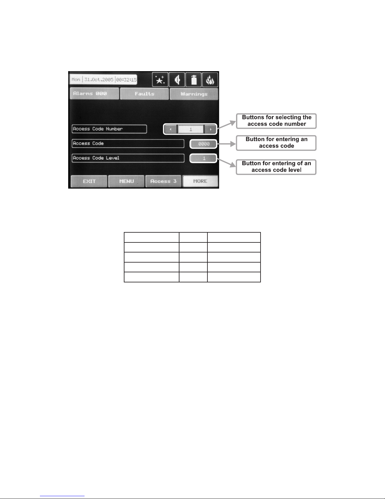
3.6 Access Codes
The access codes can be viewed and edited in the “ACCESS CODES” submenu, menu “Programming”
– see Fig. Screen 2 . It displays in turn: the code number, the access code (symbolic sequence) and the level
of access for the respective code – Fig. Screen 16. Other codes can be viewed by scrolling the navigation
arrows for changing the code number.
Fig. Screen 16.
By default the system has the following configuration of the access codes:
Code number Code Access Level
1 0000 1
2 1111 1
3 2222 2
4 3333 3
Accessible for programming are the fields “Code” and “Access level”. The “ACCESS CODES” menu is accessible only at access level 3.
3.6.1 Changing the Code
To change the access code select the “Button for introducing of access code” button on the right of the field
with the current code. The code introduction menu is automatically accessed. The code consists of 4 figures.
After the code is initially entered, the system shall request the code to be entered again for verification. If the
codes differ the system will ignore whatever was entered and the old code will remain active. If both codes
are identical, the new code will be displayed in the “ACCESS CODES” output field and an “Apply” button will
appear. Select “Apply” to save the entered code. If a code has already been entered the system will ignore it
and will retain the old one.
3.6.2 Changing the Access Level
Changing the level of access is done by choosing the “Change” button next to the field for calling out the access level. When activated a menu appears in which the user selects a new level of access (1-3) by pressing
the respective button or “EXIT” to leave. If the newly assigned access level is different from the current one,
the “Apply” button will be activated. Pressing that will save the new access level.
There must be at least one code in the system with an access code 3! The program disallows editing
a level of access (3) if it is the only one!
Page 33

Fire Panel IRIS - Installation Manual 33
4. MAINTENANCE
4.1 Maintenance Menu
To enter in the Maintenance Menu the installer has to choose button “Maintenance” – Fig. Screen 1. The
general view of the menu is shown on Fig. Screen 17.
Fig. Screen 17.
4.2 Time introducing
Choose the button “Time” from the Maintenance Menu to set the current time – Fig. Screen 18.
The desired time can be
set with the buttons for se
lecting the hours, minutes
and seconds.
Fig. Screen 18.
4.3 Date introducing
Choose the button “Date” from the Maintenance Menu to set the current date – Fig. Screen 19.
The desired date can be
set with the buttons for se
-
lecting the day, month and
year.
Fig. Screen 19.
Page 34
34 Fire Panel IRIS - Installation Manual
4.4 Daytime Mode
Choose the button “Day” from the Maintenance Menu to set the daytime schedule for detectors operation
– Fig. Screen 20.
Fig. Screen 20 Fig. Screen 21
In this mode the detectors use the alarm level which has been programmed as day mode. This is usually a
level of lower sensitivity. It lowers the risk of false alarms caused by dust, cigarette smoke, etc. Nighttime
mode is opposite to the daytime mode (higher level of sensitivity).
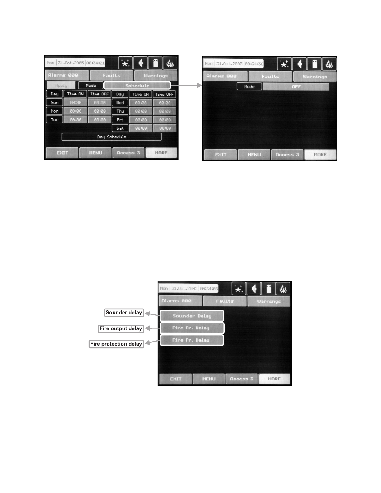
Daytime mode can be: ON, OFF or Schedule – Fig. Screen 21. In Schedule mode the initial hour and minutes
(the time when the daytime mode is activated) and the end hour and minutes (the time when the nighttime
mode is activated) are introduced. The times are set for every day of the week. By default the station is in
nighttime mode.
4.5 Output Delay Introduction
Choose the button “Output Delay” from the Maintenance Menu to set the output delay – Fig. Screen 22.
Fig. Screen 22
Page 35

Fire Panel IRIS - Installation Manual 35
4.5.1 Sounder Delay
Choose “Sounder Delay” button from “Output Delay” Menu – Fig. Screen 22 to enter the submenu for
sounder delay introduction – Fig. Screen 23.
A delay can be added before the sounders are turned on. This provides the possibility of checking the au
-
thenticity of the alarm before the sounders are turned on (an official visits the site of the fire and inspects for
such).
The delay can be: ON, OFF or Schedule – Fig. Screen 21. In Schedule mode the initial hour and minutes (the
time when the delay is activated) and the end hour and minutes (the time when the delay is deactivated) are
introduced. The times are set for every day of the week. During turned on “Delay” the LED is active.
Fig. Screen 23.
4.5.2 Fire output Delay
Choose “Fire Br. Delay” button from “Output Delay” Menu – Fig. Screen 22 to enter the submenu for fire
output delay introduction (the screen is the same as those for sounder delay introduction).
A delay can be added before the sounders are turned on (fire output). This provides the possibility of check
-
ing the authenticity of the alarm before the sounders are turned on (an official visits the site of the fire and
inspects for such).
The delay can be: ON, OFF or Schedule. In Schedule mode the initial hour and minutes (the time when the
delay is activated) and the end hour and minutes (the time when the delay is deactivated) are introduced. The
times are set for every day of the week. During turned on “Delay” the LED is active.
4.5.3 Fire Protection Delay
Choose “Fire Pr. Delay” button from “Output Delay” Menu – Fig. Screen 22 to enter the submenu for fire
protection delay introduction (the screen is the same as those for sounder delay introduction).
A delay can be added before the fire protection system is turned on. This provides the possibility of check
-
ing the authenticity of the alarm before the sounders are turned on (an official visits the site of the fire and
inspects for such).
The delay can be: ON, OFF or Schedule. In Schedule mode the initial hour and minutes (the time when the
delay is activated) and the end hour and minutes (the time when the delay is deactivated) are introduced. The
times are set for every day of the week. During turned on “Delay” the LED is active.
Page 36

36 Fire Panel IRIS - Installation Manual
4.6 LOG-file view
Choose “View Log” from the Maintenance Menu to enter in a screen for viewing the happened events in
the system. The addressable fire panel IRIS can show maximum 999 events, which could be viewed by
date or number – Fig. Screen 24.
Fig. Screen 24.
4.7 Testing
The addressable fire panel IRIS has an option for testing of zone functioning and the LED-indication of the
panel. To make a test, choose the “Test” button from Programming Menu – Fig. Screen 17. On the displayed
screen the user/installer could choose which test to perform – zone or LED-indication testing – Fig. Screen 25.
Fig. Screen 25.
After choosing the desired test by pressing the respective button, the user/installer could examine the proper
functioning of each zone and the LED-indication of the front panel. The entered information has to be confirmed by pressing “Apply” button.
Page 37

Fire Panel IRIS - Installation Manual 37
4.8 Disable introducing
The user/installer can enable or disable the loop devices, zones and the outputs of the fire panel. To introduce
enabling or disabling a function you can directly choose the respective button and make corrections, or first
by pressing “View” button to look at the current status of the system and after that, if it is necessary, to enter
new data – Fig. Screen 26.
Fig. Screen 26.
4.8.1 Loop Devices Disabling
The user/installer could first look at the current status of the loop devices by choosing “View” button situated
next to the “Loop devices” button – see Fig. Screen 26. On the screen of the panel is displayed the current
status of the loop devices programmed earlier in the system (see part Programming, §3.2.2 Loop Devices)
– Fig. Screen 27.
Fig. Screen 27
From the screen for the current status of the loop devices the user/installer can introduce new settings as
choose the button with the number of the respective device 1,2,3…40. With the buttons ▼▲ is possible to
be viewed and the other loop devices in the configuration of the system, with number over 40. By choosing a
button with a device number the user/installer moves to menu for setting of the parameters of the respective
device – see Fig. Screen 8, part Programming.
Note: From the disabling menu you can directly enter in the loop devices configuration menu (Fig.
Screen 8) as choose “Loop Devices” button (Fig. Screen 26).
Page 38

38 Fire Panel IRIS - Installation Manual
4.8.2 Zone disabling
The user/installer could first look at the current status of the loop devices by choosing “View” button situated
next to the “Zones” button – see Fig. Screen 26. On the screen of the panel is displayed the current status of
the loop devices programmed earlier in the system (see part Programming, §3.3 Zones) – Fig. Screen 28.
Fig. Screen 28
From the screen for the current status of the zones the user/installer can introduce new settings as choose
the button with the number of zone 1,2,3…50. With the buttons ▼▲ is possible to be viewed and the other
zones in the configuration of the system, with number over 50. By choosing a button with a zone number the
user/installer moves to menu for setting of the parameters of the respective zone – see Fig. Screen 12, part
Programming.
Note: From the disabling menu you can directly enter in the zone configuration menu (Fig. Screen 12)
as choose “Zones” button (Fig. Screen 26).
4.8.3 Outputs disabling
From the menu for disabling introduction – Fig. Screen 26, the user/installer can disable or enable the monitored outputs of the IRIS fire panel – Sounder, Fire Brigade, Fire Protection and Fire Routing – Fig. Screen 29.
Fig. Screen 29.
4.9 Software version
By choosing “Software Rev” button from the general Maintenance Menu, in a separate screen you can see
the last version of the used foftware.
Page 39

Fire Panel IRIS - Installation Manual 39
4.10 Calibrating the Display
It is possible that after a certain period of use the parameters of the Touchscreen display may change, causing difficulties in marking the sites. This would require it to be calibrated periodically, which can be done in
access levels 2 and 3.
ATTENTION! Calibrating the display must be done with a Touch screen pen (or PALM)!
To begin a display calibration procedure the following sequence of actions must be performed:
Main menu → Maintenance → Calibration → Coordinates
The calibration of the display runs in the following 4 stages – see also Fig. Screen 30.
1. The following message is displayed on the screen:
“Press the cross center in the top left corner of the screen:”
The user has to press the point on the top left corner of the display. It is marked with a cross and it is desir
-
able to choose the crossing point of the two lines. The calibration procedure shall continue after the point is
pressed.
2. The following message is displayed on the screen:
“Press the cross center in the top right corner of the screen:”
By analogy, the next point, which has to be pressed, is selected – in the top right corner of the display, once
again marked with a cross. The calibration procedure shall continue after the point is pressed.
3. The following message is displayed on the screen:
“Press the cross center in the botton right corner of the screen:”
This is the last point and is situated in the lower right corner of the display. The calibration procedure shall
continue after the point is pressed.
4. The following message is displayed on the screen:
“Press a point within the rectangle in the top left corner of the screen:”
This is the menu for verifying input data, and it is entered automatically. The user has to press the rectangular
field with the pen in the upper left corner of the display.
The message “Calibration Successful!!!” will be displayed if the calibration has been successful and after
pressing of any part of the display, the programme returns to the main menu.
The message “Calibration Unsuccessful!!!” will be displayed if the calibration has been unsuccessful, the
newly introduced data will be ignored and after pressing of any part of the display, the program returns to the
main menu.
Fig. Screen 30.
Page 40

40 Fire Panel IRIS - Installation Manual
5 INSTRUCTION FOR USE
5.1 Status Line
Purpose – Indicates the current status of the fire alarm panel, containing detailed information on the access
level, the working mode (day/ nighttime), the status of the fire output and fire protection, etc – see Fig. Screen
31 and Fig. Screen 32.
Fig. Screen 31.
5.1.1 Change of Access Level Button
Used for accessing the Change Access Level menu.
5.1.2 Button for Quick Access to Functional Buttons
Used for changing over from message review mode to functional buttons mode.
5.1.3 Alarm Access Mode
Used for accessing the alarm review window. The button contains a counter of the current alarms in the panel.
5.1.4 Error Access Button
Used for accessing the error review window.
5.1.5 Warning Access Button
Used for accessing the warnings review window.
Page 41

Fire Panel IRIS - Installation Manual 41
5.2 Panel Status Icons
Fig. Screen 32.
5.2.1 Panel Mode Icon
IDLE
LOADING – loads configuration data from permanent memory
SAVING – saves configuration data in permanent memory
DAY
– processes signals from detectors with enhanced sensitivity (set for every detector)
NIGHT
- processes signals from detectors with enhanced sensitivity (set for every detector)
5.2.2 Sounder Status Icon
ON (red) – activated output
OFF
(black) – dormant output
DISABLE
(grey) – deactivated output
DELAY
(red - blinks + countdown until activation) – delay is running prior to activation
(programmable for every zone)
5.2.3 Fire Output Status Icon
ON (red) – activated output
OFF
(black) – dormant output
DISABLE
(grey) – deactivated output
DELAY
(red - blinks + countdown until activation) – delay is running prior to activation
(programmable for every zone)
5.2.4 Fire Extinguishing Output Status Icon
ON (red) – activated output
OFF
(black) – dormant output
DISABLE
(grey) – deactivated output
DELAY
(red - blinks + countdown until activation) – delay is running prior to activation
(programmable for every zone)
Page 42

42 Fire Panel IRIS - Installation Manual
5.3 Messages
The maximal number of messages, which can be displayed is 3. The order in which they are displayed is:
1) first come;
2) all messages in between the first and the last, the scrolling is performed with the navigation buttons;
3) latest incoming message.
The messages displayed are abridged. To view the complete information it is necessary to pass into extended
image mode. This mode can be accessed by pressing on the respective message. Return to normal mode is
accomplished by pressing the “Exit” button.
5.4 Access
The control panel has 3 levels of access. The first level is accessible to users without having to introduce a
password. Levels 2 and 3 are accessible only after a password is introduced. The password is entered in the
change access level menu. At different access levels users have different restrictions to panel operations, as
shown in Table 1.
Function
Access
Level 1
Access
Level 2
Access
Level 3
Control
panel
Silence Buzzer
Silence Sounder
Delay Override
Reset
Evacuate
Alarms
Faults
SFaults
Warnings
Menu
Access Level
√
-
√
-
√
√
√
√
√
√
√
√
√
√
√
√
√
√
√
√
√
√
√
√
√
√
√
√
√
√
√
√
System
Disable
Test
Inputs/Outputs
Zone
Device
Configuration
Time
Calibration
View Log
Access Codes
Software
Revision
-
-
-
-
-
-
-
-
-
-
-
√
√
-
-
-
-
-
-
-
-
-
√
√
√
√
√
√
√
√
√
√
√
Table 1
Where the control panel is properly functioning, there should be no active messages in the various message
files. The green “Power ON” LED must remain lit.
In order to access the required access level (2 or 3), press “Access Level” once and than introduce the pass
-
word for the desired access level and confirm by pressing “OK” – Fig. Screen 33.
Page 43

Fire Panel IRIS - Installation Manual 43
Fig. Screen 33
4 digits need to be introduced. A short buzzer sound
acknowledges every pressing of the button. In the
interest of security, “*” will be displayed in the field in
tended for the password instead of the figures which
have been introduced. Use “Log Out” to exit access
level 1.
Fig. Screen 34
5.5 Silence Buzzer (1)
The “Silence Buzzer” button deactivates the internal buzzer.
5.6 Reset (2)
The “Reset” button is activated only in access levels 2 and 3. Where this button is pressed all activated statuses shall be overruled and the panel shall be brought to a normal state.
5.7 Delay Override (3)
The “Delay Override” button is activated only in access level 1. After it is pressed, all currently active output
delays shall be overruled.
5.8 Silence Alarm (4)
The “Silence Alarm” button is active only at access levels 2 and 3. Pressing this button will overrule all active
sounders and the associated thereto delays. In the case of an alarm present in the panel, pressing this button
would cause the “System Silenced” LED to be activated.
5.9 Evacuate (5)
The “Evacuate” button is activated only in access levels 2 and 3. After it is pressed, the sounder and the programmable outputs will be activated, the “General Fire” LED lights up and a warning message is displayed.
Page 44

44 Fire Panel IRIS - Installation Manual
5.10 Delay introducing
Fig. Screen 35
5.10.1 Zone Disabling
Fig. Screen 36
In the case of a disabled zone, the panel generates a “Zone Disabled” error message and the “Disable” and
“General Fault” LED-s on the control panel are activated. Any disabled zone will not generate messages to
the panel. (See also §4.5.1 Sounder delay, §4.5.2 Fire output delay and §4.5.3 Fire Protection delay form the
Installation instruction.)
Page 45

Fire Panel IRIS - Installation Manual 45
5.10.2 Loop devices disabling
Fig. Screen 37
In the case of a disabled device, the panel generates a “Device Disabled” error message and the “Disable”
and “General Fault” LED-s are activated. Any disabled device will not generate messages to the panel. In
the case of disabled devices associated with a given zone, where it has passed into Normal mode, and of all
devices without 1 if the zone is in “2Devices” mode, the same is automatically disabled and a “Zone Disabled”
error message is generated.
5.10.3 Outputs
Fig. Screen 38
In the case of disabled output, the panel generates an error for the respective output and the “Disable” and
“General Fault” LED-s are activated. The output is not activated by the activating event.
Page 46

46 Fire Panel IRIS - Installation Manual
6. APPENDIX
Appendix A
Possible error messages:
LOOP DEVICE TYPE ERROR
A different than the expected type of device has been detected
at the address.
LOOP DEVICE FAULT
The device does not respond (lost or damaged).
LOOP DEVICE DOUBLE ADDRESS
More than one device with the same address in the loop.
PREALARM Fire signal from detector in 2DEVICES zone.
EVACUATE Activated Call Point or EVACUATE button on the panel.
INPUT FAULT
Fault in loop device input.
OUTPUT FAULT
Fault in loop device output.
LOOP DEVICE DISABLED
Loop device has been disabled.
CHAMBER FAULT Fault in the detector.
CLEAN ME NOW Dirty detector chamber.
TEST FIRE Fire signal from tested detector.
SIGNAL BLOCKAGE Signal blockage in linear detector.
HI SIGNAL Too high a signal in linear detector.
EARTH FAULT
Resistive connection between some signals and earth < 10k.
BATTERY LOW Low battery.
CHARGER FAULT
Fault in the charging device.
BATTERY LOSS Loss of electric battery supply.
AC LOSS Loss of mains supply.
SOUNDER FAULT
Fault at sounder output (short-circuit or interruption).
FAULT ROUTING FAULT
Fault at problem output (short-circuit or interruption).
FIRE BRIGADE FAULT Fault at fire output (short-circuit or interruption).
FIRE PROTECTION FAULT
Fire protection fault (short-circuit or interruption).
AUX24V FAULT
Short-circuit.
AUX12V FAULT
Short-circuit.
PERIPHERY DEVICE FAULT
The device does not respond (lost or damaged).
PERIPHERY DEVICE TYPE ERROR A different than the expected type of device has been detected
at the address.
EXTERNAL POWER SUPPLY FAULT
External power supply fault (low battery, loss of battery,
charger fault, loss of mains or earth leak).
EXTERNAL POWER SUPPLY LOSS Loss of external power supply.
ZONE DISABLED The zone has been disabled.
TEST ZONE
The zone is in test mode.
SOUNDER DISABLED The sounders have been disabled.
FIRE BRIGADE DISABLED The fire output has been disabled.
FIRE PROTECTION DISABLED The fire protection has been disabled.
FAULT DISABLED
The fault output has been disabled.
PERIPHERY DEVICE NEW
New periphery devices have been detected.
LOOP DEVICE NEW
New loop devices have been detected.
LOOP SHORT
Short-circuit in the loop.
LOOP BREAK
Interrupted loop.
ALARM Fire signal from detector.
Page 47

Fire Panel IRIS - Installation Manual 47
Appendix B
Tables for correspondence of the device types.
Devices with no need of type
readjustment.
Detection of
the panel.
LED switching on -
ON (BLINK)
2
Maintenance of
day and night
time working
modes
3
.
Day / night time
confirmation of
an alarm signal
4
.
- 2251EIS (Photoelectric smoke sensor) - 2251EM in case of a FIRE signal √ √
- 6200 (Smoke beam sensor) - 2251EM in case of a FIRE signal √ √
- FTX-P1 (Photoelectric smoke sensor) - 2251EM in case of a FIRE signal √ √
- 6500 (Linear smoke sensor)
1
- 2251EM in case of a FIRE signal √ √
- 5251REM (Temperature sensor)
- 5251EM in case of a FIRE signal √ √
- 5251HTEM (Temperature sensor)
- 5251EM in case of a FIRE signal √ √
- M220E (Dual input) - M210E in case of activation at the input - -
- M221EINPUT (Input)
- M210E in case of activation at the input - -
- M221EOUTPUT (Output)
- M201E in case of activation at the output - -
- M201E - 240 (Main switch output) - M201E in case of activation at the output - -
- M501ME (Input) - M210E in case of activation at the input - -
- M503ME (Micro monitor) - M210E in case of activation at the input - -
- M500KAC (Call point) - M210E in case of activation at the input - -
- EMA24 (Loop sounder) - M201E in case of activation at the input - -
- DBS24 (Loop sounder) - M201E in case of activation at the input - -
1
The device can be tested by covering the reflector, depending on the selected alarm level. As a result a FIRE signal is generated to the respective zone. In the case of
complete blockage of the reflector a “BEAM BLOCKAGE” message is generated. If there are any reflective objects in the path of the detector a “SIGNAL OVER RANGE”
message is generated.
2
A specific mode is assigned to the light-emitting diode of the device: BLINK and OFF. In the BLINK mode the LED blinks at every query addressed by the system. In the OFF
mode the LED does not reflect any device contact. The LED turns ON in case of a FIRE signal.
3
The device maintains day and night time working modes. Each of these are assigned different times of filtration of the FIRE signal. The night time mode must be less than
that of the daytime mode. For specific cases the times of both modes can be 0, disallowing filtration time, having the fire signal is immediately perceived.
4
The devices maintains day and night confirmation of alarm (in seconds). The alarm must remain active during the programmable period of time in order to generate an alarm
event from the panel. If the detector restores its normal state prior to time-out, the panel shall not generate the alarm.
Page 48

48 Fire Panel IRIS - Installation Manual
Tables for correspondence of the device types.
Devices where there is need of type
readjustment.
LED switching on -
ON (BLINK)
1
Maintenance of
day and night time
working modes.
Thresholds
for the FIRE
signal
2
Day / night time for an
alarm confirmation
3
- 1251E (Ionisation sensor) in case of a FIRE signal √ (1-3) √
- 2251EM (Photoelectric smoke sensor) in case of a FIRE signal √ (1-3) √
- 5251EM (Temperature sensor) in case of a FIRE signal √ - √
- 2251TEM (Multi-criteria fire sensor)
in case of a FIRE signal √ (1-6) √
- 7251 (Photoelectric smoke sensor) in case of a FIRE signal √ (1-9) √
- M210E (Single input) in case of activation at the input - - -
- M201E (Single output) in case of activation at the output - - -
- M512ME (Zone monitor) in case of activation at the input - - -
1
A specific mode is assigned to the light-emitting diode of the device: BLINK and OFF. In the BLINK mode the LED blinks at every query addressed by the system. In the OFF
mode the LED does not reflect any device contact. The LED turns ON in case of a FIRE signal.
2
The device maintains day and nighttime working modes. Each of these are assigned different times of filtration of the FIRE signal. The night time mode must be less than
that of the daytime mode. For specific cases the times of both modes can be 0, disallowing filtration time, having the fire signal is immediately perceived.
3
The devices maintains day and night confirmation of alarm (in seconds). The alarm must remain active during the programmable period of time in order to generate an alarm
event from the panel. If the detector restores its normal state prior to time-out, the panel shall not generate the alarm.
Page 49

Fire Panel IRIS - Installation Manual 49
INDEX
Gurantee .................................................................................................................................................... 2
1. INTRODUCTION .................................................................................................................................... 3
1.1 General description ............................................................................................................................ 3
1.2 General specifications ....................................................................................................................... 3
1.2.1 General Technical Specifications .................................................................................................. 4
1.2.2 Structure .......................................................................................................................................... 4
1.2.3 Environment .................................................................................................................................... 4
1.2.4 Electrical Specifications ................................................................................................................. 4
2. INSTALLATION ...................................................................................................................................... 6
2.1 Mounting ............................................................................................................................................. 6
2.1.1 Wall Mounting .................................................................................................................................. 6
2.1.2 Flush Mounting ................................................................................................................................ 7
2.2 System Components .......................................................................................................................... 8
2.2.1 Front panel ....................................................................................................................................... 8
2.2.2 Confuguration of the basic modules ............................................................................................. 8
2.2.3 Main Board ....................................................................................................................................... 9
2.2.4 20 Relay Expander Module ............................................................................................................. 11
2.2.5 Loop Expander ................................................................................................................................ 12
2.2.6 Maximum permissible cable lenght ............................................................................................... 13
2.2.7 Main Power Source ......................................................................................................................... 14
2.2.8 Connecting of the accumulator battery......................................................................................... 15
2.3 Network connection diagram ............................................................................................................ 16
3. Programming ........................................................................................................................................ 17
3.1 Programming Menu ............................................................................................................................ 17
3.2 Devices ................................................................................................................................................ 18
3.2.1 Periphery devices ............................................................................................................................ 18
3.2.1.1 Phisical Address of Periphery Device ........................................................................................ 19
3.2.1.2 Button for entering the device submenu ................................................................................... 19
3.2.1.3 Current status of the device ........................................................................................................ 20
3.2.2 Loop devices ................................................................................................................................... 20
3.2.2.1 Confirm change button................................................................................................................ 21
3.2.2.2 Button to enable / disable a device ............................................................................................ 21
3.2.2.3 Module or detector selection button .......................................................................................... 21
3.2.2.4 Address navigation button .......................................................................................................... 21
3.2.2.5 Loop number navigation button ................................................................................................. 21
3.2.2.6 Zone selection button .................................................................................................................. 21
3.2.2.7 Current device status ................................................................................................................... 21
3.2.2.8 Button for changing the current status of the device ............................................................... 21
3.2.2.9 Change device type button ......................................................................................................... 21
3.2.2.10 Active field for text introducing ................................................................................................ 22
3.2.2.11 Additional settings buttons ....................................................................................................... 22
3.2.2.12 Maintaned loop devices ............................................................................................................. 23
3.2.2.12.1 1251E (Ionization sensor) ....................................................................................................... 23
3.2.2.12.2 2251EM (Photoelectric smoke sensor) .................................................................................. 23
3.2.2.12.3 2251EIS (Photoelectric smoke sensor) ................................................................................. 23
3.2.2.12.4 6200 (Smoke beam sensor) .................................................................................................... 24
3.2.2.12.5 FTX-P1 (Photoelectric smoke sensor) ................................................................................... 24
3.2.2.12.6 6500 (Linear smoke sensor) ................................................................................................... 24
3.2.2.12.7 5251EM (Temperature sensor) ............................................................................................... 24
3.2.2.12.8 5251REM (Temperature sensor) ............................................................................................. 25
3.2.2.12.9 5251HTEM (Temperature sensor) ........................................................................................... 25
3.2.2.12.10 2251TEM (Multi-criteria fire sensor) .................................................................................... 25
3.2.2.12.11 7251 (Photoelectric smoke sensor) ..................................................................................... 25
3.2.2.12.12 M210E (Single input) ............................................................................................................. 26
3.2.2.12.13 M220E (Dual input) ................................................................................................................ 26
3.2.2.12.14 M221EINPUT (Input) .............................................................................................................. 26
Page 50

50 Fire Panel IRIS - Installation Manual
3.2.2.12.15 M221EOUTPUT (Output) ....................................................................................................... 26
3.2.2.12.16 M201E - 240 (Main switch output) ........................................................................................ 26
3.2.2.12.17 M501ME (Input) ...................................................................................................................... 26
3.2.2.12.18 M503ME (Micro monitor) ....................................................................................................... 27
3.2.2.12.19 M500KAC (Call point) ............................................................................................................ 27
3.2.2.12.20 M512ME (Zone monitor) ........................................................................................................ 27
3.2.2.12.21 EMA24 & DBS24 (Loop sounder) ......................................................................................... 27
3.3 Zones ................................................................................................................................................... 28
3.3.1 Buttonts for selecting the zone number ........................................................................................ 28
3.3.2 Active field for Introducing zone number ..................................................................................... 28
3.3.3 Button for zone mode changing .................................................................................................... 28
3.3.4 Sounder delay .................................................................................................................................. 28
3.3.5 Fire output delay ............................................................................................................................. 28
3.3.6 Fire protection output delay ........................................................................................................... 28
3.3.6 Enable / Disable zone button.......................................................................................................... 28
3.4 Inputs ................................................................................................................................................... 29
3.4.1 Input delay ....................................................................................................................................... 29
3.4.2 Input active status (Polarity) .......................................................................................................... 29
3.4.3 Mode ................................................................................................................................................. 29
3.4.4 Input type selection menu .............................................................................................................. 29
3.4.5 Input parameters selection menu .................................................................................................. 29
3.5 Outputs ................................................................................................................................................ 30
3.5.1 Output type selection menu ........................................................................................................... 31
3.5.2 Output parameters selection menu ............................................................................................... 31
3.5.3 Output delay .................................................................................................................................... 31
3.5.4 Output active status (Polarity) ....................................................................................................... 31
3.5.5 Output pulse type ............................................................................................................................ 31
3.5.6 Input selection menu ...................................................................................................................... 31
3.5.7 Mode ................................................................................................................................................. 31
3.6 Access codes ...................................................................................................................................... 32
3.6.1 Changing the code .......................................................................................................................... 32
3.6.2 Changing the access level ............................................................................................................. 32
4. Maintenance .......................................................................................................................................... 33
4.1 Maintenance menu ............................................................................................................................. 33
4.2 Time setting ........................................................................................................................................ 33
4.3 Date setting ......................................................................................................................................... 33
4.4 Daytime mode ..................................................................................................................................... 34
4.5 Outputs delay introducing ................................................................................................................. 34
4.5.1 Sounder delay .................................................................................................................................. 35
4.5.2 Fire output delay ............................................................................................................................. 35
4.5.3 Fire protection output delay ........................................................................................................... 35
4.5 LOG-file viewing ................................................................................................................................. 36
4.7 Testing ................................................................................................................................................. 36
4.8 Disabling ............................................................................................................................................. 37
4.8.1 Loop devices disabling ................................................................................................................... 37
4.8.2 Zone disabling ................................................................................................................................. 38
4.8.3 Output disabling .............................................................................................................................. 38
4.9 Software version ................................................................................................................................ 38
4.10 Display callibration .......................................................................................................................... 39
5. Instruction for use ................................................................................................................................ 40
5.1 Statuse line ......................................................................................................................................... 40
5.1.1 Change of access livel button ........................................................................................................ 40
5.1.2 Quick access to the functional buttons ........................................................................................ 40
5.1.3 Alarm access button ....................................................................................................................... 40
5.1.4 Fault access button ......................................................................................................................... 40
5.1.5 Warnings access button ................................................................................................................. 40
5.2 Icons for the panel status .................................................................................................................. 41
5.2.1 Panel mode icon .............................................................................................................................. 41
Page 51

Fire Panel IRIS - Installation Manual 51
5.2.2 Sounder status icon ........................................................................................................................ 41
5.2.3 Fire output status icon .................................................................................................................... 41
5.2.4 Fire protection output status .......................................................................................................... 41
5.3 Messages ............................................................................................................................................ 42
5.4 Access ................................................................................................................................................. 42
5.5 Silence Buzzer button ........................................................................................................................ 43
5.6 Reset button ........................................................................................................................................ 43
5.7 Delay override button ........................................................................................................................ 43
5.8 Silence alarm button .......................................................................................................................... 43
5.9 Evacuate button ................................................................................................................................. 43
5.10 Disabling ........................................................................................................................................... 44
5.10.1 Zone disabling ............................................................................................................................... 44
5.10.2 Loop devices disabling ................................................................................................................. 45
5.10.3 Outputs disabling .......................................................................................................................... 45
Appendix A ................................................................................................................................................ 46
Appendix B ................................................................................................................................................ 47
Page 52

18020446 Рев. A / Rev. A 07/2006
 Loading...