

Page 1

INSTALLATION
MANUAL
ECLIPSE 8
(S.W. 1.87)
ECLIPSE 32
(S.W. 1.87)
ALARM CONTROL PANELS
Attention:
This manual contains information on limitations regarding product use and
function and information on the limitations as to liability of the manufacturer.
The entire manual should be carefully read.
The information in this manual is a subject to change without notice!
Page 2

Eclipse 8/ 32 Series - Installation Manual
2
Table of Contents:
QUICK STEPS OF INSTALLATION .................................................................................................................................. 4
1. GENERAL INFORMATION ........................................................................................................................................... 6
2. INSTALLATION ............................................................................................................................................................. 7
2.1. Control Panels Mounting ............................................................................................................................... 7
2.1.1 ECLIPSE 8 ....................................................................................................................................... 7
2.1.2 ECLIPSE 32 ..................................................................................................................................... 8
2.2. Control Panels PCB Layouts ......................................................................................................................... 9
2.2.1 ECLIPSE 8 ....................................................................................................................................... 9
2.2.2 ECLIPSE 32 ................................................................................................................................... 10
2.3. Zone Connection ......................................................................................................................................... 11
2.3.1 Connection Style Diagrams ........................................................................................................... 11
2.3.2 Connecting shutter detector to a zone (for ECLIPSE 32) .............................................................. 13
2.3.3 Checking the line resistance .......................................................................................................... 13
2.3.4 Connecting Fire Lines .................................................................................................................... 14
2.4. Connection of Peripheral Devices ............................................................................................................... 15
2.4.1 Connection to the System Bus ...................................................................................................... 15
2.4.2 Supported Keyboards .................................................................................................................... 16
2.4.3 Supported Expander modules ....................................................................................................... 18
2.4.4 Supported Proximity Card Readers ............................................................................................... 20
2.5. Connection of PGM Outputs ....................................................................................................................... 21
2.6. Connection of Siren to PGM5 Output.......................................................................................................... 22
2.7. Connecting the Digital Communicator......................................................................................................... 23
2.8. ECLIPSE VD Voice Dialer ........................................................................................................................... 23
2.9. Connecting Communication Modules ......................................................................................................... 24
3. INITIAL POWER-UP and RESET ALGORITHMS ....................................................................................................... 24
3.1. Initial Power-up algorithm ............................................................................................................................ 24
3.2. Reset Algorithm ........................................................................................................................................... 24
4. TROUBLE EVENTS .................................................................................................................................................... 25
5. ENROLLING / DELETING OF DEVICES .................................................................................................................... 25
5.1. Enrolling Devices during the Initial Power-up of the Control Panel ............................................................ 25
5.2. Enrolling Devices to a working system configuration via LCD keyboard .................................................... 25
5.3. Enrolling Devices to a working system configuration via LED keyboard .................................................... 26
5.4. Deleting of a device from the system configuration .................................................................................... 27
6. OPERATION WITH A SERVICE KEYBOARD ......................................................................................................... 27
Page 3

Eclipse 8/ 32 Series - Installation Manual
3
GUARANTEE
The guarantee terms are determined by the serial number (barcode) of the electronic device!
During the guarantee period the manufacturer shall, at its sole discretion, replace or repair any defective product when it is returned to the factory. All
parts replaced and/or repaired shall be covered for the remainder of the original guarantee, or 6 months, whichever period is longer. The original
purchaser shall immediately send manufacturer a written notice of the defective parts or workmanship.
INTERNATIONAL GUARANTEE
Foreign customers shall possess the same guarantee rights as those any customer in Bulgaria, except that manufacturer shall not be liable for any
related customs duties, taxes or VAT, which may be payable.
GUARANTEE PROCEDURE
The guarantee will be granted when the appliance in question is returned. The guarantee period and the period for repair are determined in advance.
The manufacturer shall not accept any product, of which no prior notice has been received via the RAN form at: http://www.teletek-
electronics.com/en/support/Service
The setup and programming included in the technical documentation shall not be regarded as defects. Teletek Electronics bears no responsibility for
the loss of programming information in the device being serviced.
CONDITIONS FOR WAIVING THE GUARANTEE
This guarantee shall apply to defects in products resulting only from improper materials or workmanship, related to its normal use. It shall not cover:
Devices with destroyed serial number (barcode);
Damages resulting from improper transportation and handling;
Damages caused by natural calamities, such as fire, floods, storms, earthquakes or lightning;
Damages caused by incorrect voltage, accidental breakage or water; beyond the control of the manufacturer;
Damages caused by unauthorized system incorporation, changes, modifications or surrounding objects;
Damages caused by peripheral appliances unless such peripheral appliances have been supplied by the manufacturer;
Defects caused by inappropriate surrounding of installed products;
Damages caused by failure to use the product for its normal purpose;
Damages caused by improper maintenance;
Damages resulting from any other cause, bad maintenance or product misuse.
In the case of a reasonable number of unsuccessful attempts to repair the product, covered by this guarantee, the manufacturer’s liability shall be
limited to the replacement of the product as sole compensation for breach of the guarantee. Under no circumstances shall the manufacturer be liable
for any special, accidental or consequential damages, on the grounds of breach of guarantee, breach of agreement, negligence, or any other legal
notion.
WAIVER
This Guarantee shall contain the entire guarantee and shall be prevailing over any and all other guarantees, explicit or implicit (including any implicit
guarantees on behalf of the dealer, or adaptability to specific purposes), and over any other responsibilities or liabilities on behalf of the
manufacturer. The manufacturer does neither agree, nor empower, any person, acting on his own behalf, to modify, service or alter this Guarantee,
nor to replace it with another guarantee, or another liability with regard to this product.
UNWARRANTED SERVICES
The manufacturer shall repair or replace unwarranted products, which have been returned to its factory, at its sole discretion under the conditions
below. The manufacturer shall accept no products for which no prior notice has been received via the RAN form at: http://www.teletek-
electronics.com/en/support/Service .
The products, which the manufacturer deems repairable, will be repaired and returned. The manufacturer has prepared a price list and those
products, which can be repaired, shall be paid for by the Customer. The devices with unwarranted services carry 6 month guarantee for the replaced
parts.
The closest equivalent product, available at the time, shall replace the products, the manufacturer deems un-repairable. The current market price
shall be charged for every replaced product.
STANDARDS AND CONFORMITY
The Eclipse Series control panels are designed according and with conformity to the European Union (EU) Low Voltage Directive (LVD) 2006/95/EC
and Electro-Magnetic Compatibility (EMC) Directive 2004/108/EC.
The CE mark is placed for indication that the Eclipse Series control panels comply with the requirement of EU for safety, health, environmental and
customer protection.
The Eclipse Series control panels are suitable for installation and operation in security systems specially designed to comply with standard EN
50131-1, grade 2.
Page 4

Eclipse 8/ 32 Series - Installation Manual
4
QUICK STEPS OF INSTALLATION
Step 1 Working plan-diagram of the system
Draw out a working plan diagram of the site and locate the elements of the alarm control system on it. Choose the best
place for installation of the detectors, control keyboards and other system devices.
Step 2 Installation of the control panel
Choose a place for installation of the control panel close to mains power 220V and telephone line terminals. Choose
the most appropriate openings for running the power supply cable, zone wires, PGM outputs and the system BUS.
Mount the bottom of the box on the wall as use the supplied on the back side of the package template for drilling.
Mount a tamper-switch and level it according the installation surface to provide the box self-protection. Connect the
wires of the tamper-switch to that zone considered to be TAMPER type.
ATTENTION: The initial power-up of the panel is only after completing all the wiring of the system!
Step 3 Connecting devices to the system BUS
Connect all keyboards and expander modules to the control panel using 4-wire alarm cable (system BUS). It is
obligatory to follow the correspondence of the colors between control panel and keyboard/ additional devices terminals.
Use the detailed connection diagrams provided in item 2.4 of this manual.
Step 4 Connecting of zones
Connect the detectors in the zones as use one of the following connection diagrams according the respective
application. According your system you can choose among different connection styles diagrams:
ECLIPSE 8 – 5 connection styles diagrams for single zone connection
ECLIPSE 32 – 9 connection diagram styles for single and doubling zone connection
Use the detailed connection diagrams provided in item 2.3 of this manual.
Step 5 Connecting of sirens, PGM outputs and other devices
Connect the sirens, controlling devices (such as proximity card readers or remote controls), the digital communicator,
communicator modules, etc. Use the detailed connection diagrams provided in items 2.5-8 of this manual.
Step 6 Initial power-up of the control panel
1. Set a jumper to RESET terminal of the main control panel Eclipse (see the general connection diagram).
2. Power the control panel from the mains 220V.
3. Connect the battery wires to accumulator battery 12V/7Ah for back-up power supply as strictly observe the polarity:
red wire to “+” battery terminal, black wire to “-”.
4. The backlights of all connected to the system BUS control keyboards light up and a procedure for
Initial initialization starts running. Wait for 15-20 sec until ending of initialization procedure. Now the system is ready for
registration of devices.
5. Press the ENT () button of all connected to the system BUS keyboards one-by-one – this is the way to register the
keyboards to the control panel. Press the little button (located between the two terminal rows) of all expanding modules
connected to the system BUS to register them to the control panel. A confirmation sound signal is heard – see also the
other ways for registration of devices to the control panel described in item 5.
ATTENTION: DO NOT press the PRG button of any of the keyboards during the registration procedure. Otherwise,
you will register the keyboard as “Service keyboard”!
6. Remove the jumper from RESET terminal.
7. Wait until the system BUS LED stops blinking in green.
Page 5

Eclipse 8/ 32 Series - Installation Manual
5
Step 7 Programming the system
1. The default programming style is the one using text tree-structure for the engineer menus (LCD keyboard). To
change the programming style at the beginning you have to enter first the engineer menu with valid code (7777 by
default) and choose in sequence:
7777 – 2.SETTINGS – 14. MENU STYLE: TEXT, ADDRESS or OPERATION
. Confirm with ENTER ().
2. Program the general zone parameters:
- Connecting type (address 2000, operation 200). Enter the number of the chosen connection diagram - see
Step 4.
- Pulse count (address 2003, operation 203).
- Zone types and their distribution in the used areas, etc. You can use the cloning function to set the
parameters of one zone to other zones (address 2005, operation 205).
3. Program the parameters of the PGM outputs, time slots, areas and users in the system – for details see the
Programming tables in the ECLIPSE 8/ 32 Series - Engineer Programming Manual.
Note: If the PGM5 output is not used for connecting siren you must program it as PGM with general application – at
address 3051, option 1 is off.
Step 8 Testing system
Test the system for correct functioning and operating efficiency according the programmed parameters. Test arming
and disarming with the keyboards, readers and remote controls. Test the activation of the siren and the digital
communicator after an alarm event.
Step 9 Archiving the system parameters and configuration
If possible make an archive for the system elements, programming parameters and configuration. Save a system
configuration (as .TDF file) with ProsTE software to make a data base of the installed system in the site.
Step 10 Training the users to operate and manage the system
As a last step make a short training with the users of the system to familiarize with the basic functions and operations
with the system:
1. Arming and disarming the system using keyboard or proximity card reader.
2. Zone bypassing in the site – why and how to do.
3. Changing own user code.
4. Review of system events and troubles.
5. Basic functions of the buttons and indication on the display.
6. Make also more detailed training of the system managers to operate and program the system with the
extended Manager Programming menus.
Page 6
Eclipse 8/ 32 Series - Installation Manual
6
1. GENERAL INFORMATION
The ECLIPSE series Alarm control panels are designed and tested in compliance with electromagnetic compatibility
(EMC) standards. The ECLIPSE 32 alarm control panel covers the requirements of GRADE 2.
The following recommendations need to be observed for the proper performance of the alarm station:
Ensure the alarm system is properly earthed (grounded).
Insulate the high and low voltage cables and use different input openings on the box.
Avoid any loops of connecting wires within the very box and in their passage over or under the printed circuit
boarding.
Additional relays MUST NOT be placed in the Eclipse 8/32 Alarm control panel box as these may generate
electromagnetic interference when switched.
- Use only relays with good insulation between contacts and the winding.
- Relays, connected to outputs with an open commutator, must be designed to accommodate a 12 V DC
driving voltage and an impedance at the winding greater than 400Ω.
The cable connecting the control panel and the keyboard is quadruple.
It is strongly recommended not to: use this cable to make other connections - connect to a telephone line, Flashlamps control signals, sirens or relays.
Avoid channels or cable forms that contain high voltage cables when placing the connecting shielded cables. This
is very important in cases where such cables are being used to power electric motors, fluorescent lamps or triplephase voltage. Where the above is not possible, use only shielded cables, where the shield is grounded only in the
alarm system box.
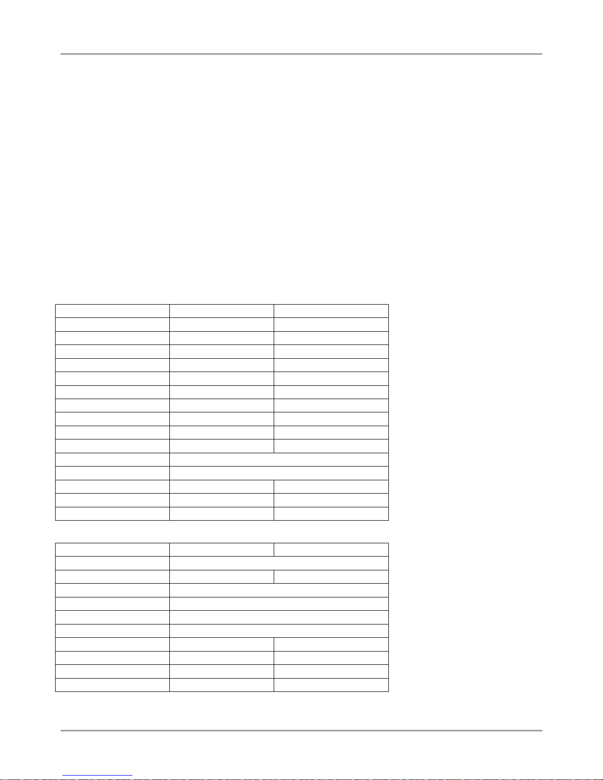
Technical Features:
Feature
ECLIPSE 8
ECLIPSE 32
Zones (on board)
6
8
Max. Zones (expanded)
8
32
Areas
1
8
4 x 100mA Outputs
1 x 1A Monitored Output
-
Max. Outputs (expanded)
5
32
User Codes 8 64
Schedules
-
LOG Events
256
1024
BUS Devices 2 31
Programming
Address, Operation, Text menus; ProsTE software
Arming modes
Full, Stay, Sleep
Digital communicator
(2 tel. numbers)
(4 tel. numbers)
Voice Dialer (option)
(8 tel. numbers)
(8 tel. numbers)
Remote programming
-
Technical Specifications:
Specification
ECLIPSE 8
ECLIPSE 32
Mains Power Supply
230 VAC ±10%, fuse 0.63A
Mains Transformer
17 VAC / 17 VA
15-26 VAC / 50 VA
Back-up Power Supply
1 x Accumulator 12 V / 7 Ah
Accumulator charger
13.8V, resettable fuse 0.75А
Consumption
100 mA (for control panel)
Enclosure
ABS plastic box, white
Dimensions, mm
290 x 240 x 80
335 x 290 x 105
Operation temperature
from -10°C to +60°C
from 0°C to 50°C
Relative humidity
95%
95%
Weight, kg
1.40
2.30
Page 7

Eclipse 8/ 32 Series - Installation Manual
7
2. INSTALLATION
2.1. Control Panels Mounting
The ECLIPSE series alarm control panels are available in plastic box for wall mounting. There is additional space for
mounting of communication and expander modules in the box.
2.1.1 ECLIPSE 8
ECLIPSE 8 Alarm Control Panel is mounted in a white plastic box with dimensions 290 x 240 x 80mm. There is
additional space for mounting of one communication module in the box. For the back-up battery is provided special
place. The box is equipped also with a transformer unit and 220V connection terminal with protective fuse.
The front cover is fixed with two mounting screws provided in the spare parts kit. Before the installation, break out the
protective caps for the front panel from the bottom box – see the picture below. After fixing the front panel with the
screws put also the protective caps on their places.
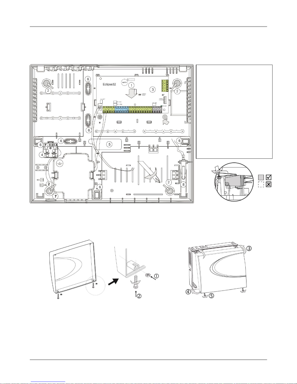
Figure 1. ECLIPSE 8 box elements
Figure 2. ECLIPSE 8 final closing
- General support opening of the
box (situated under the PCB);
- Support openings;
- ECLIPSE 8 control panel;
- Mains power supply terminal with
fuse 0.63A;
- Main cable opening;
- Plastic cap for fixing the mains
power cable;
- Plastic caps for front panel;
- Place for mounting of tamper-
switch (the tamper-switch is not
included in the supplied equipment).
In ECLIPSE 8 final closing, use the supplied
screws in the spare parts kit to fix the front cover
to the mounted bottom.
Use the plastic caps (position at Figure 1)
previously broken out from the box bottom to hide
the screw heads at final closing.
Transformer unit
50-60 Hz
17V/ 17VA
Place for mounting of
additional modules
Place for mounting a back-up
batter 12V/ 7Ah
Page 8
Eclipse 8/ 32 Series - Installation Manual
8
2.1.2 ECLIPSE 32
ECLIPSE 32 Alarm Control Panel is mounted in a white plastic box with dimensions 335 x 290 x 105mm. There are
additional spaces for mounting of one communication module in the box and one expander module (under the main
PCB). For the back-up battery is provided special place. The box is equipped also with a transformer unit and 220V
connection terminal with protective fuse.
The front cover is fixed with two mounting screws and nuts provided in the spare parts kit.
Figure 3. ECLIPSE 32 box elements
In ECLIPSE 32 final closing, use the supplied screws and nuts in the spare parts kit to fix the front cover to the
mounted bottom.
- Put the nuts into the nests on the backside of the front cover;
- Take the screws with interrupted thread and screw on them into the openings at the front cover bottom
until the nut and the interrupted part come together.
- Fix the front cover onto the mounted bottom;
- Close the cover;
- Screw on the screw for final closing.
Figure 4. ECLIPSE 32 final closing
- General support opening of
the box (situated under the PCB);
- Support openings;
- ECLIPSE 32 control panel;
- Mains power supply terminal
with fuse 0.63A;
- Main cable opening;
- Additional cable openings;
Remove the plastic caps from the
box bottom and fix the cable with
them;
- Mains power supply opening;
- Place for mounting of tamper-
switch (the tamper-switch is not
included in the supplied
equipment).
Tamper
regulation
Place for
mounting of
additional
modules
Place for mounting of additional modules
Transformer unit
15-25V/ 50VA
Place for back-up battery
12V/ 7Ah
Page 9
Eclipse 8/ 32 Series - Installation Manual
9
2.2. Control Panels PCB Layouts
2.2.1 ECLIPSE 8
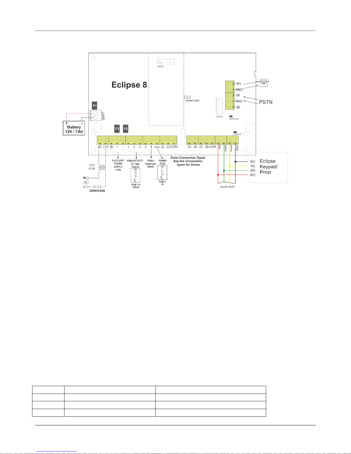
Figure 5. ECLIPSE 8 control panel
ECLIPSE 8 - Terminals and components:
17VAC – Power supply from a mains transformer 17V / 17VA, fuse 0.63А
GND – Common ground
+/- AUX – Power supply for detectors with consumption up to 0.75А
+PGM – Power supply of auxiliary devices with consumption up to 0.75А
PGM 1-3 – Programmable outputs, 100mA, ОС type (open collector)
PGM 4 – Programmable output / Serial link, 100mA, ОС type (open collector)
PGM 5/SIREN – Programmable output, high power up to 1А, ОС type (open collector), for connecting siren
Z1-Z6 – Zone inputs
COM – Common ground
RED, GRN, YEL, BLK - System bus interface for connection of keyboards, proximity card readers, expanders, etc.
Jumper RESET – Jumper for total hardware reset of the control panel
Serial – PC Interface connection
VOICE - Interface connector for mounting of Voice module ECLIPSE VD
BATT – Terminals for connecting the back-up battery
PSTN terminals:
TIP1, RING1 – Connect the telephone
TIP, RING – Connect the PSTN line
GND – Common ground
Fuses, PTC type:
F1 – Fuse for the back-up battery: 0,75A
F2 – Fuse for PGM outputs: 0.5A
F3 – Fuse for AUX outputs: 0.5A
LED indication:
PSTN – LED for the status of the built-in digital communicator.
BUS LED – LED for the status of the system bus:
BUS LED
Lights on permanently
Blinks in pulses
Red
RESET Jumper is set
Low power supply
Yellow
Short circuit of the system bus
Wrong connection of the system bus
Green
Selected device of the system bus
Normal operation mode
Page 10

Eclipse 8/ 32 Series - Installation Manual
10
2.2.2 ECLIPSE 32
Figure 6. ECLIPSE 32 control panel
ECLIPSE 32 - Terminals and components:
17VAC – Power supply from a mains transformer 15-25V / 50VA, fuse 0.63А
GND – Common ground
+/- AUX – Power supply for detectors with consumption up to 0.75А
+PGM – Power supply of auxiliary devices with consumption up to 0.75А
PGM 1-3 – Programmable outputs, 100mA, ОС type (open collector)
PGM 4 – Programmable output / Fire zone (programmed at Menu 3. Programmable outputs), 100mA, ОС type (open
collector)
PGM 5/BELL – Programmable output, high power up to 1А, ОС type (open collector), for connecting siren
Z1-Z8 – Zone inputs
COM – Common ground
RED, GRN, YEL, BLK - System bus interface for connection of keyboards, proximity card readers, expanders, etc.
Jumper RESET – Jumper for total hardware reset of the control panel
Interface Connector – Interface for PC connection
VOICE - Interface connector for mounting of Voice module ECLIPSE VD
BATT – Terminals for connecting the back-up battery
BATT 1 - Battery CR-2032 3V, 120-150mAh (factory mounted on the back of the control panel)
PSTN terminals:
TIP1, RING1 – Connect the telephone
TIP, RING – Connect the PSTN line
GND – Common ground
Fuses, PTC type:
F1 – Fuse for the back-up battery: 2.5A
F2 – Fuse for PGM outputs: 0.75A
F3 – Fuse for AUX outputs: 0.75A
F4 – Fuse for the system bus: 0.5А
LED indication:
PSTN – LED for the status of the built-in digital communicator.
BUS LED – LED for the status of the system bus:
BUS LED
Lights on permanently
Blinks in pulses
Red
RESET Jumper is set
Low power supply
Yellow
Short circuit of the system bus
Wrong connection of the system bus
Green
Selected device of the system bus
Normal operation mode
Page 11

Eclipse 8/ 32 Series - Installation Manual
11
2.3. Zone Connection
ECLIPSE Control Panels Series – Zones capability:
Control panel
Max. Zone
Connection styles
Doubling zones
ECLIPSE 8 8 5
ECLIPSE 32
32
9
2.3.1 Connection Style Diagrams
There are different connections styles for the zones (single and doubling) in the Eclipse system. The connection style is
assigned at ADDRESS 2000 (OPERATION 200) and it is common for all zones in the system.
ATTENTION:
ECLIPSE 8 Control panel supports only single connection in the zones.
ECLIPSE 32 Control panel supports both single and doubling connection in the zones.
Figure 7. Connection styles diagrams
Page 12

Eclipse 8/ 32 Series - Installation Manual
12
Examples for realizing different connection styles using TITAN series detectors.
NOTE: The connection style 3. NO with EOL is applicable only for detectors with normal open (NO) type
terminals.
1. NC without EOL
2. NC with EOL
4. NC without EOL, TAMPER
recognition
5. NC with EOL, TAMPER
and short-circuit recognition
6. NC without EOL
7. NC without EOL, TAMPER
recognition
8. NC with EOL,
TAMPER recognition
9. NC without EOL, no TAMPER (parallel connection)
Figure 8. Examples for detector connection
Page 13

Eclipse 8/ 32 Series - Installation Manual
13
2.3.2 Connecting shutter detector to a zone (for ECLIPSE 32)
The hardware implementation of Zone with set attribute “Pulse count” permits performance in pulse count mode,
suitable for connecting a rolling shutters detector. This mode counts short pulses - 2 to 4 ms for a period of 20
seconds. The first pulse starts a 20-second countdown during which pulses are expected to be received. Their number
is assigned at Address 2003 of the engineer programming. An alarm signal is emitted when this number is reached
within the time of 20 seconds. Otherwise, the pulse counter will be zeroed after the time of 20 seconds expires.
Activating the pulse count mode will automatically start when a number other than 0 is keyed in at Address 2003 of
the engineer programming.
Figure 9. Connecting of rolling shutter detector
2.3.3 Checking the line resistance
The engineer can check the line resistance of the zone after the initial power up of the system. It is suitable to perform
diagnostics of the zone troubles. The line resistance can be checked at address 2xx9, where “xx” in the zone number.
The address is accessible only through LCD type keyboard.
NOTE: The double zone connection is available only in ECLIPSE 32 control panel!
The displayed value can vary according the used hardware connection style in the system and has the following
meaning:
Connection style
Displayed value
Description
Single zone connection
1
< 1.5 kΩ
The zone is closed.
> 1.5 kΩ
The zone is open.
2
< 0.75 kΩ
The zone is open.
0.75 – 1.5 kΩ
The zone is closed.
> 1.5 kΩ
The zone is open.
3
< 0.75 kΩ
The zone is open.
0.75 – 1.5 kΩ
The zone is closed.
> 1.5 kΩ
The zone is open.
4
< 0.75 kΩ
The zone is closed.
0.75 – 5.6 kΩ
The zone is open.
> 5.6 kΩ
Tamper break down.
5
< 0.75 kΩ
Tamper short-circuit.
0.75 – 1.5 kΩ
The zone is closed.
1.5 - 5.6 kΩ
The zone is open.
> 5.6 kΩ
Tamper break down.
Double zone connection
6
< 0.5 kΩ
The both zones are closed.
0.5 – 1.5 kΩ
The 1st zone is open, the 2nd zone is closed.
1.5 – 2.7 kΩ
The 1st zone is closed, the 2nd zone is open.
2.7 kΩ - ∞
The both zones are open.
7
< 0.5 kΩ
The both zones are closed.
0.5 – 1.5 kΩ
The 1st zone is open, the 2nd zone is closed.
1.5 – 2.7 kΩ
The 1st zone is closed, the 2nd zone is open.
2.7 – 4.9 kΩ
The both zones are open.
> 4.9 kΩ
Tamper break down.
8
< 0.75 kΩ
Tamper short-circuit.
0.75 – 1.5 kΩ
The both zones are closed.
1.5 – 2.5 kΩ
The 1st zone is open, the 2nd zone is closed.
2.5 – 3.7 kΩ
The 1st zone is closed, the 2nd zone is open.
3.7 – 4.9 kΩ
The both zones are open.
> 4.9 kΩ
Tamper break down.
9
< 0.5 kΩ
Tamper short-circuit.
0.5 - 0.75 kΩ
The both zones are closed.
0.75 - 1.5 kΩ
The 1st zone is closed, the 2nd zone is open.
1.5 – 2.7 kΩ
The 1st zone is open, the 2nd zone is closed.
> 2.7 kΩ
The both zones are open.
Page 14

Eclipse 8/ 32 Series - Installation Manual
14
2.3.4 Connecting Fire Lines
Fire detectors can be connected to every zone set as Fire type zone.
For ECLIPSE 8 are possible to realize only 4-wire connections of 12V alarm fire base with one or two balancing
resistors.
For ECLIPSE 32 are possible to realize 4-wire connections of 12V alarm fire base with one or two balancing resistors
and also connection of two fire detectors to a doubling zone. PGM 4 has a special functionality in ECLIPSE 32 control
panel. It can be programmed to operate as Fire zone with realizing of 2-wire connection of standard 24V fire alarm
base.
A) Connecting a fire detector with one balancing
resistor
The PGM 1 must be programmed as Fire Reset
and the active status must be +12V.
The PGM 1 Fire reset option for activation is
programmed at address 3013 – event 61.
The Zone type is programmed at address 2xx1,
where “xx” is the zone number.
B) Connecting a fire detector with two balancing
resistors
The PGM 1 must be programmed as Fire Reset
and the active status must be +12V.
The PGM 1 Fire reset option for activation is
programmed at address 3013 – event 61.
The Zone type is programmed at address 2xx1,
where “xx” is the zone number.
C) Connecting of two fire alarm detectors to a
doubling zone
The PGM 1 must be programmed as Fire Reset
and the active status must be +12V.
The PGM 1 Fire reset option for activation is
programmed at address 3013 – event 61.
The Zone type is programmed at address 2xx1,
where “xx” is the zone number.
* Note: You can use also two 510Ohm resistors
(by one for every fire detector), instead one 1K
resistor.
D) Realization of 2-wre connection of standard
B24 fire bases to PGM 4, programmed as Fire
Zone at address 3000 in ECLIPSE 32 control
panel.
Figure 10. Connecting of Fire detectors
Fire
detector
base
Fire
detector
base
Fire
detector
base 1
Fire
detector
base 2
*
Page 15

Eclipse 8/ 32 Series - Installation Manual
15
2.4. Connection of Peripheral Devices
2.4.1 Connection to the System Bus
ECLIPSE Control Panels Series – DEVICE capability:
Control panel
Max. supported devices
Keyboards
Proximity card readers
Exp. modules
ECLIPSE 8
2
ECLIPSE 32
31
All ECLIPSE Series peripheral devices are connected to the system bus – power and data terminals located at the right
bottom corner and labeled as: BLK (0V), RED (+12V), YEL and GRN (both for data transfer).
When connecting devices to the system bus, assure first to turn off the main and the backup power supply of the
control panel and strictly observe the polarity of wires as shown on Figure 11.
The maximal distance between the control panel and the last device on the system bus is 250m without using external
power supply. Keep in mind that this distance might be shorter and depends on the number of peripheral devices
connected to the bus. The great number of devices will cause voltage drop in the cable. Refer to the technical
specification tables for used keyboards and expander modules to calculate the possible consumption of your system
and the expected voltage drops.
For cable distances exceeding 250m (up to 1km) you need an external 12V power supply source connected to the
system bus - BLK (0V) and RED (+12V) terminals. Refer also to the connection diagram on Figure 12.
Figure 11. Connecting of peripheral
devices (up to 250 meters cable length,
no external power supply needed)
Figure 12. Connecting of peripheral devices (up to 1 km
cable length, with external power supply)
Page 16

Eclipse 8/ 32 Series - Installation Manual
16
2.4.2 Supported Keyboards
Summary for ECLIPSE Series Keyboards:
Keyboard
Display
Areas
Zones
Proximity card reader
1 x AUX PGM
LED 8
LED 1 8
LED 16
LED
2/3
16
LED 32
LED 8 32
(option)
LCD 32
LCD
8
32
(option)
LCD 32S
LCD
8
32
LED 8
LED 16
LED 32
LCD 32
LCD 32 Sensitive
Figure 13. Front panels of ECLIPSE Series Keyboards
LED 8 and LED 16
LED 32 and LCD 32
LCD 32 Sensitive
Figure 14. Rear panels of ECLIPSE Series Keyboards
Description of the keyboard rear panel elements:
1. Mounting holes
2. Main opening for cable running
3. Tamper plate. Fix the plate with a screw to the mounting surface. In case of unauthorized attempt for
demounting the keyboard the tamper plate will break out and release the tamper-switch on the keyboard’s PCB.
4. Special cable channels on the back side of the rear panel.
5. Lever holder.
Keyboard terminals:
RED, GRN, YEL, BLK - System bus interface for connection to control panel
Zone – Independent full functional keyboard zone with freely programmable parameters. It can be used as additional
zone to control panel and must be attached to a zone number at address 2xx0 (xx is number from 09 to 32) with the
respective number of the device.
GND – Common ground
PGM (LCD 32 and LCD 32 Sensitive) – Programmable output, 100mA, OC type
Page 17

Eclipse 8/ 32 Series - Installation Manual
17
Technical Specifications:
Feature
LED 8
LED 16
LED 32
LCD 32
LCD 32 Sens.
Power Supply
9-18V (nom. 14V)
Consumption
Min. 50mA /
Max. 80
Min. 50mA /
Max. 80
Min. 60mA /
Max. 140
Min. 60mA /
Max. 100
Min. 50mA /
Max. 100
Operation temperature
-20 ÷ +50°C
Tamper
Yes
Dimensions, mm
100x90x24
110x134x22
105x130x22
Sound signalization from keyboards
All Eclipse Series Keyboards have sound signalization for occurring of different system events. The sound signalization
has 4 volume levels adjustable at address 90 from the Manager programming menus.
Sound Signal
Description
Button
Single short beep indicating the pressing of a key.
Confirmation
Two long sound signals, indicating the system confirmation to executed operation.
Cancel operation
A single long beep, indicating system incorrectly executed operation.
Entry time
Continuous beep, indicating intrusion into an entrance zone.
Exit time
Short beeps, indicating the system is armed and the user is required to leave the entrance zone.
Ten seconds before the exit time is over beep frequency increases.
Technical
problem
Two short beeps at every 20 sec, indicating a technical trouble. To stop the signalization - press
the TROUBLE button.
Chime
Short beeps with subsequently increasing period, indicating intrusion into a zone with an
activated chime option.
Fire alarm
Three sound signals in sequence repeated every 5 seconds. That kind of signalization shows
activated fire detector in the premises.
Buttons Functions
NOTE: The functionality of BYPASS, TROUBLE and MEMORY buttons for LED8 and LED16 keyboards is accessible
through the manager and user menus only with the respective LED indication on the display.
Button
Function
Description
ENTER
Confirmation of the entered data; step ahead in the engineer programming menus.
For LED8 and LED16 keyboards: Use the button to review the memory log file, the system
troubles and the bypassed zones – the respective system LED is blinking during the
review.
CANCEL
Canceling the entered parameters; exit from a programming mode.
(or )
FULL ARM
Quick button for Full Arming Mode.
The button is used in the previous design of the keyboard and has the same functionality.
(or )
DISARM
Disarming the system. The button has a special function in text entering mode – deletes
the current symbol and moves the cursor on one position to the left (like Backspace button
on a standard PC keyboard).
The button is used in the previous design of the keyboard and has the same functionality.
STAY ARM
Quick button for Stay Arming Mode. The button has a special function in text entering
mode – shifting between small and capital letters.
SLEEP
ARM
Quick button for Sleep Arming Mode.
PRG
Entry in Manager and User programming modes. The button has a special function in
engineer programming mode – saving the entered settings and moves forward as the
current index number is increased with +1.
Entry in Service Keyboard Mode.
Page 18

Eclipse 8/ 32 Series - Installation Manual
18
BYPASS
Bypassing zones. The button lights on permanently if there are bypassed zones in the
system. The button is blinking during the bypassed zones review.
The button has a special function in engineer programming – canceling the entered
settings and moves forward as the current index number is increased with +1, option 0.
TROUBLE
Reviewing the system troubles. The button lights on permanently if there are system
problems. The button is blinking during the system troubles review.
MEMORY
Reviewing the memory events log file. The button lights on permanently if there are
memory events. The button is blinking during the memory events review. The button has a
special function in text entering mode – entering of special symbols.
Scroll
arrows
Arrows for moving the cursor on the left and on the right in programming mode.
0 - 9
Digit
Buttons
Digital buttons for entering parameters, codes, etc.
2.4.3 Supported Expander modules
Summary for ECLIPSE Series Expander modules:
Module
Description
ECLIPSE 8
ECLIPSE 32
ZONE 8
8-Zone expander
PGM 8
8-PGM expander
The ECLIPSE Series expander modules are connected to the system bus.
Every module is available in two variants:
a) PCB with power supply from the control panel – mounted under the main PCB in the control panel box or in
small universal plastic box;
b) PCB with own power supply, for mounting in big box with transformer unit and 220V terminal.
Installation in the box of ECLIPSE 32 control panel
Remove the PCB of the ECLIPSE 32 control panel – the PCB is secured with two clips from both sides.
Mount the expander module PCB to the bottom of the box:
1. Fix the upper side of the PCB into the holders as shown on the Figure 15.
2. The pins of the bottom must fit in the PCB openings.
3. Press the PCB of the expander downwards to secure with the clips.
4. Mount back the PCB of the ECLIPSE 32 control panel above the expander – fix it into the upper holders (4)
and press down to secure in the side clips (5).
5. Connect the 8-Zone Expander to the ECLIPSE 32 serial system bus as observe the polarity – see Figures
11 and 12.
Figure 15. Example for mounting of expander module in the ECLIPSE 32 panel box
Page 19

Eclipse 8/ 32 Series - Installation Manual
19
Expanders’ Terminals and Specifications
+/- AUX – Power supply for detectors with consumption
up to 0.75А
+PGM – Power supply for auxiliary devices with
consumption up to 0.75А
PGM 1 – Programmable output, 100mA, ОС type (open
collector)
Z1-Z8 – Zone inputs. Every input is independent full
functional zone with freely programmable parameters.
Every additional input to control panel must be attached
to a zone number at address 2xx0 (xx is number from 09
to 32) with the respective number of the device.
COM – Common ground
RED, GRN, YEL, BLK - System bus interface for
connection to control panel
Tamper – Terminals for Tamper switch
F1 – Fuses for PGMs output, 100mA
Button – Button for enrollment of the module to the
system configuration.
Technical Specifications:
Power Supply
9 ÷ 18V DC
Consumption
Min. 20mA/
Max. 100mA
Zone inputs
8
PGM output
1
Operation temperature
-20°C ÷ 50°C
Storage temperature
-40°C ÷ 60°C
+PGM – Power supply for auxiliary devices with
consumption up to 0.75А
PGM 1-8 – Programmable outputs, 100mA, ОС type (open
collector). Every output is independent full functional PGM
with freely programmable parameters. Every additional
output to control panel must be attached to a PGM
number at address 3xx0 (xx is number from 06 to 32) with
the respective number of the device.
GND – Common ground
RED, GRN, YEL, BLK - System bus interface for
connection to control panel
Tamper – Terminals for Tamper switch.
F1 – Fuse for PGM output, 100mA
Button – Button for enrollment of the module to the
system configuration.
Technical Specifications:
Power Supply
9 ÷ 18V DC
Consumption
Min. 20mA/
Max. 100mA
PGM outputs
7, 100mA, OC type + 1,
1A, OC type
Operation
temperature
-20°C ÷ 50°C
Storage temperature
-40°C ÷ 60°C
Internal structure of PGM outputs:
LED Indication of ZONE 8 and PGM 8 Expander Modules
BUS LED
Lights on permanently
Blinks in pulses
Red
RESET Jumper is set
Low power supply
Yellow
Short circuit of the system bus
Wrong connection of the system bus
Green
Selected device of the system bus
Normal operation mode
Button
Button
Page 20

Eclipse 8/ 32 Series - Installation Manual
20
2.4.4 Supported Proximity Card Readers
Summary for ECLIPSE Series Proximity Card Readers:
Reader
Description
ECLIPSE 8
ECLIPSE 32
PR IT
Reader for built-in installation
The proximity card readers are control devices for management of ECLIPSE 8/ 32 security systems. The ECLIPSE
proximity readers are connected to the system bus observing the polarity.
The readers are equipped with three-color LED indication for the selected arming mode and sound signalization for
announcing current events. The arming and disarming of the system via proximity reader is with using standard
proximity cards, tags or other 125Hz passive transponders.
It is possible that only proximity-card readers be included in a system without having an installed keyboard. In such
systems this would hinder current programming of parameters and cards, as well as Log Review and Technical
Trouble indications. Portable LED or LCD type keyboards can be used to accomplish such tasks.
Up to 8/64 cards can be assigned to one ECLIPSE 8/ 32 security systems - one card for each of the 8/ 64 users.
The Managers in the system are allowed to program the performance of the cards.
Arming and/or disarming rights must be assigned for the respective user code.
The user may not be designated a code combination. In such case the only means to control the security system would
be the proximity-card.
The parameters and functions of the proximity card readers are programmed in Menu 9. DEVICES, according to the
realized system configuration.
Installation of proximity reader PR IT
The PR IT proximity reader is designed for built-in installation in electrical sockets via specialized DIN box. The kit of
the supplied equipment is included only the reader’s PCB. The DIN box can be purchased separately.
Description of PR IT elements (Figure 16а):
RED, GRN, YEL, BLK - System bus interface for connection to control panel;
Status LED – LED indicator for the status of the system bus; The LED is blinking
in green during normal operation mode of the reader;
Red, green and yellow LED – LED indicators for the current active arming mode.
The PR IT proximity reader is mounted in a special DIN box – see Figures 16b and
16c.
Figure 16. Proximity card reader PR IT: а) Elements; b) Dimensions of the DIN box; c) Mounting
Technical Specification:
Power supply
9 ÷ 18V DC (Nom. 14V)
Consumption
Min. 70mA/ Max.100mA
Operation temperature
-20°C ÷ 50°C
Dimensions, assembled
56х46х19mm
а)
b)
c)
Position for mounting the PCB
Page 21

Eclipse 8/ 32 Series - Installation Manual
21
2.5. Connection of PGM Outputs
ECLIPSE Control Panels Series – PGM capability:
Control panel
Max. PGM outputs
Power output, up to 1A
PGM 4 Functionality
ECLIPSE 8
5
1 (PGM 5), non-monitored
Serial link to TP2000 transmitter
ECLIPSE 32
32
1 (PGM 5), monitored
Fire zone for 24V standard fire base
The ECLIPSE 8/ 32 Alarm panel PGM1, PGM2, PGM3 and PGM4 outputs have a programmable active level. This
allows them to be used to transmit control signals towards external devices (e.g. a block siren input) or to directly
control low-powered external devices (e.g. relays, LED, etc.).
The internal structure of all PGMs is the same and is shown on Figure 17 a).
Figure 17 b) shows the connection of the relay and a light-emitting diode to the PGM. The active level of this
connection is low.
a)
b)
Figure 17. Internal structure of PGM output and example for connection of LED
PGM 4 has a special functionality and can be programmed for different operation in ECLIPSE 8/ 32 control panels.
In ECLIPSE 8, when set at address 3000, PGM 4 can be used for serial connection to TP2000 transmitter. The serial
link is realized with connection between the AC terminal of the transmitter and PGM 4 on the ECLIPSE 8 – Figure 18.
In ECLIPSE 32, when set at address 3000, PGM 4 can be used for fire zone operating with standard 24V fire base –
see Figure 10 D.
Figure 18. Serial connection between TP2000 transmitter and ECLIPSE 8 control panel
PGMx Terminal
Permissible current:
- from +12 V - up to 10 mA
- to GND - up to 100 mA
For SIREN output the
current supplied to GND
is up to 1 A.
Page 22

Eclipse 8/ 32 Series - Installation Manual
22
2.6. Connection of Siren to PGM5 Output
In ECLIPSE 8 Alarm panel the PGM 5 (SIREN) output has a programmable active level. The default configuration of
PGM5 is with SIREN functionality. The output is activated in case of alarm event in the system. The output is nonmonitored.
In ECLIPSE 32 Alarm panel the PGM 5 (SIREN) output has a programmable active level. The default configuration of
PGM5 is with SIREN functionality. The output is activated in case of alarm event in the system. The output is monitored
and for correct functionality you should terminate the PGM 5 output with 1K resistance.
The internal structure is identical to the one shown in Figure 16 a) and we should point out that the transmitter can
pass through to GND electricity of up to 1 A.
Figure 19 shows how to connect SR110, SR120, SR200 and SR300 sirens using the SIREN output to ECLIPSE 8.
A) Connecting SR110 using a double-wire connection
B) Connecting SR120/SR200 using a double-wire connection
C) Connecting SR120/SR200 using triple-wire
connection
D) Connecting SR300 using triple-wire connection
Figure 19. Double- and triple-wire connection of sirens to ECLIPSE 8.
ATTENTION: The connections to ECLIPSE 32 are all the same with those shown on Figure 19 but you have to
terminate the PGM 5 output with 1K resistance (connect the resistance between PGM 5 and +AUX terminals on the
control panel or between +12V and BLA terminals of the siren), because the PGM 5 in ECLIPSE 32 is monitored –
Figure 20.
Figure 20. Triple-wire connection of SR300 to ECLIPSE 32.
The BLOCK jumper in SR120
(BL in SR200) must be set on.
The BLOCK jumper in
SR120 (BL in SR200)
must be removed.
The jumper BlockA -/+ determines
the level of the block signal:
set jumper - high level (12V)
removed jumper - low level (GND)
Page 23

Eclipse 8/ 32 Series - Installation Manual
23
2.7. Connecting the Digital Communicator
The telephone line is connected to A and B terminals on the ECLIPSE 8/ 32 Control Panel with no requirements to
observe polarity (see Figure 5 for ECLIPSE 8 panel and Figure 6 for ECLIPSE 32 panel). The telephone device is
connected to A1 and B1 terminals on the ECLIPSE 8/ 32 Control Panel with no requirements to observe polarity. The
parameters of the digital communicator are engineer programmed. It is not necessary to install additional components
if the digital communicator is not to be used.
You can test the Built-in Digital Communicator working efficiency at ADDRESS 0023 described in the Engineer
programming Manual ECLIPSE 8/ 32.
The menus for communicator programming are accessible only from the Engineer of the system (engineer code 7777
by default).
ECLIPSE Control Panels Series – dialer capability:
Control panel
Telephone numbers
Protocols
Remote programming
ECLIPSE 8
2
SIA, CID
ECLIPSE 32
4
SIA, CID
ATTENTION: Due to differences in PSTNs provided in different countries and territories, Teletek
Electronics cannot provide unconditional assurance of successful operations on every PSTN network
termination point. This may be subject to changes made to the communication facilities or procedures of
each individual telephone service provider.
Additionally, Teletek Electronics’ alarm equipment is designed to work with traditional telephone line.
Please, bear in mind that the use of alarm panels over alternative telephone systems like VoIP (Voice over
Internet Protocol) may not be as effective as with traditional telephone line.
If you are experiencing problems with the use of a Teletek Electronics device over PSTN, please contact
us for further assistance.
2.8. ECLIPSE VD Voice Dialer
The ECLIPSE VD voice dialer is an additional module to the ECLIPSE 8/ 32 security alarm system. The dialer serves
to transmit alarm event messages to the user, system stats check-up and remote control of the system – arming and
disarming, switching on and off of programmable outputs.
Installation of ECLIPSE VD Voice Dialer
Attention: The voice dialer is installed ONLY when the mains and back-up power supplies are switched off and
the mini SD memory card is set in the PCB’s holder!
1. Switch off the mains and the back-up power supply of
the control panel.
2. Set the spacer support as fix it to the underside of the
control panel PCB – Figure 21-1.
3. Mount the Voice dialer PCB to the VOICE connector
- Figure 21-2.
4. Set the mini SD card in the Eclipse VD holder –
Figure 21-3.
5. Connect the PSTN telephone line to TP and RING
terminals of the control panel without observing the
polarity – Figure 21-4.
6. Switch on the mains and the back-up power supply of
the control panel
7. Program the options and phone numbers for the
voice dialer according the system organization – Menu 8. COMMUNICATION – 2. VOICE DIALER.
Figure 21.
Page 24

Eclipse 8/ 32 Series - Installation Manual
24
2.9. Connecting Communication Modules
ECLIPSE 8/ 32 Control panels operate with the whole range universal communication modules produced by Teletek
Electronics. The AJAX family modules support serial interface connection with the ECLIPSE 8/ 32 panels and offer
remote management and programming via the web application AJAX SP Professional.
The supported communication modules are:
- AJAX GPRS. Use a serial interface cable to connect the Eclipse 8/ 32 panel to the GPRS module.
- AJAX LAN. Use a serial interface cable to connect the Eclipse 8/ 32 panel to the GPRS module.
- ARGUS GSM. Connect the +PWR and –PWR terminals of ARGUS module to +AUX and –AUX terminal of the
Eclipse 8/ 32 control panel. Connect the PSTN main line to the LINE connector of ARGUS module. Connect the
PHONE connector of ARGUS module to the RING and TIP terminals of Eclipse 8/ 32. Connect a telephone to RING1
and TIP1 terminals.
3. INITIAL POWER-UP and RESET ALGORITHMS
ATTENTION: The initial power-up of the control panel CANNOT be done with back-up battery supply only!
First, you have to power the panel from the mains and then to connect the back-up battery!
3.1. Initial Power-up algorithm
1. Set a jumper at RESET terminals (see Figures 5 and 6).
2. Switch on the mains power supply.
3. The backlights of all connected to the system bus keyboards will light on permanently. Wait the system initialization.
The system is in ENROLLING MODE and waits for enrolling the first keyboard:
- LCD keyboards. At the screen is displayed the current software revision and text message “Press Enter”. The LED
“Lightning” (AC power supply) lights on permanently. Press ENTER button for quick enrolling the device.
- LED keyboards*. The LED “Lightning” (AC power supply) lights on permanently. Press ENTER button for quick
enrolling the device.
4. Connect the BATT leads from the control panel to the terminals of back-up battery as observe the polarity – red wire
to the “+” terminal and black wire to the “-”.
5. Enroll the other devices connected to the system bus - the keyboards with single pressing the ENTER button, the
expander modules with pressing the little button between two row terminals, the card reader with placing a card in front
of .
6. Remove the jumper from RESET terminals at the control panel. Do not forget that you can add other devices later
following the Enrolling algorithm described in item 5.
7. Wait until the initialization of the system is running out: the BUS LED blinks for 2-3 seconds in green and then stops.
8. Test the connected detectors and other devices to zone inputs for proper operation.
9. Group the used zones and PGM outputs and program all necessary system parameters.
* Note: When using LED8 keyboard there is no indication on the display, and all digit buttons are lighting on during the
initial power up and after full hardware reset of the system.
3.2. Reset Algorithm
The full hardware reset can be done when the main and back-up power supply is off. Set a jumper at RESET terminals.
Proceed as describe in the item 3.1 - Initial power-up algorithm.
Page 25

Eclipse 8/ 32 Series - Installation Manual
25
4. TROUBLE EVENTS
The possible system troubles are listed in the table below, together with the respective indication for LED and LCD
keyboards. The sound signalization for a system trouble can be disabled in Menu 2. SETTINGS – 03. TRBL SOUNDS
(ADDRESS 0013 or OPERATION 013). By default, the sound signalization for all system troubles is enabled.
NOTE: The system troubles 7 and 8 are not supported for Eclipse 8 control panel.
LED
LCD
Description
1. AC Loss
The mains power supply is lost.
2. Battery Trouble
The accumulator battery is discharged or missing.
3. Blown fuse
Blown out fuse.
4. Tel. line TRBL/
Comm. Fail
Telephone line of the digital communicator is lost & communication with central Monitoring
station fails.
5. Tamper
Open tamper in system.
6. Sysbus err
System bus error. It could be short circuit in the line or lost device.
7. Fire line Error
Fire Detector Loss or the fire line is broken.
8. Siren Fault*
Problem with connected siren; no siren connected to PGM5.
* NOTE: It is possible after the initial power-up of the system a trouble message for 8. SOUNDER FAULT to be
displayed on the screen of LCD keyboards (8 zone number lights on the LED display). That indicates some problems
with sounder connected to PGM5. In case the PGM5 is used as a standard output, you have to terminate it with 1K
resistor, or to program it as regular output – disable option 1 at ADDRESS 3051.
5. ENROLLING / DELETING OF DEVICES
5.1. Enrolling Devices during the Initial Power-up of the Control Panel
1. With set RESET jumper on the main PCB power up the Eclipse control panel.
2. Wait the initial initialization of the connected to the system bus keyboards. At the end of the procedure, the
bus LED of all devices including the main PCB is lighting permanently in red. A text message “SW revision XX;
Press ENTER” is displayed on LCD screen, and at LED keyboards is lighting on only the power LED. For LED
8 only buttons are lighting on.
3. Start to press the ENTER button or the address button of other devices – the manufacturer recommends first
to enroll the keyboards in the system, then proxy readers, modules, etc. The system starts an automatic
enrollment procedure of the devices on consecutive addresses starting with address 8020. Remember that the
first enrolled device to the system bus is always the main PCB of the panel. It is strongly recommended the
next enrolled device to be a LCD keyboard for programming.
4. Remove the RESET jumper and wait the system bus LED to stop blinking in green. The system is ready for
further programming and parameter configuration.
IMPORTANT NOTE!
When enrolling devices to ECLIPSE 8 control panel, the first is automatically added to ZONE 7, and
the second to ZONE 8!
5.2. Enrolling Devices to a working system configuration via LCD keyboard
1. Enter engineer code (7777 by default).
2. Press button “9” for direct access to menu “9. DEVICES”. Use the buttons with arrows to reach a free
address position for adding a new device. Choose in sequence:
ХХ. Device [Free] – ENTER – 1. ID – ENTER – [Free] [________]
3. Press the ENTER button (for a keyboard), press the button (for module) or place a card (in front of the proxy
readers) of the device connected to the system bus and which you want to enroll to the system configuration.
4. After successful enrollment to the control panel, the screen displays:
[Device type] [unique ADDRESS] for the respective device.
Page 26

Eclipse 8/ 32 Series - Installation Manual
26
The following device types are supported from ECLIPSE Series:
Device
Description
ECLIPSE 8*
ECLIPSE 32**
MAIN
The main PCB of the control panel
LED
Keyboard LED 16/ 32
LCD
Keyboard LCD 32/ 32S
ZEXP
Zone expander
PEXP
PGM expander
PRX
Proximity card reader
WEXP
Wireless expander
LED8
Keyboard LED 8
* Eclipse 8: Up to 2 devices can be enrolled to the system bus: 2 keyboards, 2 proximity card readers or 1
keyboard and 1 proximity card reader.
** Eclipse 32: Up to 31 devices can be enrolled to the system bus irrespective of their type.
NOTE: It is not necessary to enroll the built-in proximity reader in keyboards LED 32, LCD 32 and LCD 32S.
5. Press ENTER button of the used for programming keyboard. The keyboard will confirm the end of the
successful enrollment procedure with sound signal.
6. The new enrolled device is in normal operation mode and ready for further programming and configuration.
* Note: Other way for enrolling of a new device is to enter its
unique ID number directly at a free address as use the digit
buttons and some button combinations – see the table below.
The unique ID number is provided from the manufacturer with a
sticker on the backside of the PCB of the device.
The button is used in the previous design of the keyboard and
has the same functionality.
5.3. Enrolling Devices to a working system configuration via LED keyboard
1. Enter engineer code (7777 by default) – zone numbers 13, 14, 15 and 16 are lighting on. (For LED 8 – 1, 2,
3 and 4).
2. Enter ADDRESS 8020 and press BYPASS button several times until you reach a free address in the system
– zone numbers from 1 to 16 are lighting on. (For LED 8 – button “0” is lighting on).
3. Press the ENTER button (for a keyboard) or the address button (for module, proxy reader or other) of the
device you want to enroll to the system configuration.
4. After successful enrollment to the control panel, the screen displays a lighting on zone number according the
type of the enrolled device (for LED 8 a lighting button):
Number
Description
ECLIPSE 8*
ECLIPSE 32**
1
The main PCB of the control panel
2
Keyboard LCD 32/ 32S
3
Keyboard LED 16/ 32
4
Zone expander
5
PGM expander
6
Proximity card reader
7
Wireless expander
8
Keyboard LED 8
* Eclipse 8: Up to 2 devices can be enrolled to the system bus: 2 keyboards, 2 proximity card readers or 1
keyboard and 1 proximity card reader.
** Eclipse 32: Up to 31 devices can be enrolled to the system bus irrespective of their type.
NOTE: It is not necessary to enroll the built-in proximity reader in keyboards LED 32, LCD 32 and LCD 32S.
Digit
Button
Letter
Button
Combination
0 0
A
/ + 0
1 1
B
/ + 1
2 2
C
/ + 2
3 3
D
/ + 3
4 4
E
/ + 4
5 5
F
/ + 5
6 6
7 7
8 8
9 9
Page 27

Eclipse 8/ 32 Series - Installation Manual
27
5. Press ENTER button of the used for programming keyboard. The keyboard will confirm the end of the
successful enrollment procedure with sound signal.
6. The new enrolled device is in normal operation mode and ready for further programming and configuration.
5.4. Deleting of a device from the system configuration
1. Enter engineer code (7777 by default)
2. Enter the address of the device you want to delete from the system configuration.
3. At the respective address press and hold the button “0” for 2-3 seconds – the LCD shows [Free] for the
address, LED 16/ 32 – LEDs from 1 to 16 are lighting on, LED 8 – button “0” lights on. A continuous sound
signal is heard. Attention: Deleting the unique ID number with button “0” is permanent and you cannot
reject the operation with CANCEL button! To enroll the device again follow the procedure described at
items 5.2 and 5.3.
6. OPERATION WITH A SERVICE KEYBOARD
The service keyboard is a device, which is not a part of the system configuration, but can provide full access to all
engineer programming menus. Every keyboard of Eclipse Series can be used as service, when it is not enrolled at
address in the system configuration.
The service keyboard is not enrolled at a certain address and that is why its removing will not cause a system trouble
for a lost device.
To enter the “Service keyboard” mode press the PRG ( ) button after powering up the keyboard.
You can connect only one service keyboards to the system configuration at the same time.
The “Service keyboard” mode allows access only to the engineer programming menus and the Manager and User
programming menus are not available. The system arming and disarming is also unavailable.
Every Eclipse Series keyboard can be service keyboard if it is not currently connected and enrolled to the system
configuration.
To enter the “Service keyboard” mode with a new keyboard:
- Connect the keyboard to the system bus and wait the initial initialization to complete.
- Single press the PRG button ( ).
- A confirmation sound signal is heard indicating that the keyboard is ready for operation.
- When you finish with the engineer programming, exit to the main screen.
- Power off the keyboard and disconnect it from the system bus.
To enter the “Service keyboard” mode with a present keyboard in the system configuration:
- Use one of the other keyboards in the system configuration to delete the unique ID number of the one
selected for service keyboard – enter the keyboard ID address 8xx0, where “xx” is the device number from
02 to 32 (01 is always the PCB of the control panel), and delete the ID number with pressing the “0” button
for 2-3 seconds. It is not necessary to confirm with ENTER.
- Power off the keyboard for a moment – disconnect it from the system bus for 5-6 seconds.
- Connect the keyboard to the system bus again and wait the initialization to complete.
- Press the PRG ( ) button.
- A confirmation sound signal is heard indicating that the keyboard is ready for operation.
- When you finish with the engineer programming, exit to the main screen.
- Power off the keyboard and disconnect it from the system bus.
ATTENTION: If the engineer access is disabled from the manager programming menu the access will be
denied and for the service keyboard!
Page 28

18020130, Rev B, 10/ 2013
www.teletek-electronics.com
Address: Bulgaria, Sofia - 1407, 14А Srebarna Str.
Tel.: +359 2 9694 800, Fax: +359 2 962 52 13
e-mail: info@teletek-electronics.bg
 Loading...