

Page 1

ENGINEER
PROGRAMMING
MANUAL
ECLIPSE 8
ECLIPSE 16
ECLIPSE 32
(S.W. 1.9x)
ALARM CONTROL PANELS
Attention:
This manual contains information on limitations regarding product use and
function and information on the limitations as to liability of the manufacturer.
The entire manual should be carefully read.
The information in this manual is a subject to change without notice!
Page 2

Eclipse 8/ 16/ 32 Series - Engineer Programming Manual
2
Table of Contents:
1. GENERAL INFORMATION ............................................................................................................................................... 4
2. SUPPORTED KEYBOARDS FOR PROGRAMMING AND OPERATION ................................................................................ 7
2.1. LED/LCD Keyboards ....................................................................................................................................................... 7
2.2 Sound Signalization from the Keyboards ......................................................................................................................... 8
2.3. Supported Trouble Events in ECLIPSE Series ................................................................................................................ 8
2.4. Buttons Functions ........................................................................................................................................................... 9
2.5. General Information for Operation with LED8/ 16A ....................................................................................................... 10
2.6. General Information for Operation with LED16 and LED32........................................................................................... 12
2.7. General Information for Operation with LCD Keyboard ................................................................................................. 13
2.8. Entering text for LCD Keyboard .................................................................................................................................... 13
3. PROGRAMMING WITH SPECIALIZED ProsTE SOFTWARE ............................................................................................ 14
4. OPERATION WITH A SERVICE KEYBOARD ................................................................................................................. 15
5. ENROLLING / DELETING OF DEVICES ........................................................................................................................... 15
5.1. Enrolling Devices during the Initial Start-up of the Control Panel .................................................................................. 15
5.2. Enrolling Devices to a working system configuration via LCD keyboard ....................................................................... 16
5.3. Enrolling Devices to a working system configuration via LED keyboard ....................................................................... 17
5.4 Deleting of a device from the system configuration ........................................................................................................ 17
6. ENGINEER PROGRAMMING ......................................................................................................................................... 17
6.1 Organization of the Engineer Programming Menus ....................................................................................................... 18
6.2 Indication ................................................................................................................................ ........................................ 18
6.3 Special Symbols ............................................................................................................................................................. 19
7. ENGINEER MENUS – Programming Tables .................................................................................................................. 20
0. General Settings .............................................................................................................................................................. 20
1. Users ................................................................................................................................................................................ 28
2. Zones ............................................................................................................................................................................... 33
3. PGM Outputs ................................................................................................................................................................... 45
4. Areas ................................................................................................................................................................................ 54
5. Timeslots .......................................................................................................................................................................... 61
6. Communication ................................................................................................................................................................ 64
6.1 General Parameters ......................................................................................................................................... 65
6.2 Voice Dialer ..................................................................................................................................................... 69
6.3 Remote programming ...................................................................................................................................... 71
8. Peripheral Devices ........................................................................................................................................................... 73
APPENDIX ......................................................................................................................................................................... 79
APPENDIX 1. Structure of zone inputs on the ECLIPSE 32 control panel ........................................................................... 79
APPENDIX 2. Memory LOG Events ..................................................................................................................................... 79
APPENDIX 3. FIRE DELAY Operation Algorithm (ADDRESS 2015) ................................................................................... 82
APPENDIX 4. VD/ DTMF Operation Algorithm .................................................................................................................... 83
APPENDIX 5. Text Tree-Structure Menus ........................................................................................................................... 84
APPENDIX 6. Style Diagrams for Zone Connection ............................................................................................................ 93
APPENDIX 7. ECLIPSE Series Control Panels – Main board Connection Diagrams .......................................................... 94
Page 3

Eclipse 8/ 16/ 32 Series - Engineer Programming Manual
3
GUARANTEE
The guarantee terms are determined by the serial number (barcode) of the electronic device!
During the guarantee period the manufacturer shall, at its sole discretion, replace or repair any defective product when it is returned to the factory. All
parts replaced and/or repaired shall be covered for the remainder of the original guarantee, or 6 months, whichever period is longer. The original
purchaser shall immediately send manufacturer a written notice of the defective parts or workmanship.
INTERNATIONAL GUARANTEE
Foreign customers shall possess the same guarantee rights as those any customer in Bulgaria, except that manufacturer shall not be liable for any
related customs duties, taxes or VAT, which may be payable.
GUARANTEE PROCEDURE
The guarantee will be granted when the appliance in question is returned. The guarantee period and the period for repair are determined in advance.
The manufacturer shall not accept any product, of which no prior notice has been received via the RAN form at: http://www.teletek-
electronics.com/en/support/Service
The setup and programming included in the technical documentation shall not be regarded as defects. Teletek Electronics bears no responsibility for
the loss of programming information in the device being serviced.
CONDITIONS FOR WAIVING THE GUARANTEE
This guarantee shall apply to defects in products resulting only from improper materials or workmanship, related to its normal use. It shall not cover:
Devices with destroyed serial number (barcode);
Damages resulting from improper transportation and handling;
Damages caused by natural calamities, such as fire, floods, storms, earthquakes or lightning;
Damages caused by incorrect voltage, accidental breakage or water; beyond the control of the manufacturer;
Damages caused by unauthorized system incorporation, changes, modifications or surrounding objects;
Damages caused by peripheral appliances unless such peripheral appliances have been supplied by the manufacturer;
Defects caused by inappropriate surrounding of installed products;
Damages caused by failure to use the product for its normal purpose;
Damages caused by improper maintenance;
Damages resulting from any other cause, bad maintenance or product misuse.
In the case of a reasonable number of unsuccessful attempts to repair the product, covered by this guarantee, the manufacturer’s liability shall be
limited to the replacement of the product as sole compensation for breach of the guarantee. Under no circumstances shall the manufacturer be liable
for any special, accidental or consequential damages, on the grounds of breach of guarantee, breach of agreement, negligence, or any other legal
notion.
WAIVER
This Guarantee shall contain the entire guarantee and shall be prevailing over any and all other guarantees, explicit or implicit (including any implicit
guarantees on behalf of the dealer, or adaptability to specific purposes), and over any other responsibilities or liabilities on behalf of the
manufacturer. The manufacturer does neither agree, nor empower, any person, acting on his own behalf, to modify, service or alter this Guarantee,
nor to replace it with another guarantee, or another liability with regard to this product.
UNWARRANTED SERVICES
The manufacturer shall repair or replace unwarranted products, which have been returned to its factory, at its sole discretion under the conditions
below. The manufacturer shall accept no products for which no prior notice has been received via the RAN form at: http://www.teletek-
electronics.com/en/support/Service .
The products, which the manufacturer deems repairable, will be repaired and returned. The manufacturer has prepared a price list and those
products, which can be repaired, shall be paid for by the Customer. The devices with unwarranted services carry 6 month guarantee for the replaced
parts.
The closest equivalent product, available at the time, shall replace the products, the manufacturer deems un-repairable. The current market price
shall be charged for every replaced product.
STANDARDS AND CONFORMITY
The Eclipse Series control panels are designed according and with conformity to the European Union (EU) Low Voltage Directive (LVD) 2006/95/EC
and Electro-Magnetic Compatibility (EMC) Directive 2004/108/EC.
The CE mark is placed for indication that the Eclipse Series control panels comply with the requirement of EU for safety, health, environmental and
customer protection.
The Eclipse Series control panels are suitable for installation and operation in security systems specially designed to comply with standard EN
50131-1, grade 2.
Page 4
Eclipse 8/ 16/ 32 Series - Engineer Programming Manual
4
1. GENERAL INFORMATION
ECLIPSE Series are control panels providing security and management of small and medium residential or office sites.
The ECLIPSE family includes:
ECLIPSE 8 for management of small sites up to 8 zones organized in 1 common area.
ECLIPSE 16 for management of small to medium sites up to 16 zones organized in 3 independent areas.
ECLIPSE 32 for management of medium sites up to 32 zones and 8 independent areas.
The programming of options, parameters and attributes is organized in menus and the engineer can choose among
three programming styles according his preferences:
1. 4-digit addresses;
2. 3-digit operations;
3. Text menus (tree-structure).
The default programming style is the one using text tree-structure for the engineer menus. To change the programming
style at the beginning you have to enter first the engineer menu with valid code (7777 by default) and choose in
sequence:
7777 – 2.SETTINGS – 14. MENU STYLE: TEXT, ADDRESS or OPERATION
Confirm your choice with ENTER button – the keyboard will confirm the operation with a sound signal. The next
entering in the engineer menu will be with the selected programming style.
For installer’s convenience, the menus in this manual are presented with all programming styles as they are pointed at
the head and the functionality in details is described in the table under it.
The engineer menus are available for programming only when the system is disarmed and the engineer
access is enabled from the Manager programming menus.
General information about the programming styles
4-digit addresses. The programming of the system parameters is organized with 4-digit address codes. The
menus have the following structure:
o 0ххх – General Settings Menu.
o 1xxx – General User Menu; 1uuy – User Settings, where “uu” is a user number from 01 to 64, and “y” is an
option.
o 2xxx – General Zone Settings Menu; 2zzy – Zone settings, as “zz” is a zone number from 01 to 32, and “y”
is an option.
o 3xxx – General Setting for PGM 4; 3ppy – Settings for PGMs, as “pp” is a PGM number from 01 to 32, and
“y” is an option.
o 4xxx – General Areas Menu; 4aay – Area Settings, as “aa” is an Area from 01 to 08, and “y” is an option.
o 5tty – Timeslots Settings, as “tt” is a time slot number from 01 to 08, and “y” is an option.
In addition, at addresses 5411 to 5524 are set holidays and nonworking days by months.
o 60хх – General Settings for the digital communicator; 6nny – Phone Settings, as “nn” is a phone number
from 01 to 04, and “y” is an option.
o 61xx – General settings for the voice dialer; 61ny – Phones settings, as “n” is a phone number from 1 to 8,
and “y” is an option.
o 69хх – General settings for UDL remote programming.
o 8ddy – Device Menu, as “dd” is a device number from 01 to 31, and “y” is an option.
Note: The Device 01 is always the main PCB of the control panel.
<< LCD32 >>
10:05 06/08
Engineer
Code
4-digit
address
Parameter
Settings
Cancel the entered settings and return to the main menu
Page 5
Eclipse 8/ 16/ 32 Series - Engineer Programming Manual
5
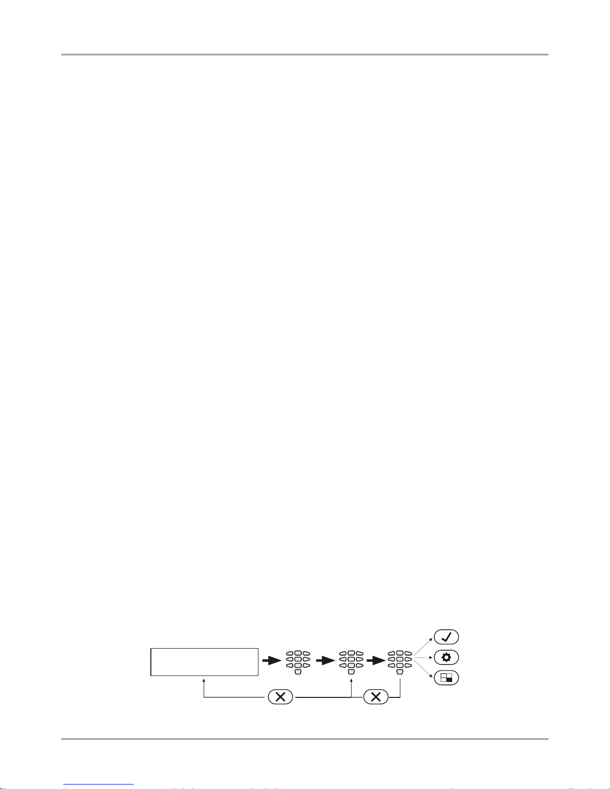
3-digit operations. The programming of the system parameters is organized with 3-digit operation codes. The
menus have the following structure:
o 0хх – General Settings Menu.
o 1xx – General User Menu; 1uu - Options for Users, as “uu” is an option number; after the option
number is necessary to enter a user number from 01 to 64.
o 2xx – General Zone Menu; 2zz – Zone options settings, as “zz” is an option number; after the option
number is necessary to enter a zone number from 01 to 32.
o 3xx – General Setting for PGM 4; 3pp – PGM options settings, as “pp” is an option number; after the
option number is necessary to enter a PGM number from 01 to 32.
o 4xx – General Areas Menu; 4aa – Area options settings, as “aa” is an option number; after the option
number is necessary to enter an Area number from 01 to 08.
o 5tt – Timeslot Menu, as “tt” in an option number; after the option number is necessary to enter an
Timeslot number from 01 to 08. In addition, at addresses 541 to 544 are set holidays and nonworking
days – and the number of the month from 01 to 12.
o 6хх – General Settings for the digital communicator; 6nn – Phones options settings; after the option
number is necessary to enter a phone number from 01 to 04.
o 67x – General settings for the voice dialer, where „х“ is number of an option from 0 to 3.
o 680 – Entering of telephone numbers for the voice dialer.
o 69х – General settings for UDL remote programming.
o 810 + dd – Device Menu, as “dd” is a device number from 01 to 31.
Note: The Device 01 is always the main PCB of the control panel.
<< LCD32 >>
10:05 06/08
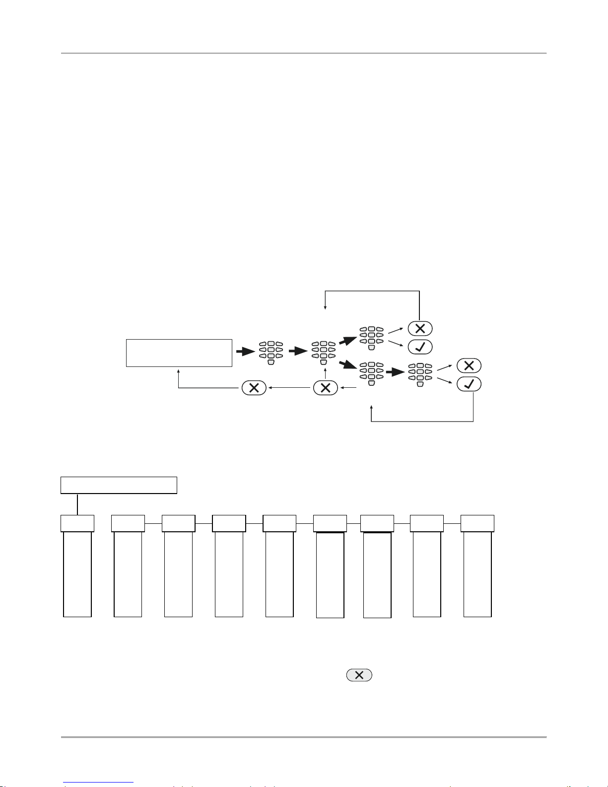
Text menus (tree-structure). The system parameters are organized in text menus with tree-structure:
To enter in a text menu select it with the arrow buttons and confirm with ENTER. The programming of the parameters
in the menus may differ according to their usage. Use the arrow buttons to scroll of the available menus or submenus.
You can also directly enter in a menu with pressing its number – see the structure above.
The exit to the upper menu or submenu is with pressing the CANCEL button.
Engineer
Code
3-digit
operation
Parameter
Settings
Cancel the entered settings
and return to the main menu
or
2-digit
menu
Parameter
Settings
Engineer Code (7777)
1
MAINTENANCE
2
SETTINGS
3
CODES
4
INPUTS
5
OUTPUTS
6
PARTITIONS
8
COMMUNICATION
9
DEVICES
► ◄ ► ◄ ► ◄ ► ◄ ►
◄
► ◄ ►
◄
7
SCHEDULES
►
◄
Page 6
Eclipse 8/ 16/ 32 Series - Engineer Programming Manual
6
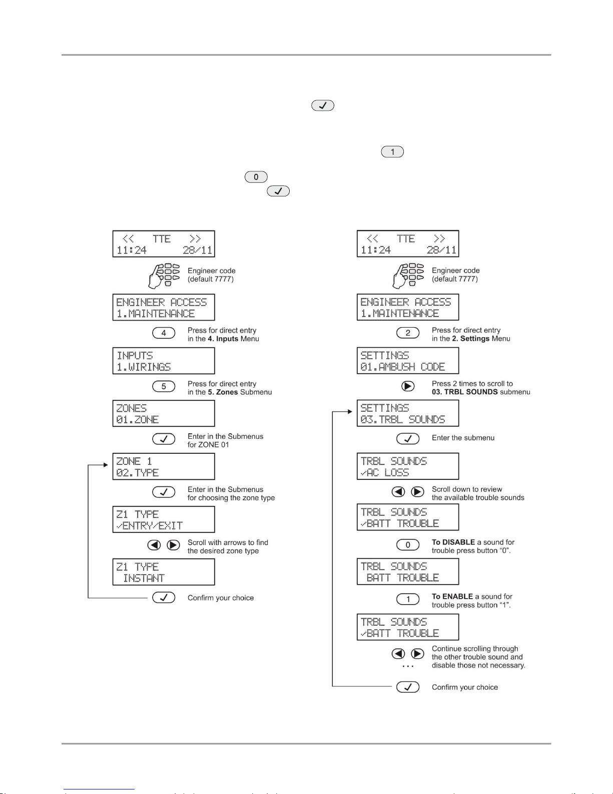
There are several ways for setting parameters – that depends on the menu:
- When the submenu allows choosing only one option or attribute, or parameter from a list, the installer
scrolls down to the desired one and confirms his choice with button. The set option is displayed with a “check”
mark in front of it. The exit of the submenu is automatic. See Example 1 below.
- When the submenu allows choosing of several options or attributes, or parameters at the same time then
the installer has to scroll down to each one and to enable it with pressing the button. The set option is displayed
with a “check” mark in front of it. The installer has to move to the next option using the arrow buttons and so on. To
disable an option scroll down to it and press button – the “check” mark will be deleted. When all the desired
options are selected, the choice is confirmed with button. See Example 2 below.
Example 1 (ECLIPSE 8)
Example 2 (ECLIPSE 8)
Page 7
Eclipse 8/ 16/ 32 Series - Engineer Programming Manual
7
2. SUPPORTED KEYBOARDS FOR PROGRAMMING AND OPERATION
Eclipse 8/16/32 alarm control panel supports operation with the full range of Eclipse Series keyboards.
ATTENTION: The operation with text menus is set by default for control panels ECLIPSE 8/16/32.
The text menus are accessible for operation with LCD keyboards.
In case of using a LED keyboard for programming and settings the 4-digits address menus are used
by default.
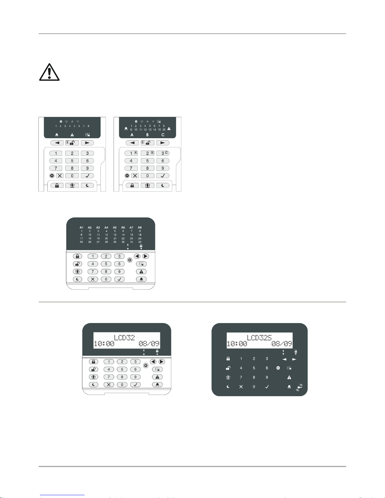
2.1. LED/LCD Keyboards
LED8
LED16A
LED8 / LED16А (open protective cover)
Supported programming style types:
4-digit address menus – by default
3-digit operation menus
The keyboard provides specialized LED indication about the
programming style and visualization of the selected
parameter, option or attribute with the digit buttons.
The installer can review the number of the entered address
or operation code using a special information button.
The general operation with LED8/ 16А keyboard is
described in item 2.5.
LED32 (open protective cover)
LED32 (open protective cover)
Supported programming style types:
4-digit address menus – by default
3-digit operation menus
The general operation with the keyboard is described in item
2.6.
LCD32 (open protective cover)
Supported programming style types:
4-digit address menus
3-digit operation menus
Text menus (tree-structure) – by default
LCD32 Sensitive
Supported programming style types:
4-digit address menus
3-digit operation menus
Text menus (tree-structure) – by default
The general operation with the keyboards is described in item 2.7.
Page 8

Eclipse 8/ 16/ 32 Series - Engineer Programming Manual
8
Summary for ECLIPSE Series Keyboards:
Keyboard
Display
Areas
Zones
Proxi
Address
Operation
Text menu
AUX PGM
LED 8
LED 1 8
LED 16
LED 2 16
LED 16A
LED 3 16
LED 32
LED 8 32
(option)
LCD 32
LCD
8
32
(option)
LCD 32S
LCD
8
32
2.2 Sound Signalization from the Keyboards
All Eclipse Series Keyboards have sound signalization for occurring of different system events. The sound signalization
has 4 volume levels adjustable at address 90 from the Manager programming menus.
Sound Signal
Description
Button
Single short beep indicating the pressing of a key.
Confirmation
Two long sound signals, indicating the system confirmation to executed operation.
Cancel
operation
A single long beep, indicating system incorrectly executed operation.
Entry time
Continuous beep, indicating intrusion into an entrance zone.
Exit time
Short beeps, indicating the system is armed and the user is required to leave the entrance zone.
Ten seconds before the exit time is over beep frequency increases.
Technical
problem
Two short beeps at every 20 sec, indicating a technical trouble. To stop the signalization - press the
TROUBLE button.
Chime
Short beeps with subsequently increasing period, indicating intrusion into a zone with an activated
chime option.
Fire alarm
Three sound signals in sequence repeated every 5 seconds. That kind of signalization shows
activated fire detector in the premises.
2.3. Supported Trouble Events in ECLIPSE Series
The possible system troubles are listed in the table below, together with the respective indication for LED and LCD
keyboards. The sound signalization for a system trouble can be disabled in menu 2. SETTINGS – 03. TRBL SOUNDS
(ADDRESS 0013 or OPERATION 013. By default, the sound signalization for all system troubles is enabled.
Note: The system troubles 7 and 8 are not supported for Eclipse 8/ 16 control panel.
LED
LCD
Description
1. AC Loss
The mains power supply is lost.
2. Battery Trouble
The accumulator battery is discharged or missing.
3. Blown fuse
Blown out fuse.
4. Tel. line TRBL/
Comm. Fail
Telephone line of the digital communicator is lost & communication with central Monitoring
station fails.
5. Tamper
Open tamper in system.
6. Sysbus err
System bus error. It could be short circuit in the line or lost device.
7. Fire line Error
Fire Detector Loss or the fire line is broken.
8. Siren Fault
Problem with connected siren; no siren connected to PGM5.
Page 9
Eclipse 8/ 16/ 32 Series - Engineer Programming Manual
9
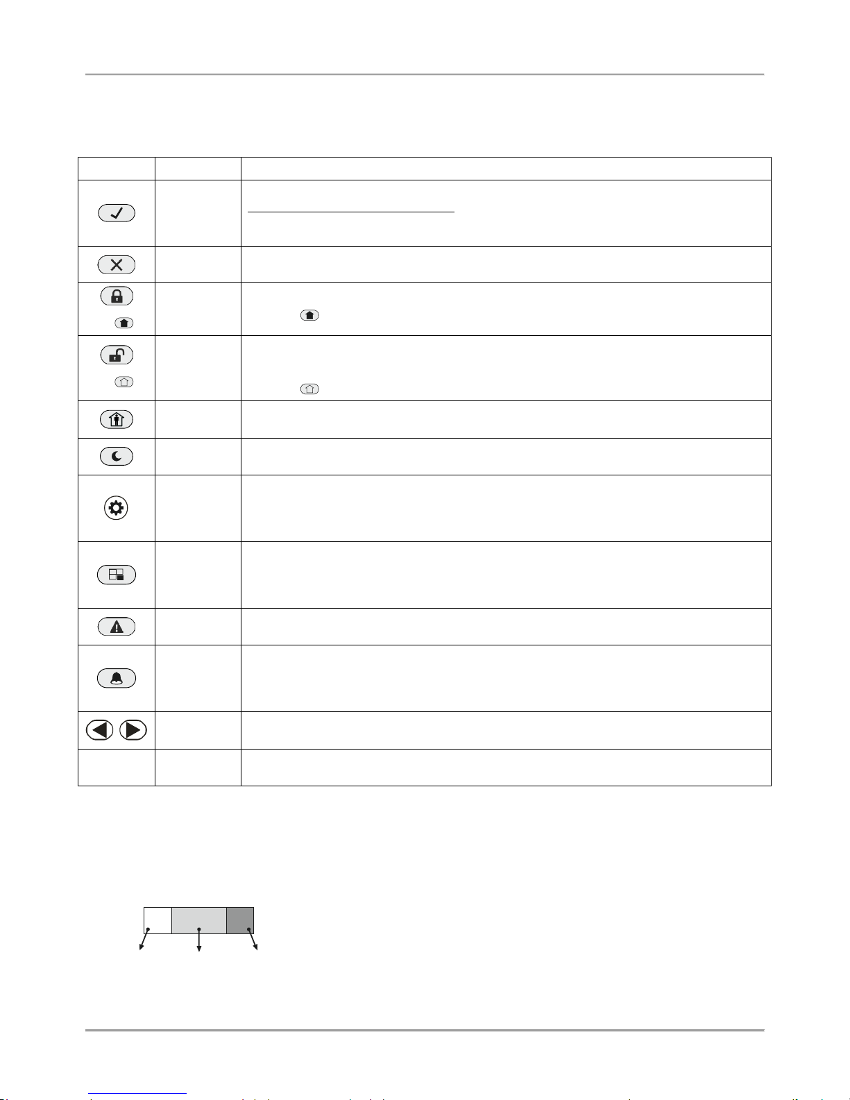
2.4. Buttons Functions
Note: The functionality of BYPASS, TROUBLE and MEMORY buttons for LED8 and LED16 (A) keyboards is
accessible through the manager and user menus only with the respective LED indication on the display.
The specialized LED indication of the LED8/ 16A keyboard is described in details in item 2.5.
Button
Function
Description
ENTER
Confirmation of the entered data; step ahead in the engineer programming menus*.
For LED8 and LED16 (A) keyboards: Use the button to review the memory log file, the
system troubles and the bypassed zones – the respective system LED is blinking during
the review.
CANCEL
Canceling the entered parameters; exit from a programming mode.
(or )
FULL ARM
Quick button for Full Arming Mode.
The button is used in the previous design of the keyboard and has the same functionality.
(or )
DISARM
Disarming the system. The button has a special function in text entering mode – deletes
the current symbol and moves the cursor on one position to the left (like Backspace button
on a standard PC keyboard).
The button is used in the previous design of the keyboard and has the same functionality.
STAY ARM
Quick button for Stay Arming Mode. The button has a special function in text entering
mode – shifting between small and capital letters.
SLEEP
ARM
Quick button for Sleep Arming Mode.
PRG
Entry in Manager and User programming modes. The button has a special function in
engineer programming mode – saving the entered settings and moves forward as the
current index number is increased with +1*.
Entry in Service Keyboard Mode.
BYPASS
Bypassing zones. The button lights on permanently if there are bypassed zones in the
system. The button is blinking during the bypassed zones review.
The button has a special function in engineer programming – canceling the entered
settings and moves forward as the current index number is increased with +1*, option 0.
TROUBLE
Reviewing the system troubles. The button lights on permanently if there are system
problems. The button is blinking during the system troubles review.
MEMORY
Reviewing the memory events log file. The button lights on permanently if there are
memory events. The button is blinking during the memory events review. The button has a
special function in text entering mode – entering of special symbols (see the item 2.8
Entering text for LCD Keyboard).
Scroll
arrows
Arrows for moving the cursor on the left and on the right in programming mode.
0 - 9
Digit
Buttons
Digital buttons for entering parameters, codes, etc.
* The functionality is available in 4-digit address programming style.
The structure of the addresses is as follows:
X Y Y Z
Menu
number
Option
Index
number
Example for ECLIPSE 32:
When pressing PRG button, the next viewed address is formed as the current
index number is increased +1 and option number is the same. Example, from
ADDRESS 2021 after pressing PRG the menu moves to ADDRESS 2031.
When pressing BYPASS button, the next viewed address is formed as the
current index number is increased +1 and option is first possible. Example,
from ADDRESS 2024 after pressing BYPASS the menu moves to ADDRESS
2030.
Page 10
Eclipse 8/ 16/ 32 Series - Engineer Programming Manual
10
2.5. General Information for Operation with LED8/ 16A
LED8/ 16A are a compact size keyboards with LED display, suitable for management and programming of ECLIPSE
Series control panels. The keyboards have indication for 8/ 16 zones and can control one 1/ 3 area.
LED8/ 16A are equipped with specialized LED indication for informing the installer of the set programming style menu
and specific visualization of the programming values and parameters.
The entering of codes, 3- and 4-digit addresses and values is with the digit buttons. For arming the system are used
the quick buttons for the respective arming mode.
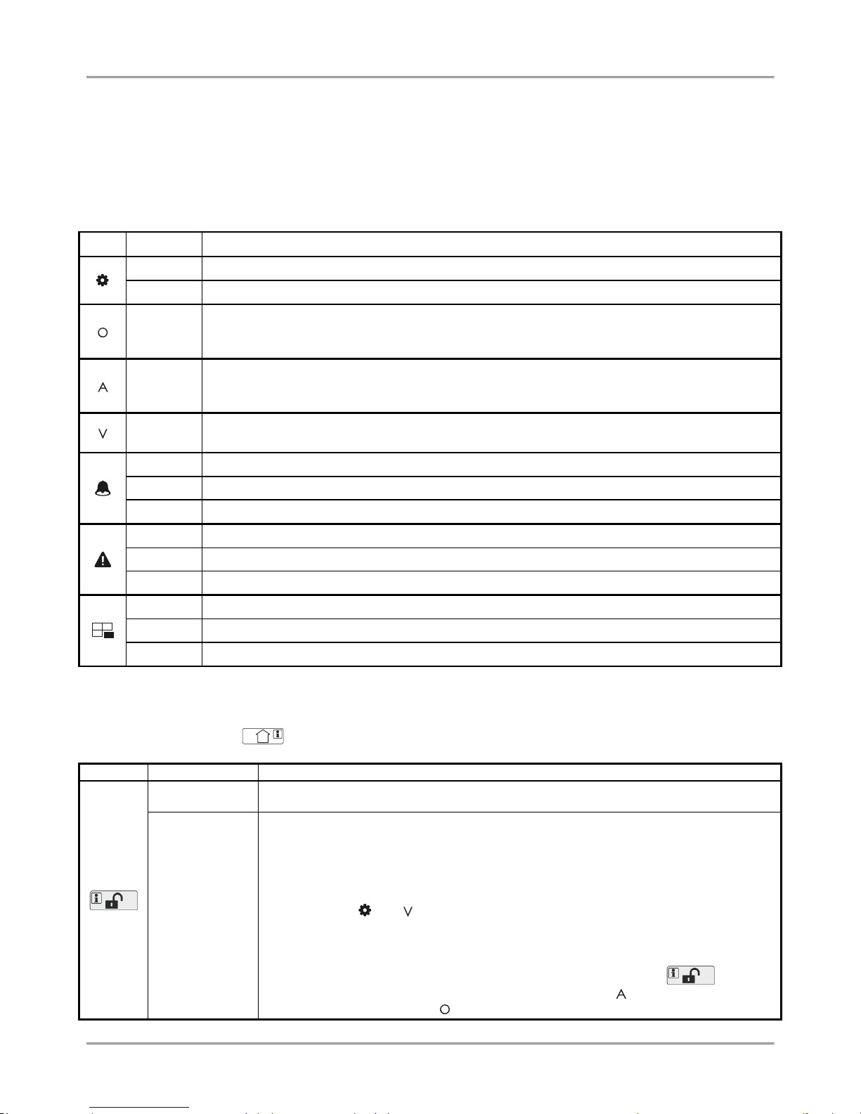
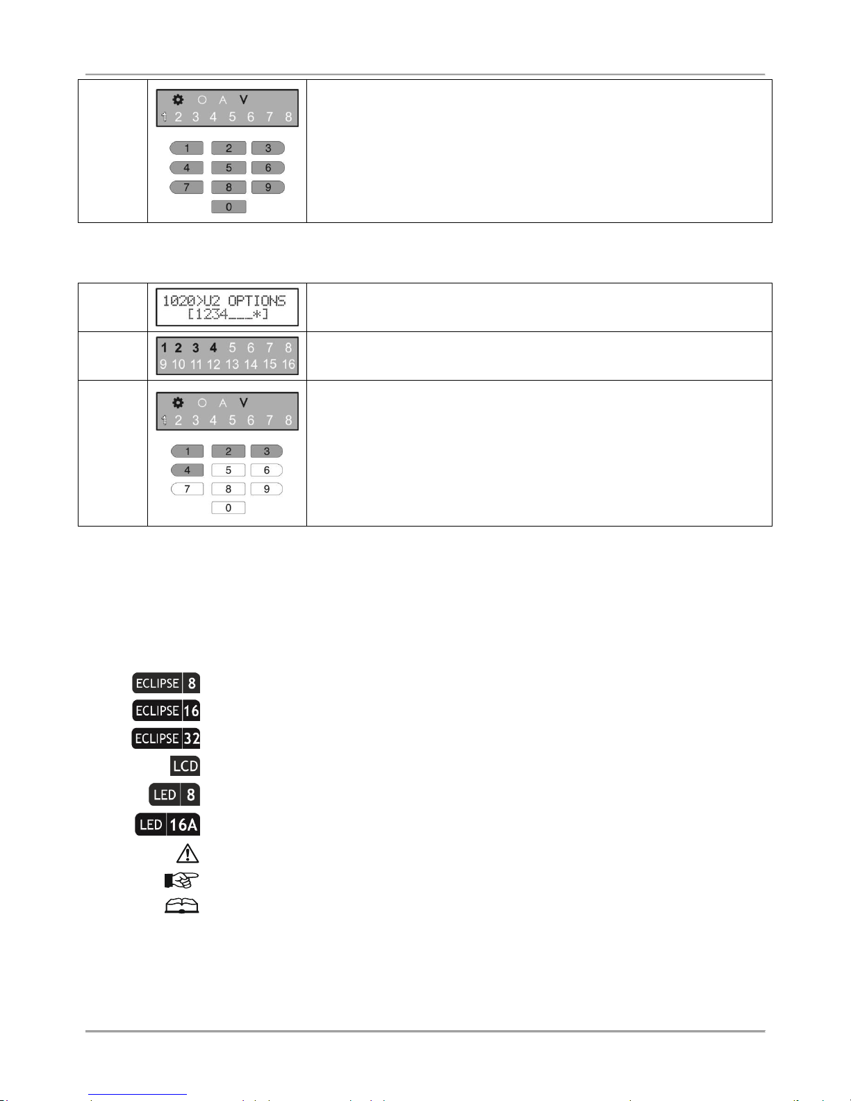
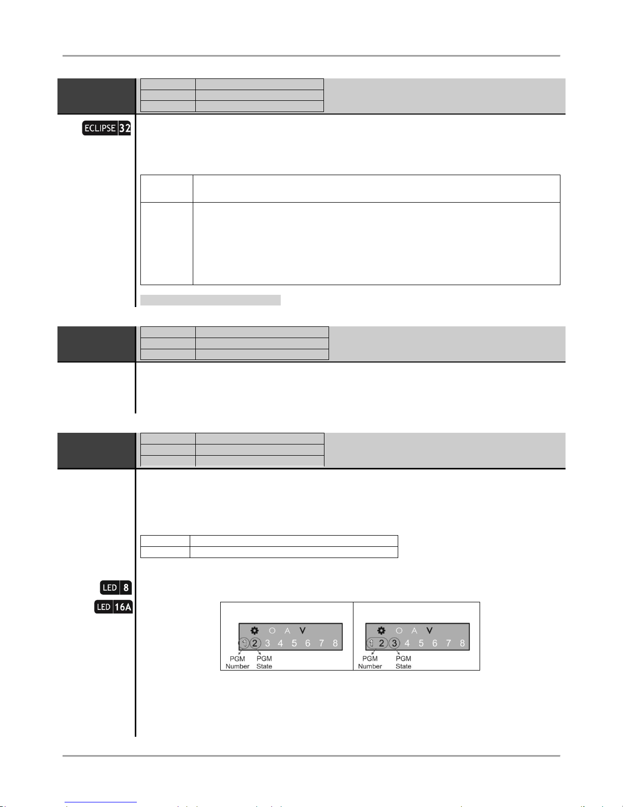
Specialized LED indication for LED8/ 16A keyboard:
LED
Indication
Description
Lights on
The system is in engineer or manager programming mode.
Blinking
Shows a selected device in an engineer programming mode.
Lights on
The 3-digit programming style type is selected.
View mode (of OPERATION number) after pressing the DISARM button.
[O] is short from OPERATION.
Lights on
The 4-digit programming style type is selected.
View mode (of ADDRESS number) after pressing the DISARM button.
[A] is short from ADDRESS.
Lights on
The system waits for entering of setting of a parameter, or option.
[V] is short from VALUE.
Lights off
No active alarms in the system.
Lights on
Alarm in the system. The active alarms are reviewed by pressing the ENTER button.
Blinking
View mode for active alarms.
Lights off
No system troubles in the system.
Lights on
System trouble. The active troubles are reviewed by pressing the ENTER button.
Blinking
View mode for system troubles.
Lights off
No bypassed zones in the system.
Lights on
Bypassed zones in the system. The zone numbers are reviewed by pressing the ENTER button.
Blinking
View mode – The numbers of bypassed zones are lighting on.
In normal operation mode the DISARM button (LED8) or Area Letters (LED 16A) light on in green. The DISARM button
has a specific functionality in engineer programming menus.
Note: The button DISARM used in the previous design of the keyboard and has the same functionality!
Button
Functionality
Description
DISARM
System disarming.
INFORMATION
Information about the ADDRESS number in engineer programming mode. The
functionality is useful when the installer is confused during the engineer programming
and wants to check up the current ADDRESS number before continue with the
respective parameter or option settings.
The button is used in the following way:
1. The symbols and are lighting on permanently together with a number of
zone(s), according the type of the programmed parameter. A blinking digit shows that
parameter which is in setting mode, and lighting on digit button shows the current set
value for this parameter.
2. To find out what is the number of the current ADDRESS, press the button. If
the set programming style is with 4-digit ADDRESSES – the symbol lights on, and if it
is with 3-digit operations - the symbol lights on. The zone numbers from 1 to 4 or
Page 11
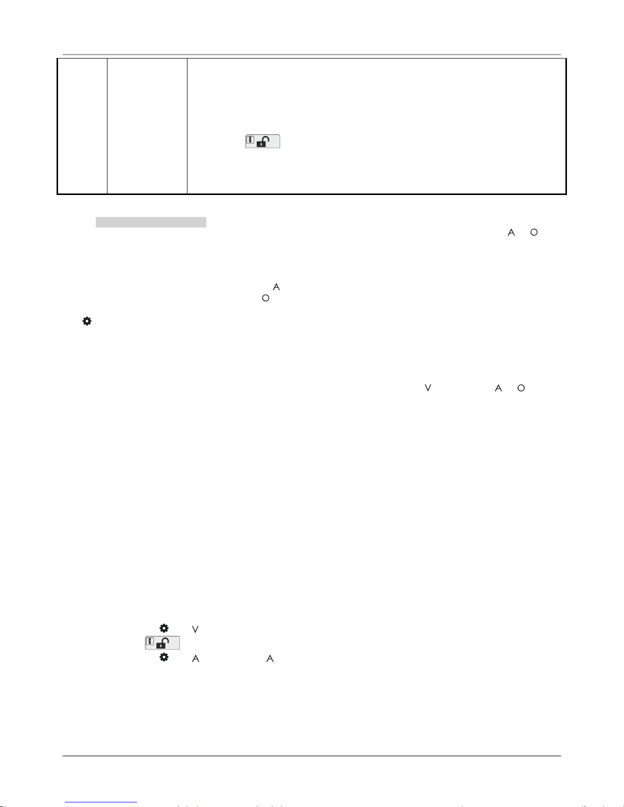
Eclipse 8/ 16/ 32 Series - Engineer Programming Manual
11
from 1 to 3 are lighting on, the zone 1 is blinking, and lighting on button shows the first
digit of the address (operation) number.
3. Press the right arrow button. The cursor will move one position on the right, zone 2
starts blinking and lighting on digit number shows the next number of the address (or
operation).
4. Proceed in an analogical way reviewing the address number up to the last digit.
5. Press the button again to step back in parameter setting mode.
Note: You can also leave the view mode and with single pressing the CANCEL button.
Recommendation: If you are not familiar in details with the engineer programming
menus (address and operation numbers) write down in sequence the digits (of lighting
buttons) corresponding to the respective address positions (zone numbers).
- Engineer Programming
The engineer programming menus are accessible only when the system is disarmed. Lighting on symbols or
indicate the currently set programming style type.
To access the engineer programming menus enter valid engineer code (7777 by default). A confirmation sound signal
is heard and the system starts waiting for the installer to enter ADDRESS or OPERATION number for programming.
According the set programming style, the LED displays:
- The zone numbers 1, 2, 3 and 4, and lighting on - 4-digit ADDRESS programming style
- The zone numbers 1, 2 and 3, and lighting on - 3-digit OPERATION programming style
The symbol lights on permanently together with the letter for the set programming style – 4-digit ADDRESS
programming style is set by default.
To proceed with programming, enter ADDRESS number and according the descriptions provided in item 7, set
parameters, attributes and options for the system configuration. Use the digit buttons to enter the address number.
Every pressing of a button turns one zone number off, and the pressed button lights on. After pressing the last digit of
the address number, the system enters automatically in mode for setting parameters - lights on, and or light
off.
Several zone numbers will light on as their number depends on the current parameters for programming. Zone 1 is
blinking to show that the first digit of the value is currently set. A permanently lit digit button shows the current set
value. To change it, press other digit button according the parameter. If there are several values (when setting the date
for example), you can review them using the arrow buttons. Note: In case of setting options from ENABLE/ DISABLE
type keep in mind that the opting is disabled when all digit buttons are off, and the option is enabled when all digit
button are lighting on. You can change the setting of the option with pressing random digit button or arrows buttons.
To confirm the entered settings press the ENTER button – the system automatically moves to the next address
number. To cancel the entered parameters press the CANCEL button – the system will move back to the main screen
for ADDRESS entry. To exit to main screen press CANCEL button a couple of times. In normal operation mode only
the DISARM button lights on in green.
According the entered ADDRESS number the LED indication will differ. Use the detailed descriptions in item 7 to
become familiar with the system settings.
Attention: The exit from the engineer programming menus is not automatic! Press CANCEL button several times to
exit to the main display and normal operation mode – only the DISARM button lights on in green.
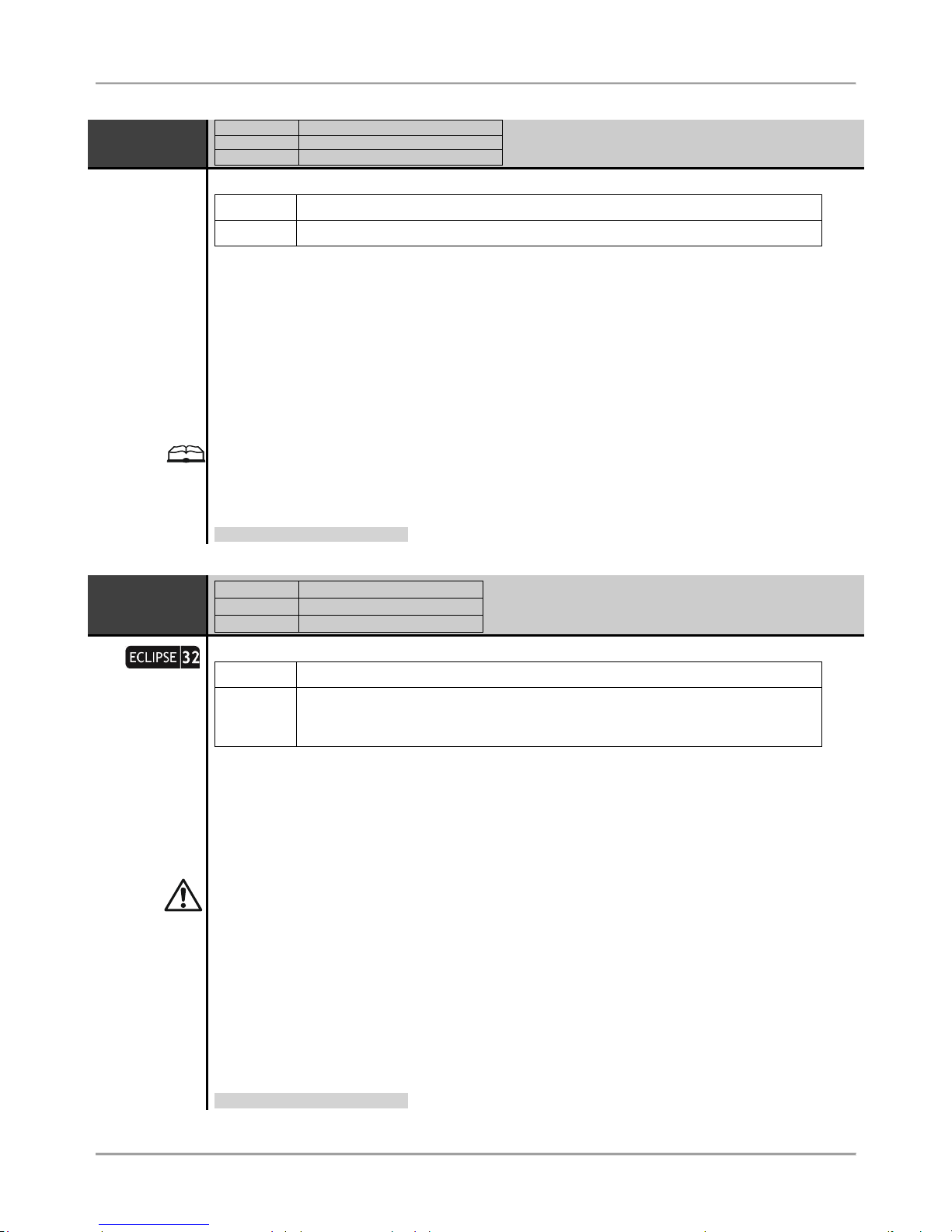
Example for reviewing of ADDRESS number in engineer menu with LED8/ 16A keyboard:
- The symbols and are lighting on. Zone 1 is blinking and Button 1 lights on.
- Press the button. It starts blinking showing that the system is in mode for address reviewing.
- The symbols and light up. Letter means that the set programming style is with 4-digit ADDRESSES.
- Zone 1 is blinking. Button 0 is lighting on – this is the first digit of the ADDRESS number.
- Press the right arrow button.
- Zone 2 is blinking. Button 0 is lighting on – this is the second digit of the ADDRESS number.
- Press the right arrow button again.
- Zone 3 is blinking. Button 9 is lighting on – this is the third digit of the ADDRESS number.
- Press the right arrow button for the last time.
- Zone 4 is blinking. Button 7 is lighting on – this is the last digit of the ADDRESS number.
Page 12

Eclipse 8/ 16/ 32 Series - Engineer Programming Manual
12
- The reviewed ADDRESS number is 0097 – Changing the programming style type.
- To go back to the parameter settings mode press the button again.
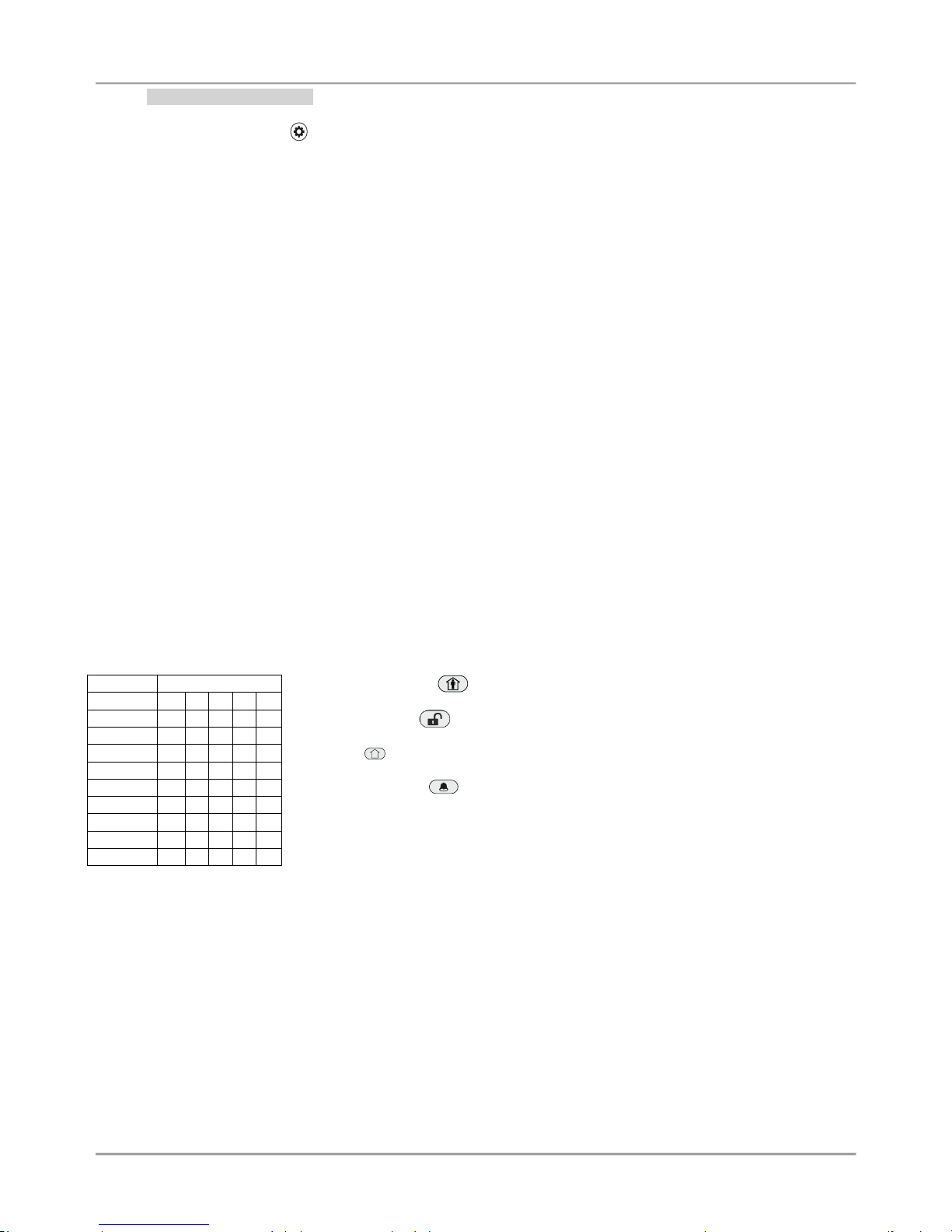
- Manager Programming
To access the manager programming menus enter valid manager code (0000 by default). A confirmation sound signal
will be heard. Press the PRG ( ) button to enter in manager programming menus. Zone numbers 1 and 2, and LEDs
and are lighting on. The manager programming menus are 2-digit and are described in details in ECLIPSE
Series Operation Manual – Manager and User Programming. If 30 sec after entering the manager programming there
is no activity (pressed button), the system will exit in normal operation mode. It is possible to enter in manager
programming menus from several keyboards at a time using the same manager access code.
Example for date setting in Manager programming menus using LED8/ 16A keyboard:
- Enter valid Manager code (0000 by default) and press button.
- LEDs and are lighting on. Zone number 1 is blinking, and 2 is lighting on – the system waits for entering
of 2-digit ADDRESS number.
- Enter 15 – ADDRESS for date setting.
- LEDs and are lighting on. Zone number 1 is blinking, zones from 2 to 6 are lighting on. The “0” digit
button is lighting on (the set date by default is 01/01/12).
- Enter the new date using the format DDMMYY. You can use the buttons with arrows to review the entered
new date before saving it – the lighting on digit button shows the set value for every currently blinking zone number on
the display.
- Confirm the new set date with ENTER.
2.6. General Information for Operation with LED16 and LED32
LED 16 and LED 32 are keyboards with LED display, suitable for management and programming of ECLIPSE Series
control panels. LED 16 has indication for 16 zones and can control 2/3 independent areas. LED 32 has indication for
32 zones and can control 8 independent areas.
The keyboards LED 16(A) and LED 32 operate with limited functionality when connected to ECLIPSE 8 control panel –
operation with one area (A in LED16) and 8 zones. LED 32 operate with limited functionality when connected to
ECLIPSE 16 control panel – operation with three areas (A, B and C) and 16 zones.
- Engineer Programming
The engineer programming menus are accessible only when the system is disarmed.
According to the set programming style after entering an engineer code (7777 by default) the LED displays:
- The zone numbers 13, 14, 15 and 16 lighting on - 4-digit ADDRESS programming style
- The zone numbers 14, 15 and 16 lighting on -3-digit OPERATION programming style операции
The both LEDs „lightning” (white) and „padlock” (red) are blinking together showing that the system is in engineer
programming mode. Now, the system waits for entering of ADDRESS or OPERATION for programming – by default
the 4-digit ADDRESS programming style is set.
Use the digit buttons to enter an ADDRESS number – the detailed description of the ADDRESSES and their
functionality is provided in item 7. Every pressing of a button enters one digit and the lighting on zone numbers are
reduced with one, the number of the pressed digit button lights up (for 0 lights on digit 10). According the entered
address number the indication for the parameters is different. Use the address descriptions provided in item 7 to
orientate for the required settings. To confirm the entered settings press the ENTER button, to reject them – the
CANCEL button. To return to the display for address entering press single the CANCEL button. To exit the engineer
programming menu press the CANCEL button once again. The keyboard is in normal operation mode when LEDs
“Lightning” (white) and “padlock” (green) are lighting on together with the numbers of the used areas.
Attention: The exit of engineer programming menu is not automatic! To exit the engineer menu press CANCEL button
several times until return to the normal operation mode.
Page 13
Eclipse 8/ 16/ 32 Series - Engineer Programming Manual
13
- Manager Programming
To access the manager programming menus enter valid manager code (0000 by default). A confirmation sound signal
will be heard. Press the PRG ( ) button to enter in manager programming menus. Zone numbers 15 and 16 are
lighting on, and both LEDs “Lightning” and “padlock” are blinking only on the keyboard for programming. The manager
programming menus are 2-digit and are described in details in ECLIPSE Series Operation Manual – Manager and User
Programming. If 30 sec after entering the manager programming there is no activity (pressed button), the system will
exit in normal operation mode. It is possible to enter in manager programming menus from several keyboards at a time
using the same manager access code.
2.7. General Information for Operation with LCD Keyboard
The LCD32 and LCD32 Sensitive are keyboards for management and control with text LCD displays.
The keyboards LCD32 and LCD32 Sensitive operate with limited functionality when connected to ECLIPSE 8/ 16
control panel – operation with one area and 8 zones.
To enter codes, addresses and parameters use the digit buttons. For arming the system can be used neither the quick
buttons with the respective pictograms, or to choose the arming type from the screen scrolling with the arrows and
confirmation with ENTER button. Use the provided in item 7 detailed descriptions of the all addresses in the system. To
exit the engineer or manager programming menu press CANCEL button several times until return to main screen in
normal operation mode.
2.8. Entering text for LCD Keyboard
The keyboard models LCD32 and LCD32 Sensitive support text entering including small and capital letters (Cyrillic and
Latin), digits, punctuation marks and other specific symbols
The regular letters and digits can be entered directly by the buttons or as a code combination after pressing the
MEMORY button – look at the tables below.
It is possible to enter text up to 16 symbols including space.
Table for correspondence of the buttons:
Button
Letters, digits
0
_ 0 1 1 2 a b c 2 3 d e f 3 4 g h i 4
5
j k l 5 6 m n o 6 7 p q r s 7 8 t u v 8 9 w x y z 9
Use the STAY ARM button to enter capital letters.
Use the DISARM button to delete a symbol – the cursor moves with one step to
the left.
The button is used in the previous design of the keyboard and has the same functionality!
Use the MEMORY button to enter some special symbols and Cyrillic letters.
To enter a specialized symbol, move the cursor to the desired position, press the
MEMORY button (a solid cursor appears) and then using the digit buttons enter the
respective code for the symbol or letter as check in the table below.
Page 14
Eclipse 8/ 16/ 32 Series - Engineer Programming Manual
14
Table of the symbols and codes correspondence:
064 080 096 112
065 081 097 113
066 082 098 114
067 083 099 115
068 084 100 116
069 085 101 117
071 087 103 119
070 086 102 118
073
075
077
072
074
076
078
079
089
091
093
088
090
092
094
095
105
107
109
104
106
108
110
111
121
123
125
120
122
124
126
127
160
161
162
163
164
165
167
166
169
171
173
168
170
172
174
175
176
177
178
179
180
181
183
182
185
187
189
184
186
188
190
191
192
193
194
195
196
197
199
198
201
203
205
200
202
204
206
207
208
209
210
211
212
213
215
214
217
219
221
216
218
220
222
223
224
225
226
227
228
229
231
230
233
235
237
232
234
236
238
239
240
241
242
243
244
245
247
246
249
251
253
248
250
252
254
255
048
049
050
051
052
053
055
054
032
033
034
035
036
037
039
038
041
043
045
040
042
044
046
047
057
059
061
056
058
060
062
063
Example: To enter the „asterisk” symbol, first press the MEMORY button (a solid cursor appears on the place)
and after that enter code 042. The asterisk symbol will appear and the cursor will move one position to the
right.
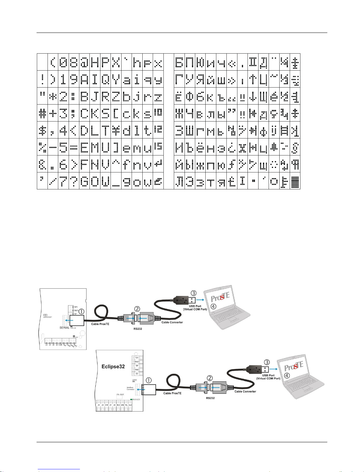
3. PROGRAMMING WITH SPECIALIZED ProsTE SOFTWARE
ProsTE is specialized software for direct programming of burglary and fire alarm panels manufactured by Teletek
Electronics JSC.
The programming of ECLIPSE Series control panels is via serial connection using specialized “cable ProsTE”. It is
strongly recommended as a first step to read the set to control panel parameters, as second – changing parameters
and at the end – writing the new settings to the control panel.
A detailed description for the operation with ProsTE software is provided in the built-in help files.
Serial connection between the ECLIPSE 8 / 16/ 32 and PC with ProsTE software
Eclipse 8/ 16
Page 15

Eclipse 8/ 16/ 32 Series - Engineer Programming Manual
15
4. OPERATION WITH A SERVICE KEYBOARD
The service keyboard is a device, which is not a part of the system configuration, but can provide full access to all
engineer programming menus. Every keyboard of Eclipse Series can be used as service, when it is not enrolled at
address in the system configuration.
The service keyboard is not enrolled at a certain address and that is why its removing will not cause a system trouble
for a lost device.
To enter the “Service keyboard” mode press the PRG ( ) button after powering up the keyboard.
You can connect only one service keyboards to the system configuration at the same time.
The “Service keyboard” mode allows access only to the engineer programming menus and the Manager and User
programming menus are not available. The system arming and disarming is also unavailable.
Every Eclipse Series keyboard can be service keyboard if it is not currently connected and enrolled to the system
configuration.
To enter the “Service keyboard” mode with a new keyboard:
- Connect the keyboard to the system bus and wait the initial initialization to complete.
- Single press the PRG button ( ).
- A confirmation sound signal is heard indicating that the keyboard is ready for operation.
- When you finish with the engineer programming, exit to the main screen.
- Power off the keyboard and disconnect it from the system.
To enter the “Service keyboard” mode with a present keyboard in the system configuration:
- Use one of the other keyboards in the system configuration to delete the unique ID number of the one
selected for service keyboard – enter the keyboard ID address 8xx0, where “xx” is the device number from
02 to 32 (01 is always the PCB of the control panel), and delete the ID number with pressing the “0” button
for 2-3 seconds. It is not necessary to confirm with ENTER.
- Power off the keyboard for a moment – disconnect it from the system bus for 5-6 seconds.
- Connect the keyboard to the system bus again and wait the initialization to complete.
- Press the PRG ( ) button.
- A confirmation sound signal is heard indicating that the keyboard is ready for operation.
- When you finish with the engineer programming, exit to the main screen.
- Power off the keyboard and disconnect it from the system bus.
ATTENTION: If the engineer access is disabled from the manager programming menu the access will be
denied and for the service keyboard!
5. ENROLLING / DELETING OF DEVICES
5.1. Enrolling Devices during the Initial Start-up of the Control Panel
1. With set RESET jumper on the main PCB power up the Eclipse control panel.
2. Wait the initial initialization of the connected to the system bus keyboards. At the end of the procedure, the
bus LED of all devices including the main PCB is lighting permanently in red. A text message “SW revision XX;
Press ENTER” is displayed on LCD screen, and at LED keyboards is lighting on only the power LED. For LED
8/ 16A only buttons are lighting on.
3. Start to press the ENTER button or tamper-switch of the devices – the manufacturer recommends first to
enroll the keyboards in the system, then proxy readers, modules, etc. The system starts an automatic
enrollment procedure of the devices on consecutive addresses starting with address 8020. Remember that the
first enrolled device to the system bus is always the main PCB of the panel. It is strongly recommended the
next enrolled device to be a LCD keyboard for programming.
4. Remove the RESET jumper and wait the system bus LED to stop blinking in green. The system is ready for
further programming and parameter configuration.
IMPORTANT NOTE!
When enrolling devices to ECLIPSE 8 control panel, the first is automatically added to ZONE 7, and
the second to ZONE 8!
Page 16
Eclipse 8/ 16/ 32 Series - Engineer Programming Manual
16
5.2. Enrolling Devices to a working system configuration via LCD keyboard
1. Enter engineer code (7777 by default).
2. Press button “9” for direct access to menu “9. DEVICES”. Use the buttons with arrows to reach a free
address position for adding a new device. Choose in sequence:
ХХ. Device [Free] – ENTER – 1. ID – ENTER – [Free] [________]
3. Press the ENTER button (for a keyboard), the tamper-switch (for modules and standalone proxy reader) or
approach a proxy card (for a reader) of the device connected to the system bus and which you want to enroll to
the system configuration.
4. After successful enrollment to the control panel, the screen displays:
[Device type] [unique ADDRESS] for the respective device.
The following device types are supported from ECLIPSE Series:
Device
Description
ECLIPSE 8*
ECLIPSE 16**
ECLIPSE 32***
MAIN
The main PCB of the control panel
LED
Keyboard LED8/ 16/ 32
LCD
Keyboard LCD 32/ 32S
ZEXP
Zone expander
PEXP
PGM expander
WEXP
Wireless expander
PRX
Proximity card reader
* Eclipse 8: Up to 2 devices can be enrolled to the system bus: 2 keyboards, 2 proximity card readers or 1
keyboard and 1 proximity card reader.
** Eclipse 16: Up to 5 devices can be enrolled to the system bus irrespective of their type.
*** Eclipse 32: Up to 31 devices can be enrolled to the system bus irrespective of their type.
NOTE: It is not necessary to enroll the built-in proximity reader in keyboards LED 32, LCD 32 and LCD 32S.
5. Press ENTER button of the used for programming keyboard. The keyboard will confirm the end of the
successful enrollment procedure with sound signal.
6. The new enrolled device is in normal operation mode and ready for further programming and configuration.
* Note: Other way for enrolling of a new device is to enter its unique ID number directly at a free address as use the
digit buttons and some button combinations – see the table below. The unique ID number is provided from the
manufacturer with a sticker on the backside of the PCB of the device.
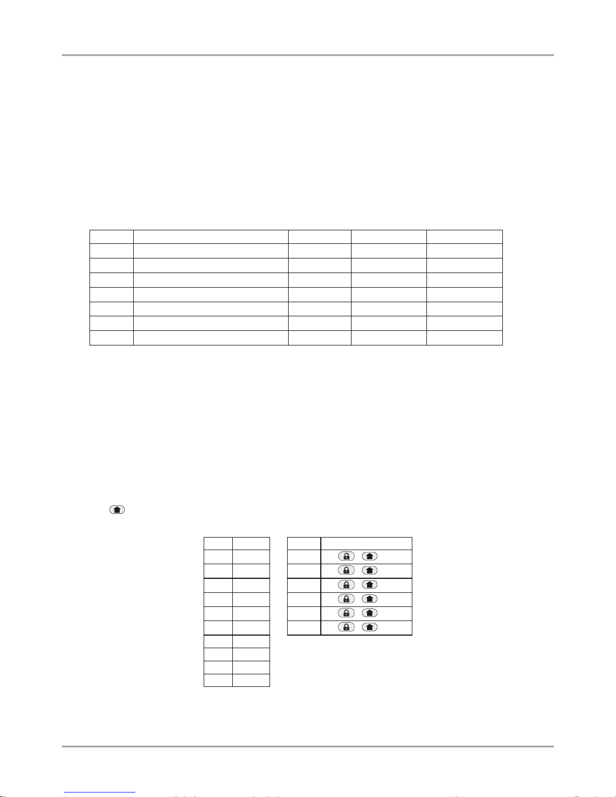
The button is used in the previous design of the keyboards and has the same functionality.
Digit
Button
Letter
Button Combination
0 0
A
/ + 0
1 1
B
/ + 1
2 2
C
/ + 2
3 3
D
/ + 3
4 4
E
/ + 4
5 5
F
/ + 5
6 6
7 7 8 8
9 9
Page 17
Eclipse 8/ 16/ 32 Series - Engineer Programming Manual
17
5.3. Enrolling Devices to a working system configuration via LED keyboard
1. Enter engineer code (7777 by default) – zone numbers 13, 14, 15 and 16 are lighting on. (For LED 8/ 16A –
1, 2, 3 and 4).
2. Enter ADDRESS 8020 and press BYPASS button several times until you reach a free address in the system
–zone numbers from 1 to 16 are lighting on. (For LED 8/ 16A – button “0” is lighting on).
3. Press the ENTER button (for a keyboard) or the tamper-switch (for module, proxy reader or other) of the
device you want to enroll to the system configuration.
4. After successful enrollment to the control panel, the screen displays a lighting on zone number according the
type of the enrolled device (for LED 8/ 16A a lighting button):
Number
Description
ECLIPSE 8*
ECLIPSE 16**
ECLIPSE 32***
1
The main PCB of the control panel
2
Keyboard LCD 32/ 32S
3
Keyboard LED8/ 16/ 32
4
Zone expander
5
PGM expander
6
Wireless expander
7
Proximity card reader
* Eclipse 8: Up to 2 devices can be enrolled to the system bus: 2 keyboards, 2 proximity card readers or 1
keyboard and 1 proximity card reader.
** Eclipse 16: Up to 5 devices can be enrolled to the system bus irrespective of their type.
*** Eclipse 32: Up to 31 devices can be enrolled to the system bus irrespective of their type.
NOTE: It is not necessary to enroll the built-in proximity reader in keyboards LED 32, LCD 32 and LCD 32S.
5. Press ENTER button of the used for programming keyboard. The keyboard will confirm the end of the
successful enrollment procedure with sound signal.
6. The new enrolled device is in normal operation mode and ready for further programming and configuration.
5.4 Deleting of a device from the system configuration
1. Enter engineer code (7777 by default)
2. Enter the address of the device you want to delete from the system configuration.
3. At the respective address press and hold the button “0” for 2-3 seconds – the LCD shows [Free] for the
address, LED 16/ 32 – LEDs from 1 to 16 are lighting on, LED 8/ 16A – button “0” lights on. A continuous
sound signal is heard. Attention: Deleting the unique ID number with button “0” is permanent and you
cannot reject the operation with CANCEL button! To enroll the device again follow the procedure
described at items 5.2 and 5.3.
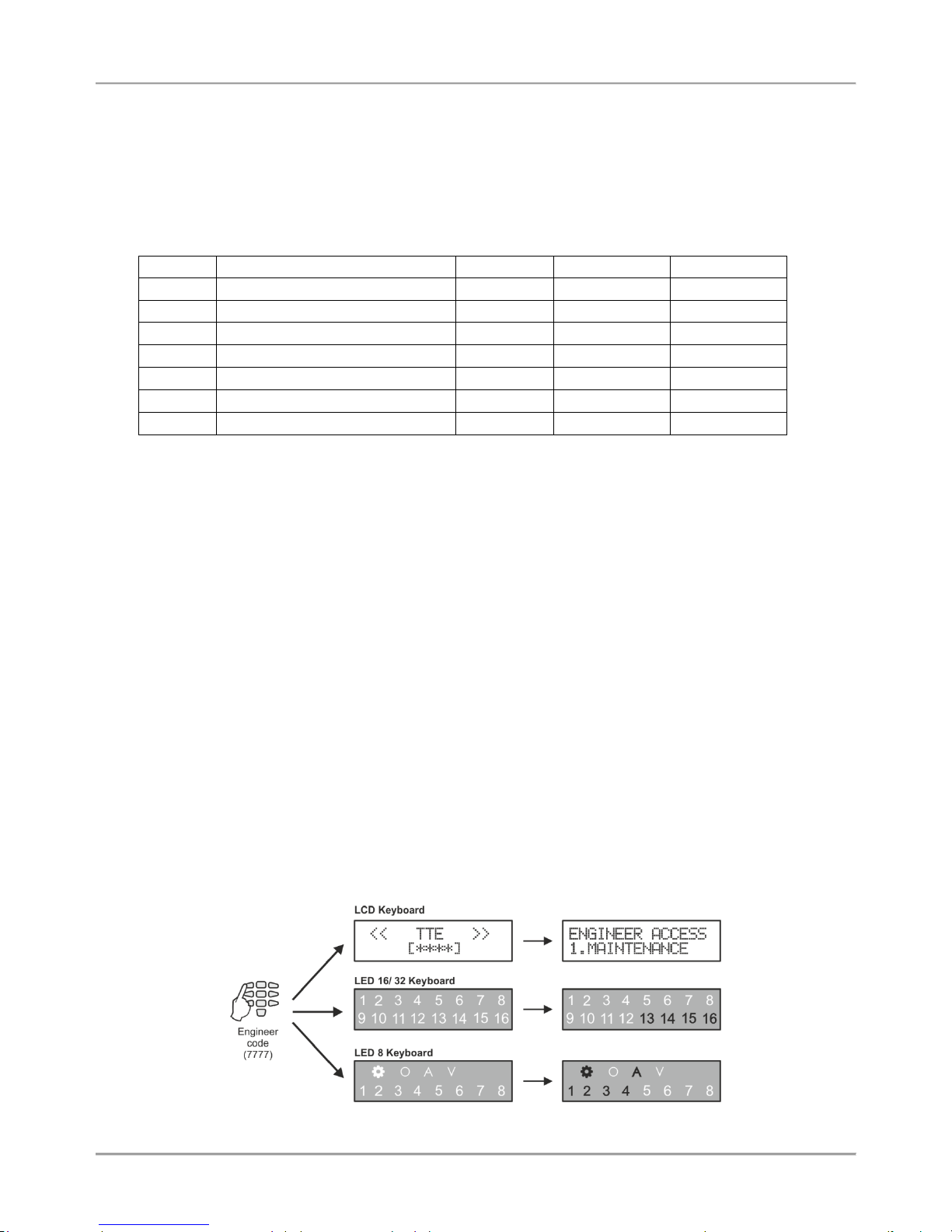
6. ENGINEER PROGRAMMING
The Engineer programming menus are available only when the system is fully disarmed. By default, the engineer
access code is 7777.
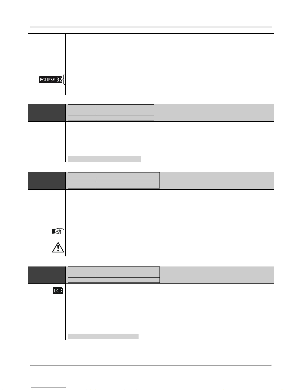
The display performance is different according to the used keyboard model for programming:
Page 18
Eclipse 8/ 16/ 32 Series - Engineer Programming Manual
18
The access to the Engineer programming menus is from one keyboard only while all other connected to the system
bus keyboards are temporally disabled for any operation. The LCD keyboards display a message „Engineer Mode!!!”
The default programming style is the one using text tree-structure for the engineer menus. To change the programming
style at the beginning you have to enter first the engineer menu with valid code (7777 by default) and choose in
sequence:
7777 – 2.SETTINGS – 14. MENU STYLE: TEXT, ADDRESS or OPERATION
Confirm your final choice with ENTER.
At every exit from the engineer programming menu the system updates all changes of parameters and settings. The
update will take some time depending on the system structure, volume and number of parameters’ changes.
Before starting the programming of any system parameter read carefully the provided detailed information for
each menu and make sure that you understand the descriptions.
6.1 Organization of the Engineer Programming Menus
For Installer’s convenience, every programming parameter description includes the access via all the programming
types:
ENG1 CODE
ADDRESS
0000
OPERATION
000
TEXT MENU
3. CODES – 2. ENGINEER – 1. ENG1 CODE
Important Notes!
6.2 Indication
The indication while programming different system parameter is performed in several common types according the
structure of the address or operation.
- Indication for introducing time values
LCD
Enter the new time using the digit buttons. The time interval varies according
the parameter. For values smaller than 10 enter “00” in front of it – for example
005.
LED 16/
LED 32
The zones 14, 15 and 16 show the number of the digits of the parameter. The
zones from 1 to 10 show the current set value for every digit, as 10 means 0.
The currently set digit is blinking. Use the arrows to review the values set to all
digits. For example, the zone 14 is blinking – the first digit of the parameter
and its value is 0 (10 lighting on). Move to the right to review the set value for
the second digit – zone 15 is blinking and 1 is lighting on. Enter the new time
using the digit buttons. Every pressing of a button sets new value and
automatically moves the cursor to the right.
LED 8/
LED 16A
The zones 1, 2 and 3 show the number of the digits of the parameter. LED
symbol “V” is lighting on to show that the system is in value programing mode.
Lighting on digit button shows the current set value for every digit.
- Indication for introducing parameter “ENABLE/ DISABLE” type
LCD
“DISABLE” or “ENABLE” is displayed on the screen. Press random digit button
or arrows to switch over.
LED 16/
LED 32
The “ENABLE” parameter is set when the zone numbers from 1 to 8 are
lighting on; The “DISABLE” parameter is set when all zone numbers are off.
Press random digit button or arrows to switch over.
Programming
Parameter
Menu type
Access
Page 19
Eclipse 8/ 16/ 32 Series - Engineer Programming Manual
19
LED 8/
LED 16A
The zone 1 is blinking and LED symbol “V” is lighting on to show that the
system is in value programing mode.
The “ENABLE” parameter is set when digit buttons from 0 to 9 are lighting on;
The “DISABLE” parameter is set when all digit buttons are off. Press random
digit button or arrows to switch over.
- Indication for introducing option/ attribute number
LCD
The digits of the enabled options/ attributes are displayed on the screen. The
disabled options are performed with asterisk symbol “*”. To enable/ disable an
option press the respective digit number.
LED 16/
LED 32
The digits of the enabled options/ attributes are lighting on the screen. The
disabled options are off. To enable/ disable an option press the respective
digit number.
LED 8/
LED 16A
The zone 1 is blinking and LED symbol “V” is lighting on to show that the
system is in value programing mode.
The digit buttons corresponding to the enabled options/ attributes are lighting
on. The digit buttons corresponding to the disabled options are off. To enable/
disable an option press the respective digit button.
6.3 Special Symbols
The engineer programming is common for every Eclipse Series control panels. Use the quick tables in the beginning of
every menu to check the availability of address numbers for programming and settings.
The pictograms for Eclipse series are placed in front of important notes concerning the different models control panels.
The pictograms used in the descriptions below have the following meaning:
- The option, parameter or setting is available or specific for ECLIPSE 8 control panel.
- The option, parameter or setting is available or specific for ECLIPSE 16 control panel.
- The option, parameter or setting is available or specific for ECLIPSE 32 control panel.
- The option, parameter or setting is accessible only through LCD keyboard.
- The setting is specific when using LED 8 keyboard.
- The setting is specific when using LED 16A keyboard.
- Important note concerning programming.
- Useful tip.
- Example.
- The address description continues on the next page.
Page 20

Eclipse 8/ 16/ 32 Series - Engineer Programming Manual
20
7. ENGINEER MENUS – Programming Tables
0. General Settings
In “GENERAL SETTINGS” menu are programmed common parameters for the system.
Attention: Some of the addresses are available for programming only with a LCD keyboard!
Quick table for 0. General Settings Programming Menu
Address Number
Programming parameter
ECLIPSE 8
ECLIPSE 16
ECLIPSE 32
0 0 0 0 Changing the Engineer code
0 0 0 1 Changing the Maintenance code
0 0 1 0 Ambush Code
0 0 1 1 KBD Block
0 0 1 2 Chime
0 0 1 3 TRBL Sounds
0 0 1 4 Confidential Timer
0 0 1 5 AC Delay
0 0 1 6 Sound TMPR
0 0 1 7 Alarm Delay
0 0 2 0 Walk Test
0 0 2 1 PGM Test
0 0 2 3 COMM Test
0 0 3 0 Hardware Reset
0 0 3 1 Select Menu
0 0 3 2 Reset MNG
0 0 4 0 LOG Review
0 0 5 0 System Name
0 0 5 1 Time
0 0 5 2 Date
0 0 9 7 Menu Style
0 0 9 8 SW Revision
ENG1 CODE
ADDRESS
0000
OPERATION
000
TEXT MENU
3. CODES – 2. ENGINEER – 1. ENG1 CODE
Changing the Engineer code
This access code has full rights for programming of all engineer menus.
After entering the menu, first you have to delete the current code combination with continuous
pressing the button “0”. The keyboard will confirm the operation with a sound signal and will wait for
entering of a new 4/6*-digit button (see also the description of address 1000). The new code is
confirmed with ENTER button.
* ECLIPSE 8/ ECLIPSE 16 allows operation only with 4-digit access codes.
Engineer Code by Default: 7777
ENG2 CODE
ADDRESS
0001
OPERATION
001
TEXT MENU
3. CODES – 2. ENGINEER – 2. ENG2 CODE
Changing the Maintenance code
The Maintenance code can access all engineer programming menus except the menus for users
and communication devices - ADDRESSES 1xxx and 6xxx.
After entering the menu, first you have to delete the current code combination with continuous
pressing the button “0”. The keyboard will confirm the operation with a sound signal and will wait for
entering of a new 4/6-digit button (see also the description of address 1000). The new code is
confirmed with ENTER button.
Maintenance Code by Default: 9999
Page 21
Eclipse 8/ 16/ 32 Series - Engineer Programming Manual
21
AMBUSH
CODE
ADDRESS
0010
OPERATION
010
TEXT MENU
2. SETTINGS – 01. AMBUSH CODE
At this address, you set the parameter as:
DISABLE
Ambush code is not supported - the parameter is deactivated.
ENABLE
Ambush code is supported - the parameter is active.
This setting allows users to use an authority code during unauthorized forcing to disarm the system
(ambush code).
The ambush code is a personal code that disarms the system but still sends an alarm signal to the
central monitoring station to indicate that the user has been forcefully made to disarm the system.
After entering the ambush code the system will be disarmed with no sound signalization from the
sirens, but is generated “silent panic” alarm – the event is recorded in the memory LOG file and an
alarm message is sent to the central monitoring station.
The ambush code is produced from a personal code by increasing the last digit by one. If the last
digit is 9, it is replaced by 0.
The ambush code for 1234 is 1235, and for 9009 is 9000.
The parameter status is changed with pressing of random digit button of the keyboard. The change
is confirmed with ENTER button.
Parameter by default: DISABLE
KBD BLOCK
ADDRESS
0011
OPERATION
011
TEXT MENU
2. SETTINGS – 02. KBD BLOCK
At this address, you set the parameter as:
DISABLE
The keyboard blocking mode is disabled.
ENABLE
The keyboard block mode is enabled – the keyboard buttons will be blocked for
90 seconds if three wrong codes are entered in sequence, a continuous sound
signal is heard.
At this address, the engineer allows blocking the keyboard buttons for 90 seconds when three wrong
user codes are entered in sequence.
The access to the system is blocked only for that keyboard through which the three wrong user
codes are entered. A continuous sound signal is heard when the access through the keyboard is
enabled again.
The keyboard blocking mode will be activated when the time between entered wrong codes is less
than 15 seconds.
The access to a blocked keyboard can be restored also after entering of valid engineer code using
any other keyboard connected to the system bus.
In keyboard blocking mode, the LCD keyboard displays a message “Keyboard is locked” and a
backward timer shows the remaining time to normal mode.
In keyboard blocking mode, the LED keyboard displays the numbers from 1 to 16 (1 to 8 for LED8/
LED 16A) lighting off one by one during the backward timer.
The parameter status is changed with pressing of random digit button of the keyboard. The change
is confirmed with ENTER button.
Parameter by default: DISABLE
Page 22
Eclipse 8/ 16/ 32 Series - Engineer Programming Manual
22
CHIME
ADDRESS
0012
OPERATION
012
TEXT MENU
2. SETTINGS – 02. CHIME
Chime Sound Signalization
At this address, you set the parameter as:
DISABLE
The “Chime” sound signalization is deactivated.
ENABLE
The “Chime” sound signalization is activated.
At this address, the engineer can enable or disable the “Chime” sound signalization activated for
opening of entry-exit type zones.
The parameter status can be changed with pressing of random button of the keyboard. The change
is confirmed with ENTER button.
Parameter by default: ENABLED
TRBL
SOUNDS
ADDRESS
0013
OPERATION
013
TEXT MENU
2. SETTINGS – 03. TRBL SOUNDS
The trouble sound indication (two short beeps in every 20 seconds) from the keyboard in Technical
Trouble mode is assigned at this address.
The sound signalization is available for the following troubles:
1. AC Loss
Main power supply loss.
2. Battery Trouble
Battery low charge or missing.
3. Blown fuse
Fuse burnt out.
4. Tel. line TRBL/
Comm. Fail
Telephone line trouble & no communication with central
monitoring station.
5. Tamper
Open tamper in the system.
6. Sysbus error
Error on the system bus, i.e. possible short circuit or lost device.
7. Fire line error
Fire Detector Loss; Broken fire line.
8. Sounder fault
Possible problem or siren missing.
It is possible after the initial startup of the system a trouble message for 8. SOUNDER FAULT to be
displayed on the screen of LCD keyboards (8 zone number lights on the LED display). That
indicates some problems with sounder connected to PGM5. If case the PGM5 is used as a standard
output, you have to terminate it with 1kOm resistor, or to program it as regular output – disable
option 1 at ADDRESS 3051.
The trouble sound signalization is enabling with pressing a button with the respective number from 1
to 8. Pressing the button with the same number again will disable the trouble indication for the
respective technical problem.
To disable/ enable all trouble sounds press button “0” – the button alternatively switches over all
enabled / all disabled state.
The set parameters are confirmed with pressing the ENTER button.
Parameter by default: All ENABLED
Page 23
Eclipse 8/ 16/ 32 Series - Engineer Programming Manual
23
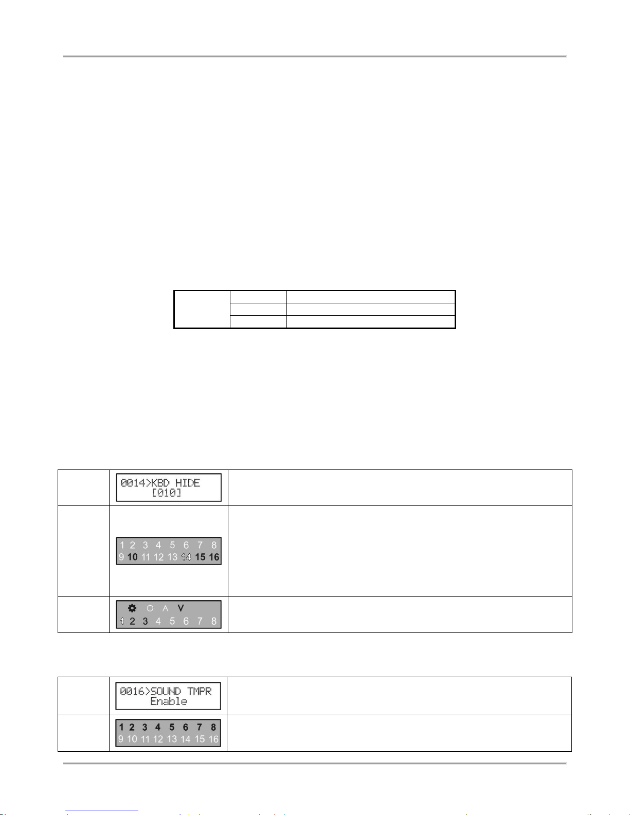
CONF.
TIMER
ADDRESS
0014
OPERATION
014
TEXT MENU
2. SETTINGS – 04. CONF. TIMER
“Confidential Mode” Timer
This parameter is common for all keyboards. Enter a time from 10 to 180 seconds.
The “Confidential mode” is a special mode for hiding the information for the activated zones and used
areas. The mode is assigned for every keyboard at address 8xx2 (Device Options), with enabling the
options 3 and 4 – see the detailed description in Menu 8. Peripheral Devices.
Parameter by default: 010 (10 seconds)
AC DELAY
ADDRESS
0015
OPERATION
015
TEXT MENU
2. SETTINGS – 05.AC DELAY
AC Power Supply Failure Indication Delay
Programming of time for delay indication in case of 220 VAC power supply failure.
Enter a time from 0 to 255 minutes. The set time is confirmed with ENTER button.
In case of using a LED keyboard, you can review the set time with arrow buttons. The blinking zone
number indicates a programming mode for that value. A permanently lit zone number shows the
current set value (10 means 0). To change it, press other digit button – the cursor automatically
moves on the next value to the right.
If by mistake the installer enters bigger time than maximal of 255 minutes, the keyboard will reject the
entered value and will display the maximal possible one.
Parameter by default: 030 (30 minutes)
SOUND
TMPR
ADDRESS
0016
OPERATION
016
TEXT MENU
2. SETTINGS – 06.SOUND TMPR
Programming of Silent/ Audible Sound TAMPER signal
Programming of silent or audible TAMPER event (a zone TAMPER type or physical tamper-switch is
open) when the system is disarmed.
At this address, you set the parameter as:
DISABLE
Silent
TAMPER
In case of a TAMPER event:
- The LED indication is activated;
- TAMPER Outputs type are activated (the ALARM and SIREN outputs type are not
activated);
- A TAMPER alarm message is send to monitoring station (via PSTN, GPRS or LAN).
ENABLE
Audible
TAMPER
In case of a TAMPER event:
- The LED indication and the internal buzzer of the keyboards are activated and can
be cleared only after entering of valid user code;
- A TAMPER alarm signal activated (activation of outputs type ALARM, SIREN and
ТАМPER);
- A TAMPER alarm message is send to monitoring station (via PSTN, GPRS or LAN).
Programming this address will not affect the TAMPER signal when the system is in armed mode.
Programming this address will affect the performance of the programmable outputs type SIREN,
ALARM and TAMPER, the LED and sound indication of the keyboards and the digital communicator
when the system is disarmed.
Every pressing of a digital button alternatively changes the enabled / disabled status. The display
indication is shown in the table.
Parameter by default: ENABLE (audible TAMPER)
Page 24
Eclipse 8/ 16/ 32 Series - Engineer Programming Manual
24
ALARM
DELAY
ADDRESS
0017
OPERATION
017
TEXT MENU
2. SETTINGS – 07.ALARM DELAY
Programming of alarm message delay to monitoring station and siren activation with 30
seconds or until the programmed entry time is over (the smaller value of both times is taken) in case
a zone, out of the entry route, is activated.
At this address, you set the parameter as:
DISABLE
The delay is disabled – the system immediately sends an alarm message to the
monitoring station (via PSTN, GPRS or LAN) and activates the siren outputs.
ENABLE
30 seconds delay is enabled – the system will delay sending of alarm message and
siren outputs activation with 30 seconds when in arming mode Entry-Exit, Follow or
Instant type zones are activated.
The system will wait 30 seconds for entering of valid user code to disarm or until the
programmed entry time is over (the smaller value of both times is taken). If a valid
user code is not entered in that period, the system will send an alarm message to the
monitoring station and will activate the siren outputs.
Parameter by default: DISABLE
WALK TEST
ADDRESS
0020
OPERATION
020
TEXT MENU
1. MAINTENANCE – 2. WALK TEST
Enables functional test of zones. The respective light-emitting diode (LED keyboard) or a number of
a zone (LCD keyboard), blinks while the zone is activated (open) in this mode. During the test, every
zone activation is accompanied with "Chime" sound signal and with continuous sound for "reject" –
open TAMPER zone.
PGM TEST
ADDRESS
0021
OPERATION
021
TEXT MENU
1. MAINTENANCE – 3. PGM TEST
Serviceability tests of programmable outputs are carried out at the address.
There are two fields available in the LCD keyboard display. The installer enters the number of PGM
for test, and the PGM status ON (PGM activation)/ OFF (PGM deactivation).
During the test is set low or high output level:
OFF
(NO) The output is switch on high level: +12 V
ON
(NC) The output is switch on low level: 0 V
Important notes
In operation with LED 8/ 16A, after entering at the address the system automatically displays the
value setting mode.
ECLIPSE 8/ 16 (PGM 1-5)
ECLIPSE 32 (PGM 01-32)
The blinking digit performs the value for editing, and a lighting on button displays the current set
value. To change the value press a digit button – the cursor moves on the next zone number and so
on.
ECLIPSE 32: The zone number 3 performs the PGM state – ON (all buttons light on) and OFF (all
buttons light off). The state is alternatively changed with pressing a random digit button.
Page 25
Eclipse 8/ 16/ 32 Series - Engineer Programming Manual
25
COMM TEST
ADDRESS
0023
OPERATION
023
TEXT MENU
1. MAINTENANCE – 4. COMM TEST
The performance of the communicator can be directly monitored at this address.
Before starting the monitoring of the communicator performance, you have to enter a telephone
number at ADDRESS 6010.
The FULL Arm ( / ) button causes test transmission from the communicator to the central
station and from the voice dialer to assigned telephone numbers. The 0 button aborts any running
communication and deletes the queue of events to be sent.
The meaning of the symbols is given below, as the "active state" means permanent lighting of the
LEDs (LED keyboard) or step number (LCD keyboard).
After communication has been successfully completed, the keyboard emits a sound signal. The
CLEAR button exits Address 0023.
Button
Action
1
Dialing the telephone number.
2
Waiting for „handshake” signal from the monitoring station.
3
Transmitting data to the monitoring station.
4
Waiting for confirmation signal from the monitoring station, ‘kissoff’ signal.
5
Communication process has been completed and all data has been successfully
transmitted to the central station.
HWR RESET
ADDRESS
0030
OPERATION
030
TEXT MENU
2. SETTINGS – 08.HWR RESET
Hardware Reset Enable
Specialized service is required where the hardware RESET is disabled and the engineer code is
obscure.
The parameter status can be changed with pressing of random button of the keyboard.
At this address, you set the parameter as:
DISABLE
The hardware reset is not allowed.
ENABLE
The hardware reset is allowed.
Parameter by default: ENABLE
SELECT
MENU
ADDRESS
0031
OPERATION
031
TEXT MENU
2. SETTINGS – 09.PART DEFAULT
Partial software reset of a programming menu.
The engineer can make a partial reset and to restore the system parameters for a certain
programming menu at this address. Enter a number from 0 to 8 (except 7) and press ENTER. The
system will ask for a confirmation password – enter in sequence the service code 123456 and press
ENTER. The system will restore the default settings only for the chosen menu.
Page 26
Eclipse 8/ 16/ 32 Series - Engineer Programming Manual
26
To restore the default parameters for a menu press the respective digit button (in operation with 4and 3-digit addresses):
Button 0 – Menu 0. General Settings
Button 1 – Menu 1. Users
Button 2 – Menu 2. Zones
Button 3 – Menu 3. PGM Outputs
Button 4 – Menu 4. Areas
Button 5 – Menu 5. Time Slots
Button 6 – Menu 6. Communicator
Button 8 – Menu 8. Peripheral Devices
RESET MNG
ADDRESS
0032
OPERATION
032
TEXT MENU
2. SETTINGS – 10. RESET MNG
Main Manager Code Reset
Restoration of the default main manager code (User 01). Buttons 1, 2, 3, 4, 5, 6 are pressed in
succession and confirmed with the ENTER button.
The system restores the default 0000 manager user code.
Default Main Manager Code: 0000
LOG EVENT
ADDRESS
0040
OPERATION
040
TEXT MENU
1. MAINTENANCE – 1. VIEW LOG
Memory LOG Events
Review of memory LOG events in the system.
The memory LOG file is with different capacity: 256 (ECLIPSE 8) and 1024 (ECLIPSE 16/ 32)
system events. The events recorded in the power independent memory of the control panel can be
traced with the help of the arrows. The first event which is visualized is the last recorded.
Use the digit button 2 to review some additional information for the event such as user, zone or area
number.
In case of using a LED keyboard to review the memory LOG file, keep in mind that the visualization
of the memory events is presented with hexadecimal values. For correct reading the information use
the table for the events in the APPENDIX 2.
SYSTEM
NAME
ADDRESS
0050
OPERATION
050
TEXT MENU
2. SETTINGS – 11. SYSTEM NAME
Programming of the System Name
The engineer can enter a new system name at this address. The name has to be up 16 symbols –
letters (small and capital), digits and special symbols, including spaces.
The letters can be entered directly by the digit buttons. The cursor moves automatically to the right
after choosing of letter or digit, or may be moved manually by the arrows. To enter a digit press the
respective button and hold it for 2-3 seconds. See also item 2.8. Entering text for LCD Keyboard.
Confirm the new system name with ENTER button.
Default system name: << TTE >>
Page 27
Eclipse 8/ 16/ 32 Series - Engineer Programming Manual
27
TIME
ADDRESS
0051
OPERATION
051
TEXT MENU
2. SETTINGS – 12. TIME
Setting the built-in clock
The engineer sets at this address the current time (HH:MM).
Default setting: [00:00]
DATE
ADDRESS
0052
OPERATION
052
TEXT MENU
2. SETTINGS – 13. DATE
Setting the system date
The engineer sets at this address the current date (DD/MM/YY).
Default setting: [01/01/12]
MENU STYLE
ADDRESS
0097
OPERATION
097
TEXT MENU
2. SETTINGS – 14. MENU STYLE
Programming Menu Style
The engineer sets the programming menu style at this address. Choose the number of the menu
style according your preference, as:
1
Programming with 4-digit address menus. In LCD keyboards with the 4-digit address is
available also and a short text description. This programming menu style is available in
operation with all keyboard models.
2
Programming with 3-digit operation menus. In LCD keyboards with the 3-digit address is
available also and a short text description. This programming menu style is available in
operation with all keyboard models.
3
Programming with text menus. The text menus are available as tree-structure. This menu
programming style is available only in operation with LCD клавиатури.
If you choose to operate with text menus, they will be available only with LCD keyboards in the
system, while the engineer programming via the LED keyboards in the system will the available with
4-digit address menus.
Default setting: [3]
SW
REVISION
ADDRESS
0098
OPERATION
098
TEXT MENU
1. MAINTENANCE – 5. SW REVISION
The engineer can review the current software revision of the control panel at this address.
Page 28
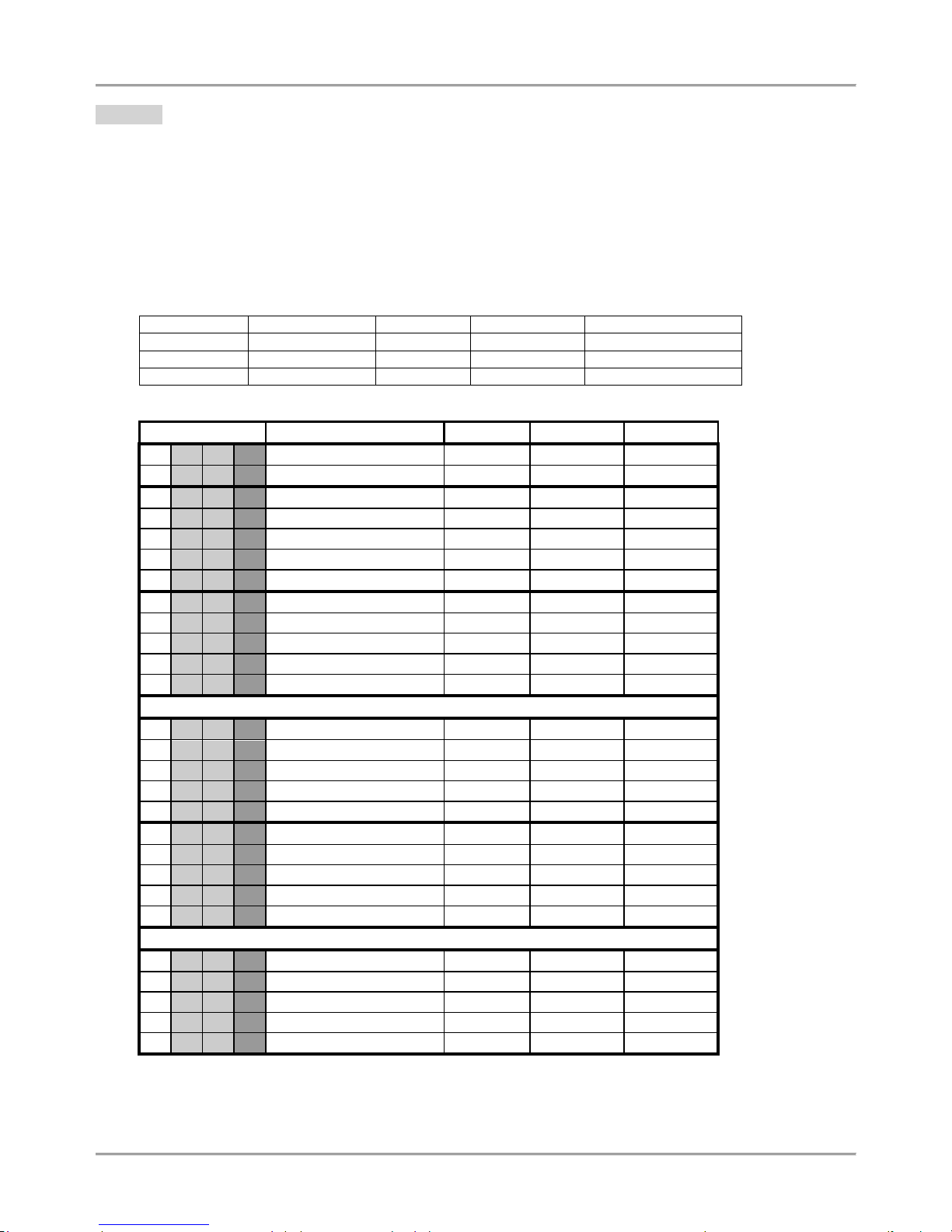
Eclipse 8/ 16/ 32 Series - Engineer Programming Manual
28
1. Users
In “USERS” menu, the engineer programs some parameters and settings for the managers and users in the system.
Some of the addresses are available for programming only with LCD keyboard!
Attention: The USER 01 is the Chief Manager of the system. The Chief Manager has full rights to operate with
manager’s programming menus. The Chief Manager rights cannot be changes. All other users in the system are with
freely programmable rights.
The manager has extended rights in the system and can assign user codes and rights, and also to set the date and
time, and adjust some options of the keyboards – setting of the buzzer level, brightness, etc.
Every regular user in the system can change its own code only, while the Manager can change all other regular users’
codes. A Manager in the system cannot change other Manager’s code (available for ECLIPSE 32).
ECLIPSE Control Panels Series – User capability:
Control panel
Max. user codes
Code digits
Chief Manager
Max. Manager codes
ECLIPSE 8
8 4 1
1
ECLIPSE 16
32 4 1
1
ECLIPSE 32
64
4/6 1 Up to 64
Quick table for 1. Users Programming Menu
Address Number
Programming parameter
ECLIPSE 8
ECLIPSE 16
ECLIPSE 32
1 0 0 0 Code Length
1 0 0 1 Code clone
1 0 1 0 User 01 Options
1 0 1 1 User 01 Areas
1 0 1 2 User 01 Name
1 0 1 3 User 01 Proxy
1 0 1 4 User 01 Time Slot
1 0 2 0 User 02 Options
1 0 2 1 User 02 Areas
1 0 2 2 User 02 Name
1 0 2 3 User 02 Proxy
1 0 2 4 User 02 Time Slot
…
1 0 8 0 User 08 Options
1 0 8 1 User 08 Areas
1 0 8 2 User 08 Name
1 0 8 3 User 08 Proxy
1 0 8 4 User 08 Time Slot
1 0 9 0 User 09 Options
1 0 9 1 User 09 Areas
1 0 9 2 User 09 Name
1 0 9 3 User 09 Proxy
1 0 9 4 User 09 Time Slot
…
1 6 4 0 User 64 Options
1 6 4 1 User 64 Areas
1 6 4 2 User 64 Name
1 6 4 3 User 64 Proxy
1 6 4 4 User 64 Time Slot
Page 29
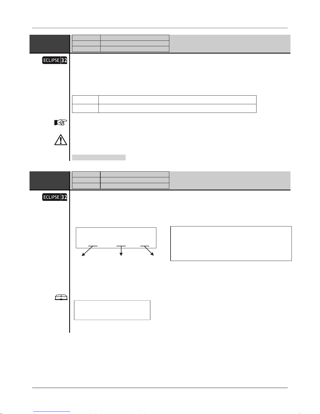
Eclipse 8/ 16/ 32 Series - Engineer Programming Manual
29
CODE
LENGTH
ADDRESS
1000
OPERATION
100
TEXT MENU
3. CODES – 3. CODE LENGTH
Code digits length
The system allows using 4 and 6 digits codes: engineer, maintenance and users.
Every pressing of a digital button or the arrows alternatively changes the digits number. The set
parameter is confirmed with ENTER button.
At this address is assigned:
4 digits
The Engineer, maintenance and users are using 4 digit access codes.
6 digits
The Engineer, maintenance and users are using 6 digit access codes.
When switching from 4- to 6-digits code, the digits 00 will automatically be added at the end. For
example, the 4-digits code 1234 will become 123400.
When changing over from 6- to 4-digits code, only the first four figures in the 4-digits code
will remain valid. For example, the 6-digits code 123456 will become 1234. Due to risk of
coincidence of codes, changing over from 6- to 4-digits code IS NOT RECOMMENDED!
Default setting: 4 digits
CODE
CLONE
ADDRESS
1001
OPERATION
101
TEXT MENU
3. CODES – 4. CODE CLONE
User Codes Cloning
This is an address for coping (cloning) of attributes, rights, areas, time slots and control options for
card readers for user codes. The user access codes are not automatically cloned – they have to be
assigned for every one user separately from the Manager’s programming menu.
The information for cloning is set in three digit sections with the following meaning:
1001>CODE CLONE
[01]> [10] [20]
Source
Code
First Code
to clone
Last Code
to clone
It is possible to clone only serial number of codes. If it is necessary to clone parameters to one user
code only, then enter 00 or the same user code in the “Last Code to clone” field. Press the ENTER
button to start the cloning procedure.
Example:
1001>CODE CLONE
[03]> [04] [10]
The source code is the User Code 03 and its parameters will be programmed in the settings of User
Codes from 04 to 10 inclusive.
Source Code – This is the source code which parameters
will be copied.
First Code to clone – This is the first code number to
which the parameters of the source code will be assigned.
Last Code to clone – This is the last code number to
which the parameters of the source code will be assigned.
Page 30

Eclipse 8/ 16/ 32 Series - Engineer Programming Manual
30
U1 OPTIONS
ADDRESS
1010
OPERATION
110+01
TEXT MENU
3. CODES – 1. USERS – 01. USER – 1. OPTIONS
User 01 Operation rights
User code 01 is the Chief Manager in the system and always has full rights for operation and
programming of the system, which cannot be changed or erased!
The following options are available for User Code 01:
1. DISARM ENABLE
The user has the right to disarm the system.
2. PART ARM ENABLE
Partial arming
The user has the right to perform partial arming of the system – STAY
or SLEEP Arming type.
3. BYPASS ENABLE
Zone Bypassing
The user has the right to perform zone bypassing in system.
4. PROGRAM ENABLE
The user has the right to change its own access code, to review the
memory LOG file, to bypass zones and other options.
5. N.A
6. N.A
7. N.A
8. MANAGER ENABLE
MANAGER in the
system
The user code is Manager in the system – it has the right to change
other user access codes and to access the Manager’s programming
menus.
Default settings: All rights are enabled
U1 AREAS
ADDRESS
1011
OPERATION
111+01
TEXT MENU
3. CODES – 1. USERS – 01. USER – 2. AREAS
Association of Areas to User 01
The engineer associates areas to User code 01 at this address. The User can operate (arm, disarm,
bypass zones) only with area numbers associated to its code. One or several areas can be
associated to the user code. To select area, press the corresponding to its number digit button. Next
pressing of the same button will deselect the same area. The final configuration is confirmed with
ENTER button.
The User code 01 is always associated to at least one area number. All other user codes will
be inactive if there are no associated areas to them, irrespective of the assigned rights at the
previous!
It is possible the associated area numbers to the control device (keyboard or card reader) to be
different according to the area numbers associated to User code 01. In this case, the user code or
proximity card can operate only in the common areas for the device and the code. For example, if to
the user code all areas are associated in the system, and the associated to the control device areas
are 1, 2, 3 and 4, then and the user code can operate only with them.
To associate all areas to the user press button “0” – the button alternatively switches over all
enabled / all disabled state.
Default setting: All Areas
Page 31

Eclipse 8/ 16/ 32 Series - Engineer Programming Manual
31
U1 NAME
ADDRESS
1012
OPERATION
112+01
TEXT MENU
3. CODES – 1. USERS – 01. USER – 3. NAME
Programming of the User 01 Name
The engineer can enter a new name for User 01 at this address. The name has to be up 16 symbols
– letters (small and capital), digits and special symbols, including spaces.
The letters can be entered directly by the digit buttons. The cursor moves automatically to the right
after choosing of letter or digit, or may be moved manually by the arrows. To enter a digit, press the
respective button and hold it for 2-3 seconds. See also item 2.8. Entering text for LCD Keyboard.
Confirm the new user name with ENTER button.
Default name: User 01
U1 PROXY
ADDRESS
1013
OPERATION
113+01
TEXT MENU
3. CODES – 1. USERS – 01. USER – 4. PROXY
Assigning rights for operation with proximity card for User code 01
The engineer assigns rights to the proximity card for operation (arm, disarm) with User code 01. The
settings at this address include operation with a built-in in a keyboard proxy reader only.
According the settings at the address the user code can perform disarming and/ or arming the
system.
The arming options are set as a combination of options 2 and 3.
To enable an option press the digit button corresponding to its number. The next pressing of the
same button will deselect it.
The enabled option is indicated as digit on the LCD display or lighting on zone number on the LED
display. For LED 8/ 16A keyboards the set option is indicated with a lighting on digit button.
The set options are confirmed with ENTER button.
The following options are assigned at this address:
1. DISARM
Authorization for the user code to Disarm the site with a proximity card.
DISARM ENABLE (1) – The user code can disarm the site with a proximity
card.
DISARM DISABLE () – The user code cannot disarm the site with a
proximity card.
2. Proxy card
ARMING options
The options 2 and 3 are assigned in a certain combination to set the
arming mode when using a proximity card:
2
3
Arming type
Arming is disabled
3
Full Arming mode
2 Stay Arming mode
2 3 Sleep Arming mode
3. Proxy card
ARMING options
Example:
1013>CD1_PROXY
[1*3_____]
User code 01 can disarm the associated to it areas and to realize Full Arming when using a
proximity card for system management.
Default settings: DISARM ENABLE; SLEEP ARM
Page 32

Eclipse 8/ 16/ 32 Series - Engineer Programming Manual
32
U1 T.SLOT
ADDRESS
1014
OPERATION
114+01
TEXT MENU
3. CODES – 1. USERS – 01. USER – 5.TIMESLOT
Programming of time slot for User code 01
An access code timeslot is set.
The valid timeslot numbers are from 1 to 8. If the selected access code is not to be restricted by a
timeslot, enter 0.
Use the digit buttons to enter the timeslot number. The entered number is confirmed with ENTER.
For programming of timeslots, see for details Menu. 5 Timeslot Programming.
Default settings: 0
User codes form 02 to 08/ 32/ 64 are programmed in an analogical way.
The rights of User codes set at addresses 1хх0 (110 + хх), where “xx” is a user number from 02 to 08/ 32/ 64, can be
enabled or disabled according the system settings:
Uxx
OPTIONS
ADDRESS
1xx0
OPERATION
110+xx
TEXT MENU
3. CODES – 1. USERS – xx. USER – 1. OPTIONS
User xx Operation rights
The following options are assigned for the User xx Code:
1. DISARM
DISARMING the site:
DISARM ENABLE (1) – the user code has right to disarm the site
DISARM DISABLE () – the user code has not right to disarm the site
2. PART ARM
Partial arming
Partial arming STAY or SLEEP type:
PART ARM ENABLE (2) – the user code has right to realize partial arming
STAY or SLEEP type
PART ARM DISABLE () – the user code has not right to realize partial arming
STAY or SLEEP type
3. BYPASS
Zone
Bypassing
Bypassing zones in the site:
BYPASS ENABLE (3) – the user code has right to bypass zones
BYPASS DISABLE () – the user code has not right to bypass zones
4. PROGRAM
Programming – change own code, reviewing the memory log, enabling/
disabling the “chime” sound signalization, zone bypassing:
PROGRAM ENABLE (4) – the user code can realize programming
PROGRAM DISABLE () - the user code cannot realize programming
5. N.A
6. N.A
7. N.A
8. MANAGER
MANAGER in
the system
Manager in the system – can program user codes and rights in the system,
reviewing the memory log, zone bypassing:
MANAGER ENABLE (8) – the code has Manager rights
MANAGER DISABLE () – the code has not Manager rights
When the option 8. MANAGER is enabled, it is obligatory to enable and option 4. PROGRAM!
To disable/ enable all user operation rights press button “0” – the button alternatively switches over
all enabled / all disabled state.
Default settings:
User codes
ECLIPSE 8
ECLIPSE 16
ECLIPSE 32
01
1, 2, 3, 4
1, 2, 3, 4
1, 2, 3, 4, 8
02-08
1, 2
1, 2
1, 2
09-32
33-64
Page 33

Eclipse 8/ 16/ 32 Series - Engineer Programming Manual
33
2. Zones
In “ZONES” menu, the engineer programs some parameters and settings for the zones in the system.
Some of the addresses are available for programming only with LCD keyboard!
ECLIPSE Control Panels Series – Zones capability:
Control panel
Max. Zone
Connection styles
Doubling zones
ECLIPSE 8 8 5
ECLIPSE 16
16
5
ECLIPSE 32
32
9
Quick table for 2. Zones Programming Menu
Address Number
Programming parameter
ECLIPSE 8
ECLIPSE 16
ECLIPSE 32
2 0 0 0 Zone Wiring
2 0 0 1 Zone AutoBypass
2 0 0 2 Zone Instant
2 0 0 3 Zone Pulse Count
2 0 0 4 Zone Time Pulse Count
2 0 0 5 Zone Cloning
2 0 1 0 Zone 01 Attach
2 0 1 1 Zone 01 Type
2 0 1 2 Zone 01 Areas
2 0 1 4 Zone 01 Attributes 1
2 0 1 5 Zone 01 Attributes 2
2 0 1 6 Zone 01 Key switch
2 0 1 7 Zone 01 AUX Attributes
2 0 1 8 Zone 01 Name
2 0 1 9 Zone 01 Line Resistance
…
2 1 6 0 Zone 16 Attach
2 1 6 1 Zone 16 Type
2 1 6 2 Zone 16 Areas
2 1 6 4 Zone 16 Attributes 1
2 1 6 5 Zone 16 Attributes 2
2 1 6 6 Zone 16 Key switch
2 1 6 7 Zone 16 AUX Attributes
2 1 6 8 Zone 16 Name
2 1 6 9 Zone 16 Line Resistance
…
2 3 2 0 Zone 32 Attach
2 3 2 1 Zone 32 Type
2 3 2 2 Zone 32 Areas
2 3 2 4 Zone 32 Attributes 1
2 3 2 5 Zone 32 Attributes 2
2 3 2 6 Zone 32 Key switch
2 3 2 7 Zone 32 AUX Attributes
2 3 2 8 Zone 32 Name
2 3 2 9 Zone 32 Line Resistance
Page 34

Eclipse 8/ 16/ 32 Series - Engineer Programming Manual
34
Z WIRING
ADDRESS
2000
OPERATION
200
TEXT MENU
4. INPUTS – 1. WIRING
Zone connection styles
Set connection style for zones – it is common for all used zones in the system, including the
keyboard zones. Choose a number from according the realized zone connection.
ECLIPSE 8 supports only single connection in the zones.
ECLIPSE 16 supports only single connection in the zones.
ECLIPSE 32 supports both single and doubling connection in the zones.
Connection Style Diagrams:
Default connection style: [2]
Page 35

Eclipse 8/ 16/ 32 Series - Engineer Programming Manual
35
Z ABYPASS
ADDRESS
2001
OPERATION
201
TEXT MENU
4. INPUTS – 2. AUTO BYPASS
Number of Activations per Zone for Auto Bypass Mode
The number of activations (number of alarm cycles from 1 to 9) in one arm mode, which have to be
accomplished for a zone with an assigned AUTOBYPASS parameter, are entered at this address.
After reaching the set number of activations, the respective zone will be automatically bypassed.
When disarmed and then again armed the respective zone will remain armed.
The 0 value disables the Zone AutoBypass mode even if there is set option “1. AUTOBYPASS” at
address 2хх4, where хх is the zone number.
Default setting: [6]
Z INSTANT
ADDRESS
2002
OPERATION
202
TEXT MENU
4. INPUTS – 3. INSTANT
Enabling of Instant type zones
The engineer can enable or disable the intrusion of instant type zones during exit time running at
this address. Enabling this operating mode would reduce the probability for a false alarm signal to be
triggered off by mistake on behalf of the user.
The parameter status can be changed with pressing of random button of the keyboard.
At this address, you set the parameter as:
DISABLE
Disabled intrusion in INSTANT type zones during exit time.
ENABLE
Enables intrusion in INSTANT type zones during exit time.
Default setting: DISABLE
Z PCOUNT
ADDRESS
2003
OPERATION
203
TEXT MENU
4. INPUTS – 4. PULSE COUNT – 1. PULSES
Number of activations in pulse count mode
The number of pulses in Pulse Count mode is assigned at this address.
Values between 1 and 9 pulses can be entered here.
The 0 value blocks the Pulse Count mode and zone can then function with the regular time for
detecting activation.
The working algorithm for zone 4 in Pulse Count mode is described at ADDRESS 2015 – Zone 01
Attributes 2.
Default setting: [0]
Z TPCOUNT
ADDRESS
2004
OPERATION
204
TEXT MENU
4. INPUTS – 4. PULSE COUNT – 2. TIMEOUT
Time for zones in pulse count mode
A time for zones in Pulse Count mode is assigned at this address. Enter a time in interval 0-255 sec.
See also ADDRESS 2015 - Zone 01 Attributes 2 for details.
Default setting: [000]
Page 36

Eclipse 8/ 16/ 32 Series - Engineer Programming Manual
36
Z CLONE
ADDRESS
2005
OPERATION
205
TEXT MENU
4. INPUTS – 6. ZONE CLONE
Zone Cloning
This is an address for coping (cloning) of attributes, rights, areas and time slots from one to several
zones.
The information for cloning is set in three digit sections with the following meaning:
2005>Z CLONE
[01]> [02] [05]
Source
Zone
FirstZone
to clone
Last Zone
to clone
It is possible to clone only serial number of zones. If it is necessary to clone parameters to one zone
only, then in the “Last zone to clone” field enter 00 or the same zone. Press the ENTER button to
start the cloning procedure.
Example:
2005>Z CLONE
[02]> [03] [05]
The source zone is Zone 02 and its parameters will be programmed in the settings of zone numbers
from 03 to 05 inclusive.
Z1 ATTACH
ADDRESS
2010
OPERATION
210 + 01
TEXT MENU
4. INPUTS – 5. ZONES – 01. ZONE – 1. ATTACH
Number of device and Zone 01 input number
The installer can review the device number and its input/ output number associated to the zone.
In the maximal configuration of ECLIPSE 16 can be attached and programmed up to 16 zone
numbers. In the maximal configuration of ECLIPSE 32 can be attached and programmed up to 32
zone numbers – that depends on the used connection style and addressed devices.
Zones from 01 to 08 are the on board zones and they are fixed at ADDRESSES 2010 to 2080. The
contents of ADDRESSES 2010 – 2080 cannot be changed. The first digit performs the ID number of
the device and the second performs the physical input attached to the zone number. Zones 01 – 08
are the physical inputs placed on the control panel so they are displayed as:
Zone 01: [1] [1] – The zone is attached to the 1st input of device 01 (the control panel);
Zone 02: [1] [2] – The zone is attached to the 2nd input of device 01 (the control panel), and so on.
Zones from 09 to 32 can be on board zone inputs on zone expander or keyboard, or logical when
using doubling zone connection in the system (connection style 6-9 – see the correspondence in
APPENDIX 1). The contents of ADDRESSES 2090 – 2320 are freely programmable according the
system configuration – see the examples after this address description.
In case the PGM4 is programmed as fire zone (ADDRESS 3000) that zone will be attached to
device 01 (the control panel) as zone number 99. The installer can attach that fire zone to anyone
free zone as at the ADDRESS 2xx0 programs [01] for device and [99] for input/ zone number.
Setting of device and input/ zone number for a keyboard
All ECLIPSE Series keyboards have an additional zone input appropriate for connecting of magnetic
contacts or other devices. The keyboard zone takes all common setting for zones. To add the
keyboard zone to the system configuration you must first to attach it to a zone address and device
ID number – the device in this case is the keyboard. According to the system configuration, the
keyboard zone can be attached to any free zone at address 2xx0, where xx is a zone number
from 09 to 32.
Source Zone – This is the source zone which parameters
will be copied.
First Zone to clone – This is the first zone number to which
the parameters of the source zone will be assigned.
Last Zone to clone – This is the last zone number to which
the parameters of the source zone will be assigned.
Page 37

Eclipse 8/ 16/ 32 Series - Engineer Programming Manual
37
Example 1. At address 8020 (Device 02) to the control panel is enrolled a keyboard with one on
board zone input. Choose a free zone in the system configuration, number 15 for example, where to
attach the keyboard zone. Enter in the engineer programming menu, type address 2150, enter in
sequence number of device 02, and input number 01. The screen displays:
2150>Z15 ATTACH
[02] [01]
Example 2. At address 8100 (Device 10) to the control panel is enrolled a zone expander with 8 on
board zone inputs. Choose a free zone in the system configuration, number 20 for example, where
to attach the first zone of the expander. Enter in the engineer programming menu, type address
2200, enter in sequence number of device 10, and input number 01. The screen displays:
2200>Z20 ATTACH
[10] [01]
To use the second zone input of the same expander you have to attach it to the next free zone in the
system configuration – for example 21. Then at address 2210, you should enter in sequence
number of device 10 and input number 02. In analogical way proceed with the other zone inputs of
the expander to attach them to free zones in the system configuration.
Z1 TYPE
ADDRESS
2011
OPERATION
211 + 01
TEXT MENU
4. INPUTS – 5.ZONES – 01. ZONE – 2. TYPE
The type of ZONE 01 is set at this address.
Only one type can be selected for a zone!
Press the digital button, which corresponds to the number of the desired type.
No
Type
Description
0
UNUSED
The zone is not used.
1
ENTRY/ EXIT
Entry- Exit zone.
Provides time to arm and disarm the site. After arming, the detector,
which was triggered off in this zone, will not sound an alarm until the
programmed EXIT TIME expires for the Area (or Areas) to which the
zone is attached.
No violation of the zone when in armed mode will sound an alarm before
the programmed ENTRY TIME expires for the Area (or Areas) to which
the zone is attached.
A sound signal is activated from the keyboard buzzer during entry and
exit time.
In SLEEP ARMING mode, the entry-exit type zones become instant and
no entry or exit time starts running when violation in the zone accures –
the programmable ALARM and SIREN type outputs, and the
communicator are activated at once.
2
FOLLOW
Follow zone.
An alarm zone which is active only when the site is armed in Full and
Stay arming. The zone operates instantaneously and activates the
programmable ALARM and SIREN type outputs, and the communicator.
Activating the zone during entry or exit time does not cause an alarm
event.
The entry time will start running if the follow type zone is activated while
the system is in SLEEP ARMING mode.
When the system is disarmed, the activation of a zone is indicated by
blinking of the respective light-emitting diode for the zone (LED
keyboards) or displayed zone name and number (LCD
keyboards) for the time that the zone remains open (The
displayed mode can be disabled for Eclipse 32 control panel at the
Page 38

Eclipse 8/ 16/ 32 Series - Engineer Programming Manual
38
address 8xx2 – keyboard options).
3
INSTANT
Instant zone.
An alarm zone which is active only when the site is armed. The zone
operates instantaneously and activates the programmable ALARM and
SIREN type outputs, and the communicator.
When the system is disarmed, the activation of the zone is indicated
with active zone number for the time that the zone remains open.
An INSTANT type zone can be violated during Exit time running if at
ADDRESS 2002 (OPERATION 202) the "Enabled Instant" parameter is
enabled.
4
FIRE
24 – hour fire type zone.
Allows connecting 12V fire detectors to the system. These should avail
of a normally closed relay output in inactive status. Any activation of the
zone will trigger off SIREN type outputs, the programmable FIRE type
outputs and the digital communicator. The 24-hour fire type zones are
with the highest priority in the system and are indicated at first place.
5
PANIC
24 – hour panic type zone.
Activating the zone will trigger off the PANIC type outputs, the SIREN
type outputs and the digital communicator. The PANIC type zones
operate in “Silent panic” mode when “3. Report only” option is set at
address 2хх5 – Setting of Attributes 2, where хх is the zone number. In
this case, the zone activation is not indicated on the keyboards (sound
or LED indication), and only the digital communicator will send an alarm
message to the monitoring station.
After entering of valid user code the MEMORY button (LED) lights on
together with the LED/ number of the activated zone and area.
The indication of the memory can be deleted by entering a valid user
code, a manager code or during the next arming.
6
TAMPER
24 – hour tamper type zone.
Activating this zone type triggers off the SIREN output, the
programmable TAMPER type outputs and the station communicator.
When the system is disarmed and the TAMPER type output is
programmed as “DISABLE” at ADDRESS 0016 (OPERATION 016) –
Sound TAMPER, the activation of the zone will not be indicated on the
keyboards (sound or display indication), and only the digital
communicator will send an alarm message to the monitoring station. In
case the TAMPER type output is programmed as “ENABLED” at
address 0016, the activation of the zone will cause a sound signal from
the keyboards in DISARM mode.
7
MEDICAL
24 – hour medical type zone.
Assigning this zone type will set the programmable MEDICAL and
SIREN type outputs active and will start the communicator.
The number of activated zone is displayed irrespective of the system
status.
The MEDICAL type zones operate in “Silent Panic” mode when the
attribute “3. Report only” is set at address 2хх5 – Setting of Additional
attributes, where “хх” is the zone number. In this case, the activation of
the zone will not be indicated on the keyboards (sound or display
indication), and only the digital communicator will send an alarm
message to the monitoring station.
After entering of valid user code the MEMORY button (LED) lights on
together with the LED/ number of the activated zone and area.
The indication of the memory can be deleted by entering a valid user
code, a manager code or during the next arming.
8
KEY-SWITCH
Key-switch type, 24–hour alarm zone.
When this zone type is assigned, the respective panel input is used to
transmit the arming and disarming signal with the help of a key-switch.
The installer sets the type of the zone activation:
• With an impulse (PULSE attribute is set at ADDRESS 2016);
• Reaction of open or in normal operation mode zone (LATCH
attribute is set at ADDRESS 2016).
Page 39

Eclipse 8/ 16/ 32 Series - Engineer Programming Manual
39
Arming is only possible in Full Arm mode. Arming will be anticipated
only when the system is ready - all zones are inactive.
The additional attributes for key-switch type zone is programmed at
address 2xx6 (OPERATION 216 + 01), where “xx” is the number of the
zone.
9
AUXILIARY
24-hour auxiliary type zone
When this zone type is assigned, respectively a number of AUX attribute
should be programmed at ADDRESS 2xx7, where xx is the number of
the zone (OPERATION 217 + xx).
Default setting:
Type
Zone number
ECLIPSE 8
ECLIPSE 16
ECLIPSE 32
01 2 1 1 02 3 2 2 03 3 0 0 04 3 0 0 05 5 0 0 06 6 0 0 07 1 0 0 08 1 0
0
09-16 0 0 17-32
0
Z1 AREAS
ADDRESS
2012
OPERATION
212 + 01
TEXT MENU
4. INPUTS – 5. ZONES – 01. ZONE – 3. AREAS
Association of Areas to Zone 01
According the system configuration the engineer associates one or several AREA numbers for
operation with ZONE 01. To select an AREA press the digit button corresponding to its number. The
next pressing of the same button will deselect the AREA.
To select all areas press button “0” – the button alternatively switches over all enabled / all disabled
state.
The zone will be inactive if there are no associated areas to it!
Default setting: AREA 1
Z1 ATTR 1
ADDRESS
2014
OPERATION
214 + 01
TEXT MENU
4. INPUTS – 5. ZONES – 01. ZONE – 4. OPTIONS 1
Setting of Main Attributes for Zone 01
According the system configuration the engineer sets a range of main attributes for ZONE 01. More
than one attribute can be assign to the zone but it depends on its type. To select an attribute press
the digit button corresponding to its number. The next pressing of the same button will deselect the
attribute.
To select all attributes press button “0” – the button alternatively switches over all enabled / all
disabled state.
The Attributes from 1 to 7 can be assigned only for certain zone types – see the table below
for zone type compatibility! Some of the Attributes are not available in ECLIPSE 8/ 16 control
panel.
The following Attributes are available for setting at this address:
Page 40

Eclipse 8/ 16/ 32 Series - Engineer Programming Manual
40
No
Attribute
Description
1
Auto BYPASS
Authorization for automatic Bypassing the zone after reaching the number
of activations per armed mode as set at address 2001 (OPERATION 201)
for an arming mode.
2
BYPASS
Authorization to Bypass a zone. Assigning this attribute to the respective
zone will authorize bypass of the zone on behalf of the system user or
manager.
3
Stay ARM
The zone is not going to be armed in the STAY mode. Assigning this
attribute will authorize bypassing of the zone during Stay arming mode.
4
Sleep ARM
The zone is not going to be armed in the SLEEP mode. Assigning this
attribute will authorize bypassing of the zone during SLEEP arming mode.
5
Force ARM
If when arming the system the zone is open (activated), then the
respective
AREA will be armed, and the respective zone will be armed after its
restoration.
6
DOUBLE
KNOCK
DOUBLE KNOCK type zone. Assigning this attribute to the respective
zone authorizes Double Knock mode performance in the zone.
A 1 to 5-minute time interval (set at ADDRESS 4001) starts when a
detector in the zone is activated for the first time when the system is
armed. An alarm event is registered if second detector activation is
recorded within this interval in the same or another zone.
An alarm event will also be registered if no zone is restored within 15 sec.
of the first activation of the zone.
7
E/E FINAL
When armed the zone will perform as Entry/Exit type.
The system will be armed:
А) When the exit time is over;
B) 3 seconds after closing the entry-exit zone.
8
FAST/
REGULAR
Programmable sensitivity of the zone – choose between 64ms (fast) and
256ms (regular).
Indication:
LCD: REGULAR – / FAST – 8
LED: REGULAR – / FAST –
Default setting: 2. BYPASS
Z1 ATTR 2
ADDRESS
2015
OPERATION
215 + 01
TEXT MENU
4. INPUTS – 5. ZONES – 01. ZONE – 5. OPTIONS
Setting of Additional Attributes for Zone 01
According the system configuration the engineer sets a range of additional attributes for ZONE 01.
More than one attribute can be assign to the zone. To select an attribute press the digit button
corresponding to its number. The next pressing of the same button will deselect the attribute.
To select all attributes press button “0” – the button alternatively switches over all enabled / all
disabled state.
Some of the Attributes are not available in ECLIPSE 8/ 16 control panel.
The following Attributes are available for setting at this address:
No
Attribute
Description
1
Bell Delay
The siren will be activated when the set Bell Delay time is over. The Bell Delay
time can be programmed at ADDRESS 4xx8 (for Partition A), where xx is the
area number.
Page 41

Eclipse 8/ 16/ 32 Series - Engineer Programming Manual
41
2
Fire
Delay
The siren and outputs siren type will be activated but the communicator starts
waiting for 30 up to 90 seconds according the fire delay operation algorithm – refer
to the algorithm diagram in APPENDIX 3.
3
Report
Only
Silent alarm.
Only the programmable outputs PANIC type and the communicator are activated.
There is no memory indication on the keyboards. After entering of valid user code
the MEMORY button (LED) lights on together with the number of the activated
zone.
4
Video on
ARMED
Video recording of alarm events
In case of alarm event the VIDEO ON ARMED outputs will be activated for 1
minute.
5
Write to
LOG
Write to LOG file
Every zone activation and restoring, irrespective of the system arming status, will
be recorded in the system LOG file.
The attribute “Write to log” concerns the events OPEN (zone activation) and
CLOSE (zone restoring). This attribute is valid for all type of zones except the
zones TAMPER type. If the zone is set with TAMPER type (at ADDRESS 2хх1 is
set type 6) the programming of this attribute has no matter.
6
Chime
“Chime” mode.
This parameter enables the sound signalization (Chime) for opening of an entryexit type zone when the system is disarmed.
7
Pulse
Count
Pulse count mode.
This setting provides counting of short impulses 2- 4ms for the programmed time
at ADDRESS 2004 (OPERATION 204). The number of impulses is set at
ADDRESS 2003 (OPERATION 203) as value in range 1 to 9. The 0 value blocks
the Pulse Count mode and the zone can then function with the regular time for
detecting activation.
When the counter reaches the set number of impulses in the programmed period,
an alarm is triggered off. If the number of pulses is not reached in the programmed
period, the counter is restored.
This operation mode is applicable for connecting of rolling shutters detector to the
zone.
The wiring diagram for connecting of rolling shutters detector is:
8
Power up
Delay
The zone will be bypassed for a 120 second period after power-up of the system
(that eliminated the false alarms in the initial power-up of the control panel).
Default setting: 8. POWER UP DELAY
Table for Availability of Attributes according the zone type:
Attribute
Zone Type
Entry/ Exit
Follow
Instant
Fire
Panic
Tamper
Medical
Key-Switch
AUX
Main
1. AutoBypass
2. Bypass
3. Stay ARM
4. SLEEP ARM
5. Force ARM
6. DOUBLE
7. E/E Final
8. Fast/ Regular
Add
3. Report only
Page 42

Eclipse 8/ 16/ 32 Series - Engineer Programming Manual
42
Z1
KSWITCH
ADDRESS
2016
OPERATION
216 + 01
TEXT MENU
4. INPUTS – 5. ZONES – 01. ZONE – 6. KEY SWITCH
Setting of Key-Switch Attributes for Zone 01
At this address are assigned only attributes for Key-Switch type zone.
More than one attribute can be assigned for the zone. Pressing a digital button with the respective
number will activate a given attribute. Every activated attribute number is indicated as a lighting on
LED or display the zone name and number. Pressing the same digital button again will deactivate
the attribute.
To select all attributes press button “0” – the button alternatively switches over all enabled / all
disabled state.
The following Attributes are available for setting at this address:
No
Attribute
Description
1
PULSE/
LATCH
24-hour Key-Switch type zone.
With assigned Pulse attribute () - every impulse will change
alternatively the arming status of the system - respectively armed/
disarmed.
With assigned Latch attribute (1) - if the zone is activated - the area(s)*
is armed, if the zone is in normal operating status - the area(s)* is
disarmed.
*The area(s) to which the zone is associated.
Attention: When the “Pulse” () attribute is set - if Zone 01 is attached to
more than one area, and at least one area is Armed, the incoming pulse
signal will disarm all of the attached to Zone 01 areas. The next incoming
pulse signal will Arm all of the attached to Zone 01 areas.
2
Key SWITCH
ARM type
Setting the ARMING type
The attributes 2 and 3 are set in a certain combination for programming
the Arming type of the Key-Switch type zone:
2
3
Arming type
Not used
3
Full Arming mode
2 Stay Arming mode
2 3 Sleep Arming mode
3
Key SWITCH
ARM type
4
DISARM
This attribute determinates whether the zone will disarm the system:
DISARM ENABLED (4) or not - DISARM DISABLED ().
5
NORMAL/
INVERT
Normal or inverted operation of the zone. In case of setting the INVERT (5)
attribute, the system will be disarmed in zone activation.
Default setting: 1. PULSE, 5. NORMAL
Page 43

Eclipse 8/ 16/ 32 Series - Engineer Programming Manual
43
Z1 AUX
ADDRESS
2017
OPERATION
217 + 01
TEXT MENU
4. INPUTS – 5. ZONES – 01. ZONE – 7. AUXILIARY
Setting of Auxiliary Attributes for Zone 01
At this address are assigned only attributes for Auxiliary type zone.
Only one attribute AUX can be assigned at this address - a number from 0 to 9. To assign an AUX
attribute press the respective digital number. The entered attribute is confirmed with ENTER.
The following Attributes are available for setting at this address:
No
Attribute
Description
0
24h Burglary alarm
zone
With this attribute assigned, the zone will be active irrespective
of the arming type. The zone will operate as SLEEP type and
the programmable ALARM and SIREN outputs, and the system
communicator will be activated.
1
AC loss
Main power supply lost.
2
Battery low
Low battery charging level.
3
Water leakage
Activated flood detector.
4
Gas detector
Activated gas detector.
5
GSM link trouble
GSM communication failure.
6
Low Bottled Gas Level
Activated low bottled gas detector.
7
High Temperature
High temperature in the premises.
8
Low Temperature
Low temperature in the premises.
9
Loss of Heat
Loss of heat in the premises.
Default setting: 0. 24h Burglary
Z1 NAME
ADDRESS
2018
OPERATION
218 + 01
TEXT MENU
4. INPUTS – 5. ZONES – 01. ZONE – 8. NAME
Programming of the Zone 01 Name
The engineer can enter a new name for Zone 01 at this address. The name has to be up 16
symbols – letters (small and capital), digits and special symbols, including spaces.
The letters can be entered directly by the digit buttons. The cursor moves automatically to the right
after choosing of letter or digit, or may be moved manually by the arrows. To enter a digit, press the
respective button and hold it for 2-3 seconds. See also item 2.8. Entering text for LCD Keyboard.
Confirm the new zone name with ENTER button.
Default name: Zone 01
Page 44

Eclipse 8/ 16/ 32 Series - Engineer Programming Manual
44
Z1 LINE
ADDRESS
2019
OPERATION
219 + 01
TEXT MENU
4. INPUTS – 5. ZONES – 01. ZONE – 9. LINE RESIST
Checking the line resistance
The engineer can check the line resistance of the zone at this address. It is suitable to perform
diagnostics of the zone troubles. The displayed value can vary according the used hardware
connection style in the system and has the following meaning:
Connection style
Displayed value
Description
Single zone connection
1
< 1.5 kΩ
The zone is closed.
> 1.5 kΩ
The zone is open.
2
< 0.75 kΩ
The zone is open.
0.75 – 1.5 kΩ
The zone is closed.
> 1.5 kΩ
The zone is open.
3
< 0.75 kΩ
The zone is open.
0.75 – 1.5 kΩ
The zone is closed.
> 1.5 kΩ
The zone is open.
4
< 0.75 kΩ
The zone is closed.
0.75 – 5.6 kΩ
The zone is open.
> 5.6 kΩ
Tamper break down.
5
< 0.75 kΩ
Tamper short-circuit.
0.75 – 1.5 kΩ
The zone is closed.
1.5 - 5.6 kΩ
The zone is open.
> 5.6 kΩ
Tamper break down.
Double zone connection
6
< 0.5 kΩ
The both zones are closed.
0.5 – 1.5 kΩ
The 1st zone is open, the 2nd zone is closed.
1.5 – 2.7 kΩ
The 1st zone is closed, the 2nd zone is open.
2.7 kΩ - ∞
The both zones are open.
7
< 0.5 kΩ
The both zones are closed.
0.5 – 1.5 kΩ
The 1st zone is open, the 2nd zone is closed.
1.5 – 2.7 kΩ
The 1st zone is closed, the 2nd zone is open.
2.7 – 4.9 kΩ
The both zones are open.
> 4.9 kΩ
Tamper break down.
8
< 0.75 kΩ
Tamper short-circuit.
0.75 – 1.5 kΩ
The both zones are closed.
1.5 – 2.5 kΩ
The 1st zone is open, the 2nd zone is closed.
2.5 – 3.7 kΩ
The 1st zone is closed, the 2nd zone is open.
3.7 – 4.9 kΩ
The both zones are open.
> 4.9 kΩ
Tamper break down.
9
< 0.5 kΩ
Tamper short-circuit.
0.5 - 0.75 kΩ
The both zones are closed.
0.75 - 1.5 kΩ
The 1st zone is closed, the 2nd zone is open.
1.5 – 2.7 kΩ
The 1st zone is open, the 2nd zone is closed.
> 2.7 kΩ
The both zones are open.
See also APPENDIX 6.
The ZONES with numbers from 02 to 08 for ECLIPSE 8, from 02 to 16 for ECLIPSE 16 and from 02 to 32 for ECLIPSE
32 are programmed in an analogical way.
Page 45

Eclipse 8/ 16/ 32 Series - Engineer Programming Manual
45
3. PGM Outputs
In “PGM Outputs” menu, the engineer programs some parameters and settings for the programmable outputs in the
system.
Some of the addresses are available for programming only with LCD keyboard!
Attention: In Eclipse 32 control panel, the PGM5 output is powerful (up to 1А) and is set by default as a monitored
output for siren connection. If after the initial power-up no siren is connected to the PGM5 output, the system will
display a system trouble “8. SIREN FAULT”. In case the PGM5 is not used for siren connection it has to be terminated
with 1kOm resistance or programmed as general output at address 3051. See also the example below the description
of address 3011.
ECLIPSE Control Panels Series – PGM capability:
Control panel
Max. PGM outputs
Power output, up to 1A
ECLIPSE 8
5
1 (PGM 5), non-monitored
ECLIPSE 16
5
1 (PGM 5), non-monitored
ECLIPSE 32
32
1 (PGM 5), monitored
Quick table for 3. PGM Outputs Programming Menu
Address Number
Programming parameter
ECLIPSE 8
ECLIPSE 16
ECLIPSE 32
3 0 0 0 PGM 04 Option
3 0 1 0 PGM 01 Attach
3 0 1 1 PGM 01 Options
3 0 1 2 PGM 01 Areas
3 0 1 3 PGM 01 Activation event
3 0 1 4 PGM 01 Activation event – Param 1
3 0 1 5 PGM 01 Activation event – Param 2
3 0 1 7 PGM 01 De-activation timer
3 0 1 9 PGM 01 Delay
3 0 2 0 PGM 02 Attach
3 0 2 1 PGM 02 Options
3 0 2 2 PGM 02 Areas
3 0 2 3 PGM 02 Activation event
3 0 2 4 PGM 02 Activation event – Param 1
3 0 2 5 PGM 02 Activation event – Param 2
3 0 2 7 PGM 02 De-activation timer
3 0 2 9 PGM 02 Delay
…
3 3 2 0 PGM 32 Attach
3 3 2 1 PGM 32 Options
3 3 2 2 PGM 32 Areas
3 3 2 3 PGM 32 Activation event
3 3 2 4 PGM 32 Activation event – Param 1
3 3 2 5 PGM 32 Activation event – Param 2
3 3 2 7 PGM 32 De-activation timer
3 3 2 9 PGM 32 Delay
Page 46

Eclipse 8/ 16/ 32 Series - Engineer Programming Manual
46
PGM
OPTION
ADDRESS
3000
OPERATION
300
TEXT MENU
5. OUTPUTS – 1. PGM OPTION
Programming the type of PGM 04
The PGM 04 can be configured with different functionality for the ECLIPSE panels at this address.
See the descriptions below to orientate in the available option settings.
PGM 04 in the ECLIPSE 8 control panel can be used as a general programmable output or for serial
connection to TP2000 radio transmitter. The serial link is realized with connection between the AC
terminal of the transmitter and PGM 04 at the control panel.
At this address for ECLIPSE 8 you set the option:
2. SERIAL
LINK
The serial link between the control panel and TP2000 transmitter is enabled. Press
button 2 to enable the option – the digit is displayed on the LCD screen or lights on
the LED display (for LED8/ 16A button 2 is lighting). Next pressing of the same
button will disable the option – an asterisk () is displayed on the LCD screen and
no zone number on the LED display is lighting (for LED8/ 16A button 2 is off).
PGM 04 in the ECLIPSE 32 control panel can be used as a general programmable output or for twowire connecting of fire detectors using B24 fire base.
At this address for ECLIPSE 32 you set the option:
1. FIRE
ZONE
The fire zone provides two-wire connection using B24 fire bases. Press button 1 to
enable the option – the digit is displayed on the LCD screen or lights on the LED
display (for LED8/ 16A button 1 is lighting). Next pressing of the same button will
disable the option – an asterisk () is displayed on the LCD screen and no zone
number on the LED display is lighting (for LED8/ 16A button 1 is off).
In case the PGM4 is programmed as fire zone in Eclipse 32 control panel, that zone will be attached
to device 01 (the control panel) as zone number 99. The installer can attach that fire zone to anyone
free zone as at the ADDRESS 2xx0 programs [01] for device and [99] for input/ zone number.
2.2K resistor must be connected at the end of the fire line.
Default: PGM 04 is configured as general output
PGM 01
ATTACH
ADDRESS
3010
OPERATION
310 + 01
TEXT MENU
5. OUTPUTS – 2. PGMs – 01. PGM – 1. ATTACH
Number of device and PGM 01 output number
The installer can review the device number and its input/ output number associated to the output.
The numbers are enter through the digital buttons and confirmed with ENTER.
PGMs from 01 to 05 are the on board outputs on the control panel and they are fixed at
ADDRESSES 3010 to 3050. The contents of ADDRESSES 3010 – 3050 cannot be changed. The
first digit performs the ID number of the device and the second performs the physical output
attached to the PGM number. PGMs 01 – 05 are the physical outputs placed on the control panel so
they are displayed as:
PGM 01: [1] [1] – The output is attached to the 1st output of device 01 (the control panel);
PGM 02: [1] [2] – The output is attached to the 2nd output of device 01 (the control panel), and so on.
PGMs from 06 to 32 can be on board PGM outputs on PGM expander or keyboard (LCD 32 or LCD
32S). The content of ADDRESSES 3060 – 3320 is freely programmable according the system
configuration – see the examples after this address description.
In the maximal configuration of ECLIPSE 32 can be attached and programmed up to 32 output
numbers – that depends on the number of used PGM expander modules.
Setting of device and output number for a keyboard or expander module
The LCD 32 and LCD 32S ECLIPSE Series keyboards have and additional PGM output
Page 47

Eclipse 8/ 16/ 32 Series - Engineer Programming Manual
47
appropriate for connecting of control or signal devices. The keyboard PGM takes all common setting
for PGM outputs. To add a keyboard PGM output to the system configuration it must be first
attached to a PGM address and device – the device in this case is the keyboard ID number.
According to the system configuration the keyboard PGM can be attached to any free PGM number
at address 3xx0, where xx is a PGM number from 06 to 32.
Example 1. At address 8020 (Device 02) to the control panel is enrolled a keyboard with one on
board PGM output. Choose a free PGM address in the system configuration, number 15 for
example, where to attach the keyboard PGM. Enter in the engineer programming menu, type
address 3150, enter in sequence number of device 02, and output number 01. The screen displays:
3150>P15 ATTACH
[02] [01]
Example 2. At address 8100 (Device 10) to the control panel is enrolled a PGM expander with 8 on
board PGM outputs. Choose a free PGM output in the system configuration, number 20 for example,
where to attach the first output of the expander. Enter in the engineer programming menu, type
address 3200, enter in sequence number of device 10, and output number 01. The screen displays:
3200>P20 ATTACH
[10] [01]
To use the second PGM output of the same expander you have to attach it to other free PGM
address in the system configuration – for example 21. Then at address 2210 you should enter in
sequence number of device 10 and output number 02. In analogical way, proceed with the other
PGM outputs of the expander to attach them to free PGM addresses in the system configuration.
The attached PGM outputs cannot be programmed for operation as a fire zone like PGM4.
PGM 01
OPTION
ADDRESS
3011
OPERATION
311 + 01
TEXT MENU
5. OUTPUTS – 2. PGMs – 01. PGM – 2. OPTIONS
Programming of PGM 01 Options
The engineer sets a number of options for operation of the PGM 01 at this address. More than one
option is available to set. To select the option press the digit button corresponding to its number.
The selected options are confirmed with ENTER button.
Pay attention that both of the option statuses are used – see the description of the options in the
table below. The option numbers 3, 4 and 5 are available only for ECLIPSE 32 control panel.
The following Options are available for setting at this address:
No
Option
Description
1
GENERAL
OUTPUT/
SIREN
The option concerns the operation of PGM 01 as output:
GENERAL OUTPUT () – PGM1 operates as general output.
SIREN (1) – PGM1 operates as siren output. With setting this option, the
PGM 01 takes all common settings for sirens in the system and the
settings for activation and deactivation events at addresses 3013 - 3018
are not used. The output is activated, when there is an alarm event in
zones associated to areas assigned to PGM 01 at ADDRESS 3012.
2
POLARITY
NORMAL/
INVERT
The option concerns the active state of PGM 01:
NORMAL ()
(NO) The active state of the output is at high level: +12 V
INVERT (2)
(NC) The active state of the output is at low level: 0 V
Page 48

Eclipse 8/ 16/ 32 Series - Engineer Programming Manual
48
3
DELAY
sec / min*
This option concerns the set value at ADDRESS 3019 – time delay for
activation of PGM 01:
DELAY seconds () – the set time delay at address 3019 is measured
in seconds.
DELAY minutes (3) – the set time delay at address 3019 is measured
in minutes.
4
PULSED
FIRE
ENABLE
This option is available when the PGM 01 is set as a siren output.
When the option is enabled, the output operates in a specific working
mode:
On
Off
1
Sec
1 1
3
1 1 1
3
PULSED FIRE DISABLE () – The option is not active
PULSED FIRE ENABLE (4) – The option is active
5
Deact.
Timer*
This option concerns the set value at ADDRESS 3017 – deactivation
timer for PGM 01:
Deact. Timer seconds () – the set time at address 3017 is measured
in seconds.
Deact. Timer minutes (5) – the set time at address 3017 is measured
in minutes.
For LED keyboards: The option status “” is performed with non-lighting zone number.
* NOTE: The option is not applicable when the PGM is programmed as Siren output.
Default settings: 1. GENERAL OUTPUT, 2. POLARITY NORMAL (+12V), 3. DELAY sec,
4.PULSED FIRE DISABLED, 5. DEACT. TIMER sec.
By default PGM 05 is programmed as a siren output – at address 3051 is set “1”. If after the initial power-up of
the control panel, no siren is connected to PGM 05 output, the system will display a trouble message “8.
SIREN FAULT”. In case the PGM 05 will be used as a general output, the setting at address 3051 must be
programmed as “”. You can leave the set by default option, but to void the displayed trouble message in that case
terminate the PGM 05 output with 1kOm resistance – you can find one in the supplied spare parts kit.
Example with using 4-digit address menus
3051>PGM5 OPT
[*****___]
3051>PGM5 OPT
[1****___]
Output with general purpose Siren output
Example with using text menus
Select in sequence: 5. OUTPUTS – 2. PGMs – 05. PGM – 2. P5 OPTIONS. The screen displays:
Output with general purpose Siren output
Page 49

Eclipse 8/ 16/ 32 Series - Engineer Programming Manual
49
PGM 01
AREAS
ADDRESS
3012
OPERATION
312 + 01
TEXT MENU
5. OUTPUTS – 2. PGMs – 01. PGM – 3. AREAS
Association of Areas to PGM 01
According the system configuration the engineer associates one or several AREA numbers for
operation with PGM 01. To select an AREA press the digit button corresponding to its number. The
next pressing of the same button will deselect the AREA.
To select all areas press button “0” – the button alternatively switches over all enabled / all disabled
state.
The PGM will be inactive if there are no associated areas to it!
Default setting: AREA 1
At ADDRESSES 3013, 3014 and 3015 is set a number of an activation event for PGM 01 output and supplementary
parameters depending on the set event – for zones, areas, users, troubles or other special ones.
The programmed activation events make sense when the PGM 01 output is programmed as general output – at
ADDRESS 3011 is set “” – see the description of the option above.
The types of the activation events are described in details in Table 1.
PGM 01
ACT
ADDRESS
3013
OPERATION
313 + 01
TEXT MENU
5. OUTPUTS – 2. PGMs – 01. PGM – 4. ACTIVATION
Programming a number of activation event for PGM 01
Choose a number of an activation event according the Table 1. Use the digit buttons to enter the
event number. Press the ENTER to confirm.
The default content of the next two addresses (3014 and 3015) depends on the set number at this
address.
Default setting: 27 – Alarm in Area
PGM 01
PARAM 1
ADDRESS
3014
OPERATION
314 + 01
TEXT MENU
5. OUTPUTS – 2. PGMs – 01. PGM – 5. PARAM 1
Programming of Parameters 1 of the activation event for PGM 01
The type of Parameters 1 depends on the set activation event at ADDRESS 3013 – see Table 1 for
details.
Default setting: All parameters for event 27
PGM 01
PARAM 2
ADDRESS
3015
OPERATION
315 + 01
TEXT MENU
5. OUTPUTS – 2. PGMs – 01. PGM – 6. PARAM 2
Programming of Parameters 2 of the activation event for PGM 01
The type of Parameters 2 depends on the set activation event at ADDRESS 3013 – see Table 1 for
details.
Default setting: n.a.
Page 50

Eclipse 8/ 16/ 32 Series - Engineer Programming Manual
50
PGM 01
DEACT. TM
ADDRESS
3017
OPERATION
317 + 01
TEXT MENU
5. OUTPUTS – 2. PGMs – 01. PGM – 7. DEACT TIMER
Deactivation timer for PGM 01 – setting a time for deactivation the event programmed at
address 3013
A deactivation timer for the programmed at ADDRESS 3013 event is set at this address. The state
of PGM 01 will restore after the set time is over. The engineer enters time in range 000 – 255 as the
time unit (seconds or minutes) depends on the settings at ADDRESS 3011, option 5. By default, the
programmed time unit is in seconds.
Default setting: [000]
PGM 01
DELAY
ADDRESS
3019
OPERATION
319 + 01
TEXT MENU
5. OUTPUTS – 2. PGMs – 01. PGM – 8. DELAY
Time delay for activation of PGM 01
A time delay for the programmed at ADDRESS 3013 event is set at this address. The activation of
PGM 01 will be delayed in time. The engineer enters time in range 000 – 255 as the time unit
(seconds or minutes) depends on the settings at ADDRESS 3011, option 3. By default, the
programmed time unit is in seconds.
Default setting: [000]
TABLE 1. Events Type
In case of setting of activation event and missing deactivation event (0), the PGM output restores in the way
described for the activation event!
ADDRESS:
3xx3 - Activation
ADDRESS:
3xx4 – Set Parameter 1
ADDRESS:
3xx5 – Set Parameter 2
00
The output is not used
Event No
ZONE Event - Description
PARAMETERS 1
PARAMETERS 2
01
ZONE OPEN
Zone Open
Activated on “OR” function (if at least one of
the set area numbers is open the PGM is
activated)
Deactivated on “AND” function (when all of
the set area numbers are closed the PGM
is restored)
Enter zone number “FROM”
Enter zone number “TO”
“00” – not used, operates only
“FROM”
02
Not used
-
-
03
ZONE
BYPASS
Zone Bypassing
Activated on “OR” function (if at least one of
the set area numbers is bypassed the PGM
is activated, with no sense of the way of
bypassing)
Deactivated on “AND” function (when all of
the set area numbers are not bypassed the
PGM is restored)
Enter zone number “FROM”
Enter zone number “TO”
“00” – not used, operates only
“FROM”
04-07
Not used
-
-
08
ZONE
TAMPER
Zone Tamper
Activated on “OR” function (if at least one of
the set area numbers is with open tamper
the PGM is activated)
Deactivated on “AND” function (when all of
the set area numbers are with closed
tamper the PGM is restored)
Enter zone number “FROM”
Enter zone number “TO”
“00” – not used, operates only
“FROM”
09-11
Not used
-
-
Page 51

Eclipse 8/ 16/ 32 Series - Engineer Programming Manual
51
12
ZONE IN
ALARM
Alarm cycle
Activated on “OR” function (if at least one of
the set zone numbers is in alarm the PGM
is activated)
Deactivated on “AND” function (when all of
the set zone numbers are alarm restored
the PGM is restored too)
Enter zone number “FROM”
Enter zone number “TO”
“00” – not used, operates only
“FROM”
13
Not used
14
ZONE IN
FIRE
Zone in Fire Alarm
Activated on “OR” function (if at least one of
the set area numbers is in fire alarm the
PGM is activated)
Deactivated on “AND” function (when all of
the set area numbers are fire alarm
restored the PGM is restored too)
Enter zone number “FROM”
Enter zone number “TO”
“00” – not used, operates only
“FROM”
15
Not used
16
ZONE IN
MEDICAL
Zone in Medical Alarm
Activated on “OR” function (if at least one of
the set area numbers is in medical alarm
the PGM is activated)
Deactivated on “AND” function (when all of
the set area numbers are medical alarm
restored the PGM is restored too)
Enter zone number “FROM”
Enter zone number “TO”
“00” – not used, operates only
“FROM”
17-19
Not used
-
-
Event No
AREA Event - Description
PARAMETERS 1
PARAMETERS 2
20
AREA ARM
Area Arming
Activated on “OR” function (if at least one of
all area numbers is armed the PGM is
activated)
Deactivated on “AND” function (when all
area numbers are disarmed the PGM is
restored)
Enter the arming type:
1 – FULL arming
2 – STAY arming
3 – SLEEP arming
All arming types are enabled
by default.
-
21*
Area Disarming
Activated on “AND” function (when all area
numbers are disarmed the PGM is
activated)
Deactivated on “OR” function (if at least one
area number is armed the PGM is restored)
-
-
22-26
Not used
-
-
27
ALARM IN
AREA
Alarm in Area
Activated on “OR” function (if at least one
area number is in alarm the PGM is
activated)
Deactivated on “AND” function (when all
area numbers are alarm restored the PGM
is restored too)
Enter the alarm type:
1 – Burglary alarm
2 – Fire alarm
3 – Panic alarm
4 – Tamper alarm
5 – Medical alarm
6 – Ambush code
All alarm types are enabled
by default.
-
28*
Alarm in Area – Restore
Activated on “AND” function (when all area
numbers are alarm restored the PGM is
activated )
Deactivated on “OR” function (if at least one
area number is in alarm the PGM is
restored)
Enter the alarm type:
1 – Burglary alarm
2 – Fire alarm
3 – Panic alarm
4 – Tamper alarm
5 – Medical alarm
6 – Ambush code
All alarm types are enabled
by default.
-
29
PANIC IN
AREA
Panic Alarm in Area
Activated on “OR” function (if at least one
area number is in panic alarm the PGM is
activated)
Deactivated on “AND” function (when all
area numbers are panic alarm restored the
PGM is restored too)
Enter the panic type:
1 – Silent panic
2 – Sound panic
3 – Silent medical
4 – Sound medical
5 – Fire
-
Page 52

Eclipse 8/ 16/ 32 Series - Engineer Programming Manual
52
All panic types are enabled
by default.
30*
Panic Alarm in Area – Restore
Activate on “AND” function (when all area
numbers are panic alarm restored the PGM
is activated)
Deactivated on “OR” function (if at least one
area is in panic alarm the PGM is restored)
Enter the panic type:
1 – Silent panic
2 – Sound panic
3 – Silent medical
4 – Sound medical
5 – Fire
All panic types are enabled
by default.
-
31-35
Not used
-
-
Event No
CODE Events - Description
PARAMETERS 1
PARAMETERS 2
36
VALID
CODE
ENTER
Valid User Code Enter
Activated on “OR” function (when a valid
user code is entered the PGM is activated)
Deactivation on time - 5 sec.
Enter the number of user code
to start “FROM”.
Enter the number of user code to
end “TO”.
To set a single user code, enter 00 at the address for
PARAMETERS 2.
To set all possible user codes, enter 00 for both addresses
PARAMETERS 1 and PARAMETERS 2.
37
AMBUSH
CODE
Ambush Code Enter
Activated on “OR” function (when an
ambush code is entered the PGM is
activated)
Deactivation on time - 5 sec.
Enter the number of user code
to start “FROM”.
Enter the number of user code to
end “TO”.
To set a single user code, enter 00 at the address for
PARAMETERS 2.
To set all possible user codes, enter 00 for both addresses
PARAMETERS 1 and PARAMETERS 2.
38
BLOCK KBD
Keyboard Block
Activated when 3 non valid user codes are
entered in sequence.
Deactivation on time - 5 sec.
NOTE: The keyboard blocking must be
enabled at address 0011.
-
-
39
VALID
PROXY
Proximity card using
Only for those cases when the proxy card
and the PGM output have common areas
and at least one of them is disarmed.
Activated on “OR” function (when a valid
proximity card is placed in front of the card
reader the PGM is activated)
Deactivation on time - 5 sec.
Enter the number of proximity
card to start “FROM”.
Enter the number of proximity
card to end “TO”.
To set a single user code, enter 00 at the address for
PARAMETERS 2.
To set all possible user codes, enter 00 for both addresses
PARAMETERS 1 and PARAMETERS 2.
40
INVALID
PROXY
Non valid proximity card using
Deactivation on time - 5 sec.
-
41-46
Not used
-
-
Event No
TROUBLE Event - Description
PARAMETERS 1
PARAMETERS 2
47
SYSTEM
FAULT
System Trouble
Activated on “OR” function (if at least one
system trouble is present the PGM is
activated)
Deactivated on “AND” function (when no
system troubles are present )
Enter the trouble type:
1 – AC power loss
2 – Battery loss
3 – Blown fuse
4 – Tel. line or communication
failure
5 – Tamper
6 – System bus error
7 – Fire line failure
8 – Siren fault
All system troubles are
enabled by default.
48*
System Trouble - Restore
Activated on “AND” function (when all
system troubles are restored )
Enter the trouble type:
1 – AC power loss
2 – Battery loss
3 – Blown fuse
Page 53

Eclipse 8/ 16/ 32 Series - Engineer Programming Manual
53
Deactivated on “OR” function (if at least one
system trouble is present)
4 – Tel. line or communication
failure
5 – Tamper
6 – System bus error
7 – Fire line failure
8 – Siren fault
All system troubles are
enabled by default.
49-54
Not used
-
-
Event No
Special Events - Description
PARAMETERS 1
PARAMETERS 2
55
ENG. MENU
ENTRY
Engineer menu entry
The PGM is activated in Engineer menu
entry.
The PGM is restored in Engineer menu exit.
-
56 - 58
Not used
-
-
59
CHIME
EVENT
“Chime” Sound Signal
Activated on “OR” function (there is “Chime”
activated in at least one area)
Deactivation on time - 5 sec.
-
-
60
VIDEO ON
ARMED
Video on armed
Activated in case of violation in an instant
zone with “Video on armed” set option.
Deactivation on time – 1 minute.
-
-
61
FIRE RESET
Fire Detector Reset
The PGM is activated when the Memory log
file is cleared after entering of valid codes
with rights for operation in the respective
area.
Deactivation on time - 5 sec.
-
-
62
TIME SLOT
Time slot activation
Follows the activation of the respective time
slot number.
Enter a time slot number from
1 to 8.
-
63*
PGM Timer
This only deactivation event. After the set
time is over the PGM is restored.
Enter time in interval 000-255
seconds/ minutes units.
64
CONTROL
Remote control
Remote activation and deactivation
(restore) of the PGM output.
-
-
65
REMOTE
ACCESS
Remote access
Remote Arming and Disarming of the PGM
output via communication module - AJAX,
VD/DTMF, ARGUS and the digital
communicator. Remote control via ProsTE
software.
-
-
66
ALARM OR
ENTRY TIME
Alarm or entry time
-
67-72
Not used
-
-
* Note: The events are not available in revision number 1.8x.
A limited event numbers are available in ECLIPSE 8/ 16 control panel. The panel supports events numbers:
20, 21, 27, 37, 39, 47, 61, 64 and 66. Note that event number 66 is available in ECLIPSE 8/ 16 control panel.
Page 54

Eclipse 8/ 16/ 32 Series - Engineer Programming Manual
54
4. Areas
In “AREAS” menu, the engineer programs some parameters and settings for the areas in the system.
Some of the addresses are available for programming only with LCD keyboard!
Attention: In ECLIPSE 8 control panel is available only one area in the system - AREA 01.
ECLIPSE Control Panels Series – AREA capability:
Control panel
Available AREAS
ECLIPSE 8
1
ECLIPSE 16
3
ECLIPSE 32
8
Quick table for 4. AREAS Programming Menu
Address Number
Programming parameter
ECLIPSE 8
ECLIPSE 16
ECLIPSE 32
4 0 0 0 AREAS Account Length
4 0 0 1 AREAS Double Knock Time
4 0 0 2 Arm on no move
4 0 0 3 AREA POSTPONE Time
4 0 1 0 AREA 01 Exit time
4 0 1 1 AREA 01 Entry time
4 0 1 2 AREA 01 Bell Cycle
4 0 1 3 AREA 01 Account number
4 0 1 4 AREA 01 Attributes 1 (Bell options)
4 0 1 5 AREA 01 Attributes 2 (Arm/Disarm)
4 0 1 6 AREA 01 Panic types
4 0 1 7 AREA 01 Name
4 0 1 8 AREA 01 Bell Delay
4 0 1 9 AREA 01 Time slot
4 0 2 0 AREA 02 Exit time
4 0 2 1 AREA 02 Entry time
4 0 2 2 AREA 02 Bell Cycle
4 0 2 3 AREA 02 Account number
4 0 2 4 AREA 02 Attributes 1 (Bell options)
4 0 2 5 AREA 02 Attributes 2 (Arm/Disarm)
4 0 2 6 AREA 02 Panic types
4 0 2 7 AREA 02 Name
4 0 2 8 AREA 02 Bell Delay
4 0 2 9 AREA 02 Time slot
…
4 0 8 0 AREA 08 Exit time
4 0 8 1 AREA 08 Entry time
4 0 8 2 AREA 08 Bell Cycle
4 0 8 3 AREA 08 Account number
4 0 8 4 AREA 08 Attributes 1 (Bell options)
4 0 8 5 AREA 08 Attributes 2 (Arm/Disarm)
4 0 8 6 AREA 08Panic types
4 0 8 7 AREA 08 Name
4 0 8 8 AREA 08 Bell Delay
4 0 8 9 AREA 08 Time slot
Page 55

Eclipse 8/ 16/ 32 Series - Engineer Programming Manual
55
A ACCOUNT
LENGTH
ADDRESS
4000
OPERATION
400
TEXT MENU
6. PARTITIONS – 1. ACCOUNT LENGTH
Setting the area account number digit length
An account number digit length is assigned at this address. The digit length can be 4 or 6-digit.
Every pressing of a random button or arrows changed alternatively the parameter.
At this address for you set the parameter as:
4 digits
The area account number is 4-digit.
6 digits
The area account number is 6-digit.
When switching from 4- to 6-digits account numbers, the digits 00 will automatically be added at the
end. For example, the 4-digits number 1234 will become 123400.
When changing over from 6- to 4-digits numbers, only the first four figures in the 4-digits
number will remain valid. For example, the 6-digits number 123456 will become 1234. Due to
risk of coincidence of account numbers, changing over from 6- to 4-digits numbers IS NOT
RECOMMENDED!
Default setting: 4 digits
A DOUBLE
KNOCK
ADDRESS
4001
OPERATION
401
TEXT MENU
6. PARTITIONS – 2. DOUBLE KNOCK
Setting the “Double knock” delay time for zones
The engineer assigns a time interval from 1 to 5-minute at this address. The time interval starts
running when a detector in the zone is activated for the first time when the system is armed. An
alarm event is registered if second detector activation is recorded within this interval in the same or
another zone.
An alarm event will also be registered if no zone is restored within 15 seconds of the first activation
of the zone.
Default setting: 3 minutes
ARM ON NO
MOVE
ADDRESS
4002
OPERATION
402
TEXT MENU
6. PARTITIONS – 3. NO MOV ALARM
Setting a time for automatic arming of the area on no moving activity in the zones
The Engineer sets a time for automatic arming of the area when there is no moving activity in all
associated to that area zones. The time is common for all areas in the system. The automated
arming is enabled on the respective area address 4xx5 (option 5), where “xx” is the area number
from 1 to 8.
Enter a time from 001 to 255 minutes. The set 000 value disables the automatic arming of the area.
Pay attention that the automatic arming will start if there is a set time at the address and after all
zones in the respective area are closed. Check also the set options at address 4xx5 (option 5 is
enabled) for the respective area.
Default setting: [000]
Page 56

Eclipse 8/ 16/ 32 Series - Engineer Programming Manual
56
POSTPONE
AA
ADDRESS
4003
OPERATION
403
TEXT MENU
6. PARTITIONS – 4. POSTPONE TIME
Automatic arming delay from Manager
Enter a time from 001 to 255 minutes.
The Engineer sets a time for automatic arming delay on time slot from Manager. During of a running
automatic arming procedure on set time slot, (address 4xx9, where “xx” is the area number) entering
of Manager code will call several addition options on the display. Choosing the “POSTPONE” option
will delay the automatic arming with the set time at this address, as the set time must be greater
than 1 minute.
If at the time of arming, the area is not ready to be armed, the automatic arming procedure will be
delayed until the area is ready to be armed, and will be armed in the next 1 minute.
Default setting: [010]
AREA 1
EXIT
ADDRESS
4010
OPERATION
410 + 01
TEXT MENU
6. PARTITIONS – 5. AREAS – 1. AREA – 01. EXIT TIME
Setting of exit time for Area 1
Exit time is assigned to Entry/Exit type zones associated to Area 1. A 3-digit number between 000
and 255 seconds is entered. For an interval of time, less than 10 seconds, the first two digits must
be 0.
In case of command for arming of two or more areas, with a common Entry/Exit type zone then
every area will be armed only when its own set exit time is over. The common zone will be bypassed
in the already armed areas until and the last one area is armed. For example, the Zone 01 is
associated to all areas in the system, and when the seven of them are armed the Zone 01 will be
bypassed until and the last area 8 is armed too.
Default setting: 045 seconds
AREA 1
ENTRY
ADDRESS
4011
OPERATION
411 + 01
TEXT MENU
6. PARTITIONS – 5. AREAS – 1. AREA – 02. ENTRY TIME
Setting of entry time for Area 1
Entry time is assigned to Entry/Exit type zones associated to Area 1. A 3-digit number between 000
and 255 seconds is entered. For an interval of time, less than 10 seconds, the first two digits must
be 0.
When during running of entry time after opening of Entry/ Exit type zone associated to more than
one area in the system, a valid user code associated to at least one of those areas is entered, then
the common area will be disarmed and the other areas will stay armed. The common Entry/ Exit
type zone will be bypassed in the left armed areas.
When one of the armed areas is in alarm mode and a valid code associated to other area is entered
(but both areas have a common zone) the siren stops (if it is associated to the same area) and the
alarm cycle continues as set. Then an alarm message is sent to the monitoring station, and the
event is recorded in the LOG file. An alarm event is generated when the entry time is over
regardless that the violated zone is restored or not.
Default setting: 015 seconds
Page 57

Eclipse 8/ 16/ 32 Series - Engineer Programming Manual
57
AREA 1
CYCLE
ADDRESS
4012
OPERATION
412 + 01
TEXT MENU
6. PARTITIONS – 5. AREAS – 1. AREA – 03. ALARM CYCLE
Setting of alarm cycle (bell time) for Area 1
Duration of the alarm cycle is set for the programmable siren type outputs associated to Area 1.
A 3-digit number between 000 and 255 minutes is assigned at the address. For an interval of time,
less than 10 minutes, the first two digits must be 0.
Entering of valid user code ends the alarm cycle and restores the siren type outputs.
Default setting: 001 minutes
AREA 1
ACCOUNT
ADDRESS
4013
OPERATION
413 + 01
TEXT MENU
6. PARTITIONS – 5. AREAS – 1. AREA – 04. ACCOUNT
Programming of account number for communication with monitoring station for Area 1
The engineer enters 4 or 6-digit symbols according to the settings of ADDRESS 4000. The valid
symbols include digits from 0 to 9 and letters from A to F. For letters entry the engineer uses the
following button combinations:
Letter
Button combination
A
/ + 0
B
/ + 1
C
/ + 2
D
/ + 3
E
/ + 4
F
/ + 5
Default setting: 4 symbols (FFFF)
AREA 1
ATTR 1
ADDRESS
4014
OPERATION
414 + 01
TEXT MENU
6. PARTITIONS – 5. AREAS – 1. AREA – 05. BELL OPTIONS
Programming of Bell attributes for Area 1
The Bell attributes for Area 1 are programmed at this address. Every attribute is activated with
pressing of a digit button with a respective number (from 1 to 5).
Next pressing of the same button number will deactivate the attribute. At end of the procedure, at
the keyboard’s display must be active only the numbers of the assigned attributes.
More than one attribute can be assigned at this address.
Pay attention that for attribute “5. Fire alarm duration” both of the attribute statuses are used – see
the description of the attribute in the table below. The attribute numbers 3 and 4 are available only
for ECLIPSE 32 control panel.
At this address you set the following attributes:
1
Squawk on ARM
Sound signalization in arming:
– The sound signalization in arming is disabled.
1 - The sound signalization in arming is enabled. The siren will activate
singly for 1 second when arming the Area 1.
Page 58

Eclipse 8/ 16/ 32 Series - Engineer Programming Manual
58
2
Squawk on
Disarm
Sound signalization in disarming:
– The sound signalization in disarming is disabled.
2 - The sound signalization in disarming is enabled. The siren will
activate twice for 1 second when disarming the Area 1.
3
Ring Back
Squawk
Sound signalization for memory log record:
– The sound signalization for memory log record is disabled.
3 - The sound signalization for memory log record is enabled. The siren
will activate 4 times for 1 second in disarming the Area 1 if there was an
alarm event in the Area.
4
10 minutes
Warning
10 minutes warning signal before automatic arming on time slot:
– The 10 minutes warning signal is disabled.
4 – The 10 minutes warning signal is enabled. The siren will activate 3
times for 1 second 10 minutes before the start of automatic arming on
time slot.
5
Fire Alarm
Duration
FIRE Alarm duration. This attribute is applicable for Fire type zones or
sending of Fire alarm via keyboard button’s combination.
Programming this attribute affects the performance of the programmable
SIREN output.
- Until the Bell time at address 4012 ends.
5 - Until a valid user or manager code is entered.
Default setting: 5. Fire Alarm Duration
AREA 1
ATTR 2
ADDRESS
4015
OPERATION
415 + 01
TEXT MENU
6. PARTITIONS – 5. AREAS – 1. AREA – 06. ON/OFF OPTIONS
Programming of ON/OFF attributes for Area 1
The ON/OFF (ARM/ DISARM) attributes for Area 1 are programmed at this address. Every attribute
is activated with pressing of a digit button with a respective number (from 1 to 5).
Next pressing of the same button number will deactivate the attribute. At end of the procedure, at
the keyboard’s display must be active only the numbers of the assigned attributes.
More than one attribute can be assigned at this address.
Pay attention that both of the attribute statuses are used – see their description in the table below.
The attribute numbers 1, 2 and 5 are available only for ECLIPSE 32 control panel.
At this address you set the following attributes:
1
Auto disarming
on Time Slot
Automatic disarming on time slot:
– Not used.
1 – The Area 1 is disarmed according the set time slot number at
ADDRESS 4019.
2
Auto ARM type –
Full, Stay
Setting the arming type on time slot:
– Full Arming mode. The type of automatic arming is Full ARM.
2 – Stay Arming mode. The type of automatic arming is Stay ARM.
3
Clear Bypass on
Disarm
Clear the bypassed zones on disarm:
– The bypassed zones are not cleared on disarm.
3 – The bypassed zones are cleared on disarm.
4
Quick ARM
Quick arming with one button:
– Not used. The user has to enter valid code for arming.
4 – The quick arming is enabled. To arm an area the user has to hold
the arming button for 2-3 seconds.
5
Auto ARM on no
movement
Automatic arming when there is no movement in the zones associated to
Area 1:
– Not used.
Page 59

Eclipse 8/ 16/ 32 Series - Engineer Programming Manual
59
5 – The automatic arming on no movement in the zones is enabled.
Area 1 will be automatically armed after ending the time set at
ADDRESS 4002 when there is no movement in the zones associated to
the Area 1.
Default setting: 4. Quick ARM
AREA 1
PANICS
ADDRESS
4016
OPERATION
416 + 01
TEXT MENU
6. PARTITIONS – 5. AREAS – 1. AREA – 07. PANICS
Setting of Panic types for Area 1
The setting for panic events concerns only the alarm signals sent via the keyboard quick panic
buttons. The keyboard must be associated to Area 1 for sending the panic alarm messages. The
quick button combinations for panics are: 1+3 for police alarm, 4+6 for medical alarm, and 7+9 for
fire alarm. To send an alarm signal just press and hold together the button combination for at least
2-3 seconds.
Two types of panic alarm can be set:
Silent panic (panics 2. Silent police and 4. Silent medical are set at this address) – only the
programmable Panic types outputs and the digital communicator are activated. There is no
indication for memory event. After entering of valid user code, the MEMORY LED lights on together
with the number of the activated zone.
Audible panic (panics “1. Police”, “3. Medical” and “5. Fire alarm” are set at this address) – the
programmable Siren and Panic outputs and the digital communicator are activated. The sirens are
activated immediately with no time delay.
More than one panic can be assigned at this address.
At this address for you set the following attributes:
To select all panic alarms press button “0” – the button alternatively switches over all enabled / all
disabled state.
Default setting: All disabled
1
Panic Police
Audible Panic police alarm:
– Not used. The panic is disabled.
1 – The audible panic is enabled. The user can send Panic police alarm
message with pressing and holding the buttons 1+3 for 2-3 seconds.
2
Panic Police
Silent
Silent Panic police alarm:
– Not used. The panic is disabled.
2 – The silent panic is enabled. The user can send Panic police alarm
message with pressing and holding the buttons 1+3 for 2-3 seconds.
3
Panic Medical
Audible Panic medical alarm:
– Not used. The panic is disabled.
3 – The audible panic is enabled. The user can send Panic medical alarm
message with pressing and holding the buttons 4+6 for 2-3 seconds.
4
Panic Medical
Silent
Silent Panic medical alarm:
– Not used. The panic is disabled.
4 – The silent panic is enabled. The user can send Panic medical alarm
message with pressing and holding the buttons 4+6 for 2-3 seconds.
5
Fire Panic
Audible Panic fire alarm:
– Not used. The panic is disabled.
5 – The audible panic is enabled. The user can send Panic fire alarm
message with pressing and holding the buttons 7+9 for 2-3 seconds.
Page 60

Eclipse 8/ 16/ 32 Series - Engineer Programming Manual
60
The following special cases are possible when a keyboard is used for sending of panic alarms:
1. In case of several panics are sent at the same time just the last one will be displayed.
2. When there are 3 keyboards in the system and the configuration is: the 1st keyboard is associated to Area
1, the 2nd keyboard is associated to Area 2, and the 3rd keyboard is associated to both Areas 1 and 2, then in
case of panics sent the keyboards 1 and 2 will display the panics only in their own areas, and the 3rd
keyboard will display the both panics. In case the panic is sent from the 3rd keyboard then the other two
keyboards will display the panic alarm.
AREA 1
NAME
ADDRESS
4017
OPERATION
417 + 01
TEXT MENU
6. PARTITIONS – 5. AREAS – 1. AREA – 08. NAME
Programming of the Area 1 Name
The engineer can enter a new name for Area 1 at this address. The name has to be up 16 symbols
– letters (small and capital), digits and special symbols, including spaces.
The letters can be entered directly by the digit buttons. The cursor moves automatically to the right
after choosing of letter or digit, or may be moved manually by the arrows. To enter a digit, press the
respective button and hold it for 2-3 seconds. See also item 2.8. Entering text for LCD Keyboard.
Confirm the new area name with ENTER button.
Default setting: AREA 1
AREA 1
BDELAY
ADDRESS
4018
OPERATION
418 + 01
TEXT MENU
6. PARTITIONS – 5. AREAS – 1. AREA – 09. BELL DELAY
Programming of bell delay for Area 1
The engineer assigns at the address a bell delay for activation of the programmable Siren type
outputs after a burglary alarm event is registered in any arming mode.
The set time delay of this address is considered when the activated zone is not a Fire type and the
option “Bell delay” is enabled in Zone Attributes 2 (at address 2xx5, where “xx” is a zone number).
The bell delay time is set in interval from 000 to 255 seconds.
Default setting: 000 seconds
AREA 1
TSLOT
ADDRESS
4019
OPERATION
419 + 01
TEXT MENU
6. PARTITIONS – 5. AREAS – 1. AREA – 10. TIMESLOT
Programming of time slot for Area 1
An Area 1 timeslot is set.
The valid timeslot numbers are from 1 to 8. If the selected access code is not to be restricted by a
timeslot, enter 0.
Use the digit buttons to enter the timeslot number. The entered number is confirmed with ENTER.
For programming of timeslots, see for details Menu. 5 Timeslot Programming.
Pay attention that when you set time slot number at this address, the Area arming is automatic for
the time slot duration. If at the time slot start time there are open zones in the area the control panel
will wait for zones’ restoration (to be ready for arming) and after that will perform automated arming
on the set time slot.
If you program the time slot number at the address and there are less than 10 minutes to its start
time (set at address 5xx0) the area will not be automatically armed at this time. The automatic
arming of the area on the set time slot will perform 24 hours later.
Default setting: 0
The Area numbers from 02 to 03/ 08 are programmed analogically at the respective addresses.
Page 61

Eclipse 8/ 16/ 32 Series - Engineer Programming Manual
61
5. Timeslots
The “TIMESLOTS” menu is available only for ECLIPSE 32 control panel.
The term Time Slot is used to represent a set of functions related to time intervals. A time slot is used to automate
operations fixed in time, which are periodically repeated by the security system. Such operations can be: managing
programmable input (e.g. managing door access); turning on lights; automatic arming or disarming security; restricting
user code access; automatic setting up of temporary passage routes in secured site.
ECLIPSE 32 can organize time slots to help solve tasks related to automation of periodically recurring operations. 8
time slots can be organized according the system configuration. The engineer sets start and end time of the time slot,
days and holidays included, etc. The programming of holidays and nonworking days is organized at additional
addresses, as for every month four separate addresses are provided.
Quick table for 5.TIMESLOTS Programming Menu
Address Number
Programming parameter
ECLIPSE 32
5 0 1 0 Timeslot 1 Start
5 0 1 1 Timeslot 1 End
5 0 1 2 Timeslot 1 Days
5 0 1 3 Timeslot 1 Options
5 0 2 0 Timeslot 2 Start
5 0 2 1 Timeslot 2 End
5 0 2 2 Timeslot 2 Days
5 0 2 3 Timeslot 2 Options
…
5 0 8 0 Timeslot 8 Start
5 0 8 1 Timeslot 8 End
5 0 8 2 Timeslot 8 Days
5 0 8 3 Timeslot 8 Options
5 4 1 1 January: 1 – 8 dates
5 4 1 2 January: 9 – 16 dates
5 4 1 3 January: 17 – 24 dates
5 4 1 4 January: 25 – 31 dates
5 4 2 x February: dates
…
5 4 3 x March: dates
…
5 4 4 x April: dates
…
5 4 5 x May: dates
…
5 4 6 x June: dates
…
5 4 7 x July: dates
…
5 4 8 x August: dates
…
5 4 9 x September: dates
…
5 5 0 x October: dates
…
5 5 1 x November: dates
…
5 5 2 x December: dates
Page 62

Eclipse 8/ 16/ 32 Series - Engineer Programming Manual
62
T1
START
ADDRESS
5010
OPERATION
510 + 01
TEXT MENU
7. SCHEDULES – 1. TIMESLOTS – 1. TIMESLOT – 1. START
Start time for arming on Timeslot 1
The start time of Timeslot 1 is set at this address. The start time must be less than the stop time set
at address 5011. The engineer sets the start time in format [HH:MM].
Default setting: [00:00]
T1
END
ADDRESS
5011
OPERATION
511 + 01
TEXT MENU
7. SCHEDULES – 1. TIMESLOTS – 1. TIMESLOT – 2.END
End time for disarming on Timeslot 1
The stop time of Timeslot 1 is set at this address. The stop time must be greater than the start time
set at address 5010. The engineer sets the stop time in format [HH:MM].
If a user code has been set a timeslot from 8:30 to 17:00h, the respective user can use his code
within that specified time. From 17:00 to 0:00h and from 0:00 to 8:30h the respective code will
remain inactive.
Default setting: [00:00]
T1
DAYS
ADDRESS
5012
OPERATION
512 + 01
TEXT MENU
7. SCHEDULES – 1. TIMESLOTS – 1. TIMESLOT – 3.WEEK DAYS
Setting of week days for operation on Timeslot 1
The days of the week during which the timeslot 1 is to be used are set at this address.
The days of the week are selected with the digits buttons from 1 to 7. The selected days are
presented with a digit on the display or lighting on LED number – see the table below for
correspondence:
Button
Week day
1
Monday
2
Tuesday
3
Wednesday
4
Thursday
5
Friday
6
Saturday
7
Sunday
For example, if only Wednesday is set for the timeslot, the user code will only be valid on
Wednesday from 8:30 to 17:00h.
Default setting: none
Page 63

Eclipse 8/ 16/ 32 Series - Engineer Programming Manual
63
T1
OPTIONS
ADDRESS
5013
OPERATION
513 + 01
TEXT MENU
7. SCHEDULES – 1. TIMESLOTS – 1. TIMESLOT – 4.OPTIONS
Setting of holidays for operation on Timeslot 1
The engineer sets at this address those holidays included in the Timeslot 1 operation. When this
option is enabled (1 is selected) for Timeslot 1, the system will also notes the settings at addresses
5411 – 5524, where the engineer sets the holidays and officially nonworking days for every month in
the year.
Default setting: none
The addresses of Time slots from 2 to 8 are programmed in an analogical way.
The settings of holidays and officially nonworking days are programmed at individual addresses, as for every month
four separate addresses are provided. The holidays and nonworking days are common for all Timeslot numbers. All
months are programmed analogically on different addresses – see the quick reference table at the beginning of this
section.
JAN 1-8
JAN 9-16
JAN 17-24
JAN 35-31
ADDRESS
5411; 5412; 5413; 5414
OPERATION
541 + 01; 542 + 01; 543 + 01; 544 + 01
TEXT MENU
7. SCHEDULES – 2. CALENDAR – 01. JANUARY
Setting of holidays and nonworking days for January
The address 5411 presents 8 different fields for the first eight days of January. Every field is editable
when the cursor is under it. The cursor can be moved with the arrows. In the square parentheses on
the right side of the screen, the engineer can see the editable date. To set a date as holiday move
the cursor under it and press button “0”. The selected holidays for the month are presented with “H”
capital letter. Pressing the button “0” once again will return the previous status.
Indication:
LCD: The workdays are displayed with “-” symbol. The holidays are displayed with “Н” symbol.
LED: The zone numbers corresponding to the days set for holidays are lighting on.
In the text menu structure the holidays and nonworking days are set after entry in 01. JANUARY
submenu. The holidays are selected with pressing button “1” – see also the description for operation
with text structure in item 1. GENERAL INFORMATION and APPENDIX 5.
The other days of January are set on the following address in an analogical way.
5411>T JAN 1-8
[--------] [01]
5411>T JAN 1-8
[H-------] [02]
0
[H-------] [01]
The cursor is under the first day.
The JAN 1st is set as holiday.
Days from 1 to 8
Define Holidays
_ _
_
Default setting: none
Page 64

Eclipse 8/ 16/ 32 Series - Engineer Programming Manual
64
6. Communication
The menus for communication devices programming are accessible only from the Engineer of the system (engineer
code 7777 by default).
ECLIPSE Control Panels Series – dialer capability:
Control panel
Digital Communicator
Protocols
Remote progr.
Voice Dialer
ECLIPSE 8
2 Tel. numbers
SIA, CID
1 Tel. number
ECLIPSE 16
2 Tel. numbers
SIA, CID
8 Tel. numbers
ECLIPSE 32
4 Tel. numbers
SIA, CID
8 Tel. numbers
Quick table for 6. COMMUNICATION Programming Menu
Address Number
Programming parameter
ECLIPSE 8
ECLIPSE 16
ECLIPSE 32
6 0 0 0 Communicaton Options
6 0 0 1 Attempts
6 0 0 2 Test Period
6 0 0 3 Test Hour
6 0 0 4 TLM delay
6 0 1 0 Telephone 1 Number
6 0 1 1 Telephone 1 Protocol
6 0 1 2 Telephone 1 Messages
6 0 1 3 Telephone 1 Areas
...
6 0 4 0 Telephone 4 Number
6 0 4 1 Telephone 4 Protocol
6 0 4 2 Telephone 4 Messages
6 0 4 3 Telephone 4 Areas
6 1 0 0 Voice Dialer Options
6 1 0 1 VD Message Repetitions
6 1 0 2 VD Number of attempts
6 1 0 3 VD Language
6 1 1 0 VD Telephone 1 Number
6 1 1 1 VD Telephone 1 Areas
...
6 1 8 0 VD Telephone 8 Number
6 1 8 1 VD Telephone 8 Areas
6 9 0 0 UDL Telephone number
6 9 0 1 PC ID
6 9 0 4 UDL Options
6 9 0 5 Rings
ATTENTION: Due to differences in PSTNs provided in different countries and territories, Teletek
Electronics cannot provide unconditional assurance of successful operations on every PSTN network
termination point. This may be subject to changes made to the communication facilities or procedures of
each individual telephone service provider. Additionally, Teletek Electronics’ alarm equipment is designed
to work with traditional telephone line. Please, bear in mind that the use of alarm panels over alternative
telephone systems like VoIP (Voice over Internet Protocol) may not be as effective as with traditional
telephone line.
If you are experiencing problems with the use of a Teletek Electronics device over PSTN, please contact
us for further assistance.
Page 65

Eclipse 8/ 16/ 32 Series - Engineer Programming Manual
65
6.1 General Parameters
At ADDRESSES 60хх are programmed common parameters of the connected to the system communication devices.
DIGITAL
COMM
ADDRESS
6000
OPERATION
600
TEXT MENU
8. COMMUNICATION – 1. DIGITAL COMM – 1. OPTIONS
Setting of communication options
The options are common for programmed telephone numbers.
Use the digit buttons to set the option numbers. Every pressing of the button changes alternatively
the option status.
Pay attention that for some options both of the statuses are used – see the description of the options
in the table below. The option number 3 is not available for ECLIPSE 8/ 16 control panel.
At this address you set the following options:
1
Dialer Enable /
Disable
Using of the voice dialer (ECLIPSE VD) and the build-in digital
communicator (PSTN):
Disable () – The communication devices are disabled (not used).
Enable (1) – The communication devices are enabled.
Note: When the option 1 is enabled and no voice dialer is mounted to the
control panel’s PC, the panel transmits a melody sound signal upon
occurrence of an ALARM event.
2
TLM Enable /
Disable
Enabling of Telephone Line Monitoring (TLM):
TLM Disable () – The TLM is disabled.
TLM Enable (2) – The TLM is enabled and in case of telephone line fault
the trouble message “4. Tel. line trouble” is generated.
3
TLM ALARM
Enable / Disable
Generating of alarm event in case of telephone line failure:
TL ALARM Disable () – No alarm message is generated in case of
telephone line failure.
TL ALARM Enable (3) – An alarm message is generated in case of
telephone line failure.
4
Tone / Pulse
Option for the type of dialing:
TONE () – Tone type dialing.
PULSE (4) – Pulse type dialing.
5
Dial Tone / Blind
dialing
Enabling of “Wait dial tone” signal check:
DIAL TONE () – The “Wait dial tone” signal check is enabled.
BLIND DIALING (5) – The “Wait dial tone” signal check is disabled. The
“Blind dialing” is enabled.
6
ALL / Alternative
Option for setting the algorithm of sending alarm messages:
ALL () – The messages are sent to all set telephone numbers, starting
with the first recorded one.
ALTERNATIVE (6) – If the messages are successfully sent to the first
recorded phone number, the rest of the phone numbers are not dialled. If
the message transmission to the first phone number is failed, the system
will try to dial the next recorded phone number and so on until a
successful message transmission is achieved.
Note: If the alarm events are assigned to different telephone numbers,
the setting of this option does not matter. In that case independent
message report to different telephone numbers is realized - “SPLIT
Report”.
7
REPORT
CHANNELS
Channels for sending messages
The options 7 and 8 are set in combination to define the used report
channel:
7
8
Channel
No communication through AJAX and PSTN channels
8
AJAX is the main channel, and PSTN is backup channel
7 PSTN is the main channel, and AJAX is backup channel
7 8 Both channels are used
8
Default setting: 5. Blind Dialing, 6. Alternative, 7, 8
Page 66

Eclipse 8/ 16/ 32 Series - Engineer Programming Manual
66
ATTEMPTS
ADDRESS
6001
OPERATION
601
TEXT MENU
8. COMMUNICATION – 1. DIGITAL COMM – 2. ATTEMPTS
Number of attempts for communication with monitoring station
The Engineer sets the number of attempts to connect to the central station for telephone monitoring
and the number of repetitions of voice messages at the address. Use the digit numbers to enter a
value from 1 to 9. The value “0” disables the operation and the communicator will not dial a number.
The value assigned at this address is the number of attempts to be made for each of the telephones,
configured at addresses 60xx – “xx” is a number of a phone (01-04 for ECLIPSE 32 and 01-02 for
ECLIPSE 8/ 16).
If the assigned value is 4 and there are two telephone numbers set at addresses 6010 and 6020, the
number of attempts that will be made are 8 – by 4 attempts for each telephone number.
After the assigned number of attempts for communication is reached, the attempts to transmit voice
messages will be terminated. The attempts to transmit will be renewed to the central station first,
when the next transmission event occurs.
Default setting: 4 attempts
TEST
PERIOD
ADDRESS
6002
OPERATION
602
TEXT MENU
8. COMMUNICATION – 1. DIGITAL COMM– 3. TEST MESSAGES – 2. PERIOD
Test message period
Duration of transmission of test message in hours (HHH) from 000 to 255 is entered.
Three digits must be entered. When entering a period shorter than 10 hours the first two digits must
be 0.
Default setting: 024 hours
TEST
HOUR
ADDRESS
6003
OPERATION
603
TEXT MENU
8. COMMUNICATION – 1. DIGITAL COMM – 3. TEST MESSAGES – 1. TIME
Test message hour
At this address is set the first hour, at which the test message will start to be transmitted to central
monitoring station. Hours and minutes are entered (HH:MM), as the entered time is the time of
starting the first test.
The next test time will start after the assigned at ADDRESS 6002 test period.
Default setting: [00:05]
TLM
DELAY
ADDRESS
6004
OPERATION
604
TEXT MENU
8. COMMUNICATION – 1. DIGITAL COMM – 4. FAULT DELAY
Telephone line monitor fault delay
A delay of 000 to 255 minutes is set prior to indication of a telephone line failure. Three digits must
be entered. When entering a period shorter than 10 minutes the first two digits must be 0.
Default setting: [000] minutes
Page 67

Eclipse 8/ 16/ 32 Series - Engineer Programming Manual
67
PH1
NUMBER
ADDRESS
6010
OPERATION
610 +01
TEXT MENU
8. COMMUNICATION – 1. DIGITAL COMM – 5. PHONES – 1. PHONE – 1. PHONE NUMBER
Setting of Telephone 1 for the digital communicator
A Telephone 1 number is assigned for communicating with central station. The telephone number
must not exceed 32 characters. Some special functions can be entered by using the next button
combinations:
1. Buttons / + 0 - Switches on "pulse dialer". “P” letter is displayed on the screen.
2. Buttons / + 1 - Switches on "tone dialer". “T” letter is displayed on the screen.
3. Buttons / + 2 - 2 seconds pause. “D” letter is displayed on the screen.
4. Buttons / + 3 - Switches on "Wait dial tone". “” symbol is displayed on the screen.
5. Buttons / + 4 - "Blind dialing"; Switches off "Wait dial tone". “#” symbol is displayed on the
screen.
6. Buttons / + 5 - Deletes the entered telephone number.
Note: The button is used in the previous design of the keyboards and has the same
functionality.
Default setting: none
PH1
PROTOCOL
ADDRESS
6011
OPERATION
611 + 01
TEXT MENU
8. COMMUNICATION – 1. DIGITAL COMM– 5. PHONES – 1. PHONE – 2. PROTOCOL
Setting the communication protocol for Telephone 1
The engineer sets the communication protocol type for Telephone 1 at the address. The supported
communication protocols are CID and SIA.
Every pressing of random key switches alternatively between the two protocols. Confirm you choice
with ENTER button.
Default setting: CID
PH1
MESSAGES
ADDRESS
6012
OPERATION
612 + 01
TEXT MENU
8. COMMUNICATION – 1. DIGITAL COMM– 5. PHONES – 1. PHONE – 3. MESSAGES TYPE
Setting of alarm messages for Telephone 1
At this address are assigned the one or more type of the messages which will be transmitted to a
central monitoring station in case of alarm condition through Telephone 1.
To the Telephone 1 can be programmed to be transmitted only chosen messages. In case the user
wants some messages to be transmitted and through telephone number 2 (3, 4 or all), then the
same chosen messages have to be assigned and at ADDRESS 6022 (6032, 6042). If it does not
matter through which of the telephone numbers the messages are sent, you have to leave the
ADDRESS 6022 (6032,6042) with its default programming (No messages are assigned).
The digit buttons 1 to 8 are used for programming. Pressing them each time will alternatively change
the status of the respective message type - report (active status of the parameter) or no report
(inactive status of the parameter). At the end of the procedure only those parameters, which
correspond to the designated for report messages, should remain activated on the display.
The following messages are assigned:
1
ALARM
Message is sent in case of events:
- ALARM
- ALARM Restore
Page 68

Eclipse 8/ 16/ 32 Series - Engineer Programming Manual
68
2
TAMPER
Message is sent in case of events:
- TAMPER (from a zone; from a Tamper type zone; from a
device connected to the system bus: keyboard, proxy reader,
expander modules)
- TAMPER Restore
3
PANIC, AMBUSH CODE
Message is sent in case of events:
- PANIC (from a zone; from a keyboard)
- Entered AMBUSH CODE
4
FIRE
Message is sent in case of events:
- FIRE (from a zone; from a keyboard)
- FIRE Restore
5
ARM, DISARM, BYPASS
Message is sent in case of events:
- ARMING
- DISARMING
- ZONE BYPASS
6
MEDICAL
Message is sent in case of events:
- MEDICAL ALARM
- MEDICAL ALARM Restore
7
TROUBLE
Message is sent in case of the troube/ trouble restore events:
1. AC Lost/ failure
2. Battery Lost/ Failure
3. Fuse Blown
4. Communication Lost
5. Error on the system bus
8
SPECIAL
Message is sent in case of events:
- Keyboard lockout
- Engineer menu entry
- Engineer menu exit
- Download start
- Download end
- Periodic Test Report
- Manual Test Report
- Power Up
- Reset
- Time Changed
- Absent (device)
- Restored (device)
- User Code Change
Default setting: All messages enabled
PH1
AREAS
ADDRESS
6013
OPERATION
613 + 01
TEXT MENU
8. COMMUNICATION – 1. DIGITAL COMM – 5. PHONES – 1. PHONE – 4. ATTACH
Associating of areas to Telephone 1 of the digital communicator
According the system configuration the engineer associates one or several AREA numbers for
operation with Telephone 1. To select an AREA press the digit button corresponding to its number.
The next pressing of the same button will deselect the AREA.
To select all areas press button “0” – the button alternatively switches over all enabled / all disabled
state.
The Telephone 1 will be inactive if there are no associated areas to it!
Default setting: AREA 1
The second telephone number for ECLIPSE 8/ 16 and from 2 to 4 for ECLIPSE 32 are programmed in an analogical
way.
Page 69

Eclipse 8/ 16/ 32 Series - Engineer Programming Manual
69
6.2 Voice Dialer
The programming of the following addresses concerns the operation of the ECLIPSE 8/ 16/ 32 control panels with
mounted voice dialer.
VD
OPTIONS
ADDRESS
6100
OPERATION
670
TEXT MENU
8. Communication – 2. Voice Dialer – 1. VD Options
Programming of option for the voice dialer
The options are common for all programmed telephone numbers. Use the digit buttons 1 and 2 to
set the option numbers. Every pressing of the button changes alternatively the option status.
At this address you set the following options:
1
Sending a
report for
event
Sending of a report upon occurrence of an event.
Disable () – The report sending is disabled.
Enable (1) – The dialer will send rapport upon occurrence of an event to the
programmed phone numbers at addresses 61x0, where “x” is phone number.
2
User
management
User management via external telephone line.
Disable () – The user management is disabled.
Enable (2) – The user management is enabled – see also the algorithm for
user management in APPENDIX 4.
Indication:
LCD: In the text menus the option is enabled with pressing button “1” – a check mark appears in
front of the text.
LED: Press a digit button corresponding to the number of the option. The zone numbers
corresponding to the enabled options are lighting on.
Default setting: All options are disabled
VD
MSG REP.
ADDRESS
6101
OPERATION
671
TEXT MENU
8. Communication – 2. Voice Dialer – 2. VD Message Rep.
Programming of number for message repetitions for the voice dialer
The Engineer sets the number for message repetition for the voice dialer in this address. Set a value
from 0 to 9. When setting value 0, the dialer will send the message for events occurrence without
repeating it; when the value 1 is set, the dialer will send the message for events occurrence and will
repeated it ones, and so on. The entered value is confirmed with ENTER button.
Default setting: [3]
VD
DIAL REP
ADDRESS
6102
OPERATION
672
TEXT MENU
8. Communication – 2. Voice Dialer – 3. VD Dial Rep.
Programming of number for dialing attempts for the voice dialer
The Engineer sets the number of dialing attempts to the telephone numbers set at addresses 61x0,
where “x” is phone number, for the voice dialer. Use the digit numbers to enter a value from 1 to 9.
When setting the value 0, the dialer will make only one attempt to dial the set phone numbers; when
the set value is 1 – two attempts, and so on. The entered value is confirmed with ENTER button.
Default setting: [3]
Page 70

Eclipse 8/ 16/ 32 Series - Engineer Programming Manual
70
VD
LANGUAGE
ADDRESS
6103
OPERATION
673
TEXT MENU
8. Communication – 2. Voice Dialer – 4. VD Language
Setting the language for the voice dialer messages
The engineer can set the language of the voice messages transmitted from the voice dialer. Use the
digit buttons to set a two-digit value for different languages. The set value is confirmed with ENTER
button.
The available languages are as follows:
[00] - English
[01] - Portugese
[02] - Italian
Attention: Ask your distributer for more information whether the voice dialer supports your native
language and the value which corresponds to it.
Default setting: [00] - English
VD PH1
NUMBER
ADDRESS
6110
OPERATION
680 +01
TEXT MENU
8. Communication – 2. Voice Dialer – 5. VD Phones – 1. Phone – 1. Phone Number
Setting of Telephone 1 for the voice dialer
The telephone number must not exceed 32 characters. Some special functions can be entered by
using the next button combinations:
1. Buttons / + 0 - Switches on "pulse dialer". “P” letter is displayed on the screen.
2. Buttons / + 1 - Switches on "tone dialer". “T” letter is displayed on the screen.
3. Buttons / + 2 - 2 seconds pause. “D” letter is displayed on the screen.
4. Buttons / + 3 - Switches on "Wait dial tone". “” symbol is displayed on the screen.
5. Buttons / + 4 - "Blind dialing"; Switches off "Wait dial tone". “#” symbol is displayed on the
screen.
6. Buttons / + 5 - Deletes the entered telephone number.
Note: The button is used in the previous design of the keyboards and has the same
functionality.
Default setting: none
VD PH1
AREAS
ADDRESS
6111
OPERATION
681 + 01
TEXT MENU
8. Communication – 2. Voice Dialer – 5. VD Phones – 1. Phone – 2. Attach
Associating of areas to Telephone 1 for the voice dialer
According the system configuration the engineer associates one or several AREA numbers for
operation with Telephone 1. To select an AREA press the digit button corresponding to its number.
The next pressing of the same button will deselect the AREA.
To select all areas press button “0” – the button alternatively switches over all enabled / all disabled
state.
The Telephone 1 will be inactive if there are no associated areas to it!
Default setting: AREA 1
Telephone numbers from 2 to 8 for the voice dialer are programmed in an analogical way.
Page 71

Eclipse 8/ 16/ 32 Series - Engineer Programming Manual
71
6.3 Remote programming
The parameters for up / download programming of the integrated digital communicator are set on ADDRESSES 69хх.
The remote control parameters are available only for ECLIPSE 32 control panel.
UDL
TELEPHONE
ADDRESS
6900
OPERATION
690
TEXT MENU
8. COMMUNICATION – 1. DIGITAL COMM – 6. UDL – 1. PHONE
Setting a telephone number for remote control
A Telephone number for remote control via ProsTE software is assigned at the address.
The set telephone number for remote programming is active only when option 1. CALL BACK is
enabled at ADDRESS 6904!
The telephone number must not exceed 32 characters. Some special functions can be entered by
using the next button combinations:
1. Buttons / + 0 - Switches on "pulse dialer". “P” letter is displayed on the screen.
2. Buttons / + 1 - Switches on "tone dialer". “T” letter is displayed on the screen.
3. Buttons / + 2 - 2 seconds pause. “D” letter is displayed on the screen.
4. Buttons / + 3 - Switches on "Wait dial tone". “” symbol is displayed on the screen.
5. Buttons / + 4 - "Blind dialing"; Switches off "Wait dial tone". “#” symbol is displayed on the
screen.
6. Buttons / + 5 - Deletes the entered telephone number.
Note: The button is used in the previous design of the keyboards and has the same
functionality.
Default setting: none
PC ID
ADDRESS
6901
OPERATION
691
TEXT MENU
8. COMMUNICATION – 1. DIGITAL COMM – 6. UDL – 2. PC ID
Personal computer identification number for up/ down loading.
The PC ID number for up / down loading is configured at this address. Four digits can be introduced.
Valid are symbols 0 to 9. The entered number is saved with pressing the ENTER button.
Default setting: 1234
Page 72

Eclipse 8/ 16/ 32 Series - Engineer Programming Manual
72
UDL
OPTIONS
ADDRESS
6904
OPERATION
694
TEXT MENU
8. COMMUNICATION – 1. DIGITAL COMM – 6. UDL – 5. OPTIONS
Options for remote control
The following options are assigned:
1
CALL BACK
Enabling of “Call Back” option.
CALL BACK Disable () – The option is disabled. In case of incoming
request for remote control, the panel will answer and start the procedure for
remote control.
CALL BACK Enable (1) – The option is enabled. In case of incoming request
for remote control from PC, the control panel will reject the answer and will
dial back the telephone number set at address 6900, and after that starts the
procedure for remote control.
2
ANSWERING
MACHINE
Enabling of “Answering machine” option.
ANSWERING MACHINE Disable () – The option is disabled. The
connection between the control panel and the telephone line is direct.
ANSWERING MACHINE Enable (2) – The option is enabled. Priority should
be given to any automatic answering devices (like FAX or telephone
answering machines), if such are connected to the telephone line.
The Answering Machine function should be enabled in such cases. During
initial income of a series of calls (rings), the ECLIPSE 32 temporizes the
maximum number of rings, set at Address 6905. The automatic answering
machine must be adjusted to a fewer number of rings. If within 4 minutes
there is another series of incoming calls the ECLIPSE 32 shall answer the
first one.
Default setting: none
RINGS
ADDRESS
6905
OPERATION
695
TEXT MENU
8. COMMUNICATION – 1. DIGITAL COMM – 6. UDL – 6. RINGS
Setting the number of incoming rings.
The symbols 00 to 99 are used.
RINGS Up/ down loading is disabled if 0 is entered.
Default setting: 04
Page 73

Eclipse 8/ 16/ 32 Series - Engineer Programming Manual
73
8. Peripheral Devices
At ADDRESSES 8ххх are programmed the parameters and options for all enrolled devices to the control panel.
The first enrolled device at ADDRESS 8010 is always the main PCB and this cannot be changed. It is recommended
the second enrolled device at address 8020 to be a LCD keyboard for programming and settings.
The steps for enrolling of new devices to the control panel are listed in item“5. Enrolling of new devices”.
ECLIPSE Control Panels Series – DEVICE capability:
Control panel
Max. supported devices
Keyboards
Proxi readers
Exp.modules
ECLIPSE 8
2
ECLIPSE 16
5
ECLIPSE 32
31
Quick table for 8. Device Programming Menu
Address Number
Programming parameter
ECLIPSE 8
ECLIPSE 16
ECLIPSE 32
8 0 1 0 Device 01 ID [Main]
8 0 1 1 Device 01 Areas [Main]
8 0 1 3 Device 01 Inputs/ Outputs [Main]
8 0 2 0 Device 02 ID
8 0 2 1 Device 02 Areas
8 0 2 2 Device 02 Options
8 0 2 3 Device 02 Inputs/ Outputs
8 0 2 4 Device 02 Communication
8 0 2
7*
Device 02 Mode A
8 0 2
8*
Device 02 Mode B
8 0 3 0 Device 03 ID
8 0 3 1 Device 03 Areas
8 0 3 2 Device 03 Options
8 0 3 3 Device 03 Inputs/ Outputs
8 0 3 4 Device 03 Communication
8 0 3
7*
Device 03 Mode A
8 0 3
8*
Device 03 Mode B
…
8 0 6 0 Device 06 ID
8 0 6 1 Device 06 Areas
8 0 6 2 Device 06 Options
8 0 6 3 Device 06 Inputs/ Outputs
8 0 6 4 Device 06 Communication
8 0 6
7*
Device 06 Mode A
8 0 6
8*
Device 06 Mode B
…
8 3 1 0 Device 31 ID
8 3 1 1 Device 31 Areas
8 3 1 2 Device 31 Options
8 3 1 3 Device 31 Inputs/ Outputs
8 3 1 4 Device 31 Communication
8 3 1
7*
Device 31 Mode A
8 3 1
8*
Device 31 Mode B
* The menus are accessible only for proximity card readers.
Page 74

Eclipse 8/ 16/ 32 Series - Engineer Programming Manual
74
DEV 01
ID
ADDRESS
8010
OPERATION
810 + 01
TEXT MENU
9. DEVICES – 01. DEVICE [MAIN] – 1. ID
Identification number for Device 01.
The Device 01 is always the control panel, and it is performed at the LCD display with it is unique
name [MAIN] and ID number. The indication on the LED keyboards is lighting on Zone 01.
This address is only for review.
8010>DEV1_ID
[MAIN][XXXXXXXX]
[MAIN][XXXXXXXX]
Special ID number unique for
every device.
System Name
Name and ID number of the DEVICE 01
Default setting: MAIN
DEV 01
AREAS
ADDRESS
8011
OPERATION
811 + 01
TEXT MENU
9. DEVICES – 01. DEVICE [MAIN] – 2.AREAS
Association of Areas to Device 01
According the system configuration the engineer associates one or several AREA numbers for
operation with Device 01. To select an AREA press the digit button corresponding to its number.
The next pressing of the same button will deselect the AREA.
To select all areas press button “0” – the button alternatively switches over all enabled / all disabled
state.
Default setting: AREA 1
DEV 01
RESOURSES
ADDRESS
8013
OPERATION
813 + 01
TEXT MENU
9. DEVICES – 01. DEVICE [MAIN] – 4. RESOURCES
On board resources of Device 01.
At this address, the engineer can check the on board resources (number of available zone inputs
and PGM outputs) for Device 01. This address is only for review.
Indication:
LCD 32 (S): The maximum number of Inputs and Outputs is display on the screen.
LED 32: The maximum number of Inputs and Outputs are reviewed with the help with the arrows.
When reviewing the Inputs number the LED “A1” is lighting on, zone 15 is blinking and zone number
from 1 to 8 is showing the number of inputs. When reviewng the Outputs number the LED “A2” is
lighting on, zone 15 is blinking and zone number from 1 to 8 is showing the number of outputs. Note
that Zone 10 corresponds to no inputs/ outputs available for the device.
LED 8/ 16A: The maximum number of Inputs and Outputs are reviewed with the help with the
arrows. When reviewing the Inputs number the zone 1 is blinking and a lighting digit button shows
the number of available inputs for the device. When reviewing the Outputs number the zone 2 is
blinking and a lighting digit button shows the number of available outputs for the device.
Page 75

Eclipse 8/ 16/ 32 Series - Engineer Programming Manual
75
The following addresses are about the programming of DEVICE 02 – the first added to the system configuration. The
manufacturer recommends that to be a control keyboard.
DEV 02
ID
ADDRESS
8020
OPERATION
810 + 02
TEXT MENU
9. DEVICES – 02. DEVICE [Name] – 1. ID
Identification number for Device 02.
This is an address for enrolling Device 02 to the control panel. It is recommended that to be a LCD
programming keyboard. The following list represents the type of devices available to enroll to the
system configuration:
Indication
LED
Indication
LCD
Description
ECLIPSE
8*
16**
32***
2
LCD
Keyboard LCD 32/ 32S
3
LED
Keyboard LED 8/ 16/ 32
4
ZEXP
Zone expander
5
PEXP
PGM expander
6
WEXP
Wireless expander
7
PRX
Proximity card reader
* Eclipse 8: Up to 2 devices can be enrolled to the system bus: 2 keyboards, 2 proxi readers or 1
keyboard and 1 proxi reader.
** Eclipse 16: Up to 5 devices can be enrolled to the system bus irrespective of their type.
*** Eclipse 32: Up to 31 devices can be enrolled to the system bus irrespective of their type.
NOTE: It is not necessary to enroll the built-in proximity reader in keyboards LED 32, LCD 32 and
LCD 32S.
The steps for enrolling devices to the control panel are described in item 5. Enrolling new devices.
You can also enter the unique ID number of the device directly with the digit buttons and letters:
Digit
Button
Letter
Button Combination
0 0
A
/ + 0
1 1
B
/ + 1
2 2
C
/ + 2
3 3
D
/ + 3
4 4
E
/ + 4
5 5
F
/ + 5
6 6
7 7
8 8
9 9
Note: The button is used in the previous design of the keyboards and has the same
functionality.
To delete the device from the address press and hold the button “0” for 2-3 seconds.
Default setting: LCD/ LED according to the type of enrolled keyboard
DEV 02
AREAS
ADDRESS
8021
OPERATION
811 + 02
TEXT MENU
9. DEVICES – 02. DEVICE [Name] – 2.AREAS
Association of Areas to Device 02
According the system configuration the engineer associates one or several AREA numbers for
operation with Device 02. To select an AREA press the digit button corresponding to its number.
The next pressing of the same button will deselect the AREA. The set configuration for the used
areas is confirmed with ENTER button.
If the device is a proxy card reader, the set at this address area numbers will be armed in Full
arming mode when a valid card is approached and hold in front of the reader until the red
LED lights on.
Page 76

Eclipse 8/ 16/ 32 Series - Engineer Programming Manual
76
To select all areas press button “0” – the button alternatively switches over all enabled / all disabled
state.
Keyboards and modules: If all areas for a device are disabled the device becomes inactive,
irrespective there are any options programmed for it. If the device is a keyboard then it can perform
only engineer and maintenance programming, and the manager and user programming are disabled
as and the arming and disarming operations with it.
LED 8: The keyboard supports operation with one area only. If more than one area are set at this
address for LED8 keyboard, then only the area with the smallest number will be active.
LED 16A: The keyboard supports operation with three areas named А, В and С. If more than three
areas are set at this address for LED 16A keyboard, then only the three areas with the smallest
numbers will be active.
Proximity card readers: If all areas for the reader are disabled at this address, then the device will
operate only in MODE A and MODE B set at addresses 8xx7 and 8xx8.
You must consider the following important notes for Eclipse Series Keyboards, when design and organize the
security system including ECLIPSE panels!
Keyboard
Display
type
Indication
Area 1
LED 8
LED Icon
No specific indication
LED 16
LED Icon
A
LED 16A
LED Icon
A
LED 32
LED Icon
A1
LCD 32 (S)
LCD Text
1
Keyboard
Display
type
Indication
Area 1
Area 3
Area 3
LED 8*
LED Icon
One Area: No specific indication
LED 16**
LED Icon
Two Areas: A and B indication
LED 16A
LED Icon A B
C
LED 32
LED Icon
A1
A2
A3
LCD 32 (S)
LCD Text 1 2
3
Keyboard
Display
type
Indication
Area 1
Area 2
Area 3
Area 4
Area 5
Area 6
Area 7
Area 8
LED 8*
LED Icon
One Area: No specific indication
LED 16**
LED Icon
Two Areas: A and B indication
LED 16A***
LED Icon
Three Areas: A, B and C indication
LED 32
LED Icon
A1
A2
A3
A4
A5
A6
A7
A8
LCD 32 (S)
LCD Text
1 2 3 4 5 6 7
8
* Note: The area number is set at address 8xx3, where “xx” is the keyboard number in the system.
** Note: The area numbers are set at address 8xx3, where “xx” is the keyboard number in the system. The areas are
displayed as A and B, where A is the area with the smaller number, and B - the area with higher one. Note that there may not
be direct correspondence between the area number and the keyboard indication letter.
*** Note: LED 16 A keyboard supports operation with three independent areas in the system. The area numbers are set at
address 8xx3, where “xx” is the keyboard number in the system. The areas are displayed as A, B and C where A is the area
with the smaller number, and C - the area with higher one. Note that there may not be direct correspondence between the
area number and the keyboard indication letter.
Default setting: AREA 1
DEV 02
OPTIONS
ADDRESS
8022
OPERATION
812 + 02
TEXT MENU
9. DEVICES – 02. DEVICE [Name] – 3. OPTIONS
Setting of options for Device 02
A set of options are programmed at the address for Device 02. The options are selected with
pressing the respective digit button. The next pressing the same button deselects the option. More
than one option can be programmed. The final choice is confirmed with ENTER.
The options from 1 to 4 can be programmed only for the connected to the system bus
Page 77

Eclipse 8/ 16/ 32 Series - Engineer Programming Manual
77
keyboards irrespective of their type.
The option 1 can be programmed for the connected to the system bus proximity card readers.
The options must be programmed for every device separately at the respective address.
The options are not supported for devices type MAIN, ZEXP, PEXP and WEXP.
The following options are assigned:
1
CHIME
Enabling of sound signalization “Chime” for Device 02.
CHIME Disable () – The “Chime” is disabled.
CHIME Enable (1) – The “Chime” is enabled. The “Chime” sound signal is
activated in opening of entry-exit type zone.
Note: This option is set only for the respective device (keyboard or card
reader) and can be enabled or disabled just for it at the address. The
“Chime” sound signalization must be enabled and for respective zone at
address 2xx5, option 6. Chime, where “xx” is the zone number. Also, the
device and the zone must be associated to at least one common area.
2
HIDING THE
ZONE
INFORMATION
Hiding the zone information for Device 02, when the system is disarmed.
ZONE INFORMATION Display () – Every opening of a zone is displayed on
the display with information for the zone number. For LED keyboards – the
number of the zone is blinking.
ZONE INFORMATION Hide (2) – The zone information is hidden. No
information is displayed on the displayed of Device 02.
3
CONFIDENTIAL
MODE*
Confidential mode entry for Device 02. The Confidential mode is a special
mode, where the system information of the main screen is locked and cannot
be viewed from the user.
CONFIDENTIAL MODE Disable () – The option is disabled. The main
screen shows information for the system status.
CONFIDENTIAL MODE Enable (3) – the option is enabled. When the
programmed at address 0014 time is over the information for the current
system status will be locked for viewing. The message “Confidential” is
displayed on the LCD keyboards, and there is no indication on the LED
keyboards.
Attention: The exit of the confidential mode is performed with pressing of a
random button or entering of valid code (user, manager or engineer),
according that 4. EXIT CONFIDENTIAL MODE option is disabled or enabled.
4
EXIT
CONFIDENTIAL
MODE*
Confidential mode exit. The option defines the way of exit confidential mode.
EXIT CONFIDENTIAL MODE () – The option is disabled. The exit from
confidential mode is with pressing a random button.
EXIT CONFIDENTIAL MODE (4) – The option is enabled. The exit from
confidential mode is with entering of valid code.
Attention: When the option 3. CONFIDENTIAL MODE is disabled the setting
of option 4. EXIT CONFIDENTIAL MODE does not matter.
* When the option is enabled, the keyboard will enter in confidential mode irrespective of the current
system status (Armed or Disarmed). The confidential mode is inactive when the system is in
programming mode (user, manager or engineer).
Default setting: 2. Zone Information Enable
DEV 02
RESOURSES
ADDRESS
8023
OPERATION
813 + 02
TEXT MENU
9. DEVICES – 02. DEVICE [NAME] – 4. RECOURSES
On board resources of Device 02.
At this address, the engineer can check the on board resources (number of available zone inputs
and PGM outputs) for Device 02. This address is only for review. See also addres 8013 for
description of the indication from keyboards.
Default setting: according the type of the device and the used connection style
Page 78

Eclipse 8/ 16/ 32 Series - Engineer Programming Manual
78
DEV 02
COMM
ADDRESS
8024
OPERATION
814 + 02
TEXT MENU
9. DEVICES – 02. DEVICE [NAME] – 5. COMM QUALITY
Communication quality for Device 02.
The engineer can check the quality of communication between the Device 02 and the control panel).
This address is only for review. The communication quality is described with signal strength, the
number of sent packets and the number of repeated packets.
Default setting: N.A.
The following menus are available for proximity cards readers only.
DEV 02
ARM MODE A
ADDRESS
8027
OPERATION
817 + 02
TEXT MENU
9. DEVICES – 02. DEVICE [PRX] – 6. ARM MODE A
ARM Mode A for Device 02
At this address the engineer can set a configuration for operation (arming and/or disarming) of all
areas in the system. This combination of disarm and arming types is set for every of the areas,
provides the ARM MODE A for the proximity card reader. The ARM MODE A operation does not
depend on the programmed on address 8xx1.
To activate the ARM MODE A, the user has to approach and hold a valid card in front of the proxy
reader for a 2-3 sec until the green LED lights on.
The engineer can set one or more areas to operate in ARM MODE A – that depends on the system
configuration and organization. To set an ARM type or disarm use the buttons:
Button
Operation
Indication
LCD
LED
LED8/ 16A
0
No change of the Area state
[]
[10]
Button [0]
1
Disarm
[d]
[1]
Button [1]
2
Full ARM
[f]
[2]
Button [2]
3
Stay ARM
[s]
[3]
Button [3]
4
Sleep ARM
[S]
[4]
Button [4]
Indication:
LCD: The respective letter for the chosen operation for the area is displayed on the screen.
LED: After entering the address, the system shows the set type for the Area 1. Use the arrow buttons
to review the set types for the other Areas. To change the arming type, press the button
corresponding to the respective operation. Every pressing of a button sets the new arming type and
moves on to the next area number.
Default setting: Area 1 – [s] Stay ARM
DEV 02
ARM MODE B
ADDRESS
8028
OPERATION
818 + 02
TEXT MENU
9. DEVICES – 02. DEVICE [PRX] – 7. ARM MODE B
ARM Mode B for Device 02
The programming of this address is analogical to the one described for address 8027. This
combination of disarm and arming types is set for every of the areas, provides the ARM MODE B for
the proximity card reader. To activate the ARM MODE B, the user has to approach and hold a valid
card in front of the proxy reader for a 3-4 sec until the yellow LED lights on.
Default setting: Area 1 – [S] Sleep ARM
The Device numbers 03 to the maximum for the panel version are programmed in an analogical way.
When there is no enrolled
device to the address 8xx0,
a message “No device!” is
displayed at address 8xx4,
where “xx” is the device
number.
Page 79

Eclipse 8/ 16/ 32 Series - Engineer Programming Manual
79
APPENDIX
APPENDIX 1. Structure of zone inputs on the ECLIPSE 32 control panel
The zone numbers 09 – 16 are logical corresponding to the physical hardware terminals (connection styles 6 - 9):
Physical
inputs
Z1
Z2
Z3
Z4 … Z8
Logical inputs
in doubling
mode
1 9 2
10 3 11 4 12 8 16
Zone number
01
aa
02
bb
03
cc
04
dd
08
hh
ADDRESS
2010
2aa0
2020
2bb0
2030
2cc0
2040
2dd0
2080
2hh0
Description
[1] [1]
[01] [09]
[1] [2]
[01] [10]
[1] [3]
[01] [11]
[1] [4]
[01] [12]
[1] [8]
[01] [16]
Fixed positions
Programmed positions. For the respective zone is necessary to attach a number of device and logical input!
APPENDIX 2. Memory LOG Events
Event
number
LED
Indication
Description
System
Event (LOG)
Zone/
User
CID
Code
SIA
Code
1
Burglary Alarm event
Z## Alarm
Zone No/ name
1 13A
BA
2
Burglary Alarm event restore
Z## Alarm R
Zone No/ name
3 13A
BH
3
Fire Alarm event
Z## Fire
Zone No/ name
1 11A
FA
4
Fire Alarm event restore
Z## Fire R
Zone No/ name
3 11A
FH
5
Panic Alarm event
Z## Panic
Zone No/ name
1 12A
PA
6
Panic Alarm event restore
Z## Panic R
Zone No/ name
3 12A
PR
7
Tamper Alarm event
Z## Tamper
Zone No/ name
1 137
TA
8
Tamper Alarm event restore
Z## Tamper R
Zone No/ name
3 137
TR
9
Medical Alarm event
Z## Medical
Zone No/ name
1 1AA
MA
10
Medical Alarm event restore
Z## Medical R
Zone No/ name
3 1AA
MR
11
Activated zone with „24h Burglary"
AUX attribute
Z## 24h Alarm
Zone No/ name
1 13A
BA
12
Restored zone with „24h Burglary"
AUX attribute
Z## 24h Alarm R
Zone No/ name
3 13A
BH
13
Activated zone with AUX „AC
Loss" attribute
Z## AC Loss
Zone No
1 3A1
AT
14
Restored zone with AUX „AC
Loss" attribute
Z## AC Restore
Zone No
3 3A1
AR
15
Activated zone with AUX „Battery
Low" attribute
Z## Batt Low
Zone No
1 3A2
YT
16
Restored zone with AUX „Battery
Low" attribute
Z## Batt Restore
Zone No
3 3A2
YR
17
Activated zone with AUX „Water
leakage" attribute
Z## Water leak
Zone No
1 154
WA
18
Restored zone with AUX „Water
leakage" attribute
Z## Water leak R
Zone No
3 154
WR
19
Activated zone with AUX „GAS
Detector" attribute
Z## Gas
Zone No
1 151
GA
20
Restored zone with AUX „GAS
Detector" attribute
Z## Gas R
Zone No
3 151
GR
21
Activated zone with AUX „GSM
Link Trouble" attribute
Z## GSM Link
Zone No
1 354
YS
22
Restored zone with AUX „GSM
Link Trouble" attribute
Z## GSM Link R
Zone No
3 354
YK
Page 80

Eclipse 8/ 16/ 32 Series - Engineer Programming Manual
80
23
Activated zone with AUX „GAS
Trouble" attribute
Z## Gas Trbl
Zone No
1 157
GT
24
Restored zone with AUX „GAS
Trouble" attribute
Z## Gas Trbl R
Zone No
3 157
GR
25
Activated zone with AUX „High
temperature" attribute
Z## High Temp
Zone No
1 158
KA
26
Restored zone with AUX „High
temperature" attribute
Z## High Temp R
Zone No
3 158
KR
27
Activated zone with AUX „Low
temp" attribute
Z## Low Temp
Zone No
1 159
ZA
28
Restored zone with AUX „Low
temp" attribute
Z## Low Temp R
Zone No
3 159
ZR
29
Activated zone with AUX „Loss of
heat" attribute
Z## Heat Loss
Zone No
1 153
ZA
30
Restored zone with AUX „Loss of
heat" attribute
Z## Heat Loss R
Zone No
3 153
ZR
31
Activated zone with „Write to
LOG"
(1)
attribute
Z## Open
Zone No
- - 32
Restored zone with "Write to
LOG"
(1)
attribute
Z## Close
Zone No
-
-
33
Zone Bypass
Z## Bypassed
Zone No/ name
1 57A
UB
34
Zone Bypass restore
Z## UnBypassed
Zone No/ name
3 57A
UU
35
Quick arming – FULL ARM
QuickArm A#
Area No/ name
3 4A8
CL
36
Quick arming – STAY ARM
QuickArm A#Stay
Area No/ name
3 4A8
CL
37
Quick arming – SLEEP ARM
QuickArm A#Inst
Area No/ name
3 4A8
CL
38
Arming with user code - FULL
U##Arm A#
User/Area No
3 4A1
CL
39
Arming with user code - STAY
U##Arm A#Stay
User No/ name
3 4A1
CL
40
Arming with user code - SLEEP
U##Arm A#Inst
User No/ name
3 4A1
CL
41
Disarming with user code
U##Disarm A#
User/Area No
1 4A1
OP
42
Remote arming - FULL
U##RemArm A#
User/Area No
3 4A7
CQ
43
Remote arming - STAY
U##RemArm A#Stay
User No/ name
3 4A7
CQ
44
Remote arming - SLEEP
U##RemArm A#Inst
User No/ name
3 4A7
CQ
45
Remote disarming
U##RemDisarm A#
User/Area No
1 4A7
OQ
46
Arming with keyswitch - FULL
Z##KeyArm A#
Zone/Area No
3 4A9
CS
47
Arming with keyswitch - STAY
Z##KeyArm A#Stay
Zone No/ name
3 4A9
CS
48
Arming with keyswitch - SLEEP
Z##KeyArm A#Inst
Zone No/ name
3 4A9
CS
49
Disarming with keyswitch
Z##KeyDisarm A#
Zone/Area No
1 4A9
OS
50
FULL Arming on TimeSlot
AutoArm A#
Area No
3 4A3
CA
51
STAY Arming on TimeSlot
AutoArm A#Stay
Area No
3 4A3
CA
52
Disarming on TimeSlot
AutoDisarm A#
Area No
1 4A3
OA
53
FULL Arming on “no movement”
AutoArm A#
Area No
3 4A3
CA
54
STAY Arming on “no movement”
AutoArm A#Stay
Area No
3 4A3
CA
55
Bypass of zone with FORCE
attribute when arming
Z## Forced
Zone No/ name
1 57A
UB
56
Debypass of zone with FORCE
attribute when disarming
Z## Included
Zone No/ name
3 57A
UU
57
Arm Delay on Timeslot
U## ArmExtend A#
User/Area No
1 464
CE
58
Ambush code entered
U## Duress Alarm
User No/ name
1 121
HA
59
Medical panic alarm sent from
keyboard
KBD## Medical
Keyboard No
1 1AA
MA
60
Medical panic alarm from keyboard
restored
KBD## Medical R
Keyboard No
3 1AA
MR
61
Police panic alarm sent from
keyboard
KBD## Panic
Keyboard No
1 12A
PA
Page 81

Eclipse 8/ 16/ 32 Series - Engineer Programming Manual
81
62
Police panic alarm from keyboard
restored
KBD## Panic R
Keyboard No
3 12A
PR
63
Fire panic alarm sent from
keyboard
KBD## Fire
Keyboard No
1 11A
FA
64
Fire panic alarm from keyboard
restored
KBD## Fire R
Keyboard No
3 11A
FH
65
Keyboard blocking
KBD## Lockout
Keyboard No
1 421
JA
66
Entry in Engineer programming
menu
Installer In
-
1 627
LB
67
Exit from Engineer programming
menu
Installer Out
-
1 628
LX
68
Entry in Remote programming
mode
Download Start
-
1 411
RB
69
Exit from Remote programming
mode
Download End
-
1 412
RS
70
Periodical test
Periodic Tst Rep
-
1 6A2
TX
71
Manual test
Manual Tst Rep
-
1 6A1
TX
72
No AC mains power supply
AC Failure
-
1 3A1
AT
73
Mains power supply restore
AC Restore
-
3 3A1
AR
74
Battery low charge
Battery Low
-
1 3А2
YT
75
Battery loss
Battery Wlissing
-
1 311
YM
76
Battery restore
Battery Restore
-
3 3A9
YR
77
Siren output short-circuit
Bell Short
-
1 321
YA
78
Siren line broke out
Bell Absent
-
1 321
YA
79
Siren restored
Bell Restore
-
3 321
YH
80
2-wire fire line fault (PGM1)
Fire line Flt
-
1 373
FT
81
2-wire fire line fault restored
(PGM1)
Fire line Rstr
-
3 373
FJ
82
Fuse blown out
Fuse Blow
-
1 3AA
YP
83
Fuse restore
Fuse Restore
-
3 3AA
YQ
84
Telephone line loss
TLM trouble
-
1 351
LT
85
Telephone line restore
TLM restore
-
3 351
LR
86
System power up
Power UP
-
1 3A8
RR
87
System reset
Reset
-
1 3A5
YW
88
Time change
Time Changed
-
3 625
JT
89
Communication error for report to
monitoring station
Report Error
-
1 354
YC
90
Report to monitoring station restore
Report Restore
-
3 354
YK
91
Periphery device loss
D## Absent
Device No/ name
1 333
ET
92
Periphery device restore
D## Restore
Device No/ name
3 333
ER
93
Tamper form periphery device
D## Tamper
Device No/ name
1 145
TA
94
Tamper form periphery device
restore
D## Tamper R
Device No/ name
3 145
TR
95
Arming on “no movement” failure
A## Failed AutoArm
Area No
- - 96
User Code Changed
U## Code Changed
User No/ name
-
JV
(1) – The events are not sent to the monitoring software.
Page 82

Eclipse 8/ 16/ 32 Series - Engineer Programming Manual
82
APPENDIX 3. FIRE DELAY Operation Algorithm (ADDRESS 2015)
Page 83

Eclipse 8/ 16/ 32 Series - Engineer Programming Manual
83
APPENDIX 4. VD/ DTMF Operation Algorithm
If during 40 seconds time interval there is no action – pressed button, the system will break up the line.
Page 84

Eclipse 8/ 16/ 32 Series - Engineer Programming Manual
84
APPENDIX 5. Text Tree-Structure Menus ECLIPSE Series
To the 2. SETTINGS Menus
There are several ways for setting parameters in text menus – that depends on the
menu:
- When the submenu allows choosing only one option or attribute, or parameter
from a list, the installer scrolls down to the desired one and confirms his choice with
button. The set option is displayed with a “check” mark in front of it. The exit of
the submenu is automatic. See Example 1.
- When the submenu allows choosing of several options or attributes, or parameters
at the same time then the installer has to scroll down to each one and to enable it with
pressing the button. The set option is displayed with a “check” mark in front of it.
The installer has to move to the next option using the arrow buttons and so on. To
disable an option scroll down to it and press button – the “check” mark will be
deleted. When all the desired options are selected, the choice is confirmed with
button. See Example 2.
Example 1 (ECLIPSE 8)
Example 2 (ECLIPSE 8)
The text menus are available only in operation with LCD keyboard!
Some of the text menus are not available in ECLIPSE 8/ 16 Control panel -
refer to the detailed descriptions in item 7!
Engineer Code (7777)
1. MAINTENANCE
1. VIEW LOG
2. WALK TEST
3. PGM TEST
4. COMMTEST
5. SW REVISION
Page 85

Eclipse 8/ 16/ 32 Series - Engineer Programming Manual
85
To the 3.User CODES Menus
2. SETTINGS
01. AMBUSH CODE
Disable / Enable
02. KBD BLOCK
Disable / Enable
03. TRBL SOUNDS
AC LOST
BATT TROUBLE
BLOWN FUSE
PSTN TRBL
TAMPER
SYSBUS TRBL
FIRE LINE TRBL
SOUNDER TRBL
04. CONFIG. TIMER
10 – 180 sec; [010]
05. AC DELAY
000 – 255 min; [030]
06. SOUNDS TMPR
Disable / Enable
10. RESET MNG
Pass: 0000
11. SYSTEM NAME
12. TIME
[00:00]
13. DATE
[01/01/12]
14. MENU STYLE
ADDRESS
OPERATION
TEXT
07. ALARM DELAY
Disable / Enable
08. HWR RESET
Disable / Enable
09. PART DEFAULT
1. SETTINGS
2. CODES
3. INPUTS
4. OUTPUTS
5. PARTITIONS
6. SCHEDULES
7. COMMUNICATION
8. DEVICES
Use for menus 09, 10 and 15!
Partial reset:
Choose the menu you want to
reset. Select it with the arrow
buttons. Enter in sequence
1,2,3,4, 5 and 6, and confirm
with ENTER.
NOTE!
Use button:
to ENABLE
NOTE!
Use buttons:
to DISABLE
to ENABLE
or
02. CHIME (Eclipse 8)
Page 86

Eclipse 8/ 16/ 32 Series - Engineer Programming Manual
86
To the 4. INPUTS Menus
3. CODES
1. USERS
01. USER
1. OPTIONS
DISARM ENABLE
PART.ARM ENABLE
BYPASS ENABLE
PROGRAM ENABLE
MANAGER ENABLE
2. AREAS
AREA 1
AREA 2
….
AREA 8
3. NAME
4. PROXY OPTIONS
DISARM ENABLE
ARM DISABLED
STAY ARM
FULL ARM
SLEEP ARM
5. TIMESLOT
02. USER
64. USER
2. ENGINEER
1. ENG1 CODE
2. ENG2 CODE
3. CODE LENGTH
4. CODE CLONE
4/ 6
NOTE!
Use buttons:
to DISABLE
to ENABLE
[1-8; 0]
Page 87

Eclipse 8/ 16/ 32 Series - Engineer Programming Manual
87
To the 5. OUTPUTS Menus
4. INPUTS
1. WIRING
1/2/3/4/5/6/7/8/9
2. AUTO BYPASS
0-9; 6
3. INSTANT
Disable / Enable
4. PULSE COUNT
1. PULSES
0-9; 0
2. TIME OUT
000-255sec; 000
5. ZONES
01. ZONE
1. ATTACH
2. TYPE
UNUSED
ENTRY/EXIT
FOLLOW
INSTANT
FIRE
PANIC
TAMPER
MEDICAL
KEY SWITCH
AUXILIARY
3. AREAS
AREA 1
AREA 2
….
AREA 8
4. OPTIONS 1
4. OPTIONS 1
Auto Bypass
Bypass
Stay ARM
Sleep ARM
Force ARM
Double Knock
E / E Final
Sens. Fast 64ms
5. OPTIONS 2
5. OPTIONS 2
Bell Delay
Fire Delay
Report Only
Video on Armed
Write to LOG
Chime
Pulse Count
Power Up Delay
6. KEY SWITCH
6. KEY SWITCH
LATCH
ARM DISABLED
STAY ARM
FULL ARM
SLEEP ARM
DISARM ENB
INVERT
32. ZONE
6. ZONE CLONE
7. AUXILIARY
24h BURGLARY
AC LOSS
BATTERY LOW
WATER LEAKAGE
GAS DETECTOR
GSM LINK TRBL
LOW GAS LEVEL
HIGH TEMP.
LOW TEMP.
LOSS OF HEAT
7. AUXILIARY
8. NAME
9. LINE RESIST
Choose options
Choose options
Choose options
Choose options
NOTE!
Use button:
to ENABLE
NOTE!
Use buttons:
to DISABLE
to ENABLE
Page 88

Eclipse 8/ 16/ 32 Series - Engineer Programming Manual
88
To the 6. PARTITIONS Menu
or
5. OUTPUTS
1. PGM OPTION
FIRE OUTPUT
2. PGMs
01. PGM
1. ATTACH
2. OPTIONS
SIREN
POL. INVERT (NC)
DELAY
PULSED FIRE
DEACT.TIM.UNIT
32. PGM
3. AREAS
AREA 1
AREA 2
….
AREA 8
4. ACTIVATION
5. PARAMETER 1
6. PARAMETER 2
7. DEACT. TIMER
4. ACTIVATION
ALARM IN AREA
PANIC IN AREA
VALID CODE ENTER
AMBUSH CODE
BLOCKED KBD
VALID PROXY
INVALID PROXY
SYSTEM FAULT
ENG. MENU ENTRY
CHIME EVENT
VIDEO ON ARMED
FIRE RESET
TIMESLOT
REMOTE CONTROL
REMOTE ACCESS
UNUSED
ZONE OPEN
ZONE BYPASS
ZONE TAMPER
ZONE IN ALARM
ZONE IN FIRE
ZONE IN MEDICAL
AREA ARM
Choose an option
8. DELAY
Choose Parameter 1,
according the
activation event.
Choose Parameter 2,
according the
activation event.
Deactivation time of
the activation event.
000-255sec; 000
SERIAL LINK
NOTE!
Use button:
to ENABLE
Page 89

Eclipse 8/ 16/ 32 Series - Engineer Programming Manual
89
To the 7. SCHEDULES Menu
6. PARTITIONS
1.ACCOUNT LENGTH
[ 4 / 6 ]
2. DOUBLE KNOCK
[1-5 min; 3]
3. NO MOV ARM
[1-255 min; 0]
4. POSTPONE TIME
[0-255 min; 010]
5. AREAS
1. AREA
01. EXIT TIME
[0-255 sec; 045]
8. AREA
02. ENTRY TIME
[0-255 sec; 015]
03. ALARM CYCLE
[0-255 min; 001]
04. ACCOUNT
[FFFF]
05. BELL OPTIONS
[Choose options
06. ON/OFF OPTIONS
[Choose options
07. PANICS
[Choose options
08. NAME
09. BELL DELAY
[0-255 sec; 000]
10. TIMESLOT
05. BELL OPTIONS
ARM SQUAWK
DISARM SQUAWK
RING BACK SQUAWK
10 MIN WARNING
FIRE ALARM DUR.
06. ON/OFF OPTIONS
TIMESWOT DISARM
AUTO STAY ARM
DISARM CLR BRS
QUICK ARM
ARM on NO MOVE
07. PANICS
POLICE
SILENT POLICE
MEDICAL
SILENT MEDICAL
FIRE
NOTE!
Use buttons:
to DISABLE
to ENABLE
[1-8; 0]
Page 90

Eclipse 8/ 16/ 32 Series - Engineer Programming Manual
90
Note: The menus are available only for ECLIPSE 32 control panel.
To the 8. COMMUNICATION Menu
NOTE!
Use buttons:
to DISABLE
to ENABLE
7. SCHEDULES
1. TIMESLOTS
1. TIMESLOT
1. START
[00:00]
2. END
[00:00]
3. WEEK DAYS
MONDAY
TUESDAY
WEDNESDAY
THURSDAY
FRIDAY
SATURDAY
SUNDAY
4. OPTIONS
HOLIDAYS
8. TIMESLOT
2. CALENDAR
01. JANUARY
DAY 01
....
DAY 31
02. FEBRUARY
DAY 01
....
DAY 28 (29)
12. DECEMBER
DAY 01
....
DAY 31
The holidays are programmed
separately for every month.
Use the button “1” to mark all
holidays – the set holidays are
presented with “” symbol in
front of.
Page 91

Eclipse 8/ 16/ 32 Series - Engineer Programming Manual
91
To the 9. DEVICES Menu
NOTE!
Use buttons:
to DISABLE
to ENABLE
8. COMMUNICATION
1. DIGITAL COMM
1. OPTIONS
ENABLE DIALER BLIND DIAL
TLM ENABLE ALTERNATIVE
TLM ALARM PSTN REP. MAIN
PULSE DIAL AJAX REP. MAIN
2. ATTEMPTS
[0-9; 4]
3. TEST MESSAGES
1. TIME
[00:05]
2. PERIOD
[000-255hours; 024]
4. FAULT DELAY
[000-255min; 000]
5. PHONES
1. PHONE
1. PHONE NUMBER
2. Protocol [CID / SIA]
3. MESSAGES TYPE
3. MESSAGES TYPE
ALARM & RESTORE
TAMPER & RESTORE
PANIC & AMBUSH
FIRE ALARM
ARM, DISARM, BYPASS
MEDICAL ALARM
TROUBLE & RESTORE
SPECIAL
4. ATTACH Areas
4. PHONE
6. UDL
1. PHONE
2. PC ID
[1234]
3. OPTIONS
4. RINGS
[00-99; 4]
CALL BACK
ANS.MACHINE
2. VD Voice Dialer
1. VD Options
2. VD MSG REP
3. VD DIAL REP
4. VD LANGUAGE
5. VD PHONES
VD Report
VD Manage
[0-9; 3]
[0-9; 3]
[00-99; [00 - English]
1. PHONE
8. PHONE
1. PHONE NUMBER
2. PHONE AREA
Page 92

Eclipse 8/ 16/ 32 Series - Engineer Programming Manual
92
To the 1. MAINTENANCE Menu
* Note: The menus are accessible only proximity card readers.
NOTE!
Use buttons:
to DISABLE
to ENABLE
9. DEVICES
01. DEVICE [MAIN]
1. ID
2. AREAS
AREA 1
AREA 2
….
AREA 8
4. RESOURCES
02. DEVICE [NAME]
1. ID
2. AREAS
AREA 1
AREA 2
….
AREA 8
3. OPTIONS
CHIME
HIDE ZONE INFO
CONFIDENTIAL
CONF EXIT
4. RESOURCES
5. COMM QUALITY
31. DEVICE [NAME]
6. ARM MODE A*
7. ARM MODE В*
In the menus are set combinations of operation in the
areas – arming type and/ or disarming for every area.
Use the buttons to set the respective operation:
Button
Operation
Indication
[0]
No change of the Area state
[*]
[1]
Disarming
[d]
[2]
Full ARM
[f]
[3]
Stay ARM
[s]
[4]
Sleep ARM
[S]
[s*******]
[S*******]
Page 93

Eclipse 8/ 16/ 32 Series - Engineer Programming Manual
93
APPENDIX 6. Style Diagrams for Zone Connection
(The value is checked at ADDRESS 2zz9, where “zz” is a zone number)
LEGEND: “” means “lower than” value; “”means “higher than” value
SINGLE ZONE CONNECTION
DOUBLING ZONE CONNECTION
Page 94

Eclipse 8/ 32 Series - Engineer Programming Manual
94
APPENDIX 7. ECLIPSE Series Control Panels – Main board Connection Diagrams
17V/
23VA
Page 95

Eclipse 8/ 16/ 32 Series - Engineer Programming Manual
95
Page 96

18020737, Rev C, 03/ 2014
www.teletek-electronics.com
Address: Bulgaria, Sofia - 1407, 14А Srebarna Str.
Tel.: +359 2 9694 800, Fax: +359 2 962 52 13
e-mail: info@teletek-electronics.bg
 Loading...