

Page 1

CA864
INSTALLATION MANUAL
3.4 version
August 2004
WARNING
This manual contains information on limitations regarding product use and function and information on the
limitations as to liability of the manufacturer. The entire manual should be carefully read.
Page 2

2 CA864 Installation manual
CONTENTS
INTRODUCTION ................................................................................................................................... 3
RCOMMENDATIONS FOR INSTALLING THE CA864 ALARM SYSTEM .............................................. 3
INSTALLING CA864 ALARM SYSTEM MODULES ................................................................................ 4
OTHER GUIDES ................................................................................................................................... 4
RESTORING FACTORY SETTINGS .................................................................................................... 5
SETTING THE SYSTEM TO PROGRAMMING MODE ......................................................................... 5
STEPS FOR PROGRAMMING SYSTEM CONFIGURATIONS ............................................................. 5
LEAVING PROGRAMMING MODE ........................................................................................................ 6
Physical and Logical Level of the System ............................................................................................. 6
Procedure PnP for Identification of New Hardware ............................................................................... 6
Replacement of a Defective Module ...................................................................................................... 7
Removal of a Module from the Network ................................................................................................ 7
Temporary Disabling of a Module in the Network ................................................................................... 7
CA864 control panel box ....................................................................................................................... 9
CA864 control panel ............................................................................................................................ 12
CA864 control panel resources ........................................................................................................... 13
Power supply unit ................................................................................................................................ 13
Technical specification ofCA864 control panel .................................................................................... 14
CA864 control panel fuses .................................................................................................................. 14
CA864 control panel terminals ............................................................................................................ 14
CA864 control panel indications .......................................................................................................... 14
LCD keypad module resources .......................................................................................................... 15
CA864 LCD keypad module ................................................................................................................ 15
Technical specifications of CA864 LCD keypad module ..................................................................... 16
CA864 LED keypad module ................................................................................................................ 17
LED keypad module resources ........................................................................................................... 17
Technical specifications of CA864 LED keypad module ..................................................................... 18
Technical specifications of CA864 input expander module MRI4/8 ..................................................... 19
CA864 input expander module MRI4/8 resources ............................................................................... 19
CA864 input (ZONE) expander module MRI4/8 ................................................................................... 19
Output expander module MRO8 resources ........................................................................................ 20
Technical specifications of CA864 output expander module MRO8 .................................................... 20
CA864 output expander module (PGM) MRO8 ................................................................................... 20
Technical specifications of the expander installation box .................................................................... 21
Installation box for input and output expander modules ....................................................................... 21
CA 864 DIO32 module (Dynamic indication)....................................................................................... 22
Use of CA864 DIO32 module .............................................................................................................. 22
CA864 DIO32 module resources ........................................................................................................ 22
Adjusting the CA864 DIO32 module .................................................................................................... 23
Technical specifications of CA864 DIO32 module .............................................................................. 23
Proxi Reader Module CA864 ............................................................................................................... 24
Purpose of Proxi Reader Module CA864 ............................................................................................. 24
Resources of Proxi Reader Module CA864......................................................................................... 24
Technical specifications of Proxi Reader CA864 module .................................................................... 24
CA864 printer module APR ................................................................................................................. 25
Technical specifications of CA864 printer module APR ...................................................................... 25
CA864 PC adapter module APC ......................................................................................................... 25
Technical specifications of CA864 PC adapter module APC .............................................................. 25
CA864 MEMOCARD module .............................................................................................................. 25
SUPPLEMENT A - Menu structure chart for programming the CA864 alarm system......................... 26
SUPPLEMENT B – Chart for user programmable menus .................................................................. 30
Page 3

CA864 Installation manual 3
RCOMMENDATIONS FOR INSTALLING THE CA864 ALARM SYSTEM
The CA864 Alarm system has been designed and tested according to electromagnetic compatibility
standards.
The following recommendations need to be observed for the proper performance of the alarm system:
1. Make sure the alarm system is securely earthed (neutral).
2. Insulate the low and high voltage cables and use different input box plug-ins.
3. Avoid any connecting conductor loops in the box or their positioning above or below the printed-circuit
board.
4. No additional relays should be placed in the CA864 Alarm system box, as switching these may cause
electromagnetic interference.
4.1. Use only relays with good insulation between plugs and winding.
4.2. The relays connected to open collector outputs must be designed for 12 V DC control voltage and
winding impedance greater than 400 Ω.
5. A quad conductor cable connects the motherboard with the modules. Using this cable for making any
other connections such as a telephone line, control flashlight signals, sirens or relays is not recom-
mended.
6. When placing the connecting cables avoid canals or cable forms housing high voltage wirings. This
is especially important where these cables are to be used for supplying power to electric motors,
luminescent lamps or three-phase voltage. Where this is impossible, use sheathed wiring where the
sheath should be earthed only in the alarm system box.
INTRODUCTION
This manual presents the information needed to install CA864 Alarm System modules.
The manual consists of two parts:
- general information about installing system modules
- description of devices and installation details
The manual includes a chart of the structure of menus, which will help detect and access system
configurations.
The following keys are used for programming:
A left arrow for back moves within the menu structure
A right arrow for forward moves within the menu structure
The ENT key for confirmation of any corrections / a transition to the following level of
menu structure
ENT
The CLR key for rejection of any corrections / a transition to prior level menu structure
CLR
Page 4
4 CA864 Installation manual
INSTALLING CA864 ALARM SYSTEM MODULES
1. First read this manual to find out about the features of the CA864 Alarm System modules and the
installation procedures.
2. All necessary modules as well as the resources which are going to be used have to be defined before
installation begins, in order to meet the specifications of your security system.
3. Any alterations to system configurations can be done at any time.
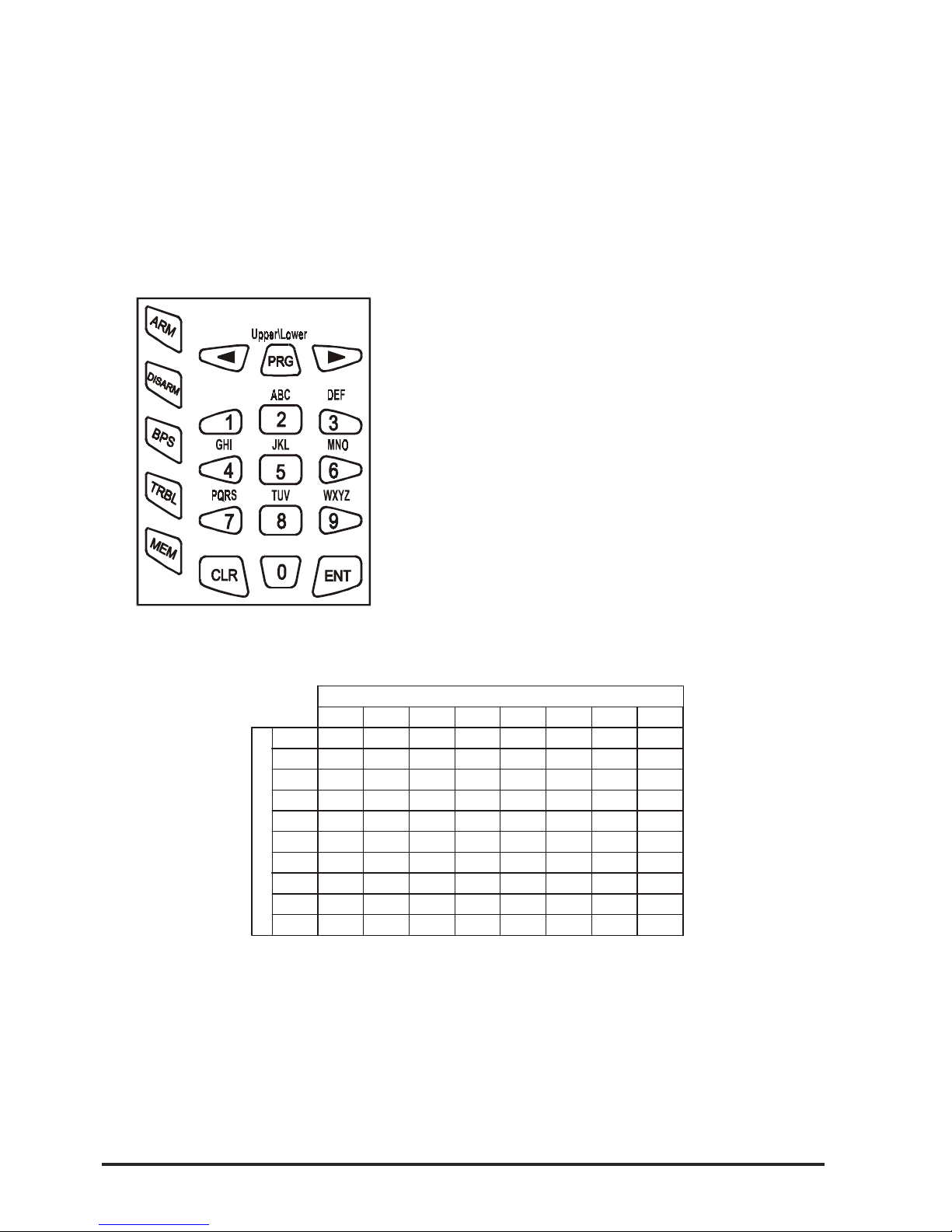
4. Fig. 1 shows LCD keys.
OTHER GUIDES
1. CA864 Alarm System Programming Manual – provides information on system programming.
2. CA864 Alarm System User Manual – provides information on user level system handling.
Table 1 Correspondence between number of key clicks and symbol
23
4
5
6781
0
1
2
3
4
5
6
7
8
9
0
.
,
:
!
<>
1
-
=
+
$%
@
/
2
3
4
5
6
7
8
9
ABCБВГ
Д
DEFЖЗИ
Й
GH I КЛМН
JKL
MNO
P
Q
RS
TUV
WX Y Z
ОПРС
ТУФХ
Ц
ЧШ
Щ
ЪЫЬ
ЭЮЯ
Keys
Number of clicks
Both figures and letters can be keyed in. The letters and
respective figure correspondence is shown in Fig. 1.
Any figure or letter can be introduced depending on the
number of clicks on the key. The PRG key changes capital to small case and vice-versa. Special symbols like
space or coma can be introduced by keying in the 1 and
0 keys. The correspondence between the number of key
clicks and the symbol to be displayed is shown in Table
1.
The arrows will shift the cursor within the edited section.
Pressing ENT confirms any changes. Pressing CLR rejects the changes.
Fig. 1 LCD keypad
Page 5

CA864 Installation manual 5
RESTORING FACTORY SETTINGS
Use the RESET jumper on the motherboard. Proceed as follows:
- Power down the system – both battery and mains;
- Place the RESET jumper on the main panel;
- Power up the system and remove the RESET jumper. System factory configurations have now been
restored. The Engineer Code is “7777”.
Partial restoration of system factory configurations is possible. The procedure has been described in
detail in Item 0.8.
STEPS FOR PROGRAMMING SYSTEM CONFIGURATIONS
In order to reduce the mistake and omission risk, it is advisable, after entering programming mode, to
follow the order of programming described below:
1. Install system-integrated modules – keyboard, zone expanders, programmable output expanders,
etc. Enter device input and output figures observing the requirements of your own security system. The
procedure has been described in Item 8.
2. Programme the areas within the system. The procedure has been described in Item 5.
3. Programme a code for each area or one code accessing all areas. The procedure is described in
Item 2.
4. Programme zones according to requirements – name the zones, programme the type and attributes
for the zones, determine system area attachment. The procedure is described in Item 3.
5. Programme outputs. The procedure is described in Item 4.
6. Programme system times (entry/exit, bell, date, time, etc.). Do not programme a Timeslot.
7. Programme other configurations.
8. Test the performance of the zones. The procedure is described in Item 0.
9. Leave programming mode and test the performance of the system according to requirements.
10. Go back to programming mode and adjust dialler. The procedure is described in Item 6.
11. Programme timeslots and test them carefully. The procedure is described in Item 1.
SETTING THE SYSTEM TO PROGRAMMING MODE
It is recommended to RESET in order to restore factory settings before attempting to programme the
new system.
To set the system to programming mode:
1. There must be no system-armed areas, as these will remain inaccessible for programming. To obtain
complete access to system configurations lift all protection from all areas. This does not apply to systems to be programmed for the first time after RESET.
2. There must be no areas in alarm mode. Such areas will remain inaccessible for programming until
the alarm mode is suspended.
3. Enter sysadmin access code. Default sysadmin access code is “0000”.
4. Press PRG to enter programming mode.
5. Press buttons “4” and “0” one after the other in order to enter Menu “Unlock Engineer Code”. Use the
arrows to position on “Single” (single access authorization) or “Always” (permanently authorized access).
6. Press 1 to allow engineer access to programming mode.
7. Press CLR until the TeleTek CA864 system message is displayed.
8. Enter Engineer Code. The default Engineer Code is “7777”.
9. You have now accessed programming mode.
Note: After the exit from the programming mode with “Single” access authorization of the engi-
neer, the system will block the engineer’s code. The procedure described in items 3 through 9
is to be performed in order to switch the system to programming mode.
Page 6

6 CA864 Installation manual
LEAVING PROGRAMMING MODE
To leave programming mode key in CLR until the display shows 9) Engineer out good-bye?, and then
confirm by pressing the ENT key.
The system must be checked for open zones before leaving programming mode. This is necessary
because any 24-hour open zone would sound the alarm upon leaving programming mode. If the sys-
tem siren is triggered, introduce a valid user code and then press the DISARM key to halt it.
To avoid this, go through the list of zones in menu 010, which are open or have a tampered self-protection circuit. Restore all zones, which may trigger off the alarm.
Physical and Logical Level of the System
The CA864-based security system should be considered as an entity operating at both the physical and
logical levels.
The physical level includes all modules and their resources (inputs and outputs). The restrictions at this
level relate to the number of modules that can be connected to the bus, i.e. up to 32. As to the resources
(inputs and outputs), there exist no restrictions at this level. This means that the modules actually connected to the bus can provide inputs and outputs in a larger number than those maintained at the logical
level.
The logical level of the system includes zones and their types, their belonging to groups and others, the
programmable outputs together with their operational logic; user codes with all their settings, established groups, etc. Generally, the logical level is the allocation of the resources available at the physical
level and the setting of the operation of the system as a security center.
Actually, zones and programmable outputs start operating only upon assignment of a logical number
and definition of the parameters of each one to be used. This is performed separately for each module
at the 8.0.x.x.0. Inputs config address for the inputs and 8.0.x.x.1. Outputs config for the outputs,
where x.x. denotes the shortcut address of the module. These addresses are inaccessible to modules
that have no resources at these addresses.
The restrictions for the zones are up to 64 logical numbers, while for programmable outputs they are up
to 48 logical numbers. Resources for modules that will not be used retain the logical number 00.
Procedure PnP for Identification of New Hardware
Each module of the set of the CA864 system has a unique number recorded in the manufacturing
process. It is with this number that the device will take part in the exchange on the bus. The number
consists of the serial number of the device plus a two-digit code corresponding to the module type.
The PnP procedure is used for switching on new modules connected to the bus in the logical structure
of the system. There exist two options for starting PnP:
- automatically upon power supply with Reset jumper installed. This option is used in the initial setting of
the network configuration. All modules need to have been connected in advance to the System Bus.
- manually from the 8.1. Add hardware address in the mode of programming by the engineer. This
option is used when the network is expanded with new modules or a defective module is replaced. The
new module needs to have been connected in advance to the System Bus.
When the PnP procedure is started, the main module of the system sends a command to identify new
devices to the modules on the bus. The procedure takes 20 seconds and ends up with the compilation
of a list of devices on the bus. This list can be seen at the 8.0 address in the mode of programming by
the engineer.
When a specific module is selected, the screen will display its unique number and the number of the
module on the list of devices on the bus (hereinafter referred to as “the shortcut address of the module”).
In the further programming at the logical level of the system, module resources will be identified with
regard to the module on the basis of its shortcut address.
Page 7

CA864 Installation manual 7
Replacement of a Defective Module
Modules need to be replaced in the system when a defect occurs. The in-built replacement procedure
can be used to avoid re-programming for the new module. Devices of the same type can be replaced.
As a result of this procedure, the whole programming of the defective device is transferred onto the new
one.
The sequence of operations is as follows:
1. Disable the defective module in the network temporarily. The command to disable it is given at the
8.0.x.x.3. Disable address, where x.x. is the shortcut address of the defective module.
2. Dismantle the defective module.
3. Install the new module at the same place.
4. Run the PnP procedure from the 8.1 Add hardware address.
5. After the procedure is over, the new module should have been added at the end of the list of modules.
6. A replacement command is given for the new module from the 8.0.x.x.6 Replace address, where x.x.
is the shortcut address of the new module. Here you have to enter the shortcut address of the defective
module.
Removal of a Module from the Network
If a module is to be removed from the system, the following sequence is applied:
1. Remove the module from the list of modules and the network, sending the command from the 8.0.x.x.5.
Remove address, where x.x. is the shortcut address of the module.
Temporary Disabling of a Module in the Network
The following sequence of operations is applied if a module is to be disabled temporarily in the network:
1. Disable the module temporarily in the network by sending a disabling command from the 8.0.x.x.3.
Disable address, where x.x. is the shortcut address of the module.
2. If necessary, the module can be enabled again and integrated into the normal operation of the system
with a command from the 8.0.x.x.4 Enable address, where x.x. is the shortcut address of the module.
Page 8
8 CA864 Installation manual
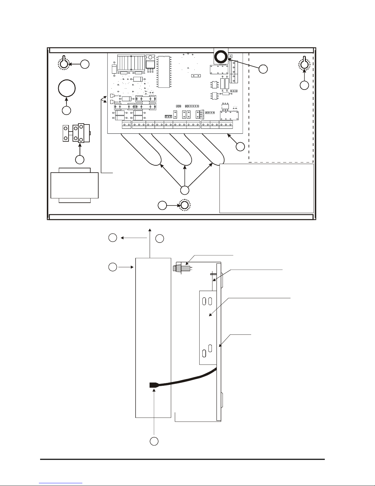
Fig. 2 CA864 control panel metal box
CA864 control panel metal box
TAMPER button
Front lid
Bottom
CA 864 control panel
Transmitter support strap
Pull lid forward 3
Lift lid up
2
Undo screws
1
4
Remove earthing cable
1
6
3
5
1
4
12V / 7 Ah
battery
F - 0,63 A
Mains
transformer
50 / 60 Hz
15-25 V / 50VA
1
Transmitter
MEMOCARD
MEMORY
RESET
LED
COMMUNICATOR
LED
AC
+BATT
-
F BATT
3A
F AUX
2A
F PGM
2A
BATT 3V
SERVICE
BUS CONNECTOR
B1 A1 ABBC
GROUND AC-- GND + AUX + OUT2 OUT3 OUT4 +PGM OUT5 I NP1 GND INP2 GNDINP3 INP 4 RED YELL GRN BLAC K
NO NC COMBUS CONNECTION
BLACKRED
TeleTek
CA 864
OUT1
2
1 - Support opening
2 - CA 864 control panel
3 - Mains power supplay terminal
4 - Signal cable openings
5 - Mains power supply cable
opening
6 - TAMPER button for box
self-protection
Page 9
CA864 Installation manual 9
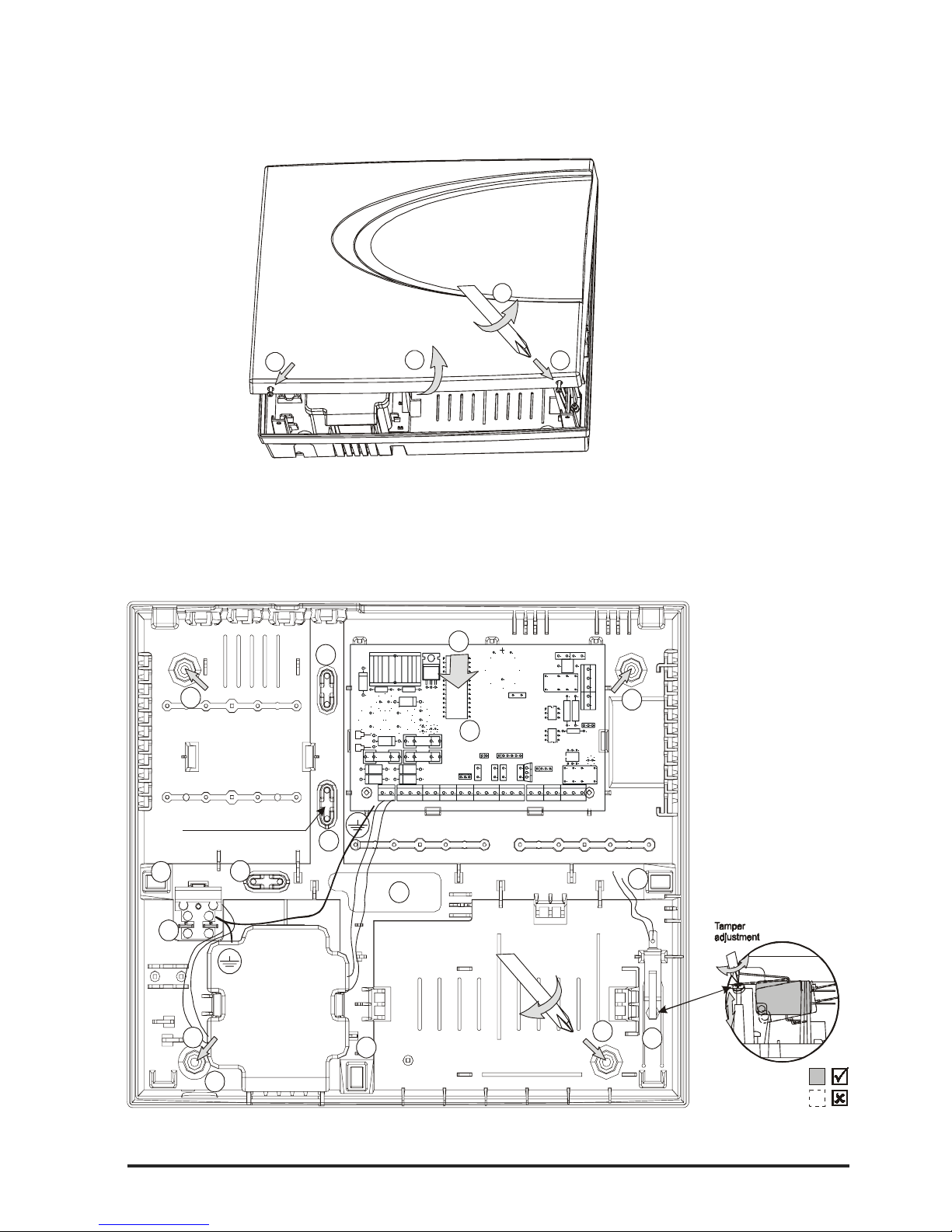
CA864 control panel plastic box
Fig. 2a CA864 control panel plastic box
2
1
1
1
Unscrew (1)
Remove cover (2)
7
8
6
6
6
6
6
6
5
4
3
2
2
2
2
A
c
c
u
m
u
l
a
t
o
r
c
a
b
l
e
1 - Central support
openin
g (
behind PCB
)
2 - S
3 - CA 864 control panel
4 - Mains power supply
terminal
5 - Main cable opening
7 -
8 - Tamper button for box
self-protection
upport opening
6 - Add. cable openings
Mains power supply
opening
Mains
transformer
50 / 60 Hz
15-25 V / 50VA
12V / 7 Ah
battery
Room for additional modules
Room for add. Modules
or transmitter
Use to fix
main power supply cable
F - 0,63 A
MEMOCARD
MEMORY
RESE T
LED
COMMUNICATOR
LED
AC
+
B
A
T
T
-
F BATT
3A
F AUX
2A
F PGM
2A
BATT 3V
SERVICE
BUS CONNECTOR
B
1
A
1
A
B
B
C
GROUND AC-- GND + AUX + OUT2 OUT3 OUT4 +PGM OUT5 INP1 GND INP2 GNDINP3 INP4 RED YELL GRN BLACK
NO NC COMBUS CONNECTION
B
L
A
C
K
R
E
D
CA 864
OUT1
1
Page 10
10 CA864 Installation manual
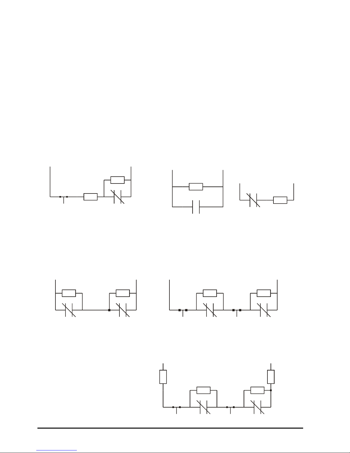
Idle device inputs (INPx) can be connected to the detectors as per the selected connection scheme.
The possible options for connecting the detectors to the inputs are given in Fig. 3. Attention must be paid
to programming the type of input connection in the system. The status of the Wire EOL and Doubling
configurations is indicated for every connection option.
!The Wire EOL and DOUBLING parameters have to be configured for all system inputs!
The necessary balance resistors have been placed in the spare parts pack accompanying the module.
!The sensors with contacts that by-pass the 1 k
ΩΩ
ΩΩ
Ω
resistors form first zone in double zoning, and
the sensors with contacts that by-pass the 2 k
ΩΩ
ΩΩ
Ω
resistors form second zone!
Fig. 3 Connecting sensors to CA864 system
inputs
Double style
NC NC
1K 2,2K
Zone input GND
Without EOL
(Wire EOL=OFF, DOUBLING=ON)
NCNC
TAMP E RTAMPER
1K 2,2K
GNDZone input
Without EOL, Open line recognition TAMPER
(Wire EOL=OFF, DOUBLING=ON)
TAMPER TAMPER
NC NC
GNDZone input
1K 2,2K
EOL
510
EOL
510
With EOL, Open line and Short on line
recognition (TAMPER)
(Wire EOL=ON, DOUBLING=ON)
Single style
TAMPER
NC
EOL
1K
1K
Zone input GND
With EOL, Open line and Short on line
recognition (TAMPER)
(Wire EOL=ON, DOUBLING=OFF)
Without EOL
(Wire EOL=OFF, DOUBLING=OFF)
NO
Zone input GND
Normally open
1K
NC
Zone input GND
Normally closed
1K
Page 11

CA864 Installation manual 11
When connecting outputs attention must be paid to the system output load-carrying capacities (PGM).
Figure 4 gives examples for connecting a relay to a light-emitting diode.
! When powering the system up after resetting factory configurations all system inputs are in
OFF status - +12 V voltage!
Fig. 4. Connecting relay and light-emitting diode to CA864 output
+ PGM
Output x
1 k
Ω
NC NO
COM
+ PGM
Output x
Page 12

12 CA864 Installation manual
CA864 control panel
The scheme of the CA864 control panel is provided in Fig. 5.
All CA864 system modules are connected via a quad system bus. The colours should correspond to the
colours marked on the terminal of the modules (see Fig. 5).
Fig. 5. CA864 control panel
MEMOCARD
MEMORY
RESET
LED
COMMUNICATOR
LED
AC
+BATT
-
F BATT
3A
F AUX
2A
F PGM
2A
BATT 3V
SERVIC E
BUS CONNECTOR
B1 A1 AB
BC
GROUND AC
--
GND + AUX + OUT2 OUT3 OUT4 +PGM OUT5 INP1 GND INP2 GNDINP3 INP4 RED YELL GRN BLACK
NO NC COM
FROM PUBLIC
TELEPHONE
NETWORK
TO PHONE
BUS CONNECTION
AC
15-25V
50 VA
AUXILIARY POWER
SUPPLY
2A TOTAL CONSUMPTION
PROGRAMMABLE
OUTPUTS
OPEN
COLLECTOR
Imax = 100mA
PGM, BELL POWER
POWER OU T
Imax 1А
RELAY OUTPUT
(DRY CONTACTS)
BUS DEVICE No1
BUS DEVICE No2
BUS DEVICE No31
BLACKRED
TeleTek
CA 864
RED
YELL
GRN
BLACK
RED
YELL
GRN
BLACK
RED
YELL
GRN
BLACK
OUT1
ZONES
Page 13

CA864 Installation manual 13
Power supply unit
The system power supply unit is located in the control panel box.
The auxiliary power supply voltage of the mains transformer should be within 15 – 25 V and of 50 VA.
!A 12 V and 7 Ah battery is connected to the CA864!
The supply to the module is connected to the system bus – RED and BLACK terminals.
Supply for control panel sensors is fed from +AUX+ and GND terminals.
Supply for auxiliary devices of the control panel (light indicators, relays, etc.) is fed from +PGM and GND
terminals.
!The RED and BLACK terminals on the system bus CANNOT BE USED to supply auxiliary devices (sensors, light indicators, relays, etc.) That supply can be controlled from the control panel
process block and can be interrupted!
An auxiliary power supply unit for the system is connected according to the scheme shown in Fig. 6.
CA864 control panel resources
There are four inputs at the control panel - INP1..INP4. These inputs are expanded to 8 for the double
zone.
There are five outputs at the control panel - OUT1..OUT5. The OUT1 output represents dry contacts of
a relay. Outputs OUT2, OUT3 and OUT4 are programmable outputs. Output OUT5 has a power supply
of up to 2 A to GND.
The CA864 control panel has an integrated digital dialler for transmitting messages to the central monitoring station via telephone line. The conductors from the telephone line socket are connected to terminals A and B. The telephone device is connected to terminals A1 and B1. No polarity has to be observed
when connecting the telephone line to the control panel.
Fig. 6. Connecting the auxiliary supply block to the CA864 system
Power supply unit
System bus
device
BLACK
GREEN
YELLOW
RED
BLACK
GREEN
YELLOW
RED
+
-
12V NO
System bus
device
Page 14

14 CA864 Installation manual
CA864 control panel terminals
MEMORY RESET – Producer default configurations can be restored by placing a bridging terminal and
feeding power supply to the control panel. This is recommended while installing the system and prior to
programming the parameters.
Producer default configurations can be restored at any time.
MEMOCARD - A MemoCard module is connected to this terminal. This module records the current
programming of the system or records some ready system configuration. The function can be used to
archivise system parameters.
SERVICE BUS CONNECTOR – A service LCD keypad is connected to this terminal. The keypad
allows for adjustments to be done to parameters of a system not connected to an LCD keypad.
A PC adaptor is also connected to this terminal. Thus the PC and the special Up/Down Load software
allow for adjustments to be done to system parameters.
CA864 control panel indications
Red LED AC – The light-emitting diode lights when there is mains supply and regular integrity of the
control panel power supply unit.
Green LED COMMUNICATOR - The light-emitting diode lights when the integrated digital dialler has
engaged the telephone line.
CA864 control panel fuses
F BATT fuss – A 3A battery fuss.
F AUX fuss – A 2A peripheral device power supply fuss. Output at + AUX.
F PGM fuss – A 2A power supply fuse for PGMx and +PGM outputs.
Technical specification ofCA864 control panel
Inputs - 4, can be expanded to 8
Outputs - 5
Quad system bus for connecting modules - Bus Connection
Mains transformer - 15-25 V, 50 VA
Battery charge - 13,8 V / 3 A
Battery - 12 V, 7 Ah
Consumption - nom 60 mA, max 100 mA
Sensor power supply (+AUX) - 13,8 V / 2 A
Auxiliary devices power supply (+PGM) - 13,8 V / 2 A
Auxiliary modules supply
(RED and BLACK terminals from System Bus) - 13,8 V / 2 A, self-restoring
Working temperature - (-20°C) to (+50°C)
Metal box dimensions - 320 x 265 x 80 mm
Page 15

CA864 Installation manual 15
CA864 LCD keypad module
The keypad front panel with liquid crystal display (LCD) is given in Fig. 7.
The back LCD keypad panel is given in Fig. 8.
A chart of the main LCD keypad plate is given in Fig. 9.
!Any single LCD keypad can service all areas within the system!
LCD keypad module resources
The LCD keypad module has one input marked as ZONE IN. There are two inputs for the double zone
keypad.
The LCD keypad module has one output marked as OUT. This is a programmable output.
The LCD keypad module houses a self-protection key. This is a double action key and has been configured
by the producer.
The BLACK, GREEN, YELLOW and RED terminals are used to connect the module to the system bus.
Power supply from the +AUX and +PGM control panel is used to feed the auxiliary devices (sensors,
relays, etc.).
!The RED and BLACK terminals of the system bus CANNOT BE USED to supply auxiliary devices (sensors, light indicators, relays, etc.). This supply can be controlled by the processing
block at the control panel and can be interrupted!
Fig. 7. Front panel of CA864 LCD keypad
TeleTek
LCD display
Indicators
Keys
Protective lid
Page 16

16 CA864 Installation manual
TAMPER
BUZZER
BLACK
GREEN
YELLOW
RED
ZONE IN
GND
OUT
Fig 8. CA864 LCD keypad
bottom
Fig. 9. CA864 LCD keypad
motherboard
Technical specifications of CA864 LCD keypad module
Inputs - 1, can be expanded to 2
Outputs - 1
Quad system bus for connecting to control panel
Consumption - nom 35 mA, max 60 mA
Auxiliary devices power supply (+AUX and +PGM from control panel) - 13,8 V / 2 A
Working temperature - (0°C) to (+50°C)
LCD keypad dimensions - 115 x 135 x 25 mm
Support openin
g
Support opening
Signal
cable
opening
Reciprocating
plate for
TAM PE R
button
Page 17

CA864 Installation manual 17
CA864 LED keypad module
The keypad front panel with light-emitting indication (LED) is given in Fig. 10.
The back LED keypad panel is given in Fig. 11.
A chart of the main LED keypad plate is given in Fig. 12.
!A LED keypad can service a maximum of two areas within the system!
!Where the keypad services one area the indication displays the first 16 zones in the area!
!Where the keypad services two areas the indication displays the first 8 zones in the area of the
first one (1 to 8 light-emitting diodes) and the first 8 zones in the area of the second one (9 to 16
light-emitting diodes)!
LED keypad module resources
The LED keypad module has no inputs or outputs
The LED keypad module houses a self-protection key. This is a double action key and has been configured
by the producer.
The BLACK, GREEN, YELLOW and RED platforms are used to connect the module to the system bus.
Fig. 10. CA864 LED keypad front panel
A
R
M
M
E
M
CL R EN T
0
12 3
4
56
789
P
R
O
G
D
I
S
A
R
M
System / area status
Zones 1 to 8 or first area zones
Zones 9 to 16 or seccond area zones
Protective lid
Keys
Page 18

18 CA864 Installation manual
Fig. 11. CA864 LED keypad bottom
Fig. 12. CA864 LED keypad motherboard
Technical specifications of CA864 LED keypad module
Inputs - none
Outputs - none
Quad system bus for connecting to control panel
Consumption - nom 15 mA, max 60 mA
Auxiliary devices power supply (+AUX and +PGM from control panel) - 13,8 V / 2 A
Working temperature - (0°C) to (+50°C)
LED kypad dimensions - 75 x 85 x 18 mm
Support openings
Support openings
Signal
cable
opening
Reciprocating
plate for
TAM PE R
button
TAMPER
Page 19

CA864 Installation manual 19
CA864 input (ZONE) expander module MRI4/8
A zone expander image has been provided in Fig. 13.
CA864 input expander module MRI4/8 resources
The zone expander module has four inputs marked as INPUT1…INPUT4. There are eight inputs for the
double zone expander.
The zone expander module has two outputs marked as OUT1 and OUT2. These are programmable
outputs.
The BLACK, GREEN, YELLOW and RED terminals are used to connect the module to the system bus.
Power supply from the +AUX and +PGM control panel is used to supply auxiliary devices (sensors,
relays, etc.).
!The RED and BLACK terminals of the system bus CANNOT BE USED to supply auxiliary devices (sensors, light indicators, relays, etc.). This supply can be controlled by the processing
block at the control panel and can be interrupted!
Technical specifications of CA864 input expander module MRI4/8
Inputs - 4, can be expanded to 8
Outputs - 2
Quad system bus for connecting to control panel – Bus Connection
Consumption - nom 15 mA, max 20 mA
Auxiliary devices power supply (+AUX and +PGM from control panel) - 13,8 V / 2 A
Working temperature - (0°C) to (+50°C)
Inputs module dimensions - 92 x 43 mm
Fig. 13 CA864 input expander MRI4/8
TAMPER LOOP
SERVICE LED
Page 20

20 CA864 Installation manual
CA864 output expander module (PGM) MRO8
An output expander module image is given in Fig. 14.
Output expander module MRO8 resources
The output expander module has no inputs.
The output expander module has eight inputs marked as OUT1…OUT8. These are programmable
outputs.
The BLACK, GREEN, YELLOW and RED terminals are used to connect the module to the system bus.
Power supply from the +AUX and +PGM control panel is used to supply auxiliary devices (sensors,
relays, etc.).
!The RED and BLACK terminals of the system bus CANNOT BE USED to supply auxiliary devices (sensors, light indicators, relays, etc.). This supply can be controlled by the processing
block at the control panel and can be interrupted!
Technical specifications of CA864 output expander module MRO8
Inputs - none
Outputs - 8
Quad system bus for connecting to control panel – Bus Connection
Consumption - nom 15 mA, max 100 mA
Auxiliary devices power supply (+AUX and +PGM from control panel) - 13,8 V / 2 A
Working temperature - (0°C) to (+50°C)
PGM expander module dimensions - 92 x 43 mm
Fig. 14 PGM output expander MRO8
TAMPER LOOP
SERVICE LED
Page 21

CA864 Installation manual 21
IInstallation box for input and output expander modules
The terminals are installed in the box (fig. 15) by the producer. A maximum of two input and/or output
expanders can be installed in one box, as shown in Fig. 15.
The self-protection key is installed and configured by the producer.
Technical specifications of the expander installation box
Box dimensions - 128 x 103 x 54 mm
terminal
terminal
TAMPER button for box self-protection
Expander board
(inputs or outputs
Expander board
(inputs or outputs)
Lid support
openings
Wall support openings
Wall support openings
Fig. 15 Installation box for Input and Output expander modules
Page 22

22 CA864 Installation manual
Installation for input and output expander modules in plastic box
The producer has provided additional positions for extra modules and devices for the plastic box (fig.
15a). Up to four expanders for inputs and/or outputs can be fitted together with control panel and
accumulator, as it is shown on fig. 15a.
Fig. 15a Installation for Input and Output expander modules
Room for second
expander module
Expander module
Page 23

CA864 Installation manual 23
CA 864 DIO32 module (Dynamic indication)
A layout of the DIO dynamic indication module is given in Fig. 16.
Use of CA864 DIO32 module
The DIO module is designed to make dynamic indication mnemo-panels. Visualisation of the system
area status (ALARM / MEMORY, NORMAL, ARM and DISARM) or of the system zone status (TAMPER/
FIRE, ALARM / MEMORY, OPEN or CLOSE) is possible. The zones have been divided into two areas –
from 1 to 32 and from 33 to 64.
CA864 DIO32 module resources
The DIO module has one programmable output marked PGM. This is a potential output. The programmable PGM output has been duplicated by a “dry” contact relay. The relay contacts are labelled COM,
NO and NC.
The BLACK, GREEN, YELLOW and RED terminals are used to connect the module to the system bus.
Auxiliary devices (sensors, sound indicators, etc.) are powered by the +AUX and +PGM control panel or
by the +12V power supply tapped at the +PGM clamp.
!Attention must be paid that the RED (+12V) clamp system bus supply is tapped to the + PGM
clamp. This supply can be controlled by the processing block at the control panel and can be
interrupted!
Two ….. type couplings have been placed on the board. These couplings are designed to connect the
light-emitting diodes at the mnemo-panel. The Anode/Cathode correspondence has to be observed
when connecting these light-emitting diodes – Fig. 16 – Anode row and Cathode row.
!Connect light-emitting diodes only to the light-emitting diode indication outputs!
Fig. 16 CA864 DIO dynamic indication module
BUZZER
LED
JP1
JP2
JP3
BUZZER
AREAS / ZONES
1 - 32 / 33 - 64
DIO - 32
ver. 2.0
LED LIGHT CON TROL
-
+
1
2345678
9
10111213141516
33343536373839
404142434445464748
49
505152535455565758596061626364
RED
YELLOW
GREEN
BLACK
+PGM
PGM
NO
NC
COM
TEST
ANODE
CATHODE
ANODE
CATHODE
LED brightness
adjustment
Sound signal for
integrated
programmable
output
(JP1 - CLOSED)
Office
indication
Support openings
Support openings
1
2
3
456
789
101112
13
14
15
16
171819
202122
23
24
25
26272829303132
1
2345678
9
10111213141516
AREAS (ARMED or DISARMED)
(JP2 - OPEN)
AREAS (ALARM/MEMORY or NORMAL STATE)
(JP2 - OPEN)
ZONES (JP2 - CLOSED; JP3 - OPEN for 1 - 32 ZONE or JP3 - CLOSED for 33 - 64 ZONE)
Page 24

24 CA864 Installation manual
Adjusting the CA864 DIO32 module
To adjust the DIO module use JP1, JP2 and JP3 jumper connectors:
- JP1:
Where the JP1 jumper connector has been placed, the board-located zoom repeats the PGM output
status – the PGM zoom emits a continuous sound signal if PGM output is active.
Where the JP1 jumper connector has been removed, the board-located zoom is switched off. This does
not interfere with PGM output performance.
- JP2:
Where the JP2 jumper connector has been placed, the LED indication outputs will visualize the system
zone status. Depending on the configuration adjustments with JP3 jumper connector, the status of 1 to
32 or 33 to 64 zones will be displayed.
Where the JP2 jumper connector has been removed, the LED indication outputs will visualize the system area status as follows:
—> the left-hand side coupling light-emitting diodes (1 to 16):
constant light – the area is in ALARM or MEMORY state
no light – the area is in regular NORMAL state
—> the right-hand side coupling light-emitting diodes (17 to 32):
constant light – the area is armed
no light – the area is disarmed
- JP3:
Where the JP3 jumper connector has been placed, the LED indication outputs will visualize the status of
zones 33 to 64 zone. The JP2 jumper connecter has to be placed.
Where the JP3 jumper connector has been removed, LED indication outputs will visualize the 1 to 16
zone status. The JP2 jumper connector has to be placed.
Zone information data is as follows:
LED blinks – the zone is in TAMPER or FIRE state
constant LED light – the zone is in ALARM or MEMORY state. Where the zone is in neither of the
specified states, this indication means an open/closed zone
no LED light – the zone is in normal state.
LED brightness can be regulated with the help of the LED LIGHT CONTROL potentiometer.
A normal open contact button can be connected to the TEST clamps. Regular check-ups of mnemopanel integrity can be performed.
Pressing and holding the TEST button until all LEDs light up permanently can initiate the mnemo-panel
integrity test. LED1 only will be displayed after the button is released (see Fig. 16). A single click will take
you over to the following LED – 2, 3, 4 … 32. The next TEST button click will resume mnemo-panel
operation mode.
!Mnemo-panel operation mode will automatically resume if the TEST button is not pressed within
30 seconds!
Technical specifications of CA864 DIO32 module
Inputs - none
Outputs - 1 potential, duplicated with relay; sound indication option together with output status indication
LED outputs - 32
Quad system bus for connecting to control panel - Bus Connection
Consumption - max 200 mA (LED’s connected)
Auxiliary devices power supply (+AUX and +PGM from control panel) - 13,8 V / 2 A
Working temperature - (0°C) to (+50°C)
DIO module dimensions - 125 x 85 mm
Support openings dimensions - 114 x 67 mm
Page 25

CA864 Installation manual 25
TAMPER
COM
NO
RED
GREEN
YELLOW
BLACK
Фиг. 17 Proxi Reader CA864
Proxi Reader Module CA864
The Proxi Reader module is given in Fig. 17.
Resources of Proxi Reader Module CA864
Proxi Reader Module has an in-built relay with unplugged contacts. The contacts of the relay are designated by COM and NO.
Proxi Reader Module as an in-built sound indicator to send sound signals when operating the module.
Proxi Reader Module has an in-built three-colour LED indication light diode to send light signals when
operating the module.
The BLACK, GREEN, YELLOW и RED clamps are to connect the Module to the System Bus.
The plugs in the control panel +AUX and +PGM are used for any additional devices (relays, sound
indicators, etc.).
Purpose of Proxi Reader Module CA864
The purpose of Proxi Reader Module is to operate proxy-cards in the system.
A module can operate all the cards in the system. Besides, the module has an in-built relay. It is used to
set the electronic lock of the door.
Technical specifications of Proxi Reader CA864 module
Inputs - none
Number of outputs – one relay with normally open contact to plug the power supply to the electronic lock.
Quad system bus for connecting to control panel - Bus Connection
Consumption - max 170 mA
Working temperature - (0°C) to (+50°C)
Page 26

26 CA864 Installation manual
CA864 printer module APR
CENTRONICS interface. Can operate only with DOS-compatible printers.
The CENTRONICS36 type terminal is used to connect to the printer. The other end of the module
observes the colour correspondence to connect to the System Bus.
Indication of the status of the printer and of the work mode control can be done through the engineer
programming mode.
The procedures for working the printer module are given in the CA864 Alarm System Programming
Manual.
CA864 PC adapter module APC
RS-232 interface. Needs PC with serial port RS-232 and installed software for Up/Down Load remote
programming.
A Cannon25 type terminal is connected to the COM serial port of the PC. The other end of the module is
connected to the SERVICE BUS CONNECTOR terminal at the control panel by observing the colour
correspondence.
Cable length must not exceed 2 m.
The procedures for working the Up/Down Load programme are given in the CA864 Alarm System
Remote Programming Manual.
!Please, check the PC you are going to use for existing serial port RS-232 with Cannon25 type
terminal. If such is not presented you may need a Cannon 25 to Cannon 9 converter!
CA864 MEMOCARD module
The MemoCard Module is used to store the programmed configuration of the CA864 system.
The direction of the connection must be observed when connecting the module to the MEMOCARD
terminal.
The procedures for working the MemoCard module are given in the CA864 Alarm System Programming
Manual.
Technical specifications of CA864 printer module APR
Quad system bus for connecting to control panel – Bus Connection
Consumption - nom 80 mA
Working temperature - (0°C) to (+50°C)
Technical specifications of CA864 PC adapter module APC
Cable length - 2 m.
Exchange rate - 9600 bps
Quad system bus for connecting to control panel – Bus Connection
Consumption - nom 10 mA
Working temperature - (0°C) to (+50°C)
Page 27

CA864 Installation manual 27
SUPPLEMENT A - Menu structure chart for programming the CA864 alarm system
The programming chart allows for a quick scan of all menus for configuration programming of the CA864
Alarm System.
There are two ways to access a specific programming menu.
1. Use the Down Arrow, Up Arrow, ENT or CLR keys to browse the menu. These keys are showed in the
chart.
The symbols, which represent the keys, are as follows:
2. Use the short menu code. Simply introduce the digits displayed on the chart in the respective menu
and the system will be immediately positioned onto the menu you requested. This is a quicker method
than the previous one as it only requires several clicks on some of the keys. At the same time it guards
you from misclicks.
The quick menu access code is not displayed on the keypad. It is on the chart.
ENT. Pressing ENT accesses the succeeding level of menu structure.
Pressing CLR accesses the preceding level of menu structure.
Right arrow key. Pressing the right arrow key accesses the succeeding menu of a
given level within the structure of menus.
Pressing the left arrow key accesses the preceding menu of a given level with the
structure of menus.
ENT
Page 28

28 CA864 Installation manual
0) Maintenance 0) Display Log 0) All Areas
1) Select Area0) All Areas
1) Select Area
1) Show Open Z-s
2) Zone Walk Test
3) PGM Test
4) Printer Test
5) Dialer Test
6) System Troubles
7) LCD Settings 0) Contrast
1) Backlight
8) Reset Menu
2) Private Display
3) Edit Logo
2) Zones
3) PGMs
4) Areas
5) Proximity Cards
0) Device Inputs
1) Device Outputs
0) AC-trbl delay
1) Show Troubles
1) Time Slots
Five TimeSlots:
3) Def. XHolidays
4) Def. XXHolidays
2) Users 0) User Codes
1) Code Length
2) ChangeEng.Code
C.01 - Code Name
. . .
C.96 - Code Name
0) Rename Code
1) User Ri ghts 0) Areas: 12345678
1) Areas 9-162) User Attributes
0) Add Card
To Zones
0) Def. Timeslots
1) Def. XTimeslots
2) Def. Holidays
ENT ENT
ENT
ENT
ENT
ENT
ENT
ENT
ENT
ENT
ENT
ENT
ENT
1) Phone 1 Test
2) Phone 2 Test
3) Phone 3 Test
4) Phone 4 Test
ENT
0) Time Slots
1) Users
6) Devices
0) Start/Stop Time
1) Week Days
2) Holyday slotHoliday N 01 .. 30
ENT
ENT
TimeSlot N 01 .. 20
ENT
XTimeSlot N 21 .. 25
ENT
dd:mm dd:mm
ENT
ENT
XXHoliday N 40 .. 45 Four XHolidays:
ENT
ENT
XHoliday N 31 .. 40 Four Holidays:
ENT
3) User Timeslot
4) User Proxi Card
2) Entry Rights
3) Remove Card
1) Arm/D Rights
ENT
Page 29

CA864 Installation manual 29
3) Zones 0) Definition
01 Zone Name
. . .
64 Zone Name
0) Areas 12345678
1) Areas 9-163) Zone parameters
4) Zone Timeslot
5) Entry/Stay Delay
1) Auto Shutdown
2) Double Knock
3) Zones Hardware
Instant
Entry delay
Follow
24h Burglary
Delayed 24h Fire
Standart 24h Fire
Stay delay
Key-switch
Power monitor
Panic
Tamper
Medical
24h non burgl ary
Zone Type:
Key Parameters:
ArmOnly/ArmDis
Stay Arming
Force Arming
Instant Arming
Zone Parameters:
Auto Shutdown
Bypass Enabled
Stay Zone
Force Zone
Double Knock
Chime
Steady Alarm
Pulsed Alarm
Silent Alarm
Report Only
4) Outputs 0) PGM Definition
01
. . .
F( ). N: 16
0) Activation by
1) Deactivation by 0) Event
1) Time period2) Normal State
F( ). N: 01
0) Switch A (_/_) PGM 00 . . 48:
1) Switch B (_/_)
PGM 00 . . 48:2) Switch C (_/_)
3) Switch D (_/_) PGM 00 . . 48:
PGM 00 . . 48:
Activation and Deactivation Events:
Fixed time N
Sys Trbl. N
SysSt atus N
Silnt Alrm A
AudblAlrm A
Fire Alrm A
FireDelay A
Tamper A
Disarming A
Bypass in A
Auto Arm A
Panic A
Arming A
Ready A
User code N
ArmingCode N
DisarmCode N
OK Zone N
Open Zone N
Bypass Zon e N
Fault Zone N
Alarm from Z
Rest.Zone N
Access KBD
Function N
Siren for A
FireReset A
A- N- Z- KBD-
Area Code or Function number Zone Keypad
0) Rename Zone
1) Zone Type
2) Attach to Area
. . .
48
1) Function Def.
Function Descript ion
A
B
CD
ENT ENT
ENT
ENT ENT ENT
ENT
ENT
ENT ENT
ENT
ENT
ENT
ENT
3) Bell Options
4) Bell Cut-off time
5) Assig n Timeslot
6) Exit Time
7) Disarm Options
1) Area assign Device 01 . . 32 0) Assign to A 1-8
1) Assign to A 9-16
5) Split System 0) Define Areas
01 Area Name
. . .
16 Area Name
0) Rename
1) Options
2) Panic Options
ENT ENT
ENT ENT
ENT
To Dialer Menu
Page 30

30 CA864 Installation manual
6) Dialer 0) Tel. Numbers 1) Ctrl. Station 1
2) Ctrl. Station 2
3) Ctrl. Station 3
4) Ctrl. Station 4
1) Account Number
01 Area
. . .
16 Area
2) Wait Dial Tone
3) Report Options 0) Areas rep. opt. 0) Arm/disarm
01 Area rep. codes
1) PC ID number
6) Up/down load
4) Call Back
5) Answer machine
0..9-phone digits
P-puls dialing
T-tone dialing
D-dela y 4 se conds
W-wait dial tone
Telephone number
symbols:
. . .
16 Area rep. codes
1) Alarm/Restore
2) Tamper/Restore
1) System rep. code 0) Trouble/Restore
1) Special Report
2) Medical Report
3) Fire Report
4) Test Call Time
5) Line Monitor 0) TL Monitoring
1) TLM Trbl Delay
0) PC phone N:
3) Number of rings
2) Panel ID number
ENT
ENT
ENT
ENT ENT ENT
ENT
ENT
ENT
7) Peripherals 0) Printer
1) Memory Card 0) Upload to Card
1) Downl. from Card
Commands for printer control
no printing
test printer
Devices
Zones
Areas
User Codes
Timeslots
PGM
Functions
System
UpDownLoad
LogFile
online prin ting
8) System edit 0) Device config
01 device
. . .
32 device
0) Inputs config
1) Outputs config
2) Assign Trouble
3) Disable
4) Enable
5) Remove
6) Replace device
1) Add hardware
9) Engineer out
ENT ENT
ENT
ENT
ENT
2) Info
Page 31

CA864 Installation manual 31
SUPPLEMENT B – Chart for user programmable menus
Arming 3) Full arming
4) Stay arming
5) Force arming
6) Instant arming
7 ARM all area)
Disarming
Programming 1) Own code 0) Rename
1) Change code
2) User codes 0) Rename code
1) Change code
2) User rights
0) Add Card
2) Entry Rights
3) User Attributes
5) User Proxi Card
3) Time set
5) Chime
6) LCD settings
2) Private Display
3) Edit Logo
Memory (Log file) 0) All Areas
1) Select Area
TRBL (troubles)
BPS (Bypass zone)
01 Area name
. . .
16 Area name
01 Area name
. . .
16 Area name
01 Area name
. . .
16 Area name
C.01 - Code Name
. . .
C.96 - Code Name
01 Area name
. . .
16 Area name
. . .
16 Area name
01 Area name
. . .
16 Area name
01 Area name
0) UnlockEngineer
1) UDL user codes
4) Engineer rights
4) User Time Slot
0) Areas: 12 345678
1) Areas: 9
10 12 14 16
11 13 15
3) Remove Card
1) Arm/D Rights
0) Contrast
1) Back light
Page 32

32 CA864 Installation manual
Guarantee
During the guarantee period the manufacturer shall, at its sole discretion, replace or repair any
defective product when it is returned to the factory. All parts replaced and/or repaired shall be covered
for the remainder of the original guarantee, or for ninety (90) days, whichever period is longer. The
original purchaser shall immediately send manufacturer a written notice of the defective parts or
workmanship, which written notice must in all cases be received prior to expiry of the guarantee.
International Guarantee
Foreign customers shall enjoy the same guarantee rights as those enjoyed by any customer in Bulgaria,
except that manufacturer shall not be liable for any related customs duties, taxes or VAT, which may be
payable.
Guarantee Procedure
This guarantee will be granted when the appliance in question is returned. The manufacturer shall
accept no product whatsoever, of which no prior notice has been received.
Conditions for waiving the guarantee
This guarantee shall apply to defects in products resulting only from improper materials or
workmanship, related to its normal use. It shall not cover:
§ Damages resulting from transportation and handling;
§ Damages caused by natural calamities, such as fire, floods, storms, earthquakes or lightning;
§ Damages caused by incorrect voltage, accidental breakage or water; beyond the control of
the manufacturer;
§ Damages caused by unauthorized system incorporation, changes, modifications or
surrounding objects:
§ Damages caused by peripheral appliances (unless such peripheral appliances have been
supplied by the manufacturer:
§ Defects caused by inappropriate surrounding of installed products;
§ Damages caused by failure to use the product for its normal purpose; Damages caused by
improper maintenance;
§ Damages resulting from any other cause, bad maintenance or product misuse.
In the case of a reasonable number of unsuccessful attempts to repair the product, covered by this
guarantee, the manufacturer’s liability shall be limited to the replacement of the product as the sole
compensation for breach of the guarantee. Under no circumstances shall the manufacturer be liable
for any special, accidental or consequential damages, on the grounds of breach of guarantee, breach
of agreement, negligence, or any other legal notion.
Waiver
This Guarantee shall contain the entire guarantee and shall be prevailing over any and all other
guarantees, explicit or implicit (including any implicit guarantees on behalf of the dealer, or adaptability
to specific purposes), and over any other responsibilities or liabilities on behalf of the manufacturer.
The manufacturer does neither agree, nor empower, any person, acting on his own behalf, to modify
or alter this Guarantee, nor to replace it with another guarantee, or another liability with regard to this
product.
Unwarranted Services
The manufacturer shall repair or replace unwarranted products, which have been returned to its
factory, at its sole discretion under the conditions below. The manufacturer shall accept no products
for which no prior notice has been received.
The products, which the manufacturer deems repairable, will be repaired and returned. The
manufacturer has prepared a price list and those products, which can be repaired, shall be paid for
every repaired appliance.
The closest equivalent product, available at the time, shall replace the products manufacturer deems
unrepairable. The current market price shall be charged for every replaced product.
No: 18020317, Rev. A 07\05
 Loading...