

Page 1

Alarm Control Panel
CA62
Installation and Programming
Manual
WARNING
This manual contains information on limitations regarding product use and function and information
on the limitations as to liability of the manufacturer. The entire manual should be carefully read.
The information in this manual is a subject to change without notice!
C
Page 2

Guarantee
During the guarantee period the manufacturer shall, at its sole discretion, replace or repair any defective product when it is returned
to the factory. All parts replaced and/or repaired shall be covered for the remainder of the original guarantee, or for ninety (90) days,
whichever period is longer. The original purchaser shall immediately send manufacturer a written notice of the defective parts or
workmanship, which written notice must in all cases be received prior to expiry of the guarantee.
International Guarantee
Foreign customers shall enjoy the same guarantee rights as those enjoyed by any customer in Bulgaria, except that manufacturer
shall not be liable for any related customs duties, taxes or VAT, which may be payable.
Guarantee Procedure
This guarantee will be granted when the appliance in question is returned. The manufacturer shall accept no product whatsoever, of
which no prior notice has been received.
Conditions for waiving the guarantee
This guarantee shall apply to defects in products resulting only from improper materials or workmanship, related to its normal use. It
shall not cover:
• Damages resulting from transportation and handling;
• Damages caused by natural calamities, such as re, oods, storms, earthquakes or lightning;
• Damages caused by incorrect voltage, accidental breakage or water; beyond the control of the manufacturer;
• Damages caused by unauthorized system incorporation, changes, modications or surrounding objects:
• Damages caused by peripheral appliances (unless such peripheral appliances have been supplied by the manufacturer:
• Defects caused by inappropriate surrounding of installed products;
• Damages caused by failure to use the product for its normal purpose; Damages caused by improper maintenance;
• Damages resulting from any other cause, bad maintenance or product misuse.
In the case of a reasonable number of unsuccessful attempts to repair the product, covered by this guarantee, the manufacturer’s liability shall be limited to the replacement of the product as the sole compensation for breach of the guarantee. Under no circumstances
shall the manufacturer be liable for any special, accidental or consequential damages, on the grounds of breach of guarantee, breach
of agreement, negligence, or any other legal notion.
Waiver
This Guarantee shall contain the entire guarantee and shall be prevailing over any and all other guarantees, explicit or implicit (includ-
ing any implicit guarantees on behalf of the dealer, or adaptability to specic purposes), and over any other responsibilities or liabilities
on behalf of the manufacturer. The manufacturer does neither agree, nor empower, any person, acting on his own behalf, to modify
or alter this Guarantee, nor to replace it with another guarantee, or another liability with regard to this product.
Unwarranted Services
The manufacturer shall repair or replace unwarranted products, which have been returned to its factory, at its sole discretion under
the conditions below. The manufacturer shall accept no products for which no prior notice has been received.
The products, which the manufacturer deems repairable, will be repaired and returned. The manufacturer has prepared a price list
and those products, which can be repaired, shall be paid for every repaired appliance.
The closest equivalent product, available at the time, shall replace the products manufacturer deems unrepairable. The current market price shall be charged for every replaced product.
Page 3

Installation and Programming Manual - СА62 Alarm Control Panel 3
CONTENTS
SECTION 1: INSTALLATION
1. Introduction ............................................................................................................................................................ 4
2. Installation.............................................................................................................................................................. 5
2.1 General Information ................................................................................................................................. 5
2.2 CA62 Installation Steps ............................................................................................................................5
2.3 СА62 Alarm Control Panel Metal Box ...................................................................................................... 6
2.4 CA62 Alarm Control Panel Plastic Box .................................................................................................... 7
2.5 CA62 Alarm Control Panel Inputs and Outputs ........................................................................................ 8
2.6 Connecting of Detectors to CA62 Alarm Control Panel ............................................................................ 9
2.7 Connecting of Peripheral Devices to СА62 Alarm Control Panel ............................................................. 11
2.7.1 Connecting LED and LCD Keyboards to CA62 Alarm Control Panel ........................................ 11
2.7.2 Connecting of Proxi Reader PR62 to CA62 Alarm Control Panel .............................................. 13
2.8 Using of PGM1, PGM2 and PGM3 Programmable Outputs .................................................................... 14
2.9 Using of SIREN Programmable Output .................................................................................................... 14
2.10 Connecting the CA62 Built-in Digital Communicator .............................................................................. 15
2.11 Installing of VD60 voice dialer to CA62 Alarm Control Panel ................................................................. 15
2.12 Installing of AJAX LAN Module in CA62 Alarm Control Panel ............................................................... 16
2.13 Connecting of UWE432 Universal Wireless Expander to CA62 Alarm Control Panel ........................... 16
2.14 Powering up the CA62 Alarm Control Panel .......................................................................................... 17
2.14.1 Technical Trouble Indication ..................................................................................................... 17
SECTION 2: Programming
1. Programming the Software Parameters of СА62 Alarm Control Panel ............................................................ 18
2. The symbols used in this manual ........................................................................................................................ 18
3. Programming of CA62 via LED or LCD Keyboard .............................................................................................. 18
4. Remote Programming of CA62 ............................................................................................................................19
5. Programming of Default Congurations in the CA62 Alarm Control Panel ..................................................... 19
Menus for Programming the Software Parameters of CA62:
0. Engineer Parameters and Common Settings ............................................................................................. 20
1. User and Manager Codes Programming ................................................................................................... 26
2. Programming of Zones ............................................................................................................................... 28
3. PGM and SIREN Outputs Programming .................................................................................................... 35
4. PARTITIONS Programming .......................................................................................................................40
6. Programming of Communication Devices .................................................................................................. 42
6.1 General parameters .......................................................................................................................... 42
6.2 Remote programming ....................................................................................................................... 46
7. Programming of Peripheral Devices .......................................................................................................... 47
7.1 Programming of Keyboards .............................................................................................................. 47
7.2 Programming of Proxi Readers ......................................................................................................... 49
SUPPLEMENTS
SUPPLEMENT А - Default Programming Tables (after RESET procedure):
TABLE 1 - Engineer Programming ................................................................................................................. 50
TABLE 2 - Manager Programming ................................................................................................................. 58
TABLE 3 - User Programming ........................................................................................................................ 61
SUPPLEMENT B - Examples for Security Application with CA62 ........................................................................62
SUPPLEMENT C - Additional Information:
Coding recordings in log events ..................................................................................................................... 65
Table of protocol Contact ID transmitted codes from CA62 ........................................................................... 67
Table of protocol SIA transmitted codes from CA62 ...................................................................................... 68
Hexadecimal table .......................................................................................................................................... 69
SUPPLEMENT D - Algorithms for Operation of ZONES with Key-Switch Type .......................................................... 70
SUPPLEMENT E - Algorithm for Recording and Listening of Voice Messages .......................................................... 72
SUPPLEMENT F - General Connection Diagram ....................................................................................................... 74
Solving of Technical Problems During Powering up of CA62 ............................................................................... 75
Page 4

4 Installation and Programming Manual - СА62 Alarm Control Panel
SECTION 1: INSTALLATION
1. Introduction
The СА62 alarm control system is an upgraded version of СА60plus and is designed for security and protection of residential and ofce buildings. The system is based on a modular principle.
The programming of CA62 can be done by two types of keyboards (LED or LCD) or remotely via ProsTE software.
The security control is managed by means of a keyboard or a proxi reader.
General specications of СА62 alarm control panel:
Inputs: • 6 inputs for connecting detectors (5 inputs on the panel and 1 in the keyboard).
Zones: • From 6 to 12 zones with freely programmable parameters.
• Doubling the zone number in the panel by means of specic connection of the detectors.
• Individually settings for the balancing type of each input - one or two balancing resistors or zone doubling.
Partitions: • Two fully independent partitions in the system.
• Arming modes:
- Full (Arming of all zones in the system);
- Instant (Partial arming - the user is allowed to stay in some zones; the entry zone is secured and any intru-
sion will starts the alarm immediately;
- Stay (Partial arming - the user is allowed to stay in some zone; the entry zone is secured, an entry time
will start up in case of an intrusion).
• Security control by means of Proximity cards reader PR62.
• Auto Arming mode for arming the security areas in preprogrammed time.
Outputs: • 3 weak current and 1 power current programmable outputs type ОС (open collector).
• Same options for programming of all outputs.
Codes: • 4 or 6 digits access codes.
• 20 User codes, 4 Manager codes, 1 Engineer code.
• Programmable function “Ambush code” - generates a "silent" panic alarm, when the user is forced to
disarm the system.
• Supervised access of the Engineer to the programmed parameters in the system.
Events LOG:
Report to a
Monitoring
Station:
Peripheral
Devices:
Programming: • The alarm panel parameters can be programmed from every keyboard (LED or LCD) in the system.
Technical
Specications:
• Memory LOG for 256 events with time and date - can be viewed by a keyboard or via
• Built-in digital communicator for central station monitoring via telephone line. “Contact ID” and “SIA” stand-
ard protocols are supported.
• AJAX - LAN (TCP/IP) communication module.
• VD60 - Voice dialer.
• Up to 4 keyboards - LED and/or LCD models.
• Up to 2 proximity cards readers - PR62.
• Supported keyboards for CA62:
- LED61 - Keyboard with LED display up to 6 zones.
- LED62 - Keyboard with LED display up to 12 zones, supports operation with 2 Partitions (A and B).
- LED63 VG SE - Keyboard with LED display up to 12 zones, supports operation with 2 Partitions (A and B).
- LCD62 - Keyboard with icon LCD display up to 6 zones.
- LCD62В - Keyboard with icon LCD display up to 6 zones (blue backlight of the display).
- LCD63 - Keyboard with icon LCD display up to 6 zones with option for voice messages.
- LCD63SE - Keyboard with icon LCD display up to 12 zones with option for voice messages, supports
operation with 2 Partitions (A and B).
- LCD64 - Keyboard with icon LCD display up to 12 zones, supports operation with 2 Partitions (A and B).
• All keyboards have 1 built in zone and quick access buttons.
• Flexible programming of the buttons functions for arming and disarming the partitions in the system.
• Programming via PC with
• 4 default congurations of the system parameters, used for basic programming of 3 typical and 1 general
system congurations.
• Transformer - 17 VAC, 17 VA.
• Accumulator charger - 13.8 V, 1A, electronic overload protection.
• Back-up power supply - accumulator 12 V, 7,2 Ah.
• Current consumption - up to 100 mA for the control panel.
• Power supply for detectors - 13.8 V, 1A, electronic overload protection.
• Power supply for additional devices - 13.8 V, 1A, electronic overload protection.
• Operating temperature - from 0°C to +50°C.
• ABS Plastic box - dimensions: 315 х 260 х 80 mm.
• Weight - 2.42 kg.
ProsTE software (RS232 serial bus) or via telephone line.
ProsTE software.
Page 5

Installation and Programming Manual - СА62 Alarm Control Panel 5
2. Installation
2.1 General Information
The CA62 Alarm control panel was designed and tested in compliance with electromagnetic compatibility standards.
The following recommendations need to be observed for the proper performance of the alarm station:
➢ Ensure the alarm system is properly earthed (grounded).
➢ Insulate the high and low voltage cables and use different input openings on the box.
➢ Avoid any loops of connecting wires within the very box and in their passage over or under the printed-
circuit boarding.
➢ Additional relays MUST NOT be placed in the CA62 Alarm control panel box as these may generate
electromagnetic interference when switched.
- Use only relays with good insulation between contacts and the winding.
- Relays, connected to outputs with an open commutator, must be designed to accommodate
a 12 V DC driving voltage and an impedance at the winding greater than 400Ω.
➢ The cable connecting the control panel and the keyboard is quadruple.
It is strongly recommended not to: use this cable to make other connections - connect to a telephone
line, Flash-lamps control signals, sirens or relays.
➢ Avoid channels or cable forms that contain high voltage cables when placing the connecting shielded ca-
bles. This is very important in cases where such cables are being used to power electric motors, uorescent
lamps or triple-phase voltage. Where the above is not possible, use only shielded cables, where the shield is
grounded only in the alarm system box.
2.2 СА62 Installation Steps
We recommend during the installation of СА62 to follow the next installation steps:
➢ Carefully plan the security system - the type, number and location of detectors, the location of all peripheral
devices, communication modules and the control panel, the type and length of connection wires and cables,
etc.
➢ Mount all system elements - СА62 control panel, detectors, peripheral devices - keyboards and proximity
card readers, indoor or outdoor sirens. During the mounting follow the described in item 2.6 connection
diagrams and choose the type of zone balancing - with 1, 2 or 3 resistors.
Attention: The numeration of the keyboards sequence is important, you have to follow strictly the order 1 to 4.
The different keyboard models supported by CA62 and their connection to the control panel are described in
details in item 2.7.
➢ Power up the system as follow the steps in item 2.14. Check the normal system operation - there is
communication between the control panel and the keyboards, and the LED indication of the detectors in the
system is working.
➢ Program the default conguration type 0, 1, 2 or 3 - the most suitable for your alarm system installation.
Details for default congurations are described in SECTION SUPPLEMENTS of this manual.
➢ Program all other necessary parameters concerning your alarm system installation, as follow the order:
peripheral devices, zones, partitions, programmable outputs (PGM), communicator, dialer, user and manager
access codes and attributes.
➢ Test the efciency of your system installation.
Page 6
6 Installation and Programming Manual - СА62 Alarm Control Panel
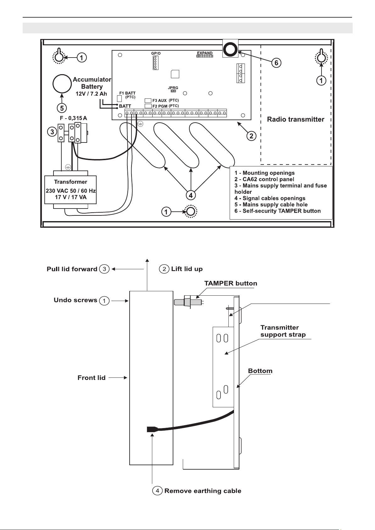
2.3 СА62 Alarm Control Panel Metal Box
Figure 1. Situation of СА62 alarm panel in metal box.
CA62 Control panel
Figure 2. Side view and mounting of universal metal box.
Page 7

Installation and Programming Manual - СА62 Alarm Control Panel 7
2.4 СА62 Alarm Control Panel Plastic Box
Figure 3. Opening the CA62 plastic box and template for wall mounting.
1 - Central support opening (behind PCB)
2 - Support openings
3 - CA62 Control panel
4 - Mains power supply terminal
Figure 4. Situation of СА62 control panel in plastic box.
5 - Main cable opening
6 - Additional cable openings
7 - Mains power supply opening
8 - Tamper button for box self-protection
Page 8
8 Installation and Programming Manual - СА62 Alarm Control Panel
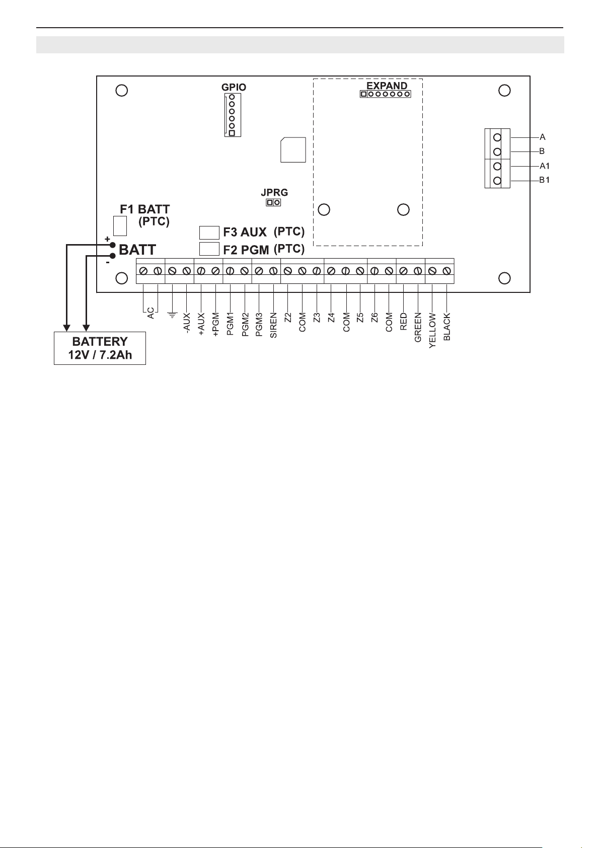
2.5 CA62 Alarm Control Panel Inputs and Outputs
Figure 5. CA62 control panel inputs and outputs.
Terminals description of СА62 control panel:
• AC - Power supply from 17V / 17VA mains transformer
•
• AUX - Power supply -PGM for detectors with consumption up to 1А
• +PGM - Power supply for additional devices with consumption up to 1А
• PGM1, PGM2, PGM3 - Programmable outputs
• SIREN - Siren programmable outputs (PGM4 by default)
• Z2, Z3, Z4, Z5, Z6 - Zone inputs (Z1 zone is in the keyboard))
• COM - Common mass of the zones
• A, В - Terminals for telephone line connection
• А1, В1 - Terminals for connecting a telephone set
• RED, BLACK - Keyboard power supply
• GREEN, YELLOW - Interface between the panel and the keyboard
• F1 BATT - Battery fuse 0.75А, Resettable (PTC)
• F2 PGM - Additional device 0.5А mains fuse, Resettable (PTC)
• F3 AUX - Fuse for powering sensors, programmable outputs and keyboards 0.5А, Resettable (PTC)
- “EARTH”
• BATT - Battery cables for accumulator with parameters 12V / 7.2 Ah
• JPRG - Jumper for hardware RESET and default parameters recovery
• GPIO - Interface connector for programming
• EXPAND - Terminal for expander modules (Voice dialer VD60)
Page 9
Installation and Programming Manual - СА62 Alarm Control Panel 9
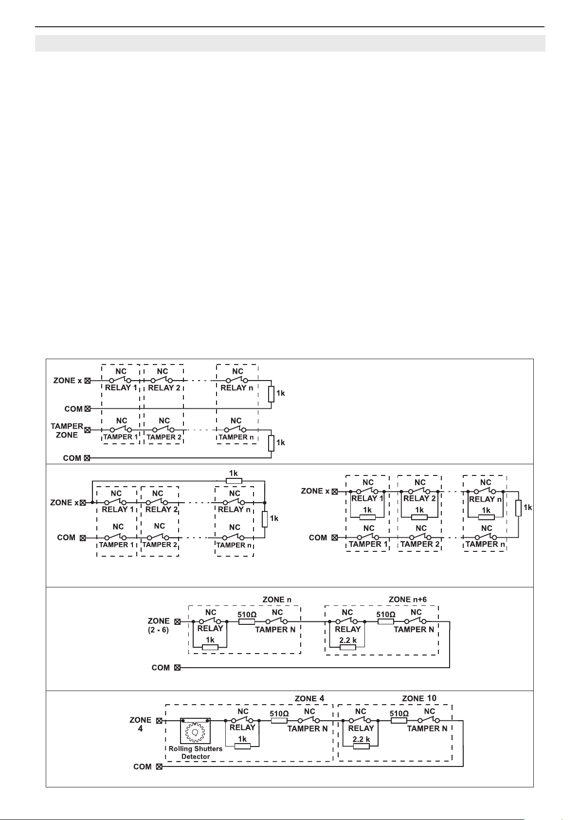
2.6 Connecting of Detectors to CA62 Alarm Control Panel
The security system is mounted with detectors with relay contacts.
Fire alarm detectors supplied with relay outputs can also be used.
There are three possible options for connecting of detectors to the CA62 zone inputs. The type of balancing for each
input is programmed separately at ADDRESSES 2zz6, where "zz" is the zone number - from 02 to 06.
The possible options for connecting the detectors and for balancing the zones are shown on Figure 6: a) Connecting
Detectors with One Balancing Resistor, b) Connecting Detectors with Two Balancing Resistors and c) Connecting Detectors with Three Balancing Resistors (zone doubling with connecting two groups of detectors/ zones to one input).
The zone doubling allows to the zones with numbers 2, 3, 4, 5 and 6 of СА62 control panel to be connected two groups
of detectors, as the rst group is terminated with 1 kΩ resistor, and the second - with 2.2 kΩ. When a zone doubling
is realized in the system, the number of the zone for the second group of detectors, represents the number of related
zone + 6.
Use the supplied 1 kΩ resistors to balance the zones. The balancing resistors are installed on the last detector of the
circuit. The zones, which shall not be used, are terminated with one 1 kΩ resistor at the terminals of the CA62 Control
Panel, irrespective of the chosen type of zone balancing. A second way for temporary termination of the unused zones
is as program them as 0.Unused on the respective address - see the description of ADDRESS 2010.
After the initial power up of the control panel, the zone balance type has to be programmed. By default only 1 balancing
resistor is used.
The hardware implementation of Zone 4 of the panel permits performance in pulse count mode, suitable for connecting
a rolling shutters detector. This mode counts short pulses - 2 to 4 ms for a period of 20 seconds. The rst pulse starts a
20-second countdown during which pulses are expected to be received. Their number is assigned at ADDRESS 2047 of
the engineer program. An alarm signal is emitted when this number is reached within the time of 20 seconds. Otherwise
the pulse counter will be zeroed after the time of 20 seconds expires.
Activating the pulse count mode will automatically start when a number other than 0 is keyed in at ADDRESS 2047 of
the engineer program. The connection option of a rolling shutters detector to ZONE 4 is shown on Figure 6 d).
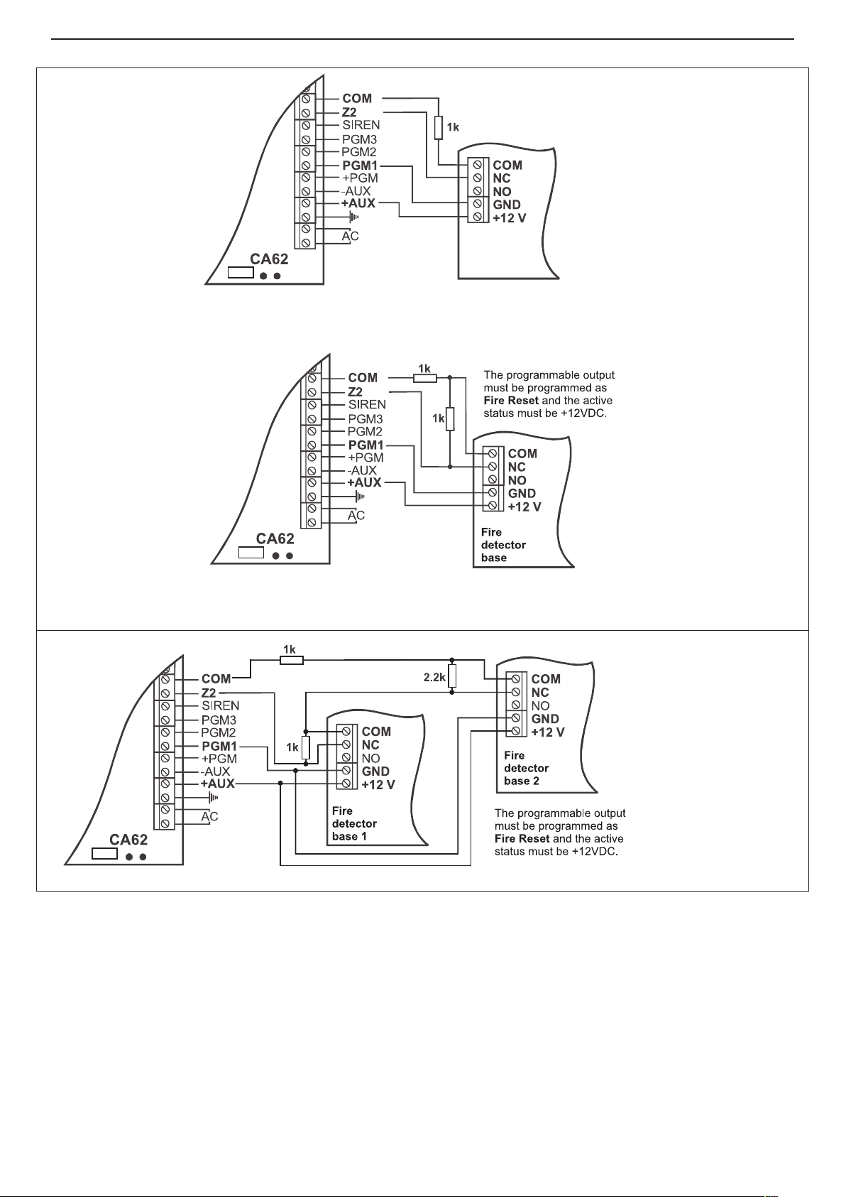
The possible options for connecting re detectors and balancing the zones are shown on Figure 7.
а) Connecting Detectors with
One Balancing Resistor
Connecting up to n detectors Connecting up to 4 detectors
b) Connecting Detectors with Two Balancing Resistors
c) Connecting Detectors with Zone Doubling
d) Connecting of rolling shutters detector to Zone 4, in zone doubling mode.
Figure 6. Options for connecting detectors to the CA62 control panel.
Page 10
10 Installation and Programming Manual - СА62 Alarm Control Panel
The programmable output
must be programmed
as and the active
status must be +12 VDC.
Fire Reset
Fire
detector
base
Connecting a re detector with one balancing resistor
Connecting a re detector with two balancing resistors
a) Connecting a re detector with a relay in the base
*
b) Connecting of two re detectors to a doubling zone.
Figure 7. Connecting a re detector to CA62 alarm control panel.
* You can use also
two R=510Ω (one R is
connected to every fire
detector), instead of
one R=1k.
Page 11
Installation and Programming Manual - СА62 Alarm Control Panel 11
2.7 Connecting of Peripheral Devices to СА62 Alarm Control Panel
2.7.1 Connecting LED and LCD Keyboards to CA62 Alarm Control Panel
Two types of keyboards can be used to control and program the СА62 alarm panel:
• LED keyboards -models LED61, LED62, LED63VG SE
• LCD keyboards - models LCD62, LCD62B, LCD63, LCD63SE, LCD64
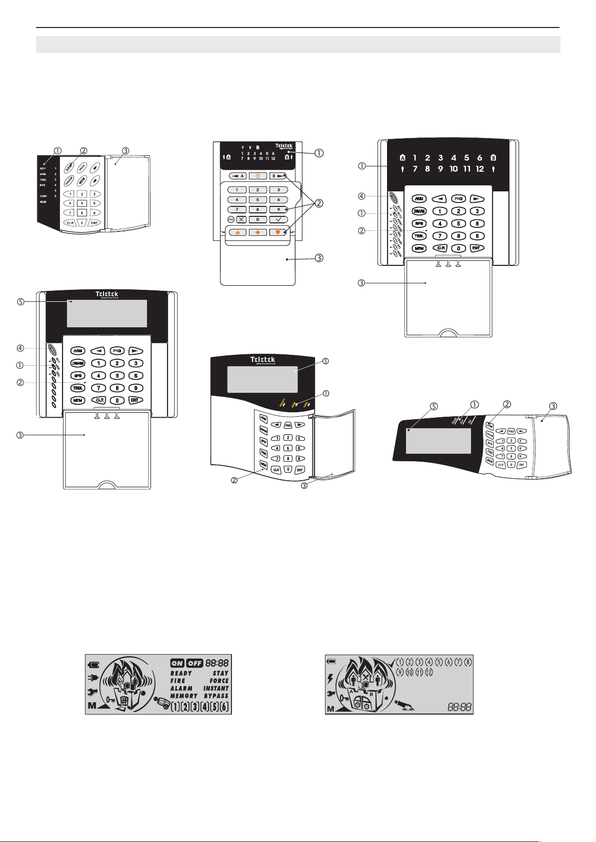
LED61
LED62
LCD63, LCD63SE
Figure 8. Basic view of LED and LCD keyboards.
Symbols to Figure 8:
. Status LED indication.
. Buttons for programming and controlling of CA62 control panel.
. Protective cover (open).
. Microphone.
. LCD display.
Attention: The LCD display is different for the listed keyboard models:
LCD62B / LCD64
LED63VG SE
LCD62
Models: LCD62, LCD62B, LCD63VG Model: LCD63SE, LCD64
For detailed description for indication and operation of all keyboard models refer to their individual manuals.
Page 12
12 Installation and Programming Manual - СА62 Alarm Control Panel
Keyboard:
ZONE 1
DETECTORS WIRES
CA62 control
panel terminals
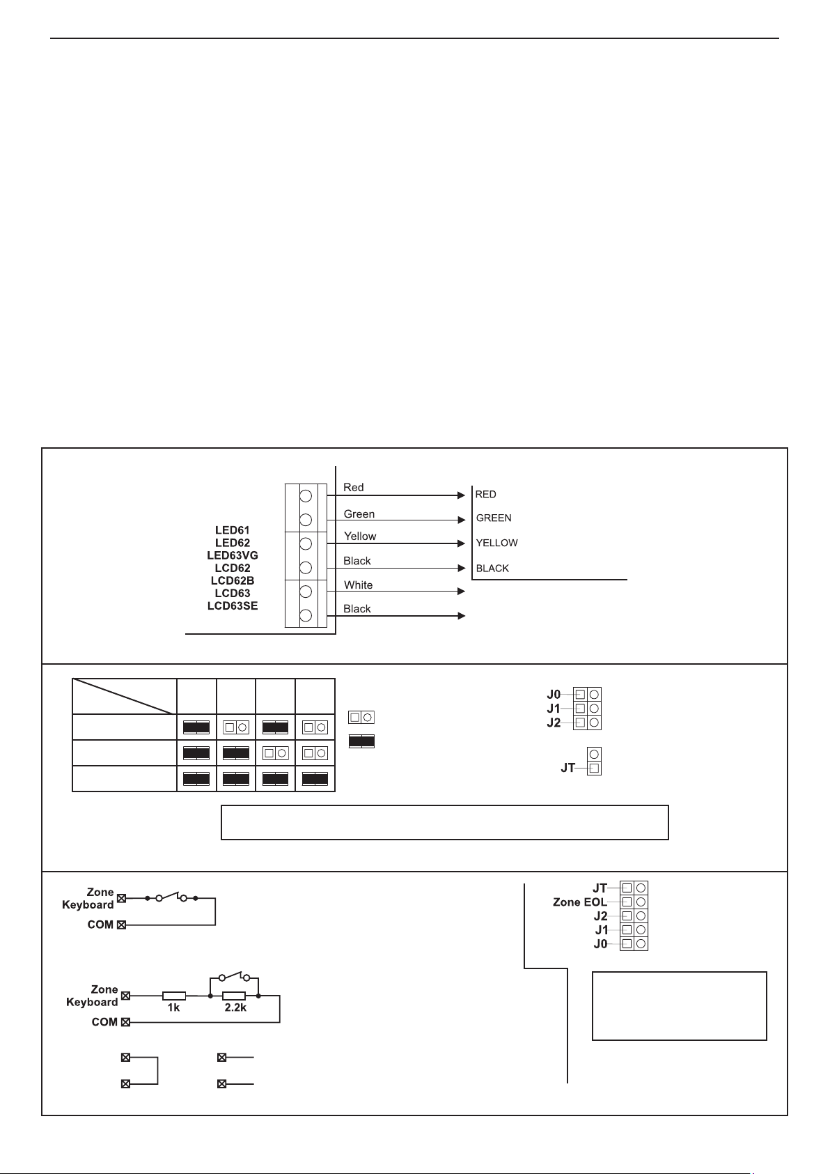
All keyboard models are factory equipped with 4 terminals for connecting to СА62 control panel and two other terminals
for connecting to ZONE 1. Note: At LED61 keyboard, the input for ZONE 1 is equipped with two 10-cm long wires - black
and white for the bus connection. These terminals are marked with the respective colors.
The colors must be observed when connecting the keyboards to the СА62 Control Panel (see Figure 9). Note:
The connection in the connection below is principled. Note that in some keyboards the terminals for connecting to
ZONE 1 could be situated above the terminals for connecting to the control panel.
The zone cables are white and black in color. The zone in the keyboards HAS NOT to be balanced (except LED62
and LED63VG SE keyboards - the keyboard zone can be balanced with setting the ZONE EOL jumper, see the
jumpers explanation on Figure 10b). The zone in all model keyboards HAS NOT to be programmed as double
zone also. When more than one keyboard are connected to the control panel, each keyboard have to be assigned with
individual zone number - 1 or 7. Activating any keyboard zone shall be regard as an activation of ZONE 1 or ZONE 7,
according the individual programming.
No more than 4 keyboards (irrespective of their type) can be connected to one control panel. Each keyboard must be
assigned an individual address, by placing the jumper on the keyboard at its respective place (see Figure 10а). The
individual address ensures TAMPER event identication, whenever the TAMPER switch of the respective keyboard is
turned on.
The individual address of each keyboard is assigned with the help of a jumpers. Following the table (see Figure 10а)
the respective address could be programmed. The individual address of each keyboard in the system can be checked
at ADDRESS 7000 from the Engineer menu (see page 47).
The JT jumper must be placed where only one keyboard has been connected. Where more than one keyboards are
connected, the JT jumper should be placed on the most distant one. The JT jumper is set by default.
The cable connecting the LED61 Keyboards to the CA62 Control Panel must be no longer than 250m and have a crosssection of no less than 0.25mm.
Jumper
Address
J0
J1
J2
(SE)
LCD64
Figure 9. Connecting keyboards to CA62 control panel.
1 2 3 4
Legend:
- The jumper is removed;
- The jumper is set
NOTE: The JT jumper must be set in the most far unit in the bus.
Figure 10a. Table for keyboard address programming.
The LED keyboard zone is not balanced.
The jumper Zone EOL is removed.
The zone has two states:
• zone closed (the switch is closed)
• zone open (the switch is open)
Jumper location for
keyboard models:
LED61, LCD62,
LCD62B, LCD63,
LCD63SE, LCD64
Jumper location
for keyboard
models:
LED62
LED63VG SE
NOTE: The JT jumper
must be set in the most
far unit in the bus.
1)
2) 3)
The LED keyboard zone is balanced.
The jumper Zone EOL is set.
The zone has three states:
• zone closed (the switch is closed) - item 1
• zone open (the switch is open) - item 1
• tamper - items 2 and 3
Figure 10b. Jumper location and zone balancing of LED62 and LED63VG SE keyboards.
The parameters and the functions of the buttons for each keyboard can be programmed at ADDRESSES 70xx, according to the set with jumper address of the keyboard.
Page 13
Installation and Programming Manual - СА62 Alarm Control Panel 13
* The JT jumper must be set in
the most far unit on the bus.
LED indication:
- green - the card is recognized or
required action is done,
- red - the card is not recognized or
required action is rejected,
- yellow (LED blinks) - ready.
Internal structure of built-in PGM
PGMx terminal
Permissable currents:
- from +12 V - up to 10 mA
- towards GND - up to 100 mA
The output activates for 2
seconds after the recognised
card is drown back.
Two color LED indicator
Lock
Mounting openings
Signal cables
openings
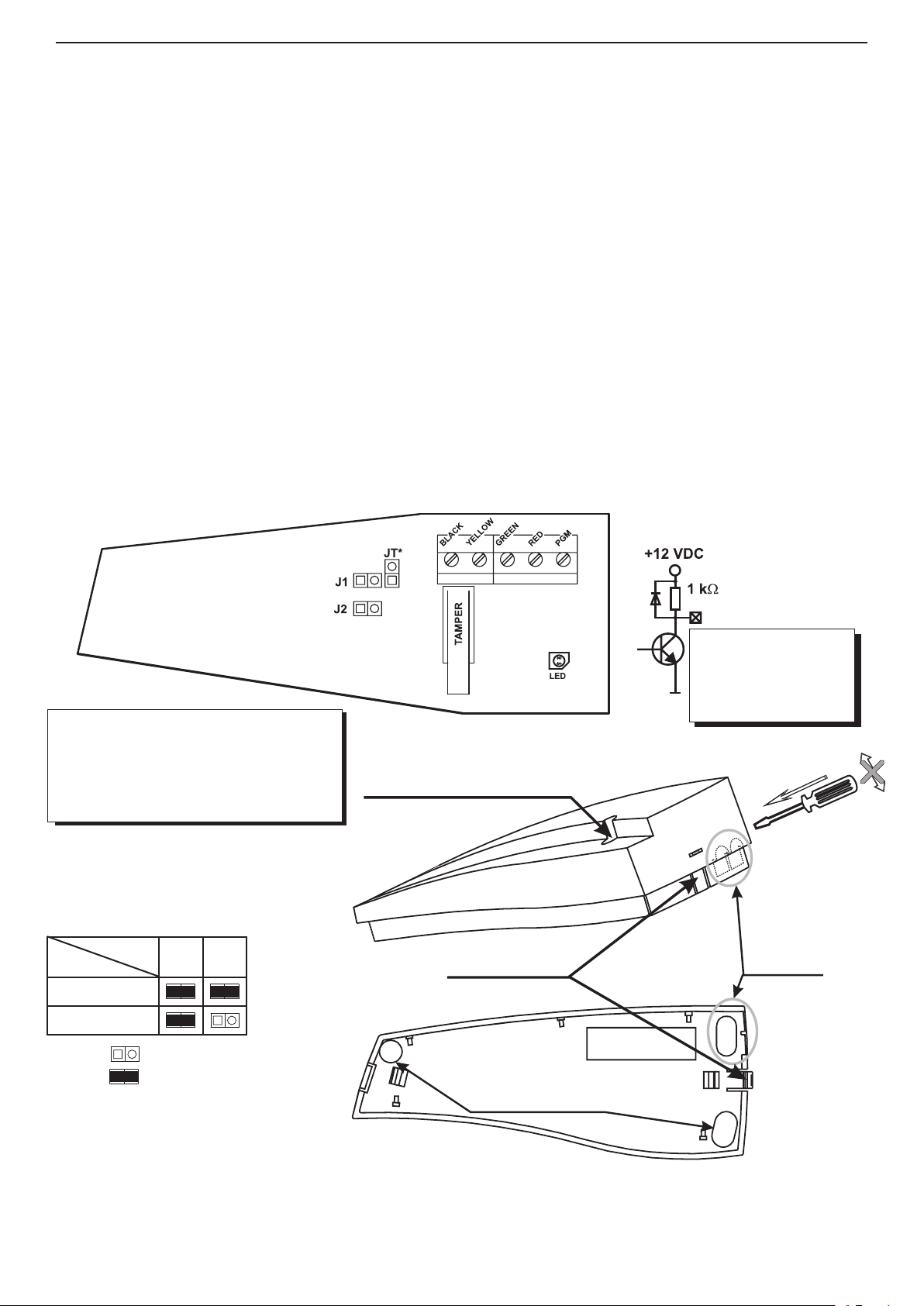
2.7.2 Connecting of Proxi Reader PR62 to CA62 Alarm Control Panel
The PR62 proximity card reader was designed to control security in the systems integrated within the CA62 Control
Panel. The excellent card reading distance, the triple color indications, supplemented by the sound indicator, the integrated output, as well as the ne design, all make the PR62 any attractive supplement to the security system.
The PR62 can be connected to the terminals RED, GREEN, YELLOW and BLACK of the CA62 together with the
mounted keyboards. Up to two proximity readers can be included within one security system. Programming the various
addresses onto the readers will provide identication by the TAMPER of each of these. The Table for Address Programming is provided on Figure 11.
The proximity-card enables to arm and disarm the system, as well as to control the electric lock (key-switch) via inte-
grated output. The internal structure, and the permissible output currents, are provided in Fig. 11.
It is possible that only proximity-card readers be included in a system without having an installed keyboard. In such
systems this would hinder current programming of parameters and cards, as well as Log Review and Technical Trouble
indications. Portable LED or LCD type keyboards can be used to accomplish such tasks.
Up to 24 cards can be assigned to one security system - one card for each of the 20 users and 4 cards for the Managers
in the system.
The Managers in the system are allowed to program the performance of the cards.
Arming and/or disarming rights must be assigned for the respective user code.
The user may not be designated a code combination. In such case the only means to control the security system would
be the proximity-card.
The parameters of the proximity card readers in the system can be programmed at ADDRESSES 71хх, according to the
set with jumper address of the proxi reader.
Setting the address of PR62
Jumper
Address
1 2
J1
J2
Legend: - The jumper is removed;
- The jumper is set
PPPProxi CA62
Figure 11. PR62 Proximity card reader installation and connection diagram.
Page 14
14 Installation and Programming Manual - СА62 Alarm Control Panel
PGMx terminal
Permissible current:
- from +12 V - up to 10 mA
- towards GND - up to 100 mA
For SIREN output the
current supplied to GND
is up to 1A.
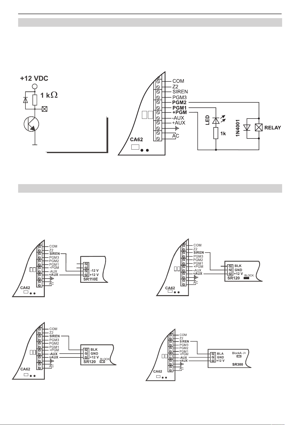
2.8 Using of PGM1, PGM2 and PGM3 Programmable Outputs
The СА62 Alarm panel PGM1, PGM2 and PGM3 outputs have a programmable active level. This allows them to be used
to transmit control signals towards external devices (e.g. a block siren input) or to directly control low-powered external
devices (e.g. relays, LED, etc.).
The internal structure of all PGMs is the same and is shown on Figure 12 a).
Figure 12 b) shows the connection of the relay and a light-emitting diode to the PGM. The active level of this connection
is low.
Figure12. а) Internal structure of Figure12. b) Controlling light-emitting diode and
programmable PGMx output relay using PGM1 and PGM2 outputs
2.9 Using SIREN Programmable Output (PGM4)
The СА62 Alarm panel SIREN output has a programmable active level. With the default conguration the output is
with SIREN and POLARITY set attributes, which can be programmed at ADDRESS 3041. The output is activated in
case of alarm event in the system.
The internal structure is identical to the one shown in Figure 12 a) and we should point out that the transmitter can pass
through to GND electricity of up to 1 A.
Figure 7 shows how to connect SR110, SR120, SR200 and SR300 sirens using the SIREN output.
The BLOCK jumper
in SR120 (BL in SR200)
must be set on.
a) Connecting SR110 using a double-wire b) Connecting SR120/SR200
using a double-wire
The BLOCK jumper
in SR120 (BL in SR200)
must be removed.
The jumper BlockA -/+ determines the level of
the block signal: set jumper - high level (12V);
removed jumper - low level (GND)
c) Connecting SR120/SR200/SR300 using triple-wire.
Figure 13. Controlling sirens using SIREN output.
Page 15
Installation and Programming Manual - СА62 Alarm Control Panel 15
Telephone line
Telephone device
2.10 Connecting the CA62 Built-in Digital Communicator
The telephone line is connected to A and B terminals on the
CA62 Control Panel with no requirements to observe polarity
(Figure 14). The telephone device is connected to A1 and B1
terminals on the CA62 Control Panel with no requirements
to observe polarity (Figure 14). The parameters of the digital
communicator are engineer programmed. It is not necessary
to install additional components if the built-in communicator
is not to be used.
You can test the Built-in Digital Communicator working efciency at ADDRESS 0023 described on page 23.
Figure 14. Connecting the CA62 built-
in communicator
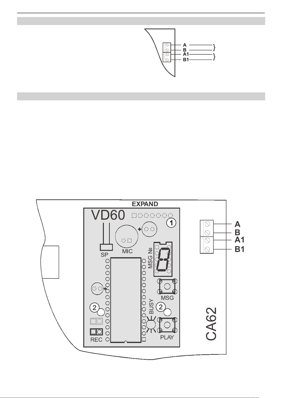
2.11 Installing of VD60 voice dialer to CA62 Alarm Control Panel
The “VD60” Voice Telephone Dialer module supplements the СА62 Alarm Control Panel, which serves to transmit alarm
event messages to the user, under the form of eight pre-recorded voice messages, of up to 4 sec. each. Two message
types are supported - by zone or by event (see description of ADDRESS 6035).
Turn off the power supply in order to connect the PCB of the voice telephone dialer to the EXPAND socket of the CA62
Control Panel (1). Fix the PCB onto the pre-mounted plastic spacers (2). The telephone line should be connected to
terminals A and B of the СА62 Control Panel. Polarity need not be observed.
The telephone device can be connected to terminals A1 and B1 of the СА62 Control Panel with no need of observing
polarity.
The voice dialer can simultaneously operate with the built-in digital communicator.
The dialer has one LED status indicator - PLAY/RECORD and BUSY, and one single digit LED display indicating the
number of the current message. Use the MSG key to switch-over between messages. Use the PLAY key to reproduce
messages when the REC jumper is turned off, or to record when it is turned on. You can record voice messages at AD-
DRESS 6030, as use the detailed working algorithm described at APPENDIX Е. A speaker (8-16 ohms) for listening to
recorded messages can be connected to the SP socket.
The voice dialer parameters can be programmed in the engineering menu at ADDRESSES 603х.
Figure 15. Installing the VD60 Voice Telephone Dialer.
Page 16
16 Installation and Programming Manual - СА62 Alarm Control Panel
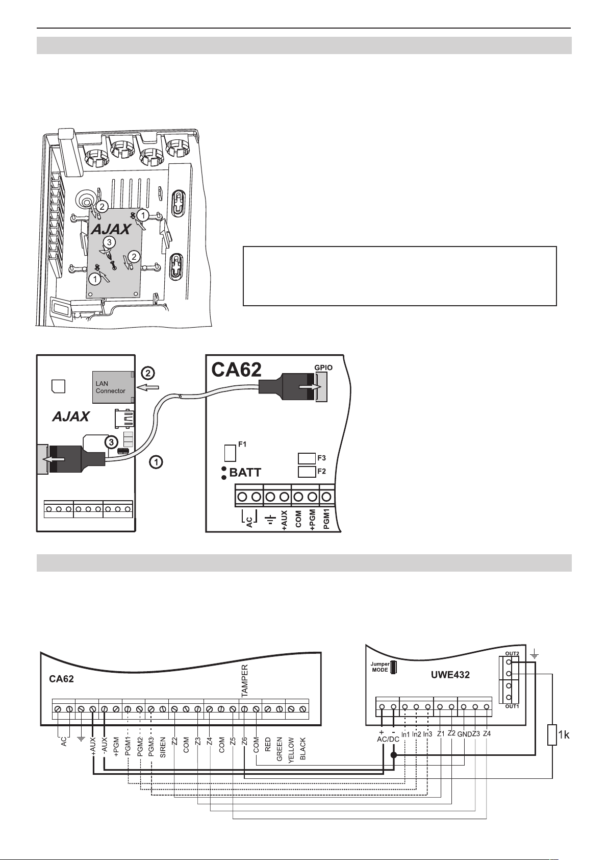
2.12 Installing of AJAX LAN Module in CA62 Alarm Control Panel
AJAX Module is an additional accessory for built-in installation in CA62 or any other security or re control system. It
transmits the system status to Monitoring centre or to the User via Internet. The AJAX module enables easy monitoring
and transmitting of alarm events occurring in the security system to existing Monitoring centre using standard monitor-
ing software.
For more information please refer to the distributor of this equipment.
For the installation of AJAX LAN module in the CA62 universal plastic box
refer to sequence shown in Figure 16 as follow the steps:
- Break off the pins from the plastic box.
- Fix the mounting holes to the respective pins and carefully push down.
- Fix the module to the plastic box with the screw from the spare parts kit.
Figure 16. Installing of AJAX LAN Module.
ATTENTION: The connecting between AJAX LAN module and
CA62 alarm control panel MUST BE done only with power
supply OFF and set RESET jumper on the AJAX module!
For the connection between AJAX LAN module and CA62 alarm control panel refer to
Figure 17, as follow the steps:
- With Power supply OFF, connect the
AJAX module to the CA62 by means the
interface cable (Note: the interface cable is
not included in the spare parts kit for CA62.)
- Connect LAN cable for Internet connec-
tion.
- Place a reset jumper.
- Turn the Power supply ON and wait
for 5 seconds in order to congure and to
obtain the default factory parameters.
- Remove the RESET jumper.
Figure 17. Connecting of AJAX LAN
module to CA62.
2.13 Connecting of UWE432 Universal Wireless Expander to CA62 Alarm Control Panel
UWE432 is a universal device for expanding existing wired alarm security systems. UWE432 communicates by means
of two-way radio connection with the AVA series wireless devices. The UWE432 supports up to 32 AVA series wireless
devices. Attention: The panel should be programmed to operate in double zone connection mode (at addresses
20х6, х - from 2 to 7, "4. Doubling" parameter is set). It is obligatory to set a jumper on connector MODE at
UWE432 main board!
Figure 18. Connecting UWE432 universal expander to CA62 alarm control panel.
Page 17
Installation and Programming Manual - СА62 Alarm Control Panel 17
In1 - Input for resetting wireless re detectors (time for reset ≥ 2 seconds), the active state towards GND is 0V; In2 -
Input for wireless siren control (time for reset ≥ 2 seconds), the active state towards GND is 0V; In3 - Used only in case
RC102TE remote control is enrolled to UWE432 receiver module; this is an input for monitoring of the control panel
status; Out1 - Relay output (NO) for Low Battery and Lost Device state of wireless devices; Out2 - Relay output (NC) for
TAMPER state of wireless devices and the UWE432 box; Connect to a TAMPER type zone of the control panel.
More information about UWE432 functions and programming you can nd in its installation instructions.
2.14 Powering up the CA62 Alarm Control Panel
The system should be powered-up only after it is installed and all necessary devices have been connected - control
panel, keyboard, detectors, etc.
Follow the next installation procedure when power-up the CA62 system for the rst time:
➢ Set the JPRG jumper (Figure 5) on CA62 control panel, in order to congure the control panel default parameters (the factory settings).
ATTENTION: The CA62 alarm control pane supports 4 different default congurations. With every full hardware
system reset (jumper JPRG is set) the parameters for default conguration 0 will be set. The special of the
default conguration 0 is that all zones in the system are disabled (the 0.Unused type is set for all), the zone
balancing is with one resistor in the circuit and so on. For details for settings of the default system congura-
tion 0, see SECTION 2 - Programming.
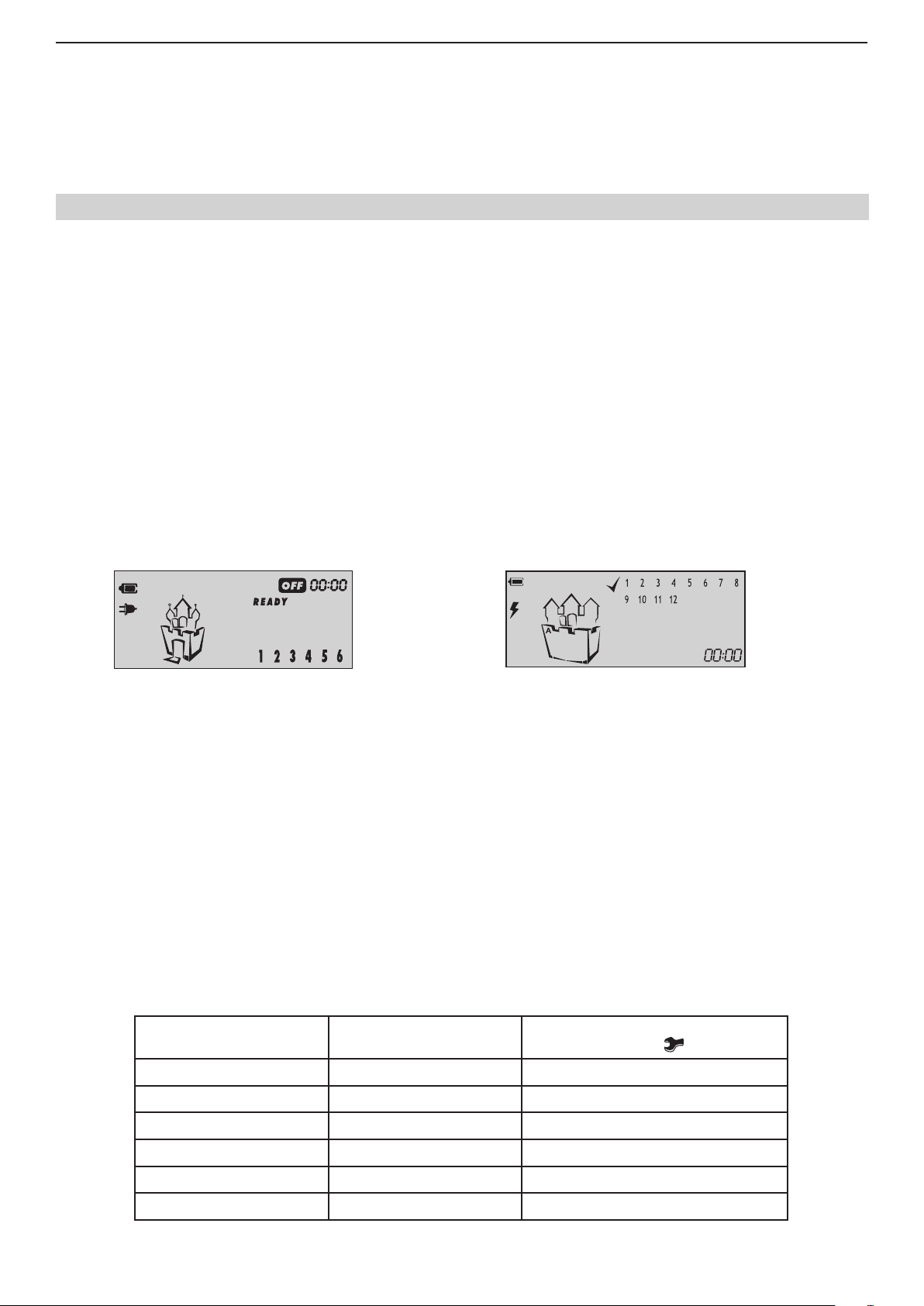
➢ Supply 220V mains power. The keyboard emits a short sound signal or series of short beeps according
the used model. In case of a LED keyboard the light-emitting diodes on the display blink. When a LCD
keyboard is used the display will light up in blue or orange.
➢ Remove the JPRG jumper. In normal operation mode - all detectors in the security system are inactive
and there are no violated anti-TAMPER chains - the RDY LED lights up in green. The station now has been
programmed with the default conguration 0.
If you operate with LCD keyboard the display is looking different according the model:
Models: Model:
LCD62, LCD63SE
LCD62B, LCD64
LCD63
➢ Use the red (+) and black (-) cables to connect the battery to the station.
All light-emitting diodes will blink and a sound signal will be heard where the keyboard is open or incorrectly connected.
Where there is an open zone or an open TAMPER for any zone, the LED for the respective zone (at LCD keyboards the
zone number is enclosed in brackets) together with the MEMORY or TAMPER LEDs on the display will light up (at LCD
keyboards lights up TRBL LED and symbol "wrench" is blinking).
ATTENTION! An open anti-sabotage chain (TAMPER) in the security system will sound the siren. To stop the
siren enter Manager code 0000. The respective zone LED remains permanently lit whereas the TAMPER LED will
blink. Remove the failure - the TAMPER LED remains permanently lit. Enter code 0000 again to clear the alarm
event from the memory.
2.14.1 Technical Trouble Indication
Any technical trouble in the panel will light up the Trouble indicator (blinking TRBL LED and/ or symbol “wrench” according of the keyboard model). To view these problems enter the 0000 manager code and single-press ENTER. The display
will indicate a list of current problems. The indications and their meaning are shown in the table below:
LED Keyboard
LED lighting up
B
C
D
E
F
G
LCD Keyboard
Digit enclosed in brackets
(1)
(2)
(3)
(4)
(5)
(6)
Technical trouble
(LED or symbol
No 220 V power supply
Battery low
Fuse burned
No telephone line
No communication available
Active TAMPER within the system
is blinking)
Trouble mode indication (Technical Trouble)
Page 18
18 Installation and Programming Manual - СА62 Alarm Control Panel
SECTION 2: PROGRAMMING
Programming the Software Parameters of СА62 Alarm Control Panel
The system can operate with 4 or 6 digit codes. If a 6 digit code is set at ADDRESS 1001 at the end of every valid code
an extension "00" is automatically added. Next a new 6 digit code combination can be programmed.
The respective parameters can be congured from a LED or LCD keyboard or remotely by means of connected to the
system a personal computer via a telephone using the ProsTE Software.
Symbols used in this manual
For more clear presentation of the programming with the two types (LED and LCD) keyboards and for easy performance of the information in this manual, the following symbols for indicating of active (enabled) and inactive (disabled)
parameters in the engineering programming menus are used:
Indicator Parameter state LED LCD
ZONES
Keyboard programming
Entering the system engineer code will initiate the CA62 Alarm System programming mode for the engineer parameters. After restoring the default parameters (system RESET) the engineer code will remain 7777.
When you enter the engineer programming menu the indication of the used keyboards will be as follows:
- LED Keyboards - the LEDs RDY (green), ARM (red), TRBL (yellow) and BPS (red) are blinking together. At LED62
keyboard the symbols “lighting”, “wrench” and “sheet” are blinking together.
- LCD Keyboards - the LEDs RDY (green), ARM (red) and TRBL (yellow) are blinking together. The
blinks together with symbol . At LCD63SE keyboard the symbol is blinking, and at the middle tower of the castle
the symbol is steady.
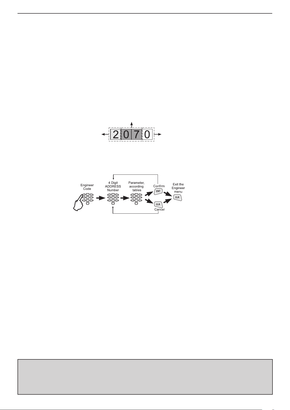
At LCD type keyboards, after entering engineer programming mode the symbol
clock. Every entered digit of the ADDRESS stop blinking and stays steady, the symbol next to it will be continue blink-
ing, which means, that the system is waiting for entering the next digit of the 4 digit ADDRESS.
After entering 4 digit number of a valid ADDRESS a conrmation sound signal will be heard.
After entering of a 4 digit ADDRESS the engineer can program the respective system parameter. Use the provided in
this section tables with detailed descriptions of all available ADDRESSES in the system. You can use also the tables in
SUPPLEMENT A for quick reference. All entered parameters have to be conrmed with pressing the ENT button. When
reviewing the programmed parameters it is recommended to exit any given address by single pressing the CLEAR
button. This function will leave the introduced parameters unchanged. In case the programmer is disoriented in the en-
gineer menu, it is recommended to exit the menu by double clicking the CLEAR button and to begin programming the
station parameters from the start.
ATTENTION: The CA62 Alarm System engineer parameters programming mode can begin only when the system is in disarmed mode! When there are several (up to 4) keyboards connected to the control panel in the system you can program parameters only from this one where the engineer code has been entered. The indication
of all other keyboards will show that the system is in engineer programming mode, but you can not program
parameters with them.
Active (enabled parameter)
Inactive (disabled parameter)
B - Lights on
- Lights off
(1) - Number enclosed in brackets
1 - Number without brackets
symbol
starts blinking at the place of the
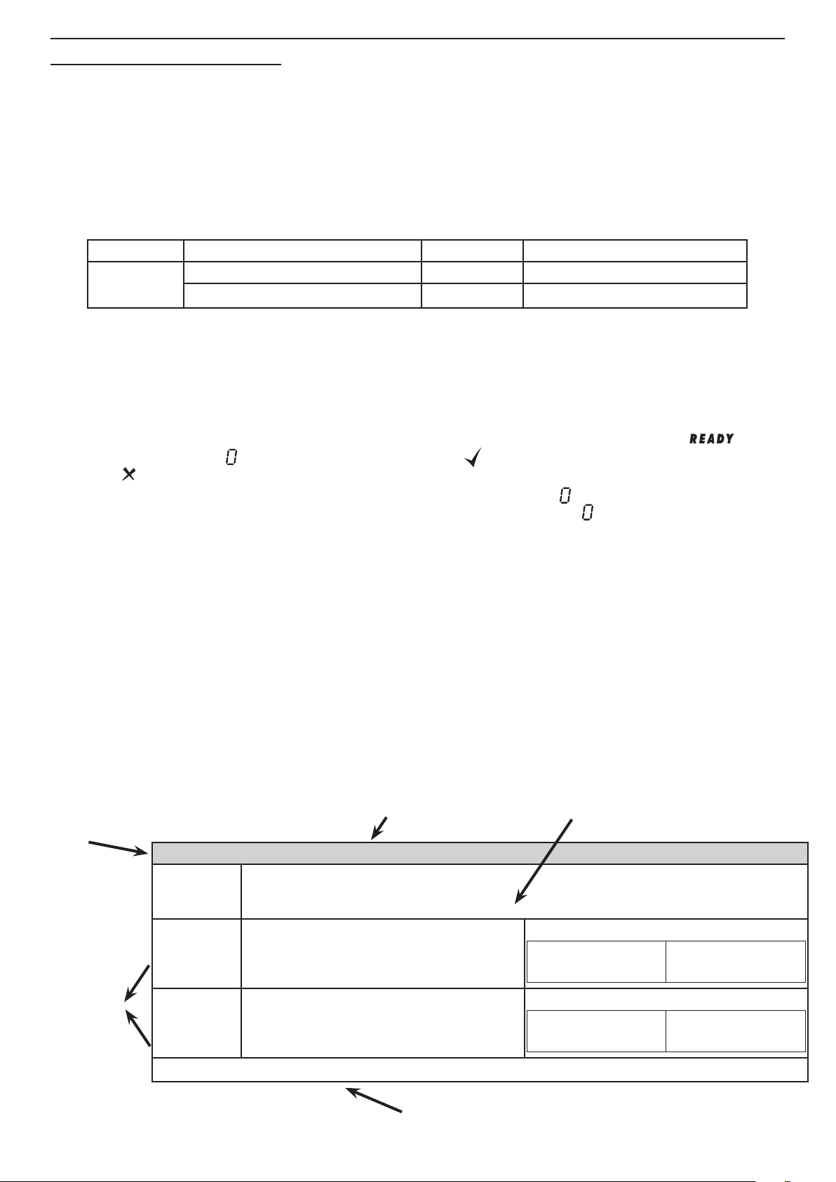
How to read the information in the tables below:
ADDRESS
Number
ADDRESS 0001 - HARDWARE RESET ENABLE
Reset
Enable
NO The hardware RESET is disabled.
Programming
menu param-
eters
YES The hardware RESET is enabled.
Default settings
Disables or enables the hardware RESET of the alarm station. Specialized service is
required where the hardware RESET is disabled and the engineer code is obscure.
The parameter status can be changed with pressing of random button of the keyboard.
- YES
Name of the programming menu
Description of the programming menu
Indication
LED
Indication
LED
Default conguration settings for that programming menu
(1) (2) (3) (4) (5) (6)
LCD
1 2 3 4 5 6
LCD
Page 19
Installation and Programming Manual - СА62 Alarm Control Panel 19
For easy nding the information in the programming tables, the ADDRESSES are organized in 7 separate sections:
The rst digit of the ADDRESS structure describes:
0 - Programming the engineer and common system parameters;
1 - Programming the access codes in the system;
2 - Programming the zone parameters in the system;
3 - Programming the PGM outputs in the system;
4 - Programming the partitions in the system;
6 - Programming the parameters of the communication devices in the system;
7 - Programming the parameters of the peripheral devices in the system.
The second and the third digit in the ADDRESS structure logically separate the unit number for every sec-
tion - for example 01, 02 and so on are zone numbers. The same principle is right for the sections for programming the parameters of access codes, zones, PGM outputs, partitions, communication and peripheral devices
in the system.
The forth digit in the ADDRESS structure is the number of a parameter for a specic system resurse.
Example for ADDRESS structure reading:
Zone number
Section for zone
programming
Besides the information for activating and deactivating of the system parameters, for some menus are shown and con-
crete examples for the status and indication of the LCD keyboards.
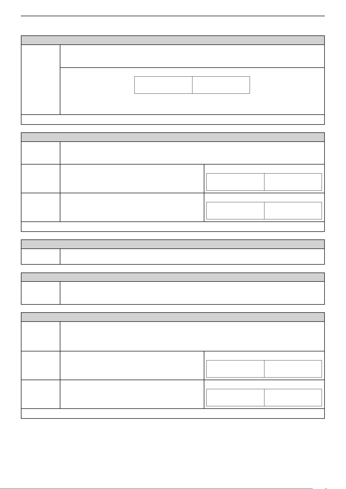
Basic sequence in operation when programming the Engineer menu:
Remote programming of CA62
To access a ProsTE software program system requires an ID number and a station ID number. After restoring the default
parameters these numbers will be the same and are 1234. In order to provide access to the system from the central
station enter the correct number of the central station at ADDRESS 6901 (PC ID).
A 24-hour period automatically begins after default parameters are restored during which the UDL communication with
the system is enabled even when the "ring number" parameter is zeroed at ADDRESS 6904 (with set 0 number, the
UDL communication will starts after receiving of 7 rings). After the initial 24-hour period, the UDL communication with the
system will enabled only if the "ring number" parameter set at ADDRESS 6904 is different from zero.
If during the 24-hour period the system is power off (together the main power supply and the battery), at the next power
on the started already 24-hour period will be disabled and the UDL communication will be enabled only if the "ring
number" parameter set at ADDRESS 6904 is different from zero.
If during the 24-hour period the engineer enters the ADDRESS 6903 and exit it by pressing the ENT button (with conr-
mation), then the 24-hour time period and this case will be disabled.
Detailed working instructions for the ProsTE software program are provided in the built-in Help les. The connection
between the local computer and the CA62 control panel is via a specialized module (the module is not included in the
CA62 equipment and is sold as a separate product.)
The details listed in this manual apply to all parameters for remote system programming.
Parameter for
programming the
zone type
Programming of Default Congurations in the CA62 Alarm Control Panel
The system supports 4 separate default congurations with set parameters. Enter a number of default conguration
(0-3) at ADDRESS 1000 in the engineer programming menu - see item 1. User and Manager Codes Programming. At
SUPPLEMENT B are shown examples for using the default congurations in the system.
ATTENTION: With realizing full hardware reset, in the system automatically will be set the
default conguration 0 parameters!
The default conguration 0 parameters are described in details in Table 1 (SUPPLEMENT
A) and they are described in ADDRESSES tables below.
Page 20
20 Installation and Programming Manual - СА62 Alarm Control Panel
0. ENGINEER PARAMETERS AND COMMON SETTINGS
ADDRESS 0000 - CHANGING THE ENGINEER CODE
A new access code to the alarm station engineer parameters can be assigned at this address.
Note: If the 6-digit long access code is set, the combination "00" automatically will be added at the end
of all valid codes in the system (see also the description of ADDRESS 1001).
Engineer
code
The light-emitting diodes 3, 4, 5 and 6 on the keypad display light up. These go out one by one as the
new code is entered. The new code has to be entered a second time.
Default settings
ADDRESS 0001 - HARDWARE RESET ENABLE
Reset
Enable
NO The hardware RESET is disabled.
- 7777
Disables or enables the hardware RESET of the alarm station. Specialized service is required where
the hardware RESET is disabled and the engineer code is obscure.
The parameter status can be changed with pressing of random button of the keyboard.
LED
Indication
LCD
1 2 (3) (4) (5) (6)
LED
Indication
LCD
1 2 3 4 5 6
Indication
YES The hardware RESET is enabled.
LED
Default conguration
ADDRESS 0002 - RESTORING DEFAULT PARAMETERS (SOFTWARE RESET)
Default
settings
ADDRESS 0003 - RESTORING DEFAULT MANAGER CODE (PARTIAL SOFTWARE RESET)
Partial reset
ADDRESS 0010 - AUTHORITY TO ARM USING A ONE PUSH-BUTTON (QUICK ARM)
Quick ARM
Enable
PARTITION AQuick Arming of PARTITION A without legal user
Restoration of default settings of the station. The buttons 1, 2, 3, 4, 5, 6 are pressed in succession and
conrmed with the ENTER button.
Restoration of the default manager code. Buttons 1, 2, 3, 4, 5, 6 are pressed in succession and conrmed with the ENTER button.
The station restores the default 0000 manager user code.
A quick Arming mode using one button, without need to enter a valid user code is assigned at this ad-
dress. The assigning can be done for PARTITION A, PARTITION B or for both partitions.
The parameter is activated with pressing a digit number corresponding to the partition number - 1 for
PARTITION A and 2 for PARTITION B. Next pressing of the button will deactivate the parameter.
code.
- YES
Indication
LED
LCD
(1) (2) (3) (4) (5) (6)
LCD
(1) 2 3 4 5 6
PARTITION BQuick Arming of PARTITION B without legal user
code.
Default conguration
- PARTITION A, PARTITION B
Indication
LED
LCD
1 (2) 3 4 5 6
Page 21

Installation and Programming Manual - СА62 Alarm Control Panel 21
ADDRESS 0011 - AUTHORITY CODE DURING AMBUSH (AMBUSH CODE)
Ambush
Code
NO Disabled ambush code.
Enabling/ Disabling the ambush code in the system. The parameter status can be changed with pressing of random button of the keyboard.
LED
Indication
LCD
1 2 3 4 5 6
Enabled ambush code. The code is made up by adding 1 to a legal user code. There is no carrying over for
YES
Default settings
ADDRESS 0012 - ENABLED KEYBOARD BLOCKING IN CASE OF ACCESS CODE ERROR
Enable keypad block
NO No keyboard blocking in case of wrong code entry.
codes ending in the gure 9.
For example, the ambush code for 1234 is 1235, and
for 9999 it is 9990.
- NO
Enabling/ Disabling blocking the keyboards buttons in case of wrong code entry. The parameter status
can be changed with pressing of random button of the keyboard.
LED
LED
Indication
Indication
The keyboard buttons will be blocked for 30 sec. if three
YES
Default settings
ADDRESS 0013 - TECHNICAL TROUBLE INDICATION MASK
Trouble
mask
wrong codes are entered in sequence - for 30 seconds
the keyboard buttons are disabled, and a continuous
sound signal is heard.
- NO
The mask for sound indication (two short beeps in every 20 seconds) from the keyboard in Technical
Trouble mode is assigned at this address.
The trouble indication mask is enabling with pressing a button with the respective number from 1 to
6 - see item 2.14.1 for the trouble indication in the system. Pressing the button with the same number
again will disable the trouble indication mask for the respective technical problem.
Only those LEDs whose numbers correspond to technical problems for which sound indications are
available will light up on the display at the end of the procedure. The set parameters are conrmed with
pressing the ENT button.
The procedure for enabling/ disabling the trouble mask indication are the same for all types and mod-
els CA62 keyboards.
Example for disabling a trouble indication mask using LCD62 keyboard:
LED
Indication
LCD
(1) (2) (3) (4) (5) (6)
LCD
1 2 3 4 5 6
LCD
(1) (2) (3) (4) (5) (6)
1. АС Loss Loss of 220 V mains supply.
2. ВАТТ
Low
3. Blown
Fuse
4. No Tel.
line
5. СОММ
Error
6. TAMPER Activated TAMPER within the system.
Default settings
Drop in battery charge, no battery or burnt out F1 battery fuse.
Burnt out PGM fuse.
Loss of telephone line.
Central station communication failure.
- AC Loss, ВАТТ Low, Blown Fuse, No Tel. Line, СОММ Error, TAMPER
Page 22
22 Installation and Programming Manual - СА62 Alarm Control Panel
ADDRESS 0014 - 220 V AC POWER SUPPLY FAILURE INDICATION
Enabling / Disabling for the programming of time delay indication in case of 220 V AC power supply
220 V AC
failure
NO
failure. The time delay is in the range 0 - 180 min and is set on address 0018.
The parameter status can be changed with pressing of random button of the keyboard.
* The time delay set is valid for soft. rev. 4.3 and higher. If the soft. rev. of your control panel is
4.2 or lower, "YES" parameter sets 30 min time delay for power supply failure indication.
Instant indication for 220 V AC power supply failure
displayed on keyboards and message transmission via
digital communicator.
LED
Indication
LCD
1 2 3 4 5 6
Enable time delay indication for 220 V AC power
supply failure displayed on keyboards and message
YES
Default settings
ADDRESS 0015 - TELEPHONE LINE FAILURE INDICATION DELAY
Line fault
delay
Default settings
ADDRESS 0016 - BELL ON TELEPHONE LINE FAULT IN ARM MODE
Bell on Tel.
Line Fault
NO
transmission via digital communicator.
The time delay is in the range 0 - 180 min and is set on
address 0018.
- NO
A delay of 0 to 99 minutes is set prior to indication of a telephone line failure (ММ). The indication has
a hexadecimal expression - see SUPPLEMENT С.
Two digits are entered. When a period is less than 10 minutes the rst digit introduced must be 0.
- 00
Enabling/ Disabling of sound signalization for telephone line fault, when the system is in ARM mode SIREN output is activated for the bell time of the sirens. It is possible the signalization to be activated
separately only for PARTITION A, only for PARTITION B, or for both of them for the same time.
The parameter status can be changed with pressing of random button of the keyboard.
The sound signalization for telephone line fault in ARM
mode is disabled.
Indication
LED
Indication
LED
LCD
(1) (2) (3) (4) (5) (6)
LCD
1 2 3 4 5 6
The sound signalization for telephone line fault in ARM
mode is enabled. In case of telephone line fault in Par-
YES
Default settings
ADDRESS 0017 - TAMPER ALARM SIGNAL
TAMPER
Alarm signal
AUDIBLE
Tamper
tition A, Partition B, or in both of them the sound signalization is on if the system is in ARM mode.
In the example the Bell on Tel.Line Fault parameter
is enabled for both Partitions A and B.
- NO
Programming of audible TAMPER event (a zone TAMPER type or physical tamper-switch is open)
when the system is disarmed.
Programming this address will not affect the TAMPER signal when the system is in armed mode. Programming this address will affect the performance of the programmable outputs type SIREN, ALARM
and TAMPER; the LED and sound indication of the keyboards and the digital communicator when the
system is disarmed.
Every pressing of a digital button alternatively changes the enabled / disabled status. The display indication is shown in the table.
In case of TAMPER event in the system:
- The LED indication and the internal buzzer of the
keyboards are activated;
- An alarm signal activated (activation of outputs type
ALARM, SIREN and ТАМPER);
- An alarm message is send to monitoring station.
Indication
LED
Indication
LED
LCD
(1) (2) 3 4 5 6
LCD
(1) (2) (3) (4) (5) (6)
Page 23
Installation and Programming Manual - СА62 Alarm Control Panel 23
In case of TAMPER event in the system:
- The LED indication and the internal buzzer of the key-
SILENT
Tamper
Default settings
ADDRESS 0018 - TIME DELAY INDICATION FOR 220 V AC POWER SUPPLY FAILURE
Time delay
indication
for 220 V AC
power supply failure
Default settings
ADDRESS 0020 - TEST FOR PROPER ZONE OPERATION (WALK TEST)
Walk Test
boards are activated;
- Output TAMPER type is activated (no alarm signal
from outputs ALARM and SIREN type);
- No alarm message is sent to monitoring station.
LED
- AUDIBLE Tamper
A time delay indication for 220 V AC power supply failure is set on this address. The time delay is in
the range 0 - 180 min.
The installer sets a two-digit number from 00 to 18, as every digit corresponds to 10 minutes interval.
Note: You can program the time delay only when the "YES" parameter is set on address 0014.
Example: For 10 minutes time delay set 01; for 20 minutes time delay set 02; for 30 minutes - 03; for
120 minutes - 12, etc.
- 3 (30 minutes)
Enables functional test of zones. The respective light-emitting diode (LED keyboard) or a number of a
zone (LCD keyboard), blinks while the zone is activated (open) in this mode. During the test every zone
activation is accompanied with "Chime" sound signal and with continuous sound for "reject" - open
TAMPER zone. As long as there is an open tamper zone its respective number remains active - permanently lit LED (LED keyboard) or enclosed in brackets (LCD keyboard).
Indication
LCD
1 2 3 4 5 6
ADDRESS 0021 - KEYBOARD TEST
Keyboard
test
ADDRESS 0022 - PGM1, PGM2, PGM3 and SIREN (PGM4) PANEL PROGRAMMABLE OUTPUT TEST
Output test:
1 PGM1
2 PGM2
3 PGM3
4 SIREN
(PGM 4)
ADDRESS 0023 - DISPLAY COMMUNICATOR
Display
communicator
1: Dial Tone
2: Dialing
3: Wait HS
(handshake)
4: Send data
Checks the serviceability of the keypad light-emitting diodes and buzzer.
Serviceability tests of programmable outputs is carried
out by pressing a numbered button which corresponds
to the programmable output.
The respective number on the LED or LCD display is
activated and the output passes into a low level - 0V.
Pressing the button with the corresponding number a
second time renders the output into a high level - 12V.
The performance of the communicator can be directly monitored at this address.
Note: Before starting the monitoring of the communicator performance you have to enter a telephone
number at ADDRESS 6010.
The ARM button causes test transmission from the communicator to the central station and from the
voice dialer to assigned telephone numbers. The 0 button aborts any running communication and deletes the queue of events to be sent.
The meaning of the symbols is given below, as the "active state" means permanent lighting of the
LEDs (LED keyboard) or enclosed in brackets number (LCD keyboard).
After communication has been successfully completed the keyboard emits a sound signal. The CLEAR
button exits ADDRESS 0023.
• LED blinks / ( ) at LCD - searching for a “dial” free tel. line
• active state /
• LED blinks / ( ) at LCD - dialing the telephone number
• active state /
• LED blinks / ( ) at LCD - expecting a HAND SHAKE from central station
• active state /
• LED blinks / ( ) at LCD - transmitting data to central station
• active state /
or (1)/ - a “dial” signal has been identied
or (2)/ - telephone number has been dialed
or (3)/ - the necessary handshake signal has been identied
or (4)/ - the current data has been transmitted
Example: To the outputs PGM1, PGM2 and
SIREN is set a low level - 0V. To the output
PGM3 is set a high level - 12V.
LED
Indication
LCD
(1) (2) 3 (4) 5 6
Page 24

24 Installation and Programming Manual - СА62 Alarm Control Panel
5: Wait
"kiss-off"
6: All sent
ADDRESS 0024 - DISPLAY LOG EVENTS
Display
LOG
ADDRESS 0025 - DISPLAY UDL PROCESS
UDL/
Direct UDL
1: Ring
2: Call back
3: Currier
4: Receive
5: Transmit
6: End
• LED blinks / ( ) at LCD - expecting conrmation from central station
• active state / or (5)/ - transmitted data has been successfully received
• active state /
fully transmitted to the central station
The events recorded in the power independent memory of the station can be traced with the help of
the arrows. The rst event which is visualized is the last recorded.
Viewing the LOG with a LED keyboard
The indication has a hexadecimal expression - see SUPPLEMENT С.
Viewing the LOG with a LCD keyboard
Use the 1, 2 and 3 buttons to view, as follows:
- Button 1 - Displays information for the event time;
- Button 2 - Displays information for the event time;
- Button 3 - Displays information for the LOG code. See SUPPLEMENT C for detailed description of
Coding recordings in log events.
The Up / Down Load process can be directly monitored at this address.
A single click on the 0 button aborts current communication.
A single click on the AND button can start manual communication. This will ignore the counter for incoming calls and will directly proceed on to step 2.
The meaning of the symbols is given below, as the "active state" means permanent lighting of the
LEDs (LED keyboard) or enclosed in brackets number (LCD keyboard).
The CLEAR button exits ADDRESS 0025.
• LED blinks / ( ) at LCD - each blink indicates one received call
• active state / or (1)/ - the number of designated at ADDRESS 6904 calls have been received
• LED blinks / ( ) at LCD - a CALL BACK process
• active state / or (2)/ - CALL BACK completed
• LED blinks / ( ) at LCD - process of detecting a carrier
• active state / or (3)/ - established connection to PC
• LED blinks / ( ) at LCD - receiving data from central station
• active state / or (4)/ - data pack received
• LED blinks / ( ) at LCD - transmitting data to central station
• active state / or (5)/ - data pack transmitted
• active state / or (6)/ - up / down loading completed
or (6)/ - communication process has been completed and all data has been success-
ADDRESS 0026 - DIGITAL COMMUNICATOR HARDWARE TEST
A step by step test of the hardware of the digital communicator can be done at this address. A light-
emitting diode on the keypad lights up to visualize every step. There is no time limitation for the
steps.
Comm. HW
test
1: Relay
!During the test the digital communicator is blocked and disabled!
The rst step of the digital communicator hardware test automatically begins after ADDRESS 0026 is
entered. Transition between the various steps can be accomplished with the respective digital buttons
1 to 5 or with the help of the arrows. The light-emitting diodes or enclosed in brackets number, indicate
the number of the current step:
The built-in relay is activated at this step. As a result the telephone line, connected to terminals A and
B, is discontinued from terminals A1 and B1, where the local telephone device or some other apparatus using the telephone line, should be connected. During this step the telephone line voltage should
be measured at terminals A and B (to read usually between 40 and 60 V DC) and at terminals A1 and
B1 (to read 0 V DC).
Page 25

Installation and Programming Manual - СА62 Alarm Control Panel 25
The digital communicator has engaged the telephone line here. The voltage measured at terminals A
and B should read between 7.5 V DC and 10.5 V DC. At the same time the built-in Dial Tone Detector
2: Dial tone
3: Low freq. The digital communicator attributes low frequency to the telephone line.
4: High freq. The digital communicator attributes high frequency to the telephone line.
5: DTMF The digital communicator attributes a DTMF signal.
ADDRESS 0030 - SETTING THE BUILT-IN CLOCK
Setting the
clock
Default settings - 00:00 h
is also activated - a detector for the DIAL signal.
Every time when the communicator identies a dial tone signal, a beep sound from the keyboard will
be heard.
The hours and minutes are set (HH:MM).
At LED keyboards the indication is hexadecimal and the digits are displayed one by one. To view the
clock, the digits can be browsed with the help of the arrows.
At LCD keyboards you can enter the hour and minutes directly from the keypad buttons, while the
position of the entered digit blinks.
ADDRESS 0031 - SETTING THE DATE
The date and month are set (DD.MM).
Setting the
date
Default settings - 01:01
ADDRESS 0040 - CHIME ENABLE/DISABLE
Chime Enable/Disable
YES The Chime is Enabled.
NO The Chime is Disabled
Default settings - NO
At LED keyboards the indication is hexadecimal and the digits are displayed one by one. To view the
date, the digits can be browsed with the help of the arrows.
At LCD keyboards you can enter the date and month directly from the keypad buttons, while the position of the entered digit blinks.
At this address the engineer can enable or disable the sound signalization (Chime) for opening of
an entry-exit type zone. The parameter status can be changed with pressing of random button of the
keyboard.
Indication
LED
Indication
LED
LCD
(1) (2) (3) (4) (5) (6)
LCD
1 2 3 4 5 6
ADDRESS 0099 - SOFTWARE REVISION REVIEW
The Engineer can review the number of current software revision of the CA62 control panel at this
Software
revision
address. The indication is hexadecimal. The software revision is displayed as 4-digit number. The
numbers are displayed one by one as the engineer uses the arrow buttons to see them all. The format
of the software revision is [XX.XX].
For example: reading [04.30] means software revision 4.3.
Page 26
26 Installation and Programming Manual - СА62 Alarm Control Panel
1. USER AND MANAGER CODES PROGRAMMING
ADDRESS 1000 - DEFAULT CONFIGURATION SETTING
Setting of
default con-
guration
Default settings - 0
ADDRESS 1001 - PROGRAMMING THE CODE DIGITS
Number of
the code
digits
4 digits
6 digits
CA62 Alarm control panel supports 4 default parameter congurations.
Enter a number from 0 to 3 of a default conguration.
All the menus in this manual are described for the DEFAULT CONFIGURATION 0.
The system allows using 4 and 6 digits codes.
Note: When switching from 4- to 6-digits code, the gures 00 will automatically be added at the
end. For example the 4-digits code 1234 will become 123400.
IMPORTANT: When changing over from 6- to 4-digits code, only the rst four gures in the
4-digits code will remain valid. For example the 6-digits code 123456 will become 1234.
Due to risk of coincidence of codes, changing over from 6- to 4-digits code IS NOT RECOM-
MENDED!
The system Engineer, managers and users are using 4
digit access codes.
The system Engineer, managers and users are using 6
digit access codes.
LED
LED
Indication
LCD
1 2 3 4 5 6
Indication
LCD
(1) (2) (3) (4) (5) (6)
Default settings
ADDRESS 1010 - USER CODE 1 ATTRIBUTES
User Code 1
- 4 digits
USER CODE 1 attributes are assigned at this address.
The user code can have more than one attribute. Pressing a digital button with the respective number
activates the given attribute. The selected attribute is indicated with active number of the pressed digit.
Pressing the same digit again will inactivate the attribute
Only those numbers, which correspond to the assigned attributes, will remain active at the end of the
procedure. Pressing the ENTER button conrms the programmed attributes.
1. DISARM
2. STAY ARM
3. BYPASS
4. PROGRAM
5. PART A
6. PART B
Default settings
Disarming the system
Authorizes this user code to Disarm the site.
Arming mode at which the user can stay in certain areas
Authorizes this user code to arm those zones that have not been assigned a STAY attribute.
Zone Bypassing
Authorizes this user code to bypass zones in armed site.
Programming
Authorizes this user code to program system parameters.
Partition А
Authorizes this user code to operate with Partition A in the security area (bypass, arm, disarm, etc).
Partition В
Authorizes this user code to operate with Partition A in the security area (bypass, arm, disarm, etc).
- DISARM, STAY ARM, BYPASS, PROGRAM, PART А; No code*.
Indication at Default settings
LED
(1) (2) (3) (4) (5) (6)
LCD
* Note: User codes in the system can be programmed only from the Manager Programming Menu.
Page 27

Installation and Programming Manual - СА62 Alarm Control Panel 27
All the ADDRESS for User code attributes from 2 to 20 are programmed in the same way as ADDRESS 1010:
- ADDRESS 1020 - USER CODE 2 ATTRIBUTES
- ADDRESS 1030 - USER CODE 3 ATTRIBUTES
...
- ADDRESS 1090 - USER CODE 9 ATTRIBUTES
- ADDRESS 1100 - USER CODE 10 ATTRIBUTES
...
- ADDRESS 1190 - USER CODE 19 ATTRIBUTES
- ADDRESS 1200 - USER CODE 20 ATTRIBUTES
At ADDRESSES for User code attributes from 2 to 20 no code combination has been introduced, and the default settings for all of them are: DISARM, STAY ARM, BYPASS, PROGRAM, PART A.
ADDRESS 1210 - CHIEF MANAGER CODE ATTRIBUTES
MANAGER CODE attributes are assigned at this address.
The manager code can have two attributes. Pressing a digital button with the respective number ac-
tivates the given attribute. The selected attribute is indicated with active number of the pressed digit.
Pressing the same digit again will inactivate the attribute
Chief
Manager
Only those numbers, which correspond to the assigned attributes, will remain active at the end of the
procedure. Pressing the ENTER button conrms the programmed attributes.
Indication at Default settings
LED
LCD
1 2 3 4 (5) (6)
Partition А
5. PART A
6. PART B
Default settings
ADDRESS 1220 - MANAGER 1 CODE ATTRIBUTES
Manager 1
ADDRESS 1230 - MANAGER 2 CODE ATTRIBUTES
Manager 2
ADDRESS 1240 - MANAGER 3 CODE ATTRIBUTES
Manager 3
Authorizes the Manager code to operate with Partition A in the security area (bypass, arm, disarm,
etc).
Partition В
Authorizes the Manager code to operate with Partition B in the security area (bypass, arm, disarm,
etc).
- PART A, PART B; Access code 0000
MANAGER 1 CODE attributes are assigned at this address.
The programming is the same as for ADDRESS 1210.
No code combination is set.
MANAGER 2 CODE attributes are assigned at this address.
The programming is the same as for ADDRESS 1210.
No code combination is set.
MANAGER 3 CODE attributes are assigned at this address.
The programming is the same as for ADDRESS 1210.
No code combination is set.
Page 28

28 Installation and Programming Manual - СА62 Alarm Control Panel
2. PROGRAMMING OF ZONES
The zone parameters in the system are programmed at ADDRESSES 2xxx. The parameters for every zone are programmed separately, as every zone has to be attached to one or the both partitions in the system.
ADDRESS 2000 - NUMBER OF ACTIVATIONS PER ZONE FOR AUTO BYPASS MODE
The number of activations (number of alarm cycles from 0 to 9) in one arm mode, which have to be
AutoBypass
Counter
Default settings - 6
ADDRESS 2001 - ENABLING FOR INSTANT TYPE ZONES
Enable
Instant
NO
YES
accomplished for a zone with an assigned AUTO/BPS parameter, are entered at this address. After
reaching the indicated number of activations, the respective zone will be automatically bypassed.
When disarmed and then again armed the respective zone will remain armed.
Intrusion in any Instant type zone during exit time is enabled or disabled at this address. Enabling this
operating mode would reduce the probability for a false alarm signal to be triggered off by mistake on
behalf of the user.
The parameter status can be changed with pressing of random button of the keyboard.
Indication
Disabled intrusion in INSTANT type zones during exit
type.
Enables intrusion in INSTANT type zones during exit
type.
LED
LED
LCD
1 2 3 4 5 6
Indication
LCD
(1) (2) (3) (4) (5) (6)
Default settings
ADDRESS 2010 - ZONE 1 TYPE
ZONE 1
Type
0. Unused The zone is not being used.
- NO
The zone type is set at this address. Only one type can be selected for a given zone. Press the
digital button, which corresponds to the number of the desired type. At LED keyboards the indication
is hexadecimal and is shown in the table in SUPPLEMENT С.
At LCD keyboards the information for the zone type is visualized on the display in two ways - with
hexadecimal number and as a natural number on the place of the last digit of the clock.
Example for programming of the Zone 1 as 1. Entry/Exit type using LCD62 keyboard:
The Zone types are as follows:
Indication
LED
LCD
1 2 3 4 5 6
1. Entry/Exit
Entry- Exit zone.
Provides time to arm and disarm the site. After arming, the detector, which
was triggered off in this zone, will not sound an alarm until the programmed
EXIT TIME expires.
No violation of the zone when in armed mode will sound an alarm before the
programmed ENTRY TIME expires.
A sound signal is activated from the keyboard buzzer during entry and exit
time.
ADDRESS 2010 description continues on page 29
Indication
LED
LCD
1 2 3 4 5 (6)
Page 29

Installation and Programming Manual - СА62 Alarm Control Panel 29
2. Follow
3. Instant
4. Fire
Follow zone
An alarm zone which is active only when the site is armed. The zone operates
instantaneously and activates the programmable ALARM and SIREN type
outputs, and the communicator.
Activating the zone during entry or exit time does not cause an alarm event.
When the system is disarmed, the activation of a zone is indicated by blinking of the respective light-emitting diode for the zone (LED keyboards) or
enclosed in brackets zone number (LCD keyboards) for the time that the zone
remains open.
Follow zone
An alarm zone which is active only when the site is armed. The zone operates
instantaneously and activates the programmable ALARM and SIREN type
outputs, and the communicator.
Activating the zone during entry or exit time does not cause an alarm event.
When the system is disarmed, the activation of the zone is indicated with active zone number for the time that the zone remains open.
An INSTANT type zone can be violated while Exit time is running if at AD-
DRESS 2001 the "Enabled Instant" parameter is enabled.
24-hour re zone
Allows connecting 12 V re detectors to the system.
These should avail of a normally closed relay output in inactive status.
Any activation of the zone will trigger off SIREN type outputs, the programmable FIRE type outputs and the station communicator.
Indication
LED
LCD
1 2 3 4 (5) 6
Indication
LED
LCD
1 2 3 4 (5) (6)
Indication
LED
LCD
1 2 3 (4) 5 6
5. Panic
6. Tamper
7. Medical
8. KeySwitch
24-hour panic type zone
Silent panic (2.Silent attribute is set on ADDRESS 2хх2, where хх is the
zone number) - only the programmable PANIC type outputs and the station
communicator can be activated. The respective LED (zone number at LCD
keyboard) blinks while the zone is active. There is no memory indication. After
a legal user code is entered, the MEMORY LED and the activated zone LED
(zone number at LCD keyboard) both light up continuously.
Sound panic - the SIREN output, the programmable PANIC type outputs
and the station communicator are activated. The sirens are instantaneously
activated irrespective of the programmed time delay. Activating the zone will
cause the MEMORY LED and the activated zone LED (zone number at LCD
keyboard) to light up continuously.
The indication of the memory can be deleted by entering a legal user code, a
manager code or during the next arming.
24-hour tamper type zone
Activating this zone type triggers off the SIREN output, the programmable
TAMPER type outputs and the station communicator. Any activation of the
zone would trigger off a sound signal from the keyboard buzzer when the
system is disarmed and the TAMPER siren output has been programmed as
SILENT at ADDRESS 0017.
The indication of the memory can be deleted by entering a legal user code or
manager code or during the next arming.
24-hour medical type zone
Assigning this zone type will set the programmable MEDICAL type outputs
active and will start the communicator. The activated zone LED (zone number
at LCD keyboard) will light up irrespective of the system status. The indication
of the memory can be deleted by entering a legal user code, manager code
or during the next arming.
Key-Switch, 24-hour burglary type zone.
When this zone type is assigned, the respective panel input is used to transmit the arming and disarming signal with the help of a keyswitch.
The installer has to set the type of the zone activation:
• With an impulse (PULSE attribute is set at ADDRESS 2013);
• Reaction of open or in normal operation mode zone (LATCH attribute is set
at ADDRESS 2013).
Arming is only possible in Full Arm mode. Arming will be anticipated only when
the system is ready - all zones are inactive.
Indication
LED
LCD
1 2 3 (4) 5 (6)
Indication
LED
LCD
1 2 3 (4) (5) 6
Indication
LED
LCD
1 2 3 (4) (5) (6)
Indication
LED
LCD
1 2 (3) 4 5 6
ADDRESS 2010 description continues on page 30
Page 30

30 Installation and Programming Manual - СА62 Alarm Control Panel
24-hour auxiliary type zone
9. Auxiliary
When this zone type is assigned, respectively a number of AUX attribute
should be programmed at ADDRESS 2xx4, where xx is the number of the
zone.
Indication
LED
LCD
1 2 (3) 4 5 (6)
Default settings
ADDRESS 2011 - ZONE 1 ATTRIBUTES 1
Zone 1
Attributes 1
1. Auto
Bypass
2. Bypass
3. Stay
4. Force
5. Double
6. E/E Final
Default settings
- 0. Unused
Parameters "ATTRIBUTES 1" for ZONE 1 are programmed at this address.
More than one attribute can be assigned for the zone. Pressing a digital button with the respective
number will activate a given attribute. Every activated attribute number is indicated as a lighting on
LED or enclosed in brackets number. Pressing the same digital button again will deactivate the attribute. At the end of this procedure, the LEDs or zone numbers, which correspond to the assigned
attributes only, will remain activated.
The parameters “ATTRIBUTES 1” are as follows:
Authorization for automatic Bypassing the zone after reaching the number of
activations per armed mode as set in ADDRESS 2000.
Authorization to Bypass a zone. Assigning this attribute to the respective zone
will authorize bypass of the zone on behalf of the system user or manager.
The zone is not going to be armed in the STAY mode. Assigning this attribute
to the respective zone will authorize the respective Stay mode zone arming.
If when arming the system the zone is open (activated), then the respective
Partition will be armed, and the respective zone will be armed after it is re-
stored.
(There is a special indication for the LCD keyboards when this attribute is set
- when ARMING the system the middle window of the castle is blinking.)
DOUBLE KNOCK type zone. Assigning this attribute to the respective zone
authorizes Double Knock mode performance in the zone.
A 3-minute time interval starts when a detector in the zone is activated for the
rst time in armed mode. An alarm event is registered if a second detector
activation is recorded within this interval in the same or another zone.
An alarm event will also be registered if no zone is restored within 15 seconds
of the rst activation of the zone sensor.
When armed the zone will perform as Entry/Exit type.
The system will be armed:
А) When the exit time is over;
B) immediacy after closing the entry-exit zone.
- AutoBypass, Bypass attributes
Indication at Default settings
LED
(1) (2) 3 4 5 6
LCD
Attention:
This attribute is not
valid for zone types:
Fire, Panic, Medical
and Key-Switch.
Attention:
This attribute is valid
for all zone types, except for Key-Switch.
Attention:
This attribute is not
valid for zone types:
Fire, Panic, Tamper,
Medical, Key-Switch
and Auxiliary.
Attention:
This attribute is not
valid for zone types:
Entry/Exit, Follow
and Key-Switch.
Attention:
This attribute is not
valid for zone types:
Fire, Panic, Medical
and Auxiliary.
Attention:
This attribute is valid
for zone type Entry/
Exit only.
Page 31

Installation and Programming Manual - СА62 Alarm Control Panel 31
ADDRESS 2012 - ZONE 1 ATTRIBUTES 2
Parameters "ATTRIBUTES 2" for ZONE 1 are programmed at this address.
More than one attribute can be assigned for the zone. Pressing a digital button with the respective
Zone 1
Attributes 2
1. Bell Delay
2. Silent
3. Video On
Armed
4. Write to
LOG
5. Chime
Default settings
number will activate a given attribute. Every activated attribute number is indicated as a lighting on
LED or enclosed in brackets number. Pressing the same digital button again will deactivate the attribute. At the end of this procedure, the LEDs or zone numbers, which correspond to the assigned
attributes only, will remain activated.
The parameters “ATTRIBUTES 2” are as follows:
The siren will be activated when the set Bell Delay time is over.
The Bell Delay time can be programmed at ADDRESS 4013 (for Partition A) and at ADDRESS 4023
(for Partition B).
This attribute is valid only for zones type Panic (at ADDRESS 2хх0 is set type 5). In arming mode, the
siren will not be activated if the Silent (silent panic) attribute is assigned. The programmable PANIC
type outputs and the system communicator will be activated only. A violation of a zone is indicated with
a ashing LED or enclosed in brackets zone number while the zone is active.
Video recording of alarm events
In case of alarm event the VIDEO ON ARMED outputs will be activated for 1 minute.
Write to LOG le
Every zone activation and restoring, irrespective of the system arming status, will be recorded in the
system LOG le. The attribute “Write to log” concerns the events OPEN (zone activation) and CLOSE
(zone restoring). This attribute is valid for all type of zones except the zones TAMPER type. If the zone
is set with TAMPER type (at ADDRESS 2хх0 is set type 6) the programming of this attribute has no
matter.
“CHIME” Mode
In disarmed mode and assigned "Chime" attribute, with every activation of a zone the keyboards will
produce a specic sound signal.
- no attribute is set
ADDRESS 2013 - ZONE 1 ATTRIBUTES 3
At this address are assigned only parameters "ATTRIBUTES 3" for Key-Switch type zone.
More than one attribute can be assigned for the zone. Pressing a digital button with the respective
Zone 1
Attributes 3
1. Pulse /
Latch
2. Full /Stay
number will activate a given attribute. Every activated attribute number is indicated as a lighting on
LED or enclosed in brackets number. Pressing the same digital button again will deactivate the attribute. At the end of this procedure, the LEDs or zone numbers, which correspond to the assigned
attributes only, will remain activated.
The parameters “ATTRIBUTES 3” are as follows:
24-hout Key-Switch type zone.
With assigned Pulse attribute every impulse will change alter-
natively the arming status of the system - respectively armed/ disarmed.
With assigned Latch attribute, if the zone is activated - the partition* is armed, if the zone is in normal operating status - the parti-
tion* is disarmed.
*The partition to which the zone is attached.
Attention: If the zone is attached to the both partitions in the system, its reaction will depend on the current partitions status. In the
SUPPLEMENT D are shown detailed algorithms for the partitions
reaction with Key-Switch type zone.
This attribute determinates the arming type - FULL ARM or STAY
ARM.
Attribute
Pulse
Latch
Attribute
Full Arm
Stay Arm
Indication
LED LCD
Indication
LED LCD
1
(1)
2
(2)
3. Disarm
Enable
Default settings
This attribute determinates whether the zone will disarm the system (DISARM ENABLED) or not (DISARM DISABLED).
- Disarm Enable attribute
Attribute
Disabled
Enabled
Indication
LED LCD
3
(3)
Page 32

32 Installation and Programming Manual - СА62 Alarm Control Panel
ADDRESS 2014 - ZONE 1 ATTRIBUTES AUX
At this address are assigned only parameters "ATTRIBUTES AUX" for Auxiliary type zone.
Only one attribute AUX can be assigned at this address - a number from 00 to 11.
Zone 1
Attributes
AUX
00
01 Battery Low - Low battery charging level.
02 Gas Detector - Activated gas detector.
03 Water Leakage - Activated ood detector.
04 AC Loss - Main power supply lost.
05 GSM Link Trouble - GSM communication failure.
06 Refrigeration - Activated refrigeration detector.
07 Loss of Heat - Loss of heat in the premises.
08 Foil Break - Detector foil break.
09 Low Bottled Gas Level - Activated low bottled gas detector.
10 High Temperature - High temperature in the premises.
11 Low Temperature - Low temperature in the premises.
Default settings
With an assigned AUX attribute and alarm in the zone, a system status message will the generated in
the memory LOG le, which can be programmed to PGM output. The PGMx outputs programming is
described in item 3. PGM and SIREN Outputs Programming in SECTION Programming.
The indication is in hexadecimal numbers - see the Table in SUPPLEMENT С.
The parameters “ATTRIBUTES AUX” are as follows:
24h Burglary - 24-hour burglary alarm zone
With this attribute assigned the zone will be active irrespective of the arming type. The zone will operate as INSTANT type and the programmable ALARM and SIREN outputs, and the system communica-
tor will be activated.
- 00. 24h Burglary attribute
ADDRESS 2015 - ZONE 1 ATTACHMENT
At this address the ZONE 1 attachment to any of the two partitions in the system is assigned. To activate the parameter press the digit button with the respective partition number. Next pressing of the
same digit button will deactivate the parameter.
Zone 1
Attachment
1. PART A
2. PART B
Default settings
ADDRESSES 2020 ... 2025 - ZONE 2 PROGRAMMING
The programming is the same as that at ADDRESS 2010 - 2015, as the type, attributes (parameters 1, 2 and 3, AUX)
as the attachment of ZONE 2 are assigned.
The doubling zone type connection can be realized to ZONE 2 - see the Figure 6 c. The ZONE 2 corresponds to ZONE
8. The type of connection can be programmed at ADDRESS 2026 with setting the "4.Doubling" attribute.
Default settings - type Unused; ATTRIBUTES 1 - AUTOBYPASS and BYPASS; ATTRIBUTES 3 - Disarm Enable;
ATTRIBUTES AUX - 00. 24 h Burglary; Attachment - PART А
Note: The ZONE can be attached and to the both partitions in the system. In this case the E/E, Fol-
low and Instant type zones will be armed only if the both partitions in the system are armed. Besides,
in case of alarm in a zone attached to the both partitions, records for the both of the partitions will be
present in the system memory LOG le.
Attention: If the ZONE is not attached to any of the both partitions in the system, the control panel will
not check and signalling for its state and status.
Indication
Partition А
The ZONE is attached to Partition A.
Partition B
The ZONE is attached to Partition B.
LED
LED
LCD
(1) 2 3 4 5 6
Indication
LCD
1 (2) 3 4 5 6
- PART A
Page 33

Installation and Programming Manual - СА62 Alarm Control Panel 33
ADDRESS 2026 - TYPE OF BALANCING FOR ZONE 2
The type of ZONE 2 balancing is selected at this address. Every consecutive pressing of a digital but-
Type of
balancing for
ZONE 2
ton alternatively changes the type of balancing. Display indications are given in the tables below.
The doubling zone type connection can be realized to ZONE 2 - see the Figure 6 c.
Note: When connecting one re detector to the zone do not assign any type of balancing for it. When
connecting 2 re detectors to the zone you have to assign the 4.Doubling attribute!
1. EOL
2. Fast/
Regular
3. Power-up
delay
4. Doubling
Default settings
Connecting of balancing resistor.
With or without TAMPER in the circuit.
Programmable sensitivity of the zone between 10
and 250ms.
The zone will be bypassed for a 120 second pe-
riod after power-up of the system (that eliminated
the false alarms in the initial power-up of the control
panel).
Doubling zone connection. The parameter is as-
signed when the doubling zones connection is realized in the system. Activating this parameter will disable the setting of 1.EOL attribute at the beginning
of this address, as considers that the connecting of
balancing resistors in this case is with tamper in the
circuit.
- no attribute is set
EOL Connecting
Without TAMPER
With TAMPER
Sensitivity
Regular (250ms)
Fast (10ms)
Power-up delay
Without zone bypass
Zone bypass (120 sec)
Mode
Single zone
Doubling zone
Indication
LED LCD
Indication
LED LCD
Indication
LED LCD
Indication
LED LCD
1
(1)
2
(2)
3
(3)
4
(4)
ADDRESS 2030 ... 2036 - ZONE 3 PROGRAMMING
The programming is the same as that at ADDRESS 2010 - 2015, as the type, attributes (parameters 1, 2 and 3, AUX)
as the attachment of ZONE 3 are assigned.
The doubling zone type connection can be realized to ZONE 3 - see the Figure 6 c. The ZONE 3 corresponds to ZONE
9. The type of connection can be programmed at ADDRESS 2036 with setting the "4.Doubling" attribute.
Default settings - type Unused; ATTRIBUTES 1 - AUTOBYPASS and BYPASS; ATTRIBUTES 3 - Disarm Enable;
ATTRIBUTES AUX - 00. 24 h Burglary; Attachment - PART А
ADDRESS 2040 ... 2046 - ZONE 4 PROGRAMMING
The programming is the same as that at ADDRESS 2010 - 2015, as the type, attributes (parameters 1, 2 and 3, AUX)
as the attachment of ZONE 4 are assigned.
The doubling zone type connection can be realized to ZONE 4 - see the Figure 6 c. The ZONE 4 corresponds to ZONE
10. The type of connection can be programmed at ADDRESS 2046 with setting the "4.Doubling" attribute.
Default settings - type Unused; ATTRIBUTES 1 - AUTOBYPASS and BYPASS; ATTRIBUTES 3 - Disarm Enable;
ATTRIBUTES AUX - 00. 24 h Burglary; Attachment - PART А
ADDRESS 2047 - NUMBER OF ACTIVATIONS IN ZONE 4 IN PULSE COUNT MODE
The number of pulses for zone 4 in Pulse Count mode are entered at this address.
The indication is in hexadecimal numbers, as for LCD keyboards the entered value is also visible at the
Zone 4
Pulse counter
Default settings - 0
last clock digit. The value for the pulse counter can be entered while the digit is blinking.
Values of between 0 and 9 pulses can be entered here. The 0 value blocks the Pulse Count mode and
the zone can then function with the regular time for detecting activation.
The working algorithm for zone 4 in Pulse Count mode has been claried in
Item 2.6.
Page 34

34 Installation and Programming Manual - СА62 Alarm Control Panel
ADDRESS 2050 ... 2056 - ZONE 5 PROGRAMMING
The programming is the same as that at ADDRESS 2010 - 2015, as the type, attributes (parameters 1, 2 and 3, AUX)
as the attachment of ZONE 5 are assigned.
The doubling zone type connection can be realized to ZONE 5 - see the Figure 6 c. The ZONE 5 corresponds to ZONE
11. The type of connection can be programmed at ADDRESS 2056 with setting the "4.Doubling" attribute.
Default settings - type Unused; ATTRIBUTES 1 - AUTOBYPASS and BYPASS; ATTRIBUTES 3 - Disarm Enable;
ATTRIBUTES AUX - 00. 24 h Burglary; Attachment - PART А
ADDRESS 2060 ... 2066 - ZONE 6 PROGRAMMING
The programming is the same as that at ADDRESS 2010 - 2015, as the type, attributes (parameters 1, 2 and 3, AUX)
as the attachment of ZONE 6 are assigned.
The doubling zone type connection can be realized to ZONE 6 - see the Figure 6 c. The ZONE 6 corresponds to ZONE
12. The type of connection can be programmed at ADDRESS 2066 with setting the "4.Doubling" attribute.
Default settings - type Unused; ATTRIBUTES 1 - AUTOBYPASS and BYPASS; ATTRIBUTES 3 - Disarm Enable;
ATTRIBUTES AUX - 00. 24 h Burglary; Attachment - PART А
ADDRESS 2070 ... 2075 - ZONE 7 PROGRAMMING
The programming is the same as that at ADDRESS 2010 - 2015, as the type, attributes (parameters 1, 2 and 3, AUX)
as the attachment of ZONE 7 are assigned.
Note: The ZONE 7 is a keyboard zone (it is in the keyboard just like the ZONE 1 - see also item 2.6). Every keyboard
can be recognized from the panel as ZONE 7. The programming of this function can be done at ADDRESS 7xx0 with
setting the 4.Keypad Zone attribute (xx is the address of the respective keyboard).
Default settings - type Unused; ATTRIBUTES 1 - AUTOBYPASS and BYPASS; ATTRIBUTES 3 - Disarm Enable;
ATTRIBUTES AUX - 00. 24 h Burglary; Attachment - PART А
ATTENTION: The ZONES 8 - 12 will be active only when the zone doubling connection is realized in the system. In
this case ZONE 2 corresponds to ZONE 8, ZONE 3 - to ZONE 9, etc. The zone doubling connection circuit is shown
on Figure 6c, as the respective detectors are terminated with 2.2 кΩ resistor. Besides to activate the ZONES 8 - 12
in the system, it is necessary to set the 4.Doubling attribute for the corresponding zone - see the description of the
ZONES 2 -6 programming.
ADDRESS 2080 ... 2085 - ZONE 8 PROGRAMMING
The programming is the same as that at ADDRESS 2010 - 2015, as the type, attributes (parameters 1, 2 and 3, AUX)
as the attachment of ZONE 8 are assigned.
Default settings - type Unused; ATTRIBUTES 1 - AUTOBYPASS and BYPASS; ATTRIBUTES 3 - Disarm Enable;
ATTRIBUTES AUX - 00. 24 h Burglary; Attachment - PART А
ADDRESS 2090 ... 2095 - ZONE 9 PROGRAMMING
The programming is the same as that at ADDRESS 2010 - 2015, as the type, attributes (parameters 1, 2 and 3, AUX)
as the attachment of ZONE 9 are assigned.
Default settings - type Unused; ATTRIBUTES 1 - AUTOBYPASS and BYPASS; ATTRIBUTES 3 - Disarm Enable;
ATTRIBUTES AUX - 00. 24 h Burglary; Attachment - PART А
ADDRESS 2100 ... 2105 - ZONE 10 PROGRAMMING
The programming is the same as that at ADDRESS 2010 - 2015, as the type, attributes (parameters 1, 2 and 3, AUX)
as the attachment of ZONE 10 are assigned.
Default settings - type Unused; ATTRIBUTES 1 - AUTOBYPASS and BYPASS; ATTRIBUTES 3 - Disarm Enable;
ATTRIBUTES AUX - 00. 24 h Burglary; Attachment - PART А
ADDRESS 2110 ... 2115 - ZONE 11 PROGRAMMING
The programming is the same as that at ADDRESS 2010 - 2015, as the type, attributes (parameters 1, 2 and 3, AUX)
as the attachment of ZONE 11 are assigned.
Default settings - type Unused; ATTRIBUTES 1 - AUTOBYPASS and BYPASS; ATTRIBUTES 3 - Disarm Enable;
ATTRIBUTES AUX - 00. 24 h Burglary; Attachment - PART А
ADDRESS 2120 ... 2125 - ZONE 12 PROGRAMMING
The programming is the same as that at ADDRESS 2010 - 2015, as the type, attributes (parameters 1, 2 and 3, AUX)
as the attachment of ZONE 12 are assigned.
Default settings - type Unused; ATTRIBUTES 1 - AUTOBYPASS and BYPASS; ATTRIBUTES 3 - Disarm Enable;
ATTRIBUTES AUX - 00. 24 h Burglary; Attachment - PART А
Page 35

Installation and Programming Manual - СА62 Alarm Control Panel 35
3. PGM AND SIREN OUTPUTS PROGRAMMING
ADDRESS 3010 - PGM1 ATTRIBUTES 1 PROGRAMMING
The events "ATTRIBUTES 1", which activate the programmable output PGM 1, are programmed at
this address.
An arbitrary combination of events, which activate the programmable output, is allowed. The output is
PGM 1
Attributes 1
1. ALARM
2. PANIC
3. TAMPER
4. FIRE
5. FIRE
RESET
6. ON / OFF
Default settings
activated upon the occurrence of any of the programmed events and is restored when all programmed
events are discarded.
Press a digital button, which corresponds, to a given attribute (alarm event). The attribute is selected
when the light-emitting diode on the display (LED keyboards) or an enclosed in brackets number (LCD
keyboards) with the respective number is activated. Next pressing of the same digit button will deac-
tivate the attribute.
It is activated when Entry\Exit, Follow and Instant type zones are violated while the system is in armed
mode and activating Fire, Panic, Tamper, Medical and AUX type zones irrespective of the system arm-
ing status.
• With set attribute Pulse the output is restored after a valid user code is entered, restoring of the
activated zone or following an interval of 1 min.
• With set attribute Latch the output is restored after a valid user code with disarming rights is entered
or after conrmation for stopping the alarm if the system is disarmed.
It is activated when the PANIC type zone is triggered or when PANIC is triggered from the keyboard.
• With set attribute Pulse the output is restored after a valid user code is entered or following an
interval of 1 min.
• With set attribute Latch the output is restored after a valid user code with disarming rights is entered
or after conrmation for stopping the alarm if the system is disarmed.
It is activated when TAMPER is triggered off in any zone or periphery device, irrespective of the arm
mode. It is restored after activation is discarded and does not depend on the Pulse / Latch attribute.
It is activated when a FIRE type zone is triggered.
• With set attribute Pulse the output is restored after a valid user code is entered or following an
interval of 1 min.
• With set attribute Latch the output is restored after a valid user code with disarming rights is entered
or after conrmation for stopping the alarm if the system is disarmed.
It is activated for 4 sec. after a valid code is entered.
It is activated by a command to arm the whole system (partition A and partition B). Output is restored
after disarming of any of the partitions (A or B) and does not depend on the Pulse / Latch attribute.
- ALARM
ADDRESS 3011 - PGM1 ATTRIBUTES 2 PROGRAMMING
The events "ATTRIBUTES 2", which activate the programmable output PGM 1, are programmed at
this address.
An arbitrary combination of events, which activate the programmable output, is allowed. The output is
PGM 1
Attributes 2
1. MEDICAL
2. PS /
BYPASS
activated upon the occurrence of any of the programmed events and is restored when all programmed
events are discarded.
Press a digital button, which corresponds, to a given attribute (alarm event). The attribute is selected
when the light-emitting diode on the display (LED keyboards) or an enclosed in brackets number (LCD
keyboards) with the respective number is activated. Next pressing of the same digit button will deac-
tivate the attribute.
It is activated when a MEDICAL type zone is triggered.
• With set attribute Pulse the output is restored after all MEDICAL type zones are restored.
• With set attribute Latch the output is restored after all MEDICAL type zones are restored, after a
valid user code with disarming rights is entered or after conrmation for stopping the alarm if the system is disarmed.
It is activated right after a zone has been designated to be bypassed or when the zone has been assigned a Stay ARM and Instant ARM type arming. Output is restored after de-bypassing of all zones
or after disarming.
ADDRESS 3011 description continues on page 36
Page 36

36 Installation and Programming Manual - СА62 Alarm Control Panel
The output is activated, when there is an alarm event in the system.
For all kinds alarm events the siren will activate for programmed bell time for the respective partition
(at ADDRESS 4012 for Partition А and ADDRESS 4022 for Partition В) or until a valid user code is
3. SIREN
4. TECH.
TRBL
entered.
In case of alarm event in FIRE type zone, the siren is activated in sequence of impulses (1 second on,
1 second off) until a valid user code is entered. With Fire Duration bell time set at ADDRESSES 4015
and 4025, the “SIREN” output will be restored when the bell time is over or after a valid user code is
entered.
It is activated in case of occurring "Low BATT", "Tel line fault" or "Blown fuse" events and does not
depend on the Pulse / Latch parameter.
5. PULSE /
LATCH
6. POLARITY The active level for activation of the output is assigned at this address.
Default settings
ADDRESS 3012 - PGM1 ATTACHMENT
PGM 1
Attachment
1. PART A
2. PART B
The output way of activation (restoring) is assigned at this address.
In SUPPLEMENT D are shown detailed algorithms for Key-Switch type
zone operation.
- POLARITY /+12V/
At this address the PGM 1 attachment to any of the two partitions in the system is assigned. The output
can be attached to the both partitions in the system at the same time.
Partition А
The PGM is attached to Partition A. (It is activated in
case of event in the Partition A.)
Partition В
The PGM is attached to Partition B. (It is activated in
case of event in the Partition B.)
LED
LED
Attribute
Pulse
Latch
Active
level
0V
+12V
Indication
Indication
Indication
LED LCD
Indication
LED LCD
LCD
(1) 2 3 4 5 6
LCD
1 (2) 3 4 5 6
5
(5)
6
(6)
Default settings
ADDRESS 3013 - PGM 1 EXTENSIONS
PGM 1
Extensions
00. No Extension
01.
Battery
Trouble
02.
Blown
Fuse
03.
Telephone
Line
Trouble
- PART A
At this address the PGM1 EXTENSIONS parameters are assigned. The output can be activated in
case of 20 additional events occurring. The engineer have to enter one two digit number of the additional parameter - from 00 to 19. The description of the parameters is given in the table below.
No additional parameter for PGM 1 output is assigned.
The output is activated in case of lowering the accumulator voltage under 11.4V, damaged battery fuse
(BATT) or missing battery.
The output is restored after the charging level of the battery reaches value of 11.8V. The restoration of
the output does not depend on the Pulse / Latch parameter.
The output is activated in case of blown out fuse (activated PTC fuse). This programming does not
depend on the Pulse / Latch parameter.
The output is activated in case of trouble or missing of the telephone line
The possible activating events are:
• telephone line is missing
• "Dialing tone" is missing
• no communication with Monitoring station 1
• no communication with Monitoring station 2
This parameter does not depend of programmed Pulse/ Latch parameter. The output always follows
the event.
ADDRESS 3013 description continues on page 37
Page 37

Installation and Programming Manual - СА62 Alarm Control Panel 37
04.
AC LOSS
Control
Panel
MainBoard
05.
AC LOSS
From Zone
06.
KEYPAD
ALARM
07.
KEYPAD FIRE
ALARM
08.
KEYPAD
PANIC
ALARM
09.
AMBUS
CODE
10. CHIME
11.
AUXILIARY
ALARM
12.
BATTERY
TROUBLE
13.
Wireless
Transmitter
Supervision
Loss
14.
Wireless
Transmitter
Battery Low
15.
AUTO-ARM
The output is activated in case of trouble in the main power supply of the control panel (control panel
PCB).
The output is activated in case of activating of a ZONE with assigned Auxiliary type and AC LOSS at-
tribute - for controlling of devices working together with the control panel, for example additional power
supply devices. When the ZONE is activated the control panel will send a message for trouble.
The output will be restored when the power supply of the zone is restored.
The output is activated in case of an alarm signal:
• FIRE in the system (for LED62)
• MEDICAL Alarm (for LED62)
• PANIC (for all types of keyboards)
• in case of entering 3 wrong codes in sequence and blocking the keypad buttons (when a keyboard
blocking is enabled on address 0012)
• TAMPER from a keyboard
The output is activated in case of sending of FIRE signal - the FIRE button of LED62 (
pressed and held on for 3 seconds.
Note: This parameter can be programmed only for LED62 keyboard!
The output is activated in case of sending of PANIC alarm signal - the buttons CLR+ENT are pressed
and held on for 3 seconds.
Note: For LED62 keyboard this parameter can be programmed for the PANIC button -
The output is activated in case of sending of "AMBUSH CODE".
The AMBUSH CODE is a personal code. The User can use the AMBUSH CODE if he is forced to disarm the system. When an AMBUSH CODE is entered the system will be disarmed and a TROUBLE
signal will be send to a central monitoring station.
The AMBUSH CODE for every user code is generated with adding 1 to the last digit. If the last digit of
the code is 9 it is replaced with 0.
Example: Personal User Code: 4615 → Ambush Code: 4616
Personal User Code: 4619 → Ambush Code: 4610
The output is activated in case of sending of CHIME signal from a zone with assigned CHIME attribute.
The output is restored automatically after 2-3 seconds and does not depend on the programming of
the Pulse / Latch parameter.
Note: The output depends on the programmed PARTITION attachment - for the zone and the PGM
output MUST be attached to one and the same PARTITION.
The output is activated in case of sending of alarm signal from zones with assigned AUXILIARY attribute and is restored when all AUXILIARY type zones are deactivated.
The output is activated in case of sending of alarm signal from AUXILIARY type zones with assigned
BATT LOW attribute.
The output is activated in case of sending an alarm signal for wireless transmitter loss from AUXILIARY
type zone with "GSM Link Trouble" assigned attribute.
The output is activated in case of wireless transmitter low battery charge or battery loss from AUXILIARY type zone with "Battery Low" assigned attribute.
The output is activated in case of assigned "Auto-Arm" (Automatic arming of the system) attribute for
PARTITION А (ADDRESS 4016), PARTITION В (ADDRESS 4026) or for both partitions. The output is
restored with disarming of the system and does not depend on Pulse/Latch programming.
) is
.
ADDRESS 3013 description continues on page 38
Page 38

38 Installation and Programming Manual - СА62 Alarm Control Panel
The output is activated when an already armed zone with assigned "VIDEO-ON-ARMED" attribute
is violated. "VIDEO-ON-ARMED" means that there is a video surveillance recording in the secured
area.
16.
Video-OnArmed
17.
Zone
Violation
18.
Code Used
Signaling
19.
Proximity
Card Used
Signaling
This parameter is valid for the programmed on ADDRESS 3014 (PGM1 EXTENSION X1).
When using the doubling zone connection of the detectors in the system, there is a relation between
the used zones - ZONE1 corresponds to ZONE7, ZONE2 corresponds to ZONE8 and so on up to
ZONE6 which corresponds to ZONE12. In this case the number of corresponding zone (7 - 12) have
to be assigned to ADDRESS 3015 (PGM1 EXTENSION X2).
The output is restored automatically after 1 minute and does not depend on the entered user codes or
the Pulse/Latch programming.
The output is activated in case of opening (activating) of ZONES which numbers are assigned at ADDRESSES 3хх4 or 3хх5.
The output is deactivated when the assigned ZONES at ADDRESSES 3хх4 and 3хх5 are restored,
and does not depend on the arming mode - the output operates and in the ARM and in the DISARM
mode.
The output is activated at:
• entering a code with any of the programmed at ADDRESSES 3016 and 3017 numbers by any of
the programmed at ADDRESS 3018 keyboards.
• entering of AMBUSH CODE
• approaching a proxi card to the proximity reader
• programming of a selected user code
The output is restored automatically after 4-5 seconds and does not depend on the arming mode and
the Pulse/Latch programming.
The output is activated when approaching a proximity card to a selected proximity reader.
The output is restored after 2-3 seconds and does not depend on the Pulse/Latch programming. The
output does not depend also on the assigned PARTITION attachment of the code and the proximity
reader.
ADDRESS 3014 - PGM 1 EXTENSION X1
At this address, as additional PGM1 attributes, are programmed code numbers for extensions from 16
PGM 1
Extension
X1
ADDRESS 3015 - PGM 1 EXTENSION X2
PGM 1
Extension
X2
ADDRESS 3016 - PGM 1 EXTENSION X3
PGM 1
Extension
X3
ADDRESS 3017 - PGM 1 EXTENSION X4
PGM 1
Extension
X4
to 19 assigned at ADDRESS 3013.
User code or zone numbers from 1 to 6 are assigned.
To activate the parameter press the digit button with the corresponding number. The next pressing of
the same digit button will deactivate the parameter.
At this address, as additional PGM1 attributes, are programmed code numbers for extensions from 16
to 19 assigned at ADDRESS 3013.
User code or zone numbers from 7 to 12 are assigned.
To activate the parameter press the digit button with the corresponding number. The next pressing of
the same digit button will deactivate the parameter.
At this address, as additional PGM1 attributes, are programmed code numbers for extensions from 18
and 19 assigned at ADDRESS 3013.
User code numbers from 13 to 18 are assigned.
To activate the parameter press the digit button with the corresponding number. The next pressing of
the same digit button will deactivate the parameter.
At this address, as additional PGM1 attributes, are programmed code numbers for extensions from 18
and 19 assigned at ADDRESS 3013.
User code numbers from 19 to 20 are assigned.
Manager code number from 1 to 3 and/or Chief manager code are assigned.
To activate the parameter press the digit button with the corresponding number. The next pressing of
the same digit button will deactivate the parameter.
Page 39

Installation and Programming Manual - СА62 Alarm Control Panel 39
ADDRESS 3018 - PGM 1 DEVICE ID (Keyboards)
At this address a number of a keyboard from 1 to 4 for PGM1 extension attribute 18 assigned to AD-
PGM 1
Device ID
ADDRESS 3019 - PGM 1 DEVICE ID (Keyboards / Proxi Readers)
PGM 1
Device ID
ADDRESSES 3020 ... 3029 - PROGRAMMING OF PGM 2
The programming is the same as at ADDRESSES from 3010 to 3019, as here are assigned the attributes (1 and 2),
attachment, extensions (00 - 19 and Х1 - Х4) and ID number for PGM2.
Default settings - Attributes 1 - ALARM; Attributes 2 - POLARITY, Attachment - PARTITION A
ADDRESSES 3030 ... 3039 - PROGRAMMING OF PGM 3
The programming is the same as at ADDRESSES from 3010 to 3019, as here are assigned the attributes (1 and 2),
attachment, extensions (00 - 19 and Х1 - Х4) and ID number for PGM3.
Default settings - Attributes 1 - ALARM; Attributes 2 - POLARITY, Attachment - PARTITION A
DRESS 3013.
To activate the parameter press the digit button with the corresponding number. The next pressing of
the same digit button will deactivate the parameter.
At this address a proximity reader number from 1 to 2 for PGM1 extensions attributes 18 and 19 assigned to ADDRESS 3013.
To activate the parameter press the digit button with the corresponding number. The next pressing of
the same digit button will deactivate the parameter.
ADDRESSES 3040 ... 3049 - PROGRAMMING OF SIREN OUTPUT (PGM 4)
The programming is the same as at ADDRESSES from 3010 to 3019, as here are assigned the attributes (1 and 2),
attachment, extensions (00 - 19 and Х1 - Х4) and ID number for PGM4.
By default the SIREN output is indended for siren connection with assigned SIREN attribute at ADDRESS
3041.
Default settings - Attributes 2 - POLARITY and SIREN, Attributes - PARTITION A
Page 40

40 Installation and Programming Manual - СА62 Alarm Control Panel
4. PARTITIONS PROGRAMMING
At ADDRESSES 40хх are assigned the attributes of the А and В partitions in the system. Every partition can be armed
and disarmed independently.
ADDRESS 4010 - PROGRAMMING OF EXIT TIME FOR PARTITION А
Exit time is assigned to Entry/Exit type zones attached to Partition A. A double-digit number between 1
Exit Time
Partition А
Default settings - 45 sec.
ADDRESS 4011 - PROGRAMMING OF ENTRY TIME FOR PARTITION А
Entry Time
Partition А
Default settings - 15 sec.
ADDRESS 4012 - PROGRAMMING OF BELL TIME FOR PARTITION А
Bell Time
Partition А
Default settings - 03 min.
and 99 seconds is entered. For an interval of time, less than 10 seconds, the rst digit must be 0.
The indication is hexadecimal and the digits are displayed one by one. To view the introduced data, the
digits can be browsed with the help of the arrows.
Entry time is assigned to Entry/Exit type zones attached to Partition A. A double-digit gure between 1
and 99 seconds is entered. For a time interval of less than 10 seconds, the rst digit must be 0.
The indication is hexadecimal and the digits are displayed one by one. To view the introduced data, the
digits can be browsed with the help of the arrows.
Duration is set for the bell time of the sirens attached to Partition A. A double-digit number between 0
and 99 minutes is entered. For a time interval of less than 10 seconds, the rst digit must be 0.
The indication is hexadecimal and the digits are displayed one by one. To view the introduced data, the
digits can be browsed with the help of the arrows.
ADDRESS 4013 - PROGRAMMING OF BELL DELAY FOR PARTITION А
Delay is set for initiating the bell time of the sirens attached to Partition A. A double-digit number be-
Bell Delay
Partition А
Default settings - 0 min.
ADDRESS 4014 - PROGRAMMING OF AUTO-ARM TIME FOR PARTITION А
Auto-ARM
Time
Partition А
ADDRESS 4015 - FIRE SIGNAL DURATION FOR PARTITION А
FIRE Signal
Duration
Partition А
Until a valid
user code is
entered
tween 0 and 99 seconds is entered. For a time interval of less than 10 seconds, the rst digit must be
0.
The indication is hexadecimal and the digits are displayed one by one. To view the introduced data, the
digits can be browsed with the help of the arrows.
A time (HH:MM) for automatic arming at Partition A in the system is set.
Note: To take effect the programmed time on this address it is necessary the attribute "3. Auto Arm
Enbl." at ADDRESS 4016 to be assigned.
The duration of the alarm signal for a FIRE event at Partition A is assigned at this address.
Programming this address affects the performance of the programmable SIREN output.
Every click of a digital button alternatively changes the type of duration of the sound signal. The display
indication is shown in the tables.
There is a FIRE alarm signal until a valid system
user or master user code is introduced.
LED
Indication
LCD
1 2 3 4 5 6
Until the Bell
Time at
Address
4012 ends.
Default settings - Until a valid user code is entered
The FIRE signal duration is set at address 4012
BELL TIME.
Indication
LED
LCD
(1) (2) (3) (4) (5) (6)
Page 41
Installation and Programming Manual - СА62 Alarm Control Panel 41
ADDRESS 4016 - PROGRAMMING OF ATTRIBUTES FOR PARTITION А
The attributes of Partition A are programmed at this address. Every attribute is activated with pressing
of a digit button with a respective number (from 1 to 4). The chosen attribute is indicated with activated
Attributes
Partition А
1. Squeak
ARM
2. Squeak
DISARM
number of the pressed digit.
Next pressing of the same button number will deactivate the attribute. At end of the procedure at the
keyboard display have to active only the numbers of the assigned attributes.
More than one attribute can be assigned at this address.
The siren will activate singly for 1 second when arming the Partition A in the system.
The siren will activate twice when disarming the Partition A in the system.
Auto-Arm
3. Auto-Arm
Enbl
4. Auto Arm
Full/Stay
ADDRESS 4017 - NUMBER FOR COMMUNICATION WITH PARTITION А
Number for
communication
Default settings - FFFF
ADDRESSES 4020 ... 4024 - PROGRAMMING OF THE ATTRIBUTES FOR PARTITION B
The programming is the same as for ADDRESS 4010 - 4014.
Default settings - Same as PARTITION A
Enabling the automatic arming of Partition A in the system for the
programmed ar ADDRESS 4014 Auto-ARM time.
Automatic arming the Partition A with specifying the arming mode:
• Full
• Stay (the User can stay at some rooms).
A number for communication between Partition A and a central monitoring station is entered at this
address.
4 digits have to be entered. The valid digits are from 0 to 9 and symbols from A to F.
Disabled
Enabled
Attribute
Enbl
Full
Stay
Indication
LED LCD
Indication
LED LCD
3
(3)
4
(4)
ADDRESS 4025 - FIRE SIGNAL DURATION FOR PARTITION B
FIRE Signal
Duration
Partition B
Until a valid
user code is
entered
Until the Bell
Time at
Address
4012 ends.
Default settings - Until a valid user code is entered
ADDRESSES 4026 and 4027 - PROGRAMMING OF THE ATTRIBUTES FOR PARTITION B
The programming is the same as for ADDRESS 4016 and 4017.
Default settings - Same as PARTITION A
The duration of the alarm signal for a FIRE event at Partition A is assigned at this address.
Programming this address affects the performance of the programmable SIREN output.
Every click of a digital button alternatively changes the type of duration of the sound signal. The display
indication is shown in the tables.
Indication
There is a FIRE alarm signal until a valid system
user or master user code is introduced.
The FIRE signal duration is set at address 4022
BELL TIME.
LED
Indication
LED
LCD
1 2 3 4 5 6
LCD
(1) (2) (3) (4) (5) (6)
Page 42
42 Installation and Programming Manual - СА62 Alarm Control Panel
6. PROGRAMMING OF COMMUNICATION DEVICES
6.1 General parameters
At ADDRESSES 60хх are programmed common parameters of the connected to the system communication devices.
Note: Delete the queue of events to be sent to Address 0023 by single pressing the 0 button before conguring communicator parameters of the digital communicator.
ADDRESS 6001 - NUMBER OF COMMUNICATION ATTEMPTS
Assign the number of attempts to connect to the central station for telephone monitoring and the
number of repetitions of voice messages at this address that the Control Panel will make in case of
unsuccessful communication or failure to acknowledge voice messages.
The value assigned at this address is the number of attempts to be made for each of the telephones
congured at addresses 6010 and 6020 - for the digital communicator, and at addresses 6031, 6032,
6033 and 6034 - for the voice dialer. (Example: if the assigned value is 4 and two telephone numbers,
the number of attempts which will be made are 8 - 4 for each telephone number). Any messages to the
central station will have priority. The attempts to connect to the central station will be terminated after
Number of
communication attempts
Default settings - 0
the assigned number is reached. Transmission of the occurred events begins via the voice dialer to
the telephones at addresses 6031 to 6034. The panel waits for 2 sec. after each “individual message”
in order to receive a message reception acknowledgement.
This is conrmed when the user presses key 9 on the telephone. The time needed to transmit one
group of voice messages, where no conrmation has been received, is up to 1 minute. The transmission to the other telephones begins after conrmation has been received from one single telephone.
After the assigned number of voice message transmissions is reached, the attempts to transmit voice
messages will be terminated. The attempts to transmit will be renewed to the central station rst, when
the next transmission event occurs.
The values between 0 and 9 are permitted. The desired value is entered by single-pressing the key of
the respective gure. Where the value of 0 is entered, the panel will automatically implicate the value
of 4 for the central station and the value of 2 for the voice dialer.
ADDRESS 6002 - TEST MESSAGE TRANSMITTING PERIOD
Duration of transmission of test message in hours (HH) from 00 to 99 is entered.
Test period
Default settings - 24 hours
ADDRESS 6003 - SETTING TEST START TIME FOR SENDING MESSAGE
Test start
time
Default settings - 00:05 h.
ADDRESS 6010 - ENTERING TELEPHONE NUMBER 1 FOR THE COMMUNICATOR
Telephone
number 1
for the communicator
Default settings - there are no congured numbers, tone dialer
The indication is hexadecimal.
Two digits must be entered. When entering a period shorter than 10 hours the rst digit must
be 0.
At this address is set the rst hour, at which the test message will start to be transmitted to central
monitoring station. Hours and minutes are entered (HH:MM), as the entered time is the time of starting the rst test.
The next test time will start after the assigned at ADDRESS 6002 test period.
The indication is hexadecimal.
A telephone number is assigned for communicating with central station - No. 1.
The indication is hexadecimal. The telephone number must not exceed 16 characters.
Some special functions can be entered by using the next button combinations:
1. Buttons ARM + 0 - Switches on "pulse dialer".
2. Buttons ARM + 1 - Switches on "tone dialer".
3. Buttons ARM + 2 - 2 seconds pause.
4. Buttons ARM + 3 - Switches on "Wait dial tone".
5. Buttons ARM + 4 - "Blind dialing"; Switches off "Wait dial tone".
6. Buttons ARM + 5 - Deletes the entered telephone number*.
Dialing has been assigned a default tone signal and "Wait dial tone" function is switched on.
The entered telephone number and the special functions can be saved with pressing the ENT button.
* Note: When there are no entered phone numbers at this address, use this key combination to disable
the option "listening to the telephone line".
Page 43
Installation and Programming Manual - СА62 Alarm Control Panel 43
ADDRESS 6011 - ENTERING PROTOCOL 1 NUMBER FOR THE COMMUNICATOR
Enter central station No. 1 protocol number from the attached table. Valid are the symbols from 1 to
2, where:
Indication
1 2 3 4 5 (6)
1 2 3 4 (5) 6
PROTOCOL 1
Button Protocol
1 ADEMCO CONTACT ID*
2 SIA*
LED LCD
* Note: See also the code tables in the APPENDIX C.
Default settings - SIA
ADDRESS 6012 - TYPES OF MESSAGES TRANSMITTED FROM THE DIGITAL COMMUNICATOR FOR PROT. 1
At this address are assigned the type of the messages which will be transmitted to a central monitoring
station in case of alarm condition through telephone number 1. Here also is assigned and the transmitting algorithm of the messages. The following report options can be set:
1. Message report from at least one of the two telephone numbers - Alternative report.
2. Independent message report to both telephone numbers - Split report.
3. Message report from one telephone number, which is also duplicated at the second - Both report.
Note: To the telephone number 1 can be programmed to be transmitted only chosen messages. In
case the user wants some messages to be transmitted and through telephone number 2, then the
Message
type
same chosen messages have to be assigned and at ADDRESS 6022. If it does not matter through
which of the both telephone numbers, 1 and/or 2, the messages are sent, you have to leave the ADDRESS 6022 with its default programming (No messages are assigned).
The digital buttons 1 to 6 are used for programming. Pressing them each time will alternatively change
the status of the respective message type - report (active status of the parameter) or no report (inactive
status of the parameter). At the end of the procedure only those parameters, which correspond to the
designated for report messages, should remain activated on the display.
At the default settings the display will show:
LED
(1) (2) (3) (4) (5) (6)
LCD
1. ALARM ALARM and TAMPER type messages are transmitted.
2. PANIC PANIC type messages or entered ambush code are transmitted.
3. FIRE FIRE and TAMPER type messages are transmitted.
4.ON/
OFF+BPS
5. MEDICAL MEDICAL type messages are transmitted.
6. TROUBLE TROUBLE and TEST type messages are transmitted.
Default settings - ALARM, PANIC, FIRE, ON/OFF+BPS, MEDICAL and TROUBLE
ADDRESS 6020 - ENTERING TELEPHONE NUMBER 2 FOR THE COMMUNICATOR
Telephone
number 2
for the communicator
Default settings - there are no congured numbers, tone dialer
BYPASS, ON/OFF type messages and engineer programming input are transmitted.
A telephone number is assigned for communicating with central station - No. 2.
The indication is hexadecimal. The telephone number must not exceed 16 characters.
Some special functions can be entered by using the next button combinations:
1. Buttons ARM + 0 - Switches on "pulse dialer".
2. Buttons ARM + 1 - Switches on "tone dialer".
3. Buttons ARM + 2 - 2 seconds pause.
4. Buttons ARM + 3 - Switches on "Wait dial tone".
5. Buttons ARM + 4 - "Blind dialing"; Switches off "Wait dial tone".
6. Buttons ARM + 5 - Deletes the entered telephone number*.
Dialing has been assigned a default tone signal and "Wait dial tone" function is switched on.
The entered telephone number and the special functions can be saved with pressing the ENT button.
* Note: When there are no entered phone numbers at this address, use this key combination to disable
the option "listening to the telephone line".
Page 44

44 Installation and Programming Manual - СА62 Alarm Control Panel
ADDRESS 6021 - ENTERING PROTOCOL 2 NUMBER FOR THE COMMUNICATOR
Enter central station No. 1 protocol number from the attached table. Valid are the symbols from 1 to
2, where:
Indication
1 2 3 4 5 (6)
1 2 3 4 (5) 6
PROTOCOL 2
Button Protocol
1 ADEMCO CONTACT ID*
2 SIA*
LED LCD
* Note: See also the code tables in the APPENDIX C.
Default settings - SIA
ADDRESS 6022 - TYPES OF MESSAGE TRANSMITTED FROM THE DIGITAL COMMUNICATOR, FOR PROT. 2
Messages The programming is the same as for ADDRESS 6012.
Default settings - No messages are assigned
ADDRESS 6030 - RECORDING AND LISTENING OF VOICE MESSAGES
VD60 Voice
Dialer Programming
You can record and listen to messages in the voice dialer at this address.
At APPENDIX Е is given a detailed algorithm for recording and listening to of the voice messages.
Note: Recording and listening of voice messages can be done only if a voice dialer VD60 is integrated
to the CA62 control panel (main PCB ).
ADDRESS 6031 - ENTERING TELEPHONE NUMBER 1 FOR THE DIALER
A telephone number is assigned for communicating via voice dialer No. 1. The indication is hexadecimal. The telephone number must not exceed 16 characters
Some special functions can be entered by using the next button combinations:
1. Buttons ARM + 0 - Switches on "pulse dialer".
2. Buttons ARM + 1 - Switches on "tone dialer".
Telephone
number 1 for
the dialer
Default settings - there are no congured numbers
ADDRESS 6032 - ENTERING TELEPHONE NUMBER 2 FOR THE DIALER
Telephone
number 2 for
the dialer
Default settings - there are no congured numbers
3. Buttons ARM + 2 - 2 seconds pause.
4. Buttons ARM + 3 - Switches on "Wait dial tone".
5. Buttons ARM + 4 - "Blind dialing"; Switches off "Wait dial tone".
6. Buttons ARM + 5 - Deletes the entered telephone number*.
Dialing has been assigned a default tone signal and "Wait dial tone" function is switched on.
The entered telephone number and the special functions can be saved with pressing the ENT button.
* Note: When there are no entered phone numbers at this address, use this key combination to disable
the option "listening to the telephone line".
A telephone number is assigned for communicating via voice dialer No. 2.
The programming is the same as at the ADDRESS 6031.
ADDRESS 6033 - ENTERING TELEPHONE NUMBER 3 FOR THE DIALER
Telephone
number 3 for
the dialer
Default settings - there are no congured numbers
ADDRESS 6034 - ENTERING TELEPHONE NUMBER 4 FOR THE DIALER
Telephone
number 4 for
the dialer
Default settings - there are no congured numbers
A telephone number is assigned for communicating via voice dialer No. 3.
The programming is the same as at the ADDRESS 6031.
A telephone number is assigned for communicating via voice dialer No. 4.
The programming is the same as at the ADDRESS 6031.
Page 45

Installation and Programming Manual - СА62 Alarm Control Panel 45
ADDRESS 6035 - GROUPS OF MESSAGES FOR VOICE DIALER TRANSMISSION
Programming the groups of message to be transmitted by the voice dialer at this address. The possible
VD60 group
messages
0 (Zone) Transmitting messages by zones.
options are 0 and 1. The status of the parameter is changed with pressing a random digit number.
At SUPPLEMENT E - Examples for voice messages, are shown an examples for voice messages for
zones and events.
LED
1 (Events) Transmitting messages by events.
LED
Default settings - 1 (Events)
ADDRESS 6036 - TRANSMITTING MESSAGES FROM THE VOICE DIALER
Transmitting
messages
from VD60
NO
Stopping the voice messages transmitting is set on this address. It is possible the user stop the transmitting with entering a valid user code.
Every click of a digital button alternatively changes the parameter status. The display indication is
shown in the tables.
The message transmitting can be stopped with
entering of valid user code.
LED
Indication
LCD
1 2 3 4 5 6
Indication
LCD
(1) (2) (3) (4) (5) (6)
Indication
LCD
1 2 3 4 5 6
The message transmitting cannot be stopped - the
YES
Default settings - NO
dialer will sent all necessary voice messages by
zones/events.
Indication
LED
LCD
(1) (2) (3) (4) (5) (6)
Page 46
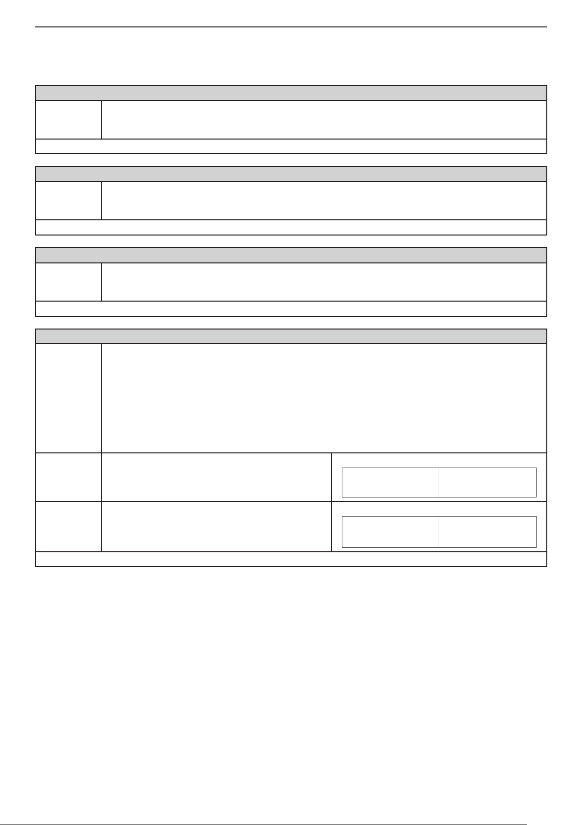
46 Installation and Programming Manual - СА62 Alarm Control Panel
6.2 Remote programming
The parameters for up / download programming of the integrated digital communicator and the VD60 voice dialer are
set on ADDRESSES 69хх.
ADDRESS 6901 - PERSONAL COMPUTER IDENTIFICATION NUMBER FOR UP / DOWN LOADING
The PC ID number for up / down loading is congured at this address.
PC ID
Default settings - 1234
ADDRESS 6902 - CONTROL PANEL IDENTIFICATION NUMBER
Panel ID
Default settings - 1234
ADDRESS 6904 - NUMBER OF RINGS
Number of
rings
Default settings - 4
Four digits can be introduced. Valid are symbols 0 to 9.
The entered number is saved with pressing the ENT button.
The control panel up/down loading ID number is entered at this address.
Four digits can be introduced. Valid are symbols 0 to 9.
The entered number is saved with pressing the ENT button.
The symbols 0 to 9 are used.
RINGS Up/ down loading is disabled if 0 is entered.
ATTENTION: It is recommended this parameter does not exceed the value of 7!
ADDRESS 6905 - ANSWERING MACHINE FUNCTION
This address enables the Answering Machine function for up / down loading. Every push of the digital
button alternatively changes enabled to disabled status.
Priority should be given to any automatic answering devices (like FAX or telephone answering ma-
Answering
machine
NO The "Answering machine" function is disabled.
YES The "Answering machine" function is enabled.
Default settings - NO
chines), if such are connected to the telephone line.
The Answering Machine function should be enabled in such cases. During initial income of a series of
calls (rings), the CA62 temporizes the maximum number of calls, set at Address 6904. The automatic
answering machine must be adjusted to a fewer number of rings. If within four minutes there is another
series of incoming calls the CA62 shall answer the rst one.
The display indication is shown in the tables below.
Indication
LED
Indication
LED
LCD
1 2 3 4 5 6
LCD
(1) (2) (3) (4) (5) (6)
Page 47
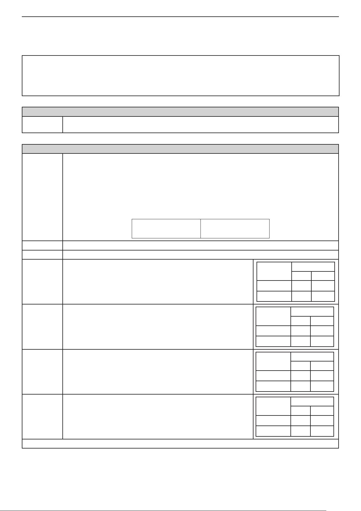
Installation and Programming Manual - СА62 Alarm Control Panel 47
7. PROGRAMMING OF PERIPHERAL DEVICES
7.1 Programming of Keyboards
At ADDRESSES 70хх are programmed the parameters and the attributes for the connected to the system keyboards.
Up to 4 keyboards can be connected in the system.
ATTENTION:
The keyboards models LED61, LCD62 and LCD62B DO NOT SUPPORT SIMULTANEOUSLY OPERATION WITH
THE BOTH PARTITIONS A and B.
Simultaneously operation with A and В partitions are supported from LED62, LED63VG SE, LCD63SE, LCD64
keyboards.
ADDRESS 7000 - CHECKING THE SET KEYBOARD ADDRESS
Keyboard
address
ADDRESS 7010 - KEYBOARD 1 SETTINGS
Keyboard 1
Settings
At this address the set with jumpers address of each keyboard can be checked.
The indication is hexadecimal.
At this address the Keyboard 1 parameters are assigned.
The digital buttons 1 to 6 are used for programming. Pressing them each time will alternatively change
the status of the parameter - active / inactive. At the end of the procedure only those parameters, which
correspond to the desired settings, should remain activated on the display.
Note: If a keyboard is attached to neither of the partitions, it can not control the system - arming,
disarming, bypass and etc. The user can only enter the engineer menu and do some settings in the
system.
At the default settings the display will show:
LED
LCD
(1) 2 3 4 5 (6)
1. PART A The keyboard is attached to Partition А. The User can perform actions in Partition A*.
2. PART B The keyboard is attached to Partition В. The User can perform actions in Partition B**.
Attribute
3. Chime
disable
4. Keypad
zone
5. Silent
Panic
6. Zone
Enable
This is local setting for the keyboard. When the attribute is assigned
the keyboard will not produce the "Chime" sound signal.
With this attribute is assigning the number of the keyboard zone - 1 or
7. With set parameter the keyboard will be zone 7. See also the table
on the right.
With this attribute is assigned, in case of sent PANIC alarm signal from
the keyboard, the siren will not sound.
With this attribute the engineer can disable or enable the keyboard
zone.
OFF
ON
Keypad
zone
ZONE 1
ZONE 7
Attribute
Disabled
Enabled
Attribute
Disabled
Enabled
Indication
LED LCD
Indication
LED LCD
Indication
LED LCD
Indication
LED LCD
3
(3)
4
(4)
5
(5)
6
(6)
Default settings - PART A, Zone Enable
* User with a personal code with rights to operate in Partition A. User code with rights to operate only with Partition B will
be rejected.
** User with a personal code with rights to operate in Partition B. User code with rights to operate only with Partition A will
be rejected.
Page 48

48 Installation and Programming Manual - СА62 Alarm Control Panel
ADDRESS 7011 - LEFT ARROW BUTTON OF KEYBOARD 1
At this address the arming mode of the system with the "left arrow" button of the keyboard 1 is as-
"Left arrow"
button of
Keyboard1
1. Full Arm
PART A
2. Stay Arm
PART A
3. Stay Arm
Part В
4. Inst Arm
Part А
5. Inst Arm
Part B
6. Arm
Following
Default settings - Arm Following
signed.
The digital buttons 1 to 6 are used for programming. Pressing them each time will alternatively change
the status of the parameter - active / inactive.
Only one attribute can be assigned.
Full arming mode for PARTITION А.
Stay arming mode for PARTITION А - the user is allowed to stay in certain zones in PARTITION A.
Stay arming mode for PARTITION B - the user is allowed to stay in certain zones in PARTITION B.
Instant arming mode of PARTITION А.
Instant arming mode of PARTITION B.
The arming of the partition(s) is with specifying the arming mode type: Full, Stay or Instant.
Example:
With assigning this parameter, the system arming will be as follows:
◄ (left arrow) + 0 - Full Arming Mode
◄ (left arrow) + 1 - Stay Arming Mode
◄ (left arrow) + 2 - Instant Arming Mode
ADDRESS 7012 - RIGHT ARROW BUTTON OF KEYBOARD 1
At this address the arming mode of the system with the "right arrow" button of the keyboard 1 is as-
"Right arrow"
button of
Keyboard1
1. Full Arm
PART В
2. Stay Arm
PART A
3. Stay Arm
Part В
4. Inst Arm
Part А
5. Inst Arm
Part B
6. Arm
Following
Default settings - Arm Following
signed.
The digital buttons 1 to 6 are used for programming. Pressing them each time will alternatively change
the status of the parameter - active / inactive.
Only one attribute can be assigned.
Full arming mode for PARTITION В.
Stay arming mode for PARTITION А - the user is allowed to stay in certain zones in PARTITION A.
Stay arming mode for PARTITION B - the user is allowed to stay in certain zones in PARTITION B.
Instant arming mode of PARTITION А.
Instant arming mode of PARTITION B.
The arming of the partition(s) is with specifying the arming mode type: Full, Stay or Instant.
Example:
With assigning this parameter, the system arming will be as follows:
► (right arrow) + 0 - Full Arming Mode
► (right arrow) + 1 - Stay Arming Mode
► (right arrow) + 2 - Instant Arming Mode
ADDRESS 7013 - ARM BUTTON FOR KEYBOARD 1
At this address the function of "ARM" button of the keyboard 1 is assigned.
ARM Button
Keyboard 1
1. No ARM The ARM button is disabled for arming the system.
2. Full
ARM All
Note: In the LED62 the button
The digital buttons 1, 2 and 6 are used for programming. Pressing them each time will alternatively
change the status of the parameter - active / inactive.
Only one attribute can be assigned.
The ARM button is enabled for Full arming of the partition(s) to which the keyboard is attached. DISARMING the both Partitions with one button (ARM) will function only, when at ADDRESS 7010 both
attributes 1. PART A and 2. PART B are assigned.
corresponds to ARM button.
Page 49

Installation and Programming Manual - СА62 Alarm Control Panel 49
The arming of the partition(s) is with specifying the arming mode type: Full, Stay or Instant.
Example:
6. Arm *
Following
Default settings - Arm Following
ADDRESSES 7020 ... 7023 – KEYBOARD 2 PROGRAMMING
The programming is the same as at ADDRESSES 7010 - 7013, as the programming is for Keyboard 2.
Default settings: Conguration - PARTITION А, Zone Enable; Left arrow - ARM Following; Right arrow - ARM
Following; ARM button - ARM Following
ADDRESSES 7030 ... 7033 – KEYBOARD 3 PROGRAMMING
The programming is the same as at ADDRESSES 7010 - 7013, as the programming is for Keyboard 3.
Default settings: Conguration - PARTITION А, Zone Enable; Left arrow - ARM Following; Right arrow - ARM
Following; ARM button - ARM Following
ADDRESSES 7040 ... 7043 – KEYBOARD 4 PROGRAMMING
The programming is the same as at ADDRESSES 7010 - 7013, as the programming is for Keyboard 4.
Default settings: Conguration - PARTITION А, Zone Enable; Left arrow - ARM Following; Right arrow - ARM
Following; ARM button - ARM Following
With assigning this parameter, the system arming will be as follows:
ARM or + 0 - Full Arming Mode
ARM or + 1 - Stay Arming Mode
ARM or + 2 - Instant Arming Mode
* NOTE: The Arm Following procedure is applied to user codes attached only to one of the Partitions.
7.2 Programming of Proxi Readers
At ADDRESSES 71хх are programmed the parameters and the attributes for the connected to the system proximity
card readers. Up to 2 readers can be connected in the system.
ADDRESS 7100 - PROXI READER 1 SETTINGS
At this address the parameters of Proxi Reader 1 are assigned.
Pressing them each time will alternatively change the status of the parameter - active / inactive.
Note: Every Proxi Reader can be attached to the both partitions in the system. In this case, if a proxi
card with user rights for the both partitions in the system is approached to the reader - the both parti-
Proxi 1
Settings
1. PART A
2. PART B
Default settings - PART A
tions will be armed or disarmed according their current status. If the one partition is armed and the
other is disarmed, then approaching the same user card will disarm the armed partition. The next approaching of the user card will arm the both partitions again.
At the default settings the display will show:
LED
The Proxi Reader is attached to Partition А.
Note: When the Proxi Reader is attached to Partition A only, then with approaching a user card with the
respective rights, if the Partition A is disarmed - it arms, if the Partition A is armed - it disarms.
The Proxi Reader is attached to Partition В.
Note: When the Proxi Reader is attached to Partition B only, then with approaching a user card with
the respective rights, if the Partition A is disarmed - it arms, if the Partition B is armed - it disarms.
LCD
(1) 2 3 4 5 6
ADDRESS 7110 - PROXI READER 2 SETTINGS
The programming is the same as ADDRESS 7100, as the programming is for Proxi Reader 2.
Default settings: PART А
Page 50

50 SUPPLEMENTS - СА62 Alarm Control Panel
DEFAULT
CONFIG. 3
DEFAULT
CONFIG. 2
5, 6
1, 2, 3, 4,
5, 6
1, 2, 3, 4,
DEFAULT
DEFAULT CONFIGURATION 0
CONFIG. 1
5, 6
1, 2, 3, 4,
6. TAMPER
ERROR
5. COMM
LINE
4. NO TEL
BLOWN
3. FUSE
30 min 30 min 30 min
ENGINEER PARAMETERS AND COMMON SETTINGS
0.
SUPPLEMENT A - Default programming tables
TABLE 1: Engineer Menu - DEFAULT CONFIGURATION 0, 1, 2 and 3
All parameters, attributes, codes and values in the
system are program in one and same way.
Follow the next sequence when program the system:
LED 1 LED 2 LED 3 LED 4 LED 5 LED 6
0000 Engineer code (7777) Digit 1 Digit 2 Digit 3 Digit 4 7777 7777 7777
ADDRESS MENU
two-digit number from 00 to 18, as every digit corresponds to 10 minutes interval. Defaut → 30 min.
A time delay indication for 220 V AC power supply failure in the range 0 - 180 min. The installer sets a
0001 Reset enable NO - LEDs off YES - LEDs on YES YES YES
0002 Default settings Press the keys from 1 to 6 consequently and conrm by ENTER
0011 Enable ambush code NO - LEDs off YES - LEDs on NO NO NO
0003 Partial reset Press the keys from 1 to 6 consequently and conrm by ENTER
0010 Quick ARM enable Part A Part B A and B A and B A and B
0012 Enable keypad block NO - LEDs off YES - LEDs on NO NO NO
0013 Trouble mask 1. AC LOST 2. BATT LOW
0014 AC delay NO (Instant indication) - LEDs off YES (Time delayed indication) - LEDs on NO NO NO
0015 Line fault delay Number 00 to 99 min → 00 min. 15 min 15 min 15 min
0016 Bell on Tel Line Fault Part A Part B
0017 Bell on TAMPER Silent TAMPER in DISARM - LEDs off Audible TAMPER in DISARM - LEDs on Audible Audible Audible
0018 AC Time delay entry
0020 Walk test ZONE 1 ZONE 2 ZONE 3 ZONE 4 ZONE 5 ZONE 6 ZONE 1- 6 ZONE 1- 6 ZONE 1- 6
0021 Keypad test Testing the keyboards indication.
0022 Outputs test PGM1 PGM2 PGM3 PGM4 PGM 1 - 4 PGM 1 - 4 PGM 1 - 4
0023 Comm. Display 1. Dial tone 2. Dialling 3. Wait HS 4. Send data 5. Wait kiss-off 6. All sent Steps 1- 6 Steps 1- 6 Steps 1- 6
0024 Display LOG Viewing the LOG memory.
0025 UDL / Direct UDL 1. Ring 2. Call back 3. Currier 4. Receive 5. Transmit 6. End Steps 1- 6 Steps 1- 6 Steps 1- 6
0026 Comm. HW test 1. Relay 2. Dial tone 3. Low freq. 4. High freq. 5. DTMF “3” Steps 1- 5 Steps 1- 5 Steps 1- 5
0030 Set clock Clock setting (HH:MM). Default at RESET → 00:00.
0031 Set date Date setting (DD.MM). Default at RESET → 01.01.
0040 Chime Enable/ Disable NO - LEDs off YES - LEDs on NO NO NO
0099 Software revision The Engineer can review the number of current software revision of the CA62 control panel at this address.
Page 51

SUPPLEMENTS - СА62 Alarm Control Panel 51
1. USER AND MANAGER CODES PROGRAMMING
1000 Default congurations Enter the number of the desired default conguration from 0 to 3. Setting at RESET → 0.
1001 Code digits 4 digits - LEDs off 6 digits - LEDs on 4 digits 4 digits 4 digits
1010 User code 1 (- - - -) DISARM STAY ARM BYPASS PROGRAM Part A Part B (1111), А (1111), А (1111), А
1020 User code 2 (- - - -) DISARM STAY ARM BYPASS PROGRAM Part A Part B (- - - -), А (- - - -), А (- - - -), А
1030 User code 3 (- - - -) DISARM STAY ARM BYPASS PROGRAM Part A Part B (- - - -), А (- - - -), А (- - - -), А
1040 User code 4 (- - - -) DISARM STAY ARM BYPASS PROGRAM Part A Part B (- - - -), А (- - - -), А (- - - -), А
1050 User code 5 (- - - -) DISARM STAY ARM BYPASS PROGRAM Part A Part B (- - - -), А (- - - -), А (- - - -), А
1060 User code 6 (- - - -) DISARM STAY ARM BYPASS PROGRAM Part A Part B (- - - -), А (- - - -), А (- - - -), А
1070 User code 7 (- - - -) DISARM STAY ARM BYPASS PROGRAM Part A Part B (- - - -), А (- - - -), А (- - - -), А
1080 User code 8 (- - - -) DISARM STAY ARM BYPASS PROGRAM Part A Part B (- - - -), А (- - - -), А (- - - -), А
1090 User code 9 (- - - -) DISARM STAY ARM BYPASS PROGRAM Part A Part B (- - - -), А (- - - -), А (- - - -), А
1110 User code 11 (- - - -) DISARM STAY ARM BYPASS PROGRAM Part A Part B (- - - -), А (- - - -), В (- - - -), В
1100 User code 10 (- - - -) DISARM STAY ARM BYPASS PROGRAM Part A Part B (- - - -), А (- - - -), А (- - - -), А
1120 User code 12 (- - - -) DISARM STAY ARM BYPASS PROGRAM Part A Part B (- - - -), А (- - - -), B (- - - -), В
1130 User code 13 (- - - -) DISARM STAY ARM BYPASS PROGRAM Part A Part B (- - - -), А (- - - -), B (- - - -), B
1140 User code 14 (- - - -) DISARM STAY ARM BYPASS PROGRAM Part A Part B (- - - -), А (- - - -), B (- - - -), B
1150 User code 15 (- - - -) DISARM STAY ARM BYPASS PROGRAM Part A Part B (- - - -), А (- - - -), B (- - - -), B
1160 User code 16 (- - - -) DISARM STAY ARM BYPASS PROGRAM Part A Part B (- - - -), А (- - - -), B (- - - -), B
1170 User code 17 (- - - -) DISARM STAY ARM BYPASS PROGRAM Part A Part B (- - - -), А (- - - -), B (- - - -), B
1180 User code 18 (- - - -) DISARM STAY ARM BYPASS PROGRAM Part A Part B (- - - -), А (- - - -), B (- - - -), B
1190 User code 19 (- - - -) DISARM STAY ARM BYPASS PROGRAM Part 1 Part B (- - - -), А (- - - -), B (- - - -), B
1200 User code 20 (- - - -) DISARM STAY ARM BYPASS PROGRAM Part A Part B (- - - -), А (- - - -), B (- - - -), B
1210 Chief Manager (0000) Part A Part B (0000); А, В (0000); А, В (0000); А, В
- Default settings at hardware or software RESET. The default CONFIGURATION 0 is set by default.
1220 Manager 1 (- - - -) Part A Part B (- - - -) (- - - -), А (- - - -), А
1230 Manager 2 (- - - -) Part A Part B (- - - -) (- - - -), В (- - - -), В
1240 Manager 3 (- - - -) Part A Part B (- - - -) (- - - -) (- - - -)
(- - - -) means, that there is no default programmed code for this user
TABLE 1 continues
Page 52

52 SUPPLEMENTS - СА62 Alarm Control Panel
DEFAULT
CONFIG. 3
DEFAULT
CONFIG. 2
DEFAULT
CONFIG. 1
Exit
1. Entry-
Exit
1. Entry-
Exit
1. Entry-
00. 24h
Burglary
00. 24h
Burglary
00. 24h
Burglary
В
Part A and
3. INSTANT
Exit
1. Entry-
DEFAULT CONFIGURATION 0
LED 1 LED 2 LED 3 LED 4 LED 5 LED 6
PROGRAMMING OF ZONES
2.
7. MEDICAL \ 8. KEY-SWITCH \ 9. AUXILIARY
0. UNUSED \ 1. Entry-Exit \ 2. FOLLOW \ 3. INSTANT \ 4. FIRE \ 5. PANIC \ 6. TAMPER \
09. Low Bottled gas level \ 10. High temperature \ 11. Low temperature
05. GSM Link Trouble \ 06. Refrigeration \ 07. Loss of heat \ 08. Foil Break \
00. 24h Burglary \ 01. Battery Low \ 02. Gas detector \ 03. Water Leakage \ 04. AC Lost\
ADDRESS MENU
2000 AutoBypass counter Enter a number from 0 to 9. Setting at RESET → 6 6 6 6
2001 Enable Instant NO - LEDs off YES - LEDs on NO NO NO
2011 ZONE 1 ATTRIBUTES 1 1. AUTOBYPASS 2. BYPASS 3. STAY 4. FORCE 5. DOUBLE 6. E/E FINAL 2. BYPASS 2. BYPASS 2. BYPASS
2010 Zone 1 type
2012 ZONE 1 ATTRIBUTES 2 1. Bell delay 2. Silent 3. VideoOnArmed 4. Write to LOG 5. Chime
2013 ZONE 1 ATTRIBUTES 3 1. Pulse / Latch 2. Full / Stay 3. Disarm Enable 3.Disarm En. 3.Disarm En. 3.Disarm En.
2014 ZONE 1 ATTRIBUTES AUX
2015 ZONE 1 Attachment Part A Part B Part A Part A
2020 Zone 2 type Choose the type of ZONE 2 (0 - 9). Setting at RESET → 0. UNUSED 2. FOLLOW 2. FOLLOW 2. FOLLOW
2021 ZONE 2 ATTRIBUTES 1 1. AUTOBYPASS 2. BYPASS 3. STAY 4. FORCE 5. DOUBLE 6. E/E FINAL 2 and 3 2 and 3 2 and 3
2022 ZONE 2 ATTRIBUTES 2 1. Bell delay 2. Silent 3. VideoOnArmed 4. Write to LOG 5. Chime
2023 ZONE 2 ATTRIBUTES 3 1. Pulse / Latch 2. Full / Stay 3. Disarm Enable 3.Disarm En. 3.Disarm En. 3.Disarm En.
2024 ZONE 2 ATTRIBUTES AUX Choose the Attribute AUX for ZONE 2 (00 - 11).Setting at RESET → 00. 24h Burglary 00 00 00
2025 ZONE 2 Attachment Part A Part B Part A Part A Part A and В
2026 ZONE 2 Hardware 1. EOL 2. Fast/ Regular 3.Power-up Delay 4.DOUBLING
2030 Zone 3 type Choose the type of ZONE 3 (0 - 9). Setting at RESET → 0. UNUSED 3. INSTANT 3. INSTANT 3. INSTANT
2031 ZONE 3 ATTRIBUTES 1 1. AUTOBYPASS 2. BYPASS 3. STAY 4. FORCE 5. DOUBLE 6. E/E FINAL 2 and 3 2 and 3 2 and 3
2032 ZONE 3 ATTRIBUTES 2 1. Bell delay 2. Silent 3. VideoOnArmed 4. Write to LOG 5. Chime
2033 ZONE 3 ATTRIBUTES 3 1. Pulse / Latch 2. Full / Stay 3. Disarm Enable 3.Disarm En. 3.Disarm En. 3.Disarm En.
2034 ZONE 3 ATTRIBUTES AUX Choose the Attribute AUX for ZONE 3 (00 - 11).Setting at RESET → 00. 24h Burglary 00 00 00
2035 ZONE 3 Attachment Part A Part B Part A Part A Part A
2036 ZONE 3 Hardware 1. EOL 2. Fast/ Regular 3.Power-up Delay 4.DOUBLING
2040 Zone 4 type Choose the type of ZONE 4 (0 - 9). Setting at RESET → 0. UNUSED 3. INSTANT
2041 ZONE 4 ATTRIBUTES 1 1. AUTOBYPASS 2. BYPASS 3. STAY 4. FORCE 5. DOUBLE 6. E/E FINAL 2 and 3 2 and 3 2 and 3
2042 ZONE 4 ATTRIBUTES 2 1. Bell delay 2. Silent 3. VideoOnArmed 4. Write to LOG 5. Chime
2043 ZONE 4 ATTRIBUTES 3 1. Pulse / Latch 2. Full / Stay 3. Disarm Enable 3.Disarm En. 3.Disarm En. 3.Disarm En.
2044 ZONE 4 ATTRIBUTES AUX Choose the Attribute AUX for ZONE 4 (00 - 11).Setting at RESET → 00. 24h Burglary 00 00 00
2045 ZONE 4 Attachment Part A Part B Part A Part В Part A
2046 ZONE 4 Hardware 1. EOL 2. Fast/ Regular 3.Power-up Delay 4.DOUBLING
2047 Zone 4 counter Enter a number from 0 to 9. Setting at RESET → 0 0 0 0
TABLE 1 continues
Page 53

SUPPLEMENTS - СА62 Alarm Control Panel 53
2050 Zone 5 type Choose the type of ZONE 5 (0 - 9). Setting at RESET → 0. UNUSED 5. PANIC 2. FOLLOW 3. INSTANT
2051 ZONE 5 ATTRIBUTES 1 1. AUTOBYPASS 2. BYPASS 3. STAY 4. FORCE 5. DOUBLE 6. E/E FINAL 2 2 and 3 2
2052 ZONE 5 ATTRIBUTES 2 1. Bell delay 2. Silent 3. VideoOnArmed 4. Write to LOG 5. Chime
2053 ZONE 5 ATTRIBUTES 3 1. Pulse / Latch 2. Full / Stay 3. Disarm Enable 3.Disarm En. 3.Disarm En. 3.Disarm En.
2054 ZONE 5 ATTRIBUTES AUX Choose the Attribute AUX for ZONE 5 (00 - 11).Setting at RESET → 00. 24h Burglary 00 00 00
2055 ZONE 5 Attachment Part A Part B Part A Part В Part B
2056 ZONE 5 Hardware 1. EOL 2. Fast/ Regular 3.Power-up Delay 4.DOUBLING
2060 Zone 6 type Choose the type of ZONE 6 (0 - 9). Setting at RESET → 0. UNUSED 6. TAMPER 3. INSTANT 3. INSTANT
2061 ZONE 6 ATTRIBUTES 1 1. AUTOBYPASS 2. BYPASS 3. STAY 4. FORCE 5. DOUBLE 6. E/E FINAL 2 and 3 2
2062 ZONE 6 ATTRIBUTES 2 1. Bell delay 2. Silent 3. VideoOnArmed 4. Write to LOG 5. Chime
2063 ZONE 6 ATTRIBUTES 3 1. Pulse / Latch 2. Full / Stay 3. Disarm Enable 3.Disarm En. 3.Disarm En. 3.Disarm En.
2064 ZONE 6 ATTRIBUTES AUX Choose the Attribute AUX for ZONE 6 (00 - 11).Setting at RESET → 00. 24h Burglary 00 00 00
2065 ZONE 6 Attachment Part A Part B Part A Part В Part B
2066 ZONE 6 Hardware 1. EOL 2. Fast/ Regular 3.Power-up Delay 4.DOUBLING
2070 Zone 7 type Choose the type of ZONE 7 (0 - 9). Setting at RESET → 0. UNUSED 0. UNUSED 0. UNUSED 0. UNUSED
2071 ZONE 7 ATTRIBUTES 1 1. AUTOBYPASS 2. BYPASS 3. STAY 4. FORCE 5. DOUBLE 6. E/E FINAL 2 2 2
2072 ZONE 7 ATTRIBUTES 2 1. Bell delay 2. Silent 3. VideoOnArmed 4. Write to LOG 5. Chime
2073 ZONE 7 ATTRIBUTES 3 1. Pulse / Latch 2. Full / Stay 3. Disarm Enable 3.Disarm En. 3.Disarm En. 3.Disarm En.
2074 ZONE 7 ATTRIBUTES AUX Choose the Attribute AUX for ZONE 7 (00 - 11).Setting at RESET → 00. 24h Burglary 00 00 00
2075 ZONE 7 Attachment Part A Part B Part A Part A Part A
2080 Zone 8 type Choose the type of ZONE 8 (0 - 9). Setting at RESET → 0. UNUSED 0. UNUSED 0. UNUSED 0. UNUSED
2081 ZONE 8 ATTRIBUTES 1 1. AUTOBYPASS 2. BYPASS 3. STAY 4. FORCE 5. DOUBLE 6. E/E FINAL 2 2 2
2082 ZONE 8 ATTRIBUTES 2 1. Bell delay 2. Silent 3. VideoOnArmed 4. Write to LOG 5. Chime
2083 ZONE 8 ATTRIBUTES 3 1. Pulse / Latch 2. Full / Stay 3. Disarm Enable 3.Disarm En. 3.Disarm En. 3.Disarm En.
2084 ZONE 8 ATTRIBUTES AUX Choose the Attribute AUX for ZONE 8 (00 - 11).Setting at RESET → 00. 24h Burglary 00 00 00
2085 ZONE 8 Attachment Part A Part B Part A Part A Part A
2090 Zone 9 type Choose the type of ZONE 9 (0 - 9). Setting at RESET → 0. UNUSED 0. UNUSED 0. UNUSED 0. UNUSED
2091 ZONE 9 ATTRIBUTES 1 1. AUTOBYPASS 2. BYPASS 3. STAY 4. FORCE 5. DOUBLE 6. E/E FINAL 2 2 2
2092 ZONE 9 ATTRIBUTES 2 1. Bell delay 2. Silent 3. VideoOnArmed 4. Write to LOG 5. Chime
2093 ZONE 9 ATTRIBUTES 3 1. Pulse / Latch 2. Full / Stay 3. Disarm Enable 3.Disarm En. 3.Disarm En. 3.Disarm En.
2094 ZONE 9 ATTRIBUTES AUX Choose the Attribute AUX for ZONE 9 (00 - 11).Setting at RESET → 00. 24h Burglary 00 00 00
2095 ZONE 9 Attachment Part A Part B Part A Part A Part A
2100 Zone 10 type Choose the type of ZONE 10 (0 - 9). Setting at RESET → 0. UNUSED 0. UNUSED 0. UNUSED 0. UNUSED
TABLE 1 continues
2101 ZONE10 ATTRIBUTES 1 1. AUTOBYPASS 2. BYPASS 3. STAY 4. FORCE 5. DOUBLE 6. E/E FINAL 2 2 2
2102 ZONE10 ATTRIBUTES 2 1. Bell delay 2. Silent 3. VideoOnArmed 4. Write to LOG 5. Chime
2103 ZONE 10 ATTRIBUTES 3 1. Pulse / Latch 2. Full / Stay 3. Disarm Enable 3.Disarm En. 3.Disarm En. 3.Disarm En.
2104 ZONE 10 ATTRIBUTES AUX Choose the Attribute AUX for ZONE 10 (00 - 11).Setting at RESET → 00. 24h Burglary 00 00 00
2105 ZONE 10 Attachment Part A Part B Part A Part A Part A
Page 54
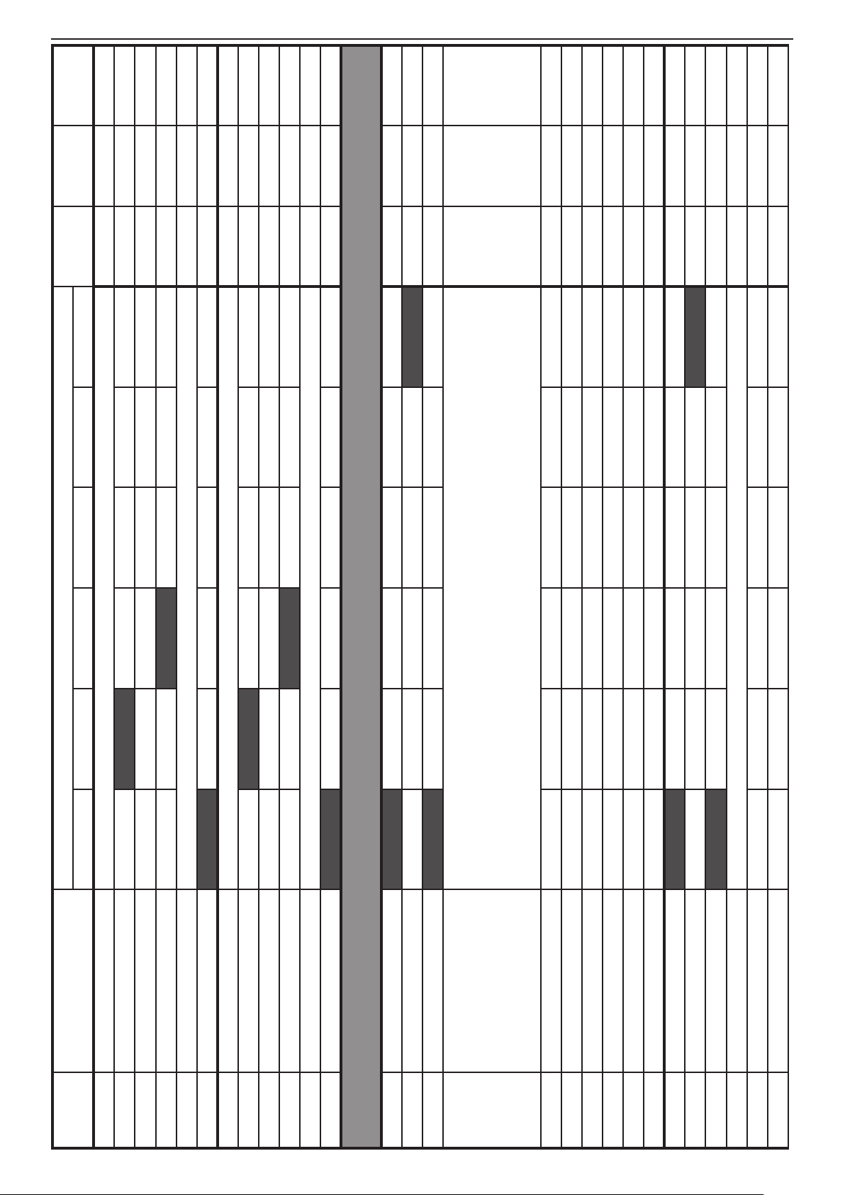
54 SUPPLEMENTS - СА62 Alarm Control Panel
DEFAULT
CONFIG. 3
DEFAULT
CONFIG. 2
DEFAULT
CONFIG. 1
00 00 00
DEFAULT CONFIGURATION 0
LED 1 LED 2 LED 3 LED 4 LED 5 LED 6
PGM AND SIREN OUTPUTS PROGRAMMING
3.
12. Battery Trouble \ 13. Wireless Transmitter Supervision Loss \
Panic Alarm \ 09. AMBUHS Code \ 10. Chime \ 11. Auxiliary Alarm \
14. Wireless Transmitter Battery Low \ 15. Auto-ARM \ 16. Vide-On-Armed \
00. No Extension \ 01. Battery Trouble \ 02. Blown Fuse \ 03. Tel. Line Trouble \
04. AC Loss - Main board \ 05. AC Loss - Zone \ 06. Keypad Alarm \ 07. Keypad Fire Alarm\ 08. Keypad
17. Zone Violation \ 18. Code Used Signalling \ 19. Proximity Card Used Signalling
ADDRESS MENU
2111 ZONE 11 ATTRIBUTES 1 1. AUTOBYPASS 2. BYPASS 3. STAY 4. FORCE 5. DOUBLE 6. E/E FINAL 2 2 2
2110 Zone 11 type Choose the type of ZONE 11 (0 - 9). Setting at RESET → 0. UNUSED 0. UNUSED 0. UNUSED 0. UNUSED
2112 ZONE 11 ATTRIBUTES 2 1. Bell delay 2. Silent 3. VideoOnArmed 4. Write to LOG 5. Chime
2113 ZONE 11 ATTRIBUTES 3 1. Pulse / Latch 2. Full / Stay 3. Disarm Enable 3.Disarm En. 3.Disarm En. 3.Disarm En.
2114 ZONE 11 ATTRIBUTES AUX Choose the Attribute AUX for ZONE 11 (00 - 11).Setting at RESET → 00. 24h Burglary 00 00 00
2115 ZONE 11 Attachment Part A Part B Part A Part A Part A
2120 Zone 12 type Choose the type of ZONE 12 (0 - 9). Setting at RESET → 0. UNUSED 0. UNUSED 0. UNUSED 0. UNUSED
2122 ZONE 12 ATTRIBUTES 2 1. Bell delay 2. Silent 3. VideoOnArmed 4. Write to LOG 5. Chime
2121 ZONE 12 ATTRIBUTES 1 1. AUTOBYPASS 2. BYPASS 3. STAY 4. FORCE 5. DOUBLE 6. E/E FINAL 2 2 2
2123 ZONE 12 ATTRIBUTES 3 1. Pulse / Latch 2. Full / Stay 3. Disarm Enable 3.Disarm En. 3.Disarm En. 3.Disarm En.
2124 ZONE 12 ATTRIBUTES AUX Choose the Attribute AUX for ZONE 12 (00 - 11).Setting at RESET → 00. 24h Burglary 00 00 00
2125 ZONE 12 Attachment Part A Part B Part A Part A Part A
3011 PGM 1 Parameters 2 1. MEDICAL 2. PS/BYPASS 3. SIREN 4. TECH.TRBL 5. PULSE/LATCH 6. POLARITY 6 6 6
3010 PGM 1 Parameters 1 1. ALARM 2. PANIC 3. TAMPER 4. FIRE 5. FIRE RESET 6. ON / OFF 6 6 6
3012 PGM 1 Attachment Part A Part B Part A Part A Part A
3013 PGM 1 Extension
3014 PGM 1 Extension Х1 Code/ Zone 1 Code/ Zone 2 Code/ Zone 3 Code/ Zone 4 Code/ Zone 5 Code/ Zone 6
3015 PGM 1 Extension Х2 Code/ Zone 7 Code/ Zone 8 Code/ Zone 9 Code/ Zone 10 Code/ Zone 11 Code/ Zone 12
3016 PGM 1 Extension Х3 Code 13 Code 14 Code 15 Code 16 Code 17 Code 18
3017 PGM 1 Extension Х4 Code 19 Code 20 Manager Manager 1 Manager 2 Manager 3
3018 PGM 1 Device ID Keyboard 1 Keyboard 2 Keyboard 3 Keyboard 4
3019 PGM 1 Device ID Proxi Reader 1 Proxi Reader 2
3020 PGM 2 Parameters 1 1. ALARM 2. PANIC 3. TAMPER 4. FIRE 5. FIRE RESET 6. ON / OFF 1, 3 1, 3 1, 3
3021 PGM 2 Parameters 2 1. MEDICAL 2. PS/BYPASS 3. SIREN 4. TECH.TRBL 5. PULSE/LATCH 6. POLARITY 6 6 6
3022 PGM 2 Attachment Part A Part B Part A Part A Part A
3023 PGM 2 Extension Choose an Extension number for PGM 2 (00 - 19). Setting at RESET → 00. No Extension 00 00 00
3024 PGM 2 Extension Х1 Code/ Zone 1 Code/ Zone 2 Code/ Zone 3 Code/ Zone 4 Code/ Zone 5 Code/ Zone 6
3025 PGM 2 Extension Х2 Code/ Zone 7 Code/ Zone 8 Code/ Zone 9 Code/ Zone 10 Code/ Zone 11 Code/ Zone 12
TABLE 1 continues
Page 55

SUPPLEMENTS - СА62 Alarm Control Panel 55
9999 9999 9999
Valid Code Valid Code Valid Code
4. PARTITIONS PROGRAMMING
LEDs on
Bell Time at ADDRESS 4012 -
Settings at RESET → FFFF.
LEDs off
Until a valid user code -
Communication account for Part A - 4 digits (from 0 to 9 + symbols А to F).
3026 PGM 2 Extension Х3 Code 13 Code 14 Code 15 Code 16 Code 17 Code 18
3027 PGM 2 Extension Х4 Code 19 Code 20 Manager Manager 1 Manager 2 Manager 3
3028 PGM 2 Device ID Keyboard 1 Keyboard 2 Keyboard 3 Keyboard 4
3029 PGM 2 Device ID Proxi Reader 1 Proxi Reader 2
3030 PGM 3 Parameters 1 1. ALARM 2. PANIC 3. TAMPER 4. FIRE 5. FIRE RESET 6. ON / OFF
3031 PGM 3 Parameters 2 1. MEDICAL 2. PS/BYPASS 3. SIREN 4. TECH.TRBL 5. PULSE/LATCH 6. POLARITY 4, 6 4, 6 4, 6
3032 PGM 3 Attachment Part A Part B Part A Part A Part A
3033 PGM 3 Extension Choose an Extension number for PGM 3 (00 - 19). Setting at RESET → 00. No Extension 00 00 00
3034 PGM 3 Extension Х1 Code/ Zone 1 Code/ Zone 2 Code/ Zone 3 Code/ Zone 4 Code/ Zone 5 Code/ Zone 6
3035 PGM 3 Extension Х2 Code/ Zone 7 Code/ Zone 8 Code/ Zone 9 Code/ Zone 10 Code/ Zone 11 Code/ Zone 12
3036 PGM 3 Extension Х3 Code 13 Code 14 Code 15 Code 16 Code 17 Code 18
3037 PGM 3 Extension Х4 Code 19 Code 20 Manager Manager 1 Manager 2 Manager 3
3038 PGM 3 Device ID Keyboard 1 Keyboard 2 Keyboard 3 Keyboard 4
3039 PGM 3 Device ID Proxi Reader 1 Proxi Reader 2
3040 SIREN (PGM4) Parameters 1 1. ALARM 2. PANIC 3. TAMPER 4. FIRE 5. FIRE RESET 6. ON / OFF
3041 SIREN (PGM4) Parameters 2 1. MEDICAL 2. PS/BYPASS 3. SIREN 4. TECH.TRBL 5. PULSE/LATCH 6. POLARITY 3, 6 3, 6 3, 6
3042 SIREN (PGM4) Attachment Part A Part B Part A
3043 SIREN (PGM4) Extension Choose an Extension number for PGM 4 (00 - 19). Setting at RESET → 00. No Extension 00 00 00
3044 SIREN (PGM4) Extension Х1 Code/ Zone 1 Code/ Zone 2 Code/ Zone 3 Code/ Zone 4 Code/ Zone 5 Code/ Zone 6
3045 SIREN (PGM4) Extension Х2 Code/ Zone 7 Code/ Zone 8 Code/ Zone 9 Code/ Zone 10 Code/ Zone 11 Code/ Zone 12
3046 SIREN (PGM4) Extension Х3 Code 13 Code 14 Code 15 Code 16 Code 17 Code 18
3047 SIREN (PGM4) Extension Х4 Code 19 Code 20 Manager Manager 1 Manager 2 Manager 3
3048 SIREN (PGM4) Device ID Keyboard 1 Keyboard 2 Keyboard 3 Keyboard 4
3049 SIREN (PGM4) Device ID Proxi Reader 1 Proxi Reader 2
FIRE Duration Part A
4011 Entry time Part A Enter Entry time for Part A (0-99 sec). Settings at RESET → 15. 15 15 15
4010 Exit time Part A Enter Exit time for Part A (0-99 sec). Settings at RESET → 45. 45 45 45
4012 Bell time Part A 0-99 min. Settings at → 3. 3 3 3
4013 Bell delay Part A 0-99 min. Settings at → 0. 0 0 0
4014 Auto ARM time Part A Enter time (HH:MM) for Automatic ARM of Part A. Settings at RESET → 00:00. 00:00 00:00 00:00
4015
TABLE 1 continues
Communication account
Part A
4016 ATTRIBUTES Part A 1. Sqwk ARM 2. Sqwk DISARM 3. Auto-Arm Enbl 4. Arm Full / Stay
4017
Page 56

56 SUPPLEMENTS - СА62 Alarm Control Panel
DEFAULT
CONFIG. 3
DEFAULT
CONFIG. 2
DEFAULT
CONFIG. 1
Valid Code Valid Code Valid Code
LEDs on
9999 9999 9999
no tel.
number
no tel.
number
no tel.
number
no tel.
number
no tel.
number
no tel.
number
no tel.
number
no tel.
number
no tel.
number
no tel.
number
no tel.
number
no tel.
number
no tel.
number
no tel.
number
no tel.
number
no tel.
number
no tel.
number
no tel.
number
DEFAULT CONFIGURATION 0
LED 1 LED 2 LED 3 LED 4 LED 5 LED 6
Bell Time at ADDRESS 4022 -
Settings at RESET → FFFF.
LEDs off
Until a valid user code -
Communication account for Part B - 4 digits (from 0 to 9 + symbols А to F).
6. PROGRAMMING OF COMMUNICATION DEVICES
number=ARM+5. Default settings at RESET -> no number.
Max. phone number length - 16 symbols, pulse dialing=ARM+0, DTMF dialing=ARM+1,
pause=ARM+2, Enabling "Dial tone detector"=ARM+3, Disabling "Dial tone detector" =ARM=4, clear
number=ARM+5. Default settings at RESET -> no number.
Max. phone number length - 16 symbols, pulse dialing=ARM+0, DTMF dialing=ARM+1,
pause=ARM+2, Enabling "Dial tone detector"=ARM+3, Disabling "Dial tone detector" =ARM=4, clear
number=ARM+5. Default settings at RESET -> no number.
Max. phone number length - 16 symbols, pulse dialing=ARM+0, DTMF dialing=ARM+1,
pause=ARM+2, Enabling "Dial tone detector"=ARM+3, Disabling "Dial tone detector" =ARM=4, clear
number=ARM+5. Default settings at RESET -> no number.
Max. phone number length - 16 symbols, pulse dialing=ARM+0, DTMF dialing=ARM+1,
pause=ARM+2, Enabling "Dial tone detector"=ARM+3, Disabling "Dial tone detector" =ARM=4, clear
number=ARM+5. Default settings at RESET -> no number.
Max. phone number length - 16 symbols, pulse dialing=ARM+0, DTMF dialing=ARM+1,
pause=ARM+2, Enabling "Dial tone detector"=ARM+3, Disabling "Dial tone detector" =ARM=4, clear
number=ARM+5. Default settings at RESET -> no number.
Max. phone number length - 16 symbols, pulse dialing=ARM+0, DTMF dialing=ARM+1,
pause=ARM+2, Enabling "Dial tone detector"=ARM+3, Disabling "Dial tone detector" =ARM=4, clear
ADDRESS MENU
4020 Exit time Part B Enter Exit time for Part B (0-99 sec). Settings at RESET → 45. 45 45 45
4021 Entry time Part B Enter Entry time for Part B (0-99 sec). Settings at RESET → 15. 15 15 15
FIRE Duration Part B
4022 Bell time Part B 0-99 min. Settings at RESET → 3. 3 3 3
4023 Bell delay Part B 0-99 min. Settings at RESET → 0. 0 0 0
4024 Auto ARM time Part B Enter time (HH:MM) for Automatic ARM of Part B. Settings at RESET → 00:00. 00:00 00:00 00:00
4025
Communication account
Part B
4026 ATTRIBUTES Part B 1. Sqwk ARM 2. Sqwk DISARM 3. Auto-Arm Enbl 4. Arm Full / Stay
4027
6001 Communication attempts From 0 to 9 attempts. Settings at RESET -> 0, meaning 4 attempts 0, 4 attempts 0, 4 attempts 0, 4 attempts
6002 Test period Enter the duration of the test period - from 00 to 99 hours. Settings at RESET → 24. 24 24 24
6003 Test start time Enter the time for starting test period (HH:ММ). Settings at RESET → 00:05. 00:05 00:05 00:05
6010 Telephone number 1
6011 Comm. Protocol 1 Enter communication protocol number (1 - Contact ID; 2-SIA). Settings at RESET → 2-SIA. 2 2 2
6012 Messages 1. ALARM 2. PANIC 3. FIRE 4. ON/OFF+BPS 5. MEDICAL 6. TROUBLE from 1 to 6 from 1 to 6 from 1 to 6
6020 Telephone number 2
6021 Comm. Protocol 2 Enter communication protocol number (1 - Contact ID; 2-SIA). Settings at RESET → 2-SIA. 2 2 2
6022 Messages 1. ALARM 2. PANIC 3. FIRE 4. ON/OFF+BPS 5. MEDICAL 6. TROUBLE
6030 VD60 Programming Records and Playback voice message into voice dialer VD60
Dialer VD60
Telephone number 1
Dialer VD60
Telephone number 2
6031
6032
Dialer VD60
Telephone number 3
Dialer VD60
Telephone number 4
6033
6034
TABLE 1 continues
Page 57

SUPPLEMENTS - СА62 Alarm Control Panel 57
1 1 1
NO NO NO
YES - LEDs ON
АС LOST, ВАТТ LOW
1 - Alarm, Panic, Tamper, Fire, Medical,
(Continuous message transmitting)
6 1 1
6. ARM
Following
Part B
5. Instant ARM
Part A
4. Instant ARM
Part B
3. Stay ARM
6 1 1
6. ARM
Following
Part B
5. Instant ARM
Part A
4. Instant ARM
Part B
3. Stay ARM
6 6 6
6. ARM
Following
6 6 6
6. ARM
Following
Part B
5. Instant ARM
Part A
4. Instant ARM
Part B
3. Stay ARM
6 1 6
6. ARM
Following
Part B
5. Instant ARM
Part A
4. Instant ARM
Part B
3. Stay ARM
6 6 6
6. ARM
Following
6 6 6
6. ARM
Following
Part B
5. Instant ARM
Part A
4. Instant ARM
Part B
3. Stay ARM
6 6 6
6. ARM
Following
Part B
5. Instant ARM
Part A
4. Instant ARM
Part B
3. Stay ARM
6 6 6
6. ARM
Following
Part B
5. Instant ARM
Part A
4. Instant ARM
Part B
3. Stay ARM
6 6 6
6. ARM
Following
Part B
5. Instant ARM
Part A
4. Instant ARM
Part B
3. Stay ARM
NO - LEDs OFF
(Message transmitting can be stopped)
6035 Events VD60 0 - Alarm/ TAMPER by zones
6036 Message Transmitting VD60
6901 PC ID number for UDL 4 Digits (from 0 to 9). Settings at RESET → 1234. 1234 1234 1234
6902 Panel ID number for UDL 4 Digits (from 0 to 9). Settings at RESET → 1234. 1234 1234 1234
7. PROGRAMMING OF PERIPHERAL DEVICES
Part A
Part A
2. Stay ARM
2. Stay ARM
Part A
Part B
1. Full ARM
1. Full ARM
6904 Number of rings Enter number of rings from 1 to 9. Settings at RESET -> 4. 4 4 4
6905 Answering machine NO - LEDs off YES - LEDs on NO NO NO
7000 Keyboard address Display on each keyboard its address as congured with its jumpers.
7011 Keyboard 1 left arrow
7010 Keyboard 1 Settings 1. Part A 2. Part B 3. Chime disable 4. Keypad zone 5. Silent panic 6. Zone enable 1, 6 1, 6 1, 2
7012 Keyboard 1 right arrow
7013 Keyboard 1 ARM Button 1. NO ARM 2. Full ARM all
Part A
Part A
2. Stay ARM
2. Stay ARM
Part A
Part B
1. Full ARM
1. Full ARM
7020 Keyboard 2 Settings 1. Part A 2. Part B 3. Chime disable 4. Keypad zone 5. Silent panic 6. Zone enable 1, 6 2 1, 6
7021 Keyboard 2 left arrow
7022 Keyboard 2 right arrow
7023 Keyboard 2 ARM Button 1. NO ARM 2. Full ARM all
7030 Keyboard 3 Settings 1. Part A 2. Part B 3. Chime disable 4. Keypad zone 5. Silent panic 6. Zone enable 1, 6 1,6 1, 6
Part A
Part A
2. Stay ARM
2. Stay ARM
Part A
Part B
1. Full ARM
1. Full ARM
7031 Keyboard 3 left arrow
7032 Keyboard 3 right arrow
7033 Keyboard 3 ARM Button 1. NO ARM 2. Full ARM all 6. ARM Following 6 6 6
7040 Keyboard 4 Settings 1. Part A 2. Part B 3. Chime disable 4. Keypad zone 5. Silent panic 6. Zone enable 1, 6 1,6 1, 6
Part A
Part A
2. Stay ARM
2. Stay ARM
Part A
Part B
1. Full ARM
1. Full ARM
7041 Keyboard 4 left arrow
7042 Keyboard 4 right arrow
7043 Keyboard 4 ARM Button 1. NO ARM 2. Full ARM all 6. ARM Following 6 6 6
7100 Proxi reader 1 Setting Part A Part B Part A Part A Part A
7110 Proxi reader 2 Setting Part A Part B Part A Part A Part A
TABLE 1 continues
Page 58

58 SUPPLEMENTS - СА62 Alarm Control Panel
DEFAULT
CONFIG. 3
DEFAULT
CONFIG. 2
DEFAULT
CONFIG. 1
DEFAULT CONFIGURATION 0
SUPPLEMENT A - Default Programming Tables
TABLE 2: Manager Menu - DEFAULT CONFIGURATION 0, 1, 2 and 3
The UDL communication will be restored at 00.00 h system time.
Enter number from 00 up to 99. Default settings at RESET - 10 attempts.
Enter permissible number of valid access codes (ARM / DISARM / BYPASS / PC ID) for UDL and 24 hour period.
With reaching the permissible number of valid access codes, the system will be blocked - there would be no UDL communication.
LED 1 LED 2 LED 3 LED 4 LED 5 LED 6
ADDRESS MENU
000 Remote Access 1. DISARMING 2. ARMING 3. Code Access 4. Programming 5. View LOG 6. Bypass 2, 4, 5 2, 4, 5 2, 4, 5
001 Engineer access DISABLED - LEDs off ENABLED - LEDs on ENABLED ENABLED ENABLED
002 Comm. manual test Sending of test messages to central monitoring station or test message with the voice dialer VD60.
009 UDL Access Block
011 User code 1 Attributes 1. DISARM 2. STAY ARM 3. BYPASS 4. PROGRAM 5. Part A 6. Part B from 1 to 5 from 1 to 5 from 1 to 5
010 User code 1 (- - - -) Enter 4 or 6 digit code (depends on the settings at ADDRESS 1001 from the Engineering Menu) 1111 1111 1111
012 Proximity card Register Put the card close to the proximity reader.
013 Proximity card Delete Press ENTER button to delete the card.
020 User code 2 (- - - -) Enter 4 or 6 digit code (depends on the settings at ADDRESS 1001 from the Engineering Menu) (- - - -) (- - - -) (- - - -)
021 User code 2 Attributes 1. DISARM 2. STAY ARM 3. BYPASS 4. PROGRAM 5. Part A 6. Part B from 1 to 5 from 1 to 5 from 1 to 5
022 Proximity card Register Put the card close to the proximity reader.
023 Proximity card Delete Press ENTER button to delete the card.
030 User code 3 (- - - -) Enter 4 or 6 digit code (depends on the settings at ADDRESS 1001 from the Engineering Menu) (- - - -) (- - - -) (- - - -)
031 User code 3 Attributes 1. DISARM 2. STAY ARM 3. BYPASS 4. PROGRAM 5. Part A 6. Part B from 1 to 5 from 1 to 5 from 1 to 5
032 Proximity card Register Put the card close to the proximity reader.
033 Proximity card Delete Press ENTER button to delete the card.
040 User code 4 (- - - -) Enter 4 or 6 digit code (depends on the settings at ADDRESS 1001 from the Engineering Menu) (- - - -) (- - - -) (- - - -)
041 User code 4 Attributes 1. DISARM 2. STAY ARM 3. BYPASS 4. PROGRAM 5. Part A 6. Part B from 1 to 5 from 1 to 5 from 1 to 5
042 Proximity card Register Put the card close to the proximity reader.
043 Proximity card Delete Press ENTER button to delete the card.
050 User code 5 (- - - -) Enter 4 or 6 digit code (depends on the settings at ADDRESS 1001 from the Engineering Menu) (- - - -) (- - - -) (- - - -)
051 User code 5 Attributes 1. DISARM 2. STAY ARM 3. BYPASS 4. PROGRAM 5. Part A 6. Part B from 1 to 5 from 1 to 5 from 1 to 5
052 Proximity card Register Put the card close to the proximity reader.
053 Proximity card Delete Press ENTER button to delete the card.
060 User code 6 (- - - -) Enter 4 or 6 digit code (depends on the settings at ADDRESS 1001 from the Engineering Menu) (- - - -) (- - - -) (- - - -)
061 User code 6 Attributes 1. DISARM 2. STAY ARM 3. BYPASS 4. PROGRAM 5. Part A 6. Part B from 1 to 5 from 1 to 5 from 1 to 5
062 Proximity card Register Put the card close to the proximity reader.
063 Proximity card Delete Press ENTER button to delete the card.
070 User code 7 (- - - -) Enter 4 or 6 digit code (depends on the settings at ADDRESS 1001 from the Engineering Menu) (- - - -) (- - - -) (- - - -)
071 User code 7 Attributes 1. DISARM 2. STAY ARM 3. BYPASS 4. PROGRAM 5. Part A 6. Part B from 1 to 5 from 1 to 5 from 1 to 5
Page 59

SUPPLEMENTS - СА62 Alarm Control Panel 59
072 Proximity card Register Put the card close to the proximity reader.
073 Proximity card Delete Press ENTER button to delete the card.
080 User code 8 (- - - -) Enter 4 or 6 digit code (depends on the settings at ADDRESS 1001 from the Engineering Menu) (- - - -) (- - - -) (- - - -)
081 User code 8 Attributes 1. DISARM 2. STAY ARM 3. BYPASS 4. PROGRAM 5. Part A 6. Part B from 1 to 5 from 1 to 5 from 1 to 5
082 Proximity card Register Put the card close to the proximity reader.
083 Proximity card Delete Press ENTER button to delete the card.
090 User code 9 (- - - -) Enter 4 or 6 digit code (depends on the settings at ADDRESS 1001 from the Engineering Menu) (- - - -) (- - - -) (- - - -)
091 User code 9 Attributes 1. DISARM 2. STAY ARM 3. BYPASS 4. PROGRAM 5. Part A 6. Part B from 1 to 5 from 1 to 5 from 1 to 5
092 Proximity card Register Put the card close to the proximity reader.
093 Proximity card Delete Press ENTER button to delete the card.
100 User code 10 (- - - -) Enter 4 or 6 digit code (depends on the settings at ADDRESS 1001 from the Engineering Menu) (- - - -) (- - - -) (- - - -)
101 User code 10 Attributes 1. DISARM 2. STAY ARM 3. BYPASS 4. PROGRAM 5. Part A 6. Part B from 1 to 5 from 1 to 5 from 1 to 5
111 User code 11 Attributes 1. DISARM 2. STAY ARM 3. BYPASS 4. PROGRAM 5. Part A 6. Part B 1 to 5 1 to 4 and 6 1 to 4 and 6
110 User code 11 (- - - -) Enter 4 or 6 digit code (depends on the settings at ADDRESS 1001 from the Engineering Menu) (- - - -) (- - - -) (- - - -)
112 Proximity card Register Put the card close to the proximity reader.
102 Proximity card Register Put the card close to the proximity reader.
103 Proximity card Delete Press ENTER button to delete the card.
113 Proximity card Delete Press ENTER button to delete the card.
120 User code 12 (- - - -) Enter 4 or 6 digit code (depends on the settings at ADDRESS 1001 from the Engineering Menu) (- - - -) (- - - -) (- - - -)
121 User code 12 Attributes 1. DISARM 2. STAY ARM 3. BYPASS 4. PROGRAM 5. Part A 6. Part B 1 to 5 1 to 4 and 6 1 to 4 and 6
122 Proximity card Register Put the card close to the proximity reader.
123 Proximity card Delete Press ENTER button to delete the card.
130 User code 13 (- - - -) Enter 4 or 6 digit code (depends on the settings at ADDRESS 1001 from the Engineering Menu) (- - - -) (- - - -) (- - - -)
131 User code 13 Attributes 1. DISARM 2. STAY ARM 3. BYPASS 4. PROGRAM 5. Part A 6. Part B 1 to 5 1 to 4 and 6 1 to 4 and 6
132 Proximity card Register Put the card close to the proximity reader.
133 Proximity card Delete Press ENTER button to delete the card.
140 User code 14 (- - - -) Enter 4 or 6 digit code (depends on the settings at ADDRESS 1001 from the Engineering Menu) (- - - -) (- - - -) (- - - -)
141 User code 14 Attributes 1. DISARM 2. STAY ARM 3. BYPASS 4. PROGRAM 5. Part A 6. Part B 1 to 5 1 to 4 and 6 1 to 4 and 6
142 Proximity card Register Put the card close to the proximity reader.
143 Proximity card Delete Press ENTER button to delete the card.
150 User code 15 (- - - -) Enter 4 or 6 digit code (depends on the settings at ADDRESS 1001 from the Engineering Menu) (- - - -) (- - - -) (- - - -)
151 User code 15 Attributes 1. DISARM 2. STAY ARM 3. BYPASS 4. PROGRAM 5. Part A 6. Part B 1 to 5 1 to 4 and 6 1 to 4 and 6
152 Proximity card Register Put the card close to the proximity reader.
153 Proximity card Delete Press ENTER button to delete the card.
TABLE 2 continues
- Default settings at hardware or software RESET. The default CONFIGURATION 0 is set by default.
(- - - -) means, that there is no default programmed user / manager code combination
Page 60

60 SUPPLEMENTS - СА62 Alarm Control Panel
DEFAULT
CONFIG. 3
DEFAULT
CONFIG. 2
DEFAULT
CONFIG. 1
DEFAULT CONFIGURATION 0
LED 1 LED 2 LED 3 LED 4 LED 5 LED 6
ADDRESS MENU
160 User code 16 (- - - -) Enter 4 or 6 digit code (depends on the settings at ADDRESS 1001 from the Engineering Menu) (- - - -) (- - - -) (- - - -)
161 User code 16 Attributes 1. DISARM 2. STAY ARM 3. BYPASS 4. PROGRAM 5. Part A 6. Part B 1 to 5 1 to 4 and 6 1 to 4 and 6
162 Proximity card Register Put the card close to the proximity reader.
163 Proximity card Delete Press ENTER button to delete the card.
170 User code 17 (- - - -) Enter 4 or 6 digit code (depends on the settings at ADDRESS 1001 from the Engineering Menu) (- - - -) (- - - -) (- - - -)
171 User code 17Attributes 1. DISARM 2. STAY ARM 3. BYPASS 4. PROGRAM 5. Part A 6. Part B 1 to 5 1 to 4 and 6 1 to 4 and 6
172 Proximity card Register Put the card close to the proximity reader.
173 Proximity card Delete Press ENTER button to delete the card.
180 User code 18 (- - - -) Enter 4 or 6 digit code (depends on the settings at ADDRESS 1001 from the Engineering Menu) (- - - -) (- - - -) (- - - -)
181 User code 18 Attributes 1. DISARM 2. STAY ARM 3. BYPASS 4. PROGRAM 5. Part A 6. Part B 1 to 5 1 to 4 and 6 1 to 4 and 6
182 Proximity card Register Put the card close to the proximity reader.
183 Proximity card Delete Press ENTER button to delete the card.
190 User code 19 (- - - -) Enter 4 or 6 digit code (depends on the settings at ADDRESS 1001 from the Engineering Menu) (- - - -) (- - - -) (- - - -)
191 User code 19 Attributes 1. DISARM 2. STAY ARM 3. BYPASS 4. PROGRAM 5. Part A 6. Part B 1 to 5 1 to 4 and 6 1 to 4 and 6
192 Proximity card Register Put the card close to the proximity reader.
193 Proximity card Delete Press ENTER button to delete the card.
200 User code 20 (- - - -) Enter 4 or 6 digit code (depends on the settings at ADDRESS 1001 from the Engineering Menu) (- - - -) (- - - -) (- - - -)
201 User code 20 Attributes 1. DISARM 2. STAY ARM 3. BYPASS 4. PROGRAM 5. Part A 6. Part B 1 to 5 1 to 4 and 6 1 to 4 and 6
202 Proximity card Register Put the card close to the proximity reader.
211 Manager code Attributes 5. Part A 6. Part B 5 and 6 5 and 6 5 and 6
203 Proximity card Delete Press ENTER button to delete the card.
210 Manager code (0000) Enter 4 or 6 digit code (depends on the settings at ADDRESS 1001 from the Engineering Menu) (0000) (0000) (0000)
212 Proximity card Register Put the card close to the proximity reader.
213 Proximity card Delete Press ENTER button to delete the card.
220 Manager code 1 (0000) Enter 4 or 6 digit code (depends on the settings at ADDRESS 1001 from the Engineering Menu) (- - - -) (- - - -) (- - - -)
221 Manager code 1 Attributes 5. Part A 6. Part B 5 5
222 Proximity card Register Put the card close to the proximity reader.
223 Proximity card Delete Press ENTER button to delete the card.
230 Manager code 2 (0000) Enter 4 or 6 digit code (depends on the settings at ADDRESS 1001 from the Engineering Menu) (- - - -) (- - - -) (- - - -)
231 Manager code 2 Attributes 5. Part A 6. Part B 6 6
232 Proximity card Register Put the card close to the proximity reader.
TABLE 2 continues
233 Proximity card Delete Press ENTER button to delete the card.
Page 61

Installation and Programming Manual - СА62 Alarm Control Panel 61
DEFAULT
CONFIG. 3
DEFAULT
CONFIG. 2
DEFAULT
CONFIG. 1
Press a number of a ZONE which you want to bypass.
DEFAULT CONFIGURATION 0
Use buttons 1 - 9 and combinations ARM+0 (Zone 10), ARM+1 (Zone 11) and ARM+2 (Zone 12),
SUPPLEMENT A - Default Programming Tables
TABLE 3: User Menu - DEFAULT CONFIGURATION 0, 1, 2 and 3
LED 1 LED 2 LED 3 LED 4 LED 5 LED 6
Press a number of a ZONE which you want to bypass.
Use buttons 1 - 9 and combinations ARM+0 (Zone 10), ARM+1 (Zone 11) and ARM+2 (Zone 12),
240 Manager code 3 (0000) Enter 4 or 6 digit code (depends on the settings at ADDRESS 1001 from the Engineering Menu) (- - - -) (- - - -) (- - - -)
241 Manager code 3 Attributes 5. Part A 6. Part B
242 Proximity card Register Put the card close to the proximity reader.
243 Proximity card Delete Press ENTER button to delete the card.
300 Display LOG Memory LOG memory le review.
400 CHIME Enable NO - LEDs off YES - LEDs on NO NO NO
500 BYPASS ZONES
600 Setting the clock Clock setting ( HH:MM). Settings at RESET → 00:00. 00:00 00:00 00:00
601 Setting the date Date setting ( DD:MM). Settings at RESET → 01:01. 01:01 01:01 01:01
ADDRESS MENU
0 Change own code (- - - -) Enter 4 or 6 digit code (depends on the settings at ADDRESS 1001 from the Engineering Menu) (1111) (1111) (1111)
- Default settings at hardware or software RESET. The default CONFIGURATION 0 is set by default.
1 Display LOG Memory LOG memory le review.
2 CHIME Enable NO - LEDs off YES - LEDs on NO NO NO
3 BYPASS ZONES
(- - - -) means, that there is no default programmed user / manager code combination
Note: Table 3 contains the default settings for User programming menu entered with User Code 1.
Page 62

62 SUPPLEMENTS - СА62 Alarm Control Panel
SUPPLEMENT В
EXAMPLES FOR SECURITY APPLICATION WITH CA62
For illustration of the default factory congurations here are shown some examples for organizing the security
system.
The symbols used in the examples below have the following meaning:
MC - Magnetic contact;
PIR - Motion PIR detector;
KBD - Control keyboard;
СА62 - Control panel;
Zone n - Zone number.
DEFAULT CONFIGURATION 1
Default codes:
• User 1 - 1111
Ofce 3
Ofce 4
• Manager - 0000
• Engineer - 7777
Book-
Keeping
Partitions in the system:
- PART А
ENTRANCE PART A
Ofce 1
Corridor
Ofce 2
Central
Entrance
PART A
General information for DEFAULT CONFIGURATION 1:
• Zones - 6
• 1 partition - А
• 1 keyboard (suitable models LED61, LED62, LCD62, LCD62B, LCD63)
Short programming table for DEFAULT CONFIGURATION 1:
Zone Type Attributes Part Detectors Room Control
1 Entry/Exit
2 Follow
3 Instant
4 Instant
5 Panic
6 Tamper Disarm Enable А
Bypass
Disarm Enable
Bypass, Stay
Disarm Enable
Bypass, Stay
Disarm Enable
Bypass, Stay
Disarm Enable
Bypass, Stay
Disarm Enable
A MC1
A PIR1, PIR2 Corridor KBD1
А PIR3, PIR4
А PIR5, PIR6
А PIR7
TAMPER
from all of the
detectors
Central
Entrance
Ofce 1
Ofce 2
Ofce 3
Ofce 4
Bookkeeping
All rooms KBD1
KBD1
KBD1
KBD1
KBD1
Page 63

SUPPLEMENTS - СА62 Alarm Control Panel 63
DEFAULT CONFIGURATION 2
PART A
Ofce 3
Ofce 1
Ofce 5
Ofce 4
Corridor
Ofce 2
Ofce 6
Corridor
Book-
Keeping
Central
Entrance А
Central
Entrance B
Default codes:
• User 1 - 1111
• Manager - 0000
• Engineer - 7777
ENTRANCE PART A
ENTRANCE PART B
Partitions in the system:
- PART А
- PART В
Ofce 7
Ofce 8
Book-
Keeping
PART B
General information for DEFAULT CONFIGURATION 2:
• Zones - 6
• 2 independent partitions - А and В
• 2 keyboards (suitable models LED61, LED62, LCD62, LCD62B, LCD63)
Short programming table for DEFAULT CONFIGURATION 2:
Zone Type Attributes Part Detectors Room Control
1 Entry/Exit
2 Follow
3 Instant
4 Entry/Exit
5 Follow
6 Instant
Bypass
Disarm Enable
Bypass, Stay
Disarm Enable
Bypass, Stay
Disarm Enable
Bypass, Stay
Disarm Enable
Bypass, Stay
Disarm Enable
Bypass, Stay
Disarm Enable
A MC1 Central Entrance А KBD1
A PIR1, PIR2 Corridor KBD1
А
B МС2 Central Entrance В KBD2
B PIR8, PIR9 Corridor KBD2
B
PIR3, PIR4, PIR5,
PIR6, PIR7
PIR10, PIR11, PIR12,
PIR13, PIR14
Ofces from 1 to 4,
Book-keeping
Ofces from 5 to 8,
Book-keeping
KBD1
KBD2
Page 64

64 SUPPLEMENTS - СА62 Alarm Control Panel
DEFAULT CONFIGURATION 3
PART A
Ofce 3
Ofce1
Ofce 5
Ofce 4
Corridor A
Ofce 2
Ofce 6
Corridor B
Book-
Keeping
Central
Entrance
A+B
Default codes:
• User 1 - 1111
• Manager - 0000
• Engineer - 7777
ENTRANCE PARTS A+B
Partitions in the system:
- PARTS А and В
- PART А
- PART В
Ofce 7
Ofce 8
Book-
Keeping
PART B
General information for DEFAULT CONFIGURATION 3:
• Zones - 6 (2 common, 2 to PART А, 2 to PART В)
• 2 partitions - А and В
• 1 keyboard (suitable models LED62, LCD63SE, LCD64)
Short programming table for DEFAULT CONFIGURATION 3:
Zone Type Attributes Part Detectors Room Control
1 Entry/Exit
2 Follow
3 Instant
4 Instant
5 Instant
6 Instant
Bypass
Disarm Enable
Bypass, Stay
Disarm Enable
Bypass, Stay
Disarm Enable
Bypass, Stay
Disarm Enable
Bypass,
Disarm Enable
Bypass,
Disarm Enable
A and В MC1 Central Entrance A+B KBD1
A and В
А PIR5, PIR6, PIR7
А PIR3, PIR4 Ofces 1 and 2 KBD1
B PIR10, PIR11, PIR14
B PIR12, PIR13 Ofces 5 and 6 KBD1
PIR1, PIR2, PIR8,
PIR 9
Corridors А and В KBD1
Ofces 3 and 4,
Book-keeping
Ofces 7 and 8,
Book-keeping
KBD1
KBD1
Page 65

SUPPLEMENTS - СА62 Alarm Control Panel 65
SUPPLEMENT С - Additional Information
Coding recordings in log events
The LOG Memory le can be viewed at ADDRESS 0024 in the Engineer menu (with entered valid engineer
code), at ADDRESS 300 in the Manager menu (with entered valid Manager code), and ADDRESS 1 in the
User menu (with entered valid user code with rights to view the log le).
In order to view a previous event press the ▼ button. In order to view a next event press the ▲ button. To
view additional information (xx is the user code or event zone number) press ENTER. Single click the ENTER
button to return to the list of events.
Recorded events can be viewed with the help of the table, which shows message coding within the system
and LED keypad indication. All possible combinations of keypad light-emitting diodes, the meaning of each
combination and the decoding of the specifying recording "xx" for the number of the user code or zone, are
shown for ease in reading log event recordings.
LED
Indication
Event
number
1 Burglary alarm type activated / Activated zone with AUX attribute “24h Burglary”
2 Burglary alarm type deactivated / Restored zone with AUX attribute "24h Burglary"
3
4
5
6
7
8
9
10
11
12
13
Fire type alarm event in xx zone
Fire type restoring event in xx zone
Panic type alarm event in xx zone
Panic type restoring event in xx zone
Tamper type alarm event in xx zone
Tamper type restoring event in xx zone
Medical type alarm event in xx zone
Medical type restoring event in xx zone
Burglary Alarm type xx zone bypass
Burglary Alarm type xx zone bypass restoring
Fire type xx zone bypass
Description
14
15
16
17
18
19
20
21
22
23
24
25
26
27
Fire type xx zone bypass restoring
Panic type xx zone bypass
Panic type xx zone bypass restoring
Tamper type xx zone bypass
Tamper type xx zone bypass restoring
Medical type xx zone bypass
Medical type xx zone bypass restoring
Disarm by xx user
Remote disarming by xx user
Disarming by key-switch in xx zone
Arming by xx user
Remote arming by xx user
Arming by key-switch in xx zone
Quick arm type arming
Page 66

66 SUPPLEMENTS - СА62 Alarm Control Panel
28
29
30
31
32
33
34
35
36
37
38
39
40
41
42
Program mode entry
Program mode exit
Entering ambush code by xx user
Telephone line failure
Recovery of faulty telephone line
Unsuccessful communication
Periodic test message communication
Digital communicator manual test
Fuse blown
Restored fuse
System default RESET
Loss of 220 V AC power supply
Restored 220 V AC power supply
Low battery charge level
Restored battery charge level
43
44
45
46 Activated zone with AUX attribute “Battery Low”
47 Activated zone with AUX attribute “Gas Detector”
48 Activated zone with AUX attribute “Water Leakage”
49 Activated zone with AUX attribute “AC Lost”
50 Activated zone with AUX attribute “GSM Link Trouble”
51 Activated zone with AUX attribute “Refrigeration”
52 Activated zone with AUX attribute “Loss of Heat”
53 Activated zone with AUX attribute “Foil Break”
54 Activated zone with AUX attribute “Low bottled gas level”
55 Activated zone with AUX attribute “High temperature”
56 Activated zone with AUX attribute “Low temperature”
57 Restored zone with AUX attribute “Battery Low”
Activated zone with attribute “Write to log”
Restored zone with attribute “Write to log”
Activated zone with AUX attribute “24h Burglary”
58 Restored zone with AUX attribute “Gas Detector”
59 Restored zone with AUX attribute “Water Leakage”
60 Restored zone with AUX attribute “AC Lost”
61 Restored zone with AUX attribute “GSM Link Trouble”
62 Restored zone with AUX attribute “Refrigeration”
63
Restored zone with AUX attribute “Loss of Heat”, “Foil break”, “Low bottled gas
level”, “High temp.” or “Low temp.”
Page 67

SUPPLEMENTS - СА62 Alarm Control Panel 67
Table of protocol Contact ID transmitted codes from CA62
Code Description
100 - Medical alarm Medical alarm
110 - Fire alarm Fire alarm
120 - Panic alarm Panic alarm
121 - Ambush code Code entered under ambush
130 - Burglary alarm Alarm
133 - 24 h Burglary 24-hour Burglary type zone
137 - Tamper alarm Tamper alarm
138 - Оpening of zone with attr. Write to log Activated zone with attribute "Write to log"
151 - Gas detector Activated gas detector
152 - Refrigeration Activated refrigeration sensor
153 - Loss of heat Loss of heat (activated heat sensor)
154 - Water leakage Activated water leakage detector
155 - Foil Break Foil break
157 - Low bottled gas level Low bottled gas level
158 - High temperature High temperature in the premises
159 - Low temperature Low temperature in the premises
300 - System trouble Trouble in the system
301 - AC Loss No 220 V power supply
302 - Battery low Low battery charging level
305 - System RESET System parameters default reset
311 - Battery missing The battery is lost
330 - GSM link trouble GSM Communication failure
338 - Closing of zone with attr. Write to log Restored zone with attribute "Write to log"
351 - Teleco Fail Telephone line failure
354 - Failure to communicate Communication error
401 - Open/Close by user Arming/ Disarming by user
407 - Remote Arm/ Disarm Remote Arming/Disarming
408 - Quick arm Quick arming (no code)
409 - Keyswitch Open/Close Arming/Disarming from key-switch
571 - Fire bypass Bypassing a FIRE type zone
572 - 24 h zone bypass Bypassing a 24 h Burglary type zone
573 - Burglary bypass Bypassing an Entry/Exit, Follow or Instant type zone
601 - Manual TEST report Manual TEST signal
602 - Periodic TEST report Periodic TEST signal
627 - Program mode entry Engineer programming mode entry
628 - Program mode exit Engineer programming mode exit
Page 68

68 SUPPLEMENTS - СА62 Alarm Control Panel
Table of protocol SIA transmitted codes from CA62
Code Description
AR AC Restore Restore 220V power supply
AT AC Loss No 220 V power supply
BA Burglary alarm Alarm
BB Burglary bypass Bypassing an Entry/Exit, Follow or Instant type zone
BH Burglary Restore Restore alarm
BU Burglary bypass Restore Restore after Bypassing an Entry/Exit, Follow or Instant type zone
CL Quick arm Quick arming (no code)
CL Arming by user Arming by user
CQ Remote arming Remote ARMING
CS Arming by keyswitch Arming from key-switch
FA Fire alarm Fire alarm
FB Fire bypass Bypassing a FIRE type zone
FH Fire Restore Restore after Fire alarm
FU Fire bypass Restore Restore after bypassing a FIRE type zone
GA Gas detector Activated gas detector in the premises
GH Low bottled gas level restore Restored low bottled gas level
GR Gas detector restore Restored gas detector
GT Low bottled gas level Activated detector for low bottled gas level
HA Ambush code Code introduced under ambush
IA Foil break Foil break
IR Foil break restore Restored foil break
KA High temperature High temperature in the premises
KR High temperature restore Restored normal temperature in the premises
LB Program mode entry Engineer programming mode entry
LX Program mode exit Engineer programming mode exit
MA Medical alarm Medical alarm
MB Medical bypass Bypassing a Medical type zone
MH Medical Restore Restore after Medical alarm
MU Medical bypass Restore Restore after bypassing a Medical type zone
NR GSM Link trouble restore Restored GSM communication link
NT GSM Link trouble GSM communication link trouble
OP Disarm by user Disarming by user
OQ Remote disarm Remote disarming
OS Disarm by keyswitch Disarming from key-switch
PA Panic alarm Panic alarm
PB Panic bypass Bypassing a Panic type zone
PH Panic Restore Bypassing a Panic type zone
PU Panic bypass Restore Restore after bypassing a Panic type zone
RP Periodic TEST report Periodic TEST signal
RX Manual TEST report Manual TEST signal
TA Tamper alarm Tamper alarm
TB Tamper bypass Bypassing a Tamper type zone
TH Tamper Restore Restore after Tamper alarm
TU Tamper bypass Restore Restore after bypassing a Tamper type zone
UA Opening of zone with attr. Write to log Activated zone with attribute "Write to log"
UH Closing of zone with attr. Write to log Restored zone with attribute "Write to log"
WA Water leakage Activated water leakage detector
WR Water leakage restore Restored water leakage detector
Page 69

SUPPLEMENTS - СА62 Alarm Control Panel 69
YC Failure to communicate Communication error
YK Telephone line Retsore Restored telephone line
YM Battery low Low battery charge level
YP Fuse blown Blown fuse
YQ Fuse Restore Restored fuse
YR Battery Restore Restored battery
YS Telephone line Fault Telephone line failure
YT Battery missing No battery
YW System RESET System parameters default reset
Refrigeration
ZA
Loss of heat
Low temperature
Refrigeration restore
ZR
Loss of heat restore
Low temperature restore
Activated detector for refrigeration
Activated heat detector
Low temperature in the premises
Restored detector for refrigerating
Restored heat detector
Restored normal temperature level
Hexadecimal Programming Table
Value
0 0
1 1
2 2
3 3
4 4
5 5
6 6
7 7
8 8
9 9
А ARM + 0
В ARM + 1
С ARM + 2
D ARM + 3
E ARM + 4
F ARM + 5
LED3 LED4 LED5 LED6
○ ○ ○ ○
○ ○ ○
○ ○
○
○ ○● ●
○ ● ● ●
● ○ ○ ○
● ● ○ ○
● ● ● ○
● ● ● ●
Status LED 3 ... 6
●
● ●
● ○ ○
●●○ ○
○○● ●
●● ○ ○
○● ● ●
○ ●●●
●
○○○
Buttons
combination
Legend:
- The LED is off.
○
- The LED is on.
●
The expression “ARM + 1” means pressing the “ARM” and “1” buttons in succession.
Page 70

70 SUPPLEMENTS - СА62 Alarm Control Panel
SUPPLEMENT D - Algorithms for Operation of ZONES with Key-Switch Type
In the tables below is described the working algorithm for Key-Switch type zones, according to the programmed at AD-
DRESS 2013 parameter - Pulse or Latch. The operation of the Partition(s) and the sounder(s) is described on the right
side of the tables. The operation strongly depends on the current status of the specied parameters pointed out on the
left side of the table. To follow the operation of a partition and/or sounder the installer has to know what is the current
status of the system and what attributes and parameters have been programmed before that.
Algorithm for Key-Switch type zones operating, Latch parameter set on,
when the zone is attached to ONE Partition
Partition
ARMing status
DISARMED OFF ARMING - - -
DISARMED ON ARMING STOP - -
ARMED OFF - - DISARMING -
ARMED ON - - DISARMING STOP
Sounder
status
Operation at zone activating Operation at zone de-activating
Partition Sounder Partition Sounder
Algorithm for Key-Switch type zones operating, Latch parameter set on,
when the zone is attached to TWO Partitions
Part. A
ARMing
Status
Disarmed Disarmed OFF OFF Arming Arming - - - - - -
Disarmed Disarmed ON OFF Arming Arming STOP - - - STOP -
Disarmed Disarmed OFF ON Arming Arming - STOP - - - STOP
Disarmed Disarmed ON ON Arming Arming STOP STOP - - STOP STOP
Armed Disarmed OFF OFF - Arming - - Disarming - - -
Armed Disarmed ON OFF - Arming STOP - Disarming - STOP -
Armed Disarmed OFF ON - Arming - STOP Disarming - - STOP
Armed Disarmed ON ON - Arming STOP STOP Disarming - STOP STOP
Disarmed Armed OFF OFF Arming - - - - Disarming - -
Disarmed Armed ON OFF Arming - STOP - - Disarming STOP -
Disarmed Armed OFF ON Arming - - STOP - Disarming - STOP
Disarmed Armed ON ON Arming - STOP STOP - Disarming STOP STOP
Armed Armed OFF OFF - - - - Disarming Disarming - -
Armed Armed ON OFF - - STOP - Disarming Disarming STOP -
Armed Armed OFF ON - - - STOP Disarming Disarming - STOP
Armed Armed ON ON - - STOP STOP Disarming Disarming STOP STOP
Part. B
ARMing
Status
SounderASounder
В
Operation at zone activating Operation at zone de-activating
PartitionAPartition ВSounder АSounder BPartitionAPartition ВSounder АSounder
B
Algorithm for Key-Switch type zones operating, Pulse parameter set on,
when the zone is attached to ONE Partition
Attribute
Disarm
Enable
Enabled DISARMED OFF ARMING -
Enabled DISARMED ON - STOP
Enabled ARMED OFF DISARMING -
Enabled ARMED ON DISARMING STOP
Disabled DISARMED OFF ARMING -
Disabled DISARMED ON - STOP
Disabled ARMED OFF - -
Disabled ARMED ON - STOP
Partition
ARMing status
Sounder
status
Operation at incoming
impulse from the zone
Partition Sounder
Page 71

SUPPLEMENTS - СА62 Alarm Control Panel 71
Algorithm for Key-Switch type zones operating, Pulse parameter set on,
when the zone is attached to TWO Partitions
Attribute
Disarm
Enable
Enabled DISARMED DISARMED OFF OFF ARMING ARMING - -
Enabled DISARMED DISARMED ON OFF - - STOP -
Enabled DISARMED DISARMED OFF ON - - - STOP
Enabled DISARMED DISARMED ON ON - - STOP STOP
Enabled ARMED DISARMED OFF OFF DISARMING - - -
Enabled ARMED DISARMED ON OFF DISARMING - STOP -
Enabled ARMED DISARMED OFF ON - - - STOP
Enabled ARMED DISARMED ON ON DISARMING - STOP STOP
Enabled DISARMED ARMED OFF OFF -
Enabled DISARMED ARMED ON OFF - - STOP -
Enabled DISARMED ARMED OFF ON - DISARMING - STOP
Enabled DISARMED ARMED ON ON - DISARMING STOP STOP
Enabled ARMED ARMED OFF OFF DISARMING DISARMING - -
Enabled ARMED ARMED ON OFF DISARMING DISARMING STOP -
Enabled ARMED ARMED OFF ON DISARMING DISARMING - STOP
Enabled ARMED ARMED ON ON DISARMING DISARMING STOP STOP
Disabled DISARMED DISARMED OFF OFF ARNING ARMING - -
Disabled DISARMED DISARMED ON OFF - - STOP -
Disabled DISARMED DISARMED OFF ON - - - STOP
Disabled DISARMED DISARMED ON ON - - STOP STOP
Disabled ARMED DISARMED OFF OFF - ARMING - -
Disabled ARMED DISARMED ON OFF - - STOP -
Disabled ARMED DISARMED OFF ON - - - STOP
Disabled ARMED DISARMED ON ON - - STOP STOP
Disabled DISARMED ARMED OFF OFF ARMING - - -
Disabled DISARMED ARMED ON OFF - - STOP -
Disabled DISARMED ARMED OFF ON - - - STOP
Disabled DISARMED ARMED ON ON - - STOP STOP
Disabled ARMED ARMED OFF OFF - - - -
Disabled ARMED ARMED ON OFF - - STOP -
Disabled ARMED ARMED OFF ON - - - STOP
Disabled ARMED ARMED ON ON - - STOP STOP
Partition A
ARMing
status
Partition B
ARMing
status
Partition A
Sounder
status
Partition B
Sounder
status
Operation at incoming impulse from the zone
Partition А Partition В
DISARMING
Sounder
Part. А
Sounder
Part. В
- -
Page 72

72 SUPPLEMENTS - СА62 Alarm Control Panel
SUPPLEMENT Е
Algorithm for Recording and Listening of Voice Messages
Recording of voice messages Listening the recorded messages
Recording and listening of voice messages in the
system is programed at ADDRESS 6030 at the
Engineer Programming menu.
Follow the steps of the algorithm to record and
listen to the voice messages.
Examples for voice messages in the system are
shown in the applied tables.
Page 73

SUPPLEMENTS - СА62 Alarm Control Panel 73
Examples for voice messages
MESSAGE BY ZONE (at ADDRESS 6035 is set 0)
Messag. Event Example message
1 Alarm or tamper from Zone 1. “Alarm from Zone 1” or “Alarm in Entrance zone”
2 Alarm or tamper from Zone 2. “Alarm from Zone 2” or “Alarm in the corridor”
3 Alarm or tamper from Zone 3. “Alarm from Zone 3” or “Alarm in the children room”
4 Alarm or tamper from Zone 4. “Alarm from Zone 4” or “Alarm in the dinning room”
5 Alarm or tamper from Zone 5. “Alarm from Zone 5” or “Alarm in the bedroom”
6 Alarm or tamper from Zone 6. “Alarm from Zone 6” or “Cable interrupting in the alarm system”
7 Disarming with Ambush code “Ambush code have been entered”
8 Personal message. “Message for Mr. John Smith”
MESSAGE BY EVENT (at ADDRESS 6035 is set 1)
Messag. Event Example message
1 Alarm in the system “Burglary alarm”
2 Panic alarm in the system “Panic or Ambush code have been entered”
3 Tamper alarm in the system “Cable interrupting in the alarm system”
4 Fire alarm in the system “Fire”
5 Medical alarm in the system “Medical alarm”
6 AC loss “AC power supply interrupting”
7 Battery low “Battery too low”
8 Common message “Message for Mr. John Smith”
Page 74

74 SUPPLEMENTS - СА62 Alarm Control Panel
SUPPLEMENT F - General connection diagram
Page 75

SUPPLEMENTS - СА62 Alarm Control Panel 75
Solving of Technical Problems During Powering up of CA62
In case of technical trouble - No 220 V power supply, to solve the problem do as follows:
Turn off the main power supply;
Check the main power supply fuse F - 0.63А. If the fuse is blown out change it with new one. If the fuse is
not damaged, check the connection between the main power cables and the control panel.
Switch on the main 220V power supply.
Wait for 3 minutes and if after this period the alarm panel does not restores its normal operating call the
maintenance engineer.
In case of technical trouble - Fuse burned, to solve the problem do as follows:
Turn off the main power supply;
Turn off the back-up power supply (open the CА62 mounting box and switch off the black wire to the
accumulator battery;
Wait for 1 minute while the resettable (PTC) fuses F1, F2 and F3 are restored - see Figure 5.
Switch on the main 220V power supply.
Connect the black wire from the control panel to the accumulator battery.
Page 76

www.teletek-electronics.com
Address: Bulgaria, Soa - 1407, 14А Srebarna Str.
Tel.: +359 2 9694 800, Fax: +359 2 962 52 13
e-mail: info@teletek-electronics.bg
18020603, Rev. C, 12/2010
 Loading...