

Page 1

TeleTek
CA60Plus
Software version 3.1
Installation Manual
May 2000
Page 2

TeleTek CA60Plus Installation Manual
CONTENTS
PART I. CA60Plus Security Control Panel Installation.................................................................3
1. Security Control Panel............................................................................................................4
2. LED Display Keypad. ............................................................................................................4
3. Inputs and Outputs.................................................................................................................5
4. LED Keypad Wiring...............................................................................................................6
5. Programmable Outputs PGM1, PGM2 and PGM3...............................................................7
6. Programmable Output SIREN...............................................................................................7
7. Detectors Wiring....................................................................................................................9
8. Internal Communicator Wiring............................................................................................10
9. Powering up the Panel..........................................................................................................10
PART II. Programming the CA60Plus Parameters....................................................................11
1. Zone Configuration...............................................................................................................14
2. PGM and SIREN programmable outputs configuration......................................................17
3. Times....................................................................................................................................19
4. Code system management...................................................................................................20
5. Engineer parameters...........................................................................................................21
6. Communicator parameters..................................................................................................23
7. Communicator test parameters...........................................................................................25
8. Communicator event codes.................................................................................................26
9. CA60Plus test modes..........................................................................................................28
Appendix A..............................................................................................................................29
RESET Parameters Table........................................................................................................29
2
Page 3

TeleTek CA60Plus Installation Manual
PART I. CA60Plus Security Control Panel Installation
The CA60Plus Security Control Panel is designed and tested in accordance with the EMC standards.
For the reliable functioning of the system, please have in mind the following recommendations:
1. Make sure that the control panel is well earthened.
2. Isolate the low and high voltage cables and use different entry holes into the cabinet.
3. Avoid putting connecting wires loops inside the cabinet and their mounting above or under the
PCB.
4. The additional relays SHOULD NOT be housed inside the CA60Plus Control Panel cabinet
because their work may generate electromagnetic noise.
4.1. Use relays with good isolation between the contacts and the coil.
4.2. The relays connected to outputs with an open collector should be designed for 12 V
DC and coil impedance more than 400 Ω.
5. The connecting cable between the control panel and the keypad should be 4-wired. It is not
advisable:
5.1. to use this cable for other connections - phone line connection, flash-lamps, siren or
relay management.
6. While mounting the connecting wires avoid channels or cable tunnels with high voltage cables.
This is particularly important when these cables power up electromotors, luminiscent lamps or
three-phase network. If this is not possible use shielded cables. The earthening of the shield
should be done only INSIDE the control panel cabinet.
3
Page 4
TeleTek CA60Plus Installation Manual
y
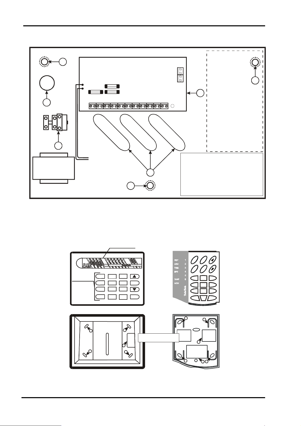
1. Security Control Panel
1
Ca60Plus
5
F - 0,63 A
3
Powering
Transformer
50 / 60 Hz
17 V / 24VA
BATT
F1
F3
F2
BATTERY
12V / 7 Ah
4
1
Fig.1 CA60Plus Security Control Panel
1
2
Transmitter
1 - Mounting holes
2 - CA60Plus Security Panel
3 - AC terminal
4 - Signal cables holes
5 - AC cable hole
Key Panel
2. LED Display Keypad
LED - displa
G
M
O
R
R
P
A
M
M
R
A
E
S
I
M
D
1
4
7
ON
1
1
3
2
5
6
89
PROG
CLEAR
1
2
0
ENTER
1
a) Cover
1 - Mounting holes
2 - Cables h ole
б) Bottom
12 3
456
789
CLR ENT
1
1
0
1
2
1
2
Fig.2 CA60Plus LED Display Keypad
4
Page 5
TeleTek CA60Plus Installation Manual
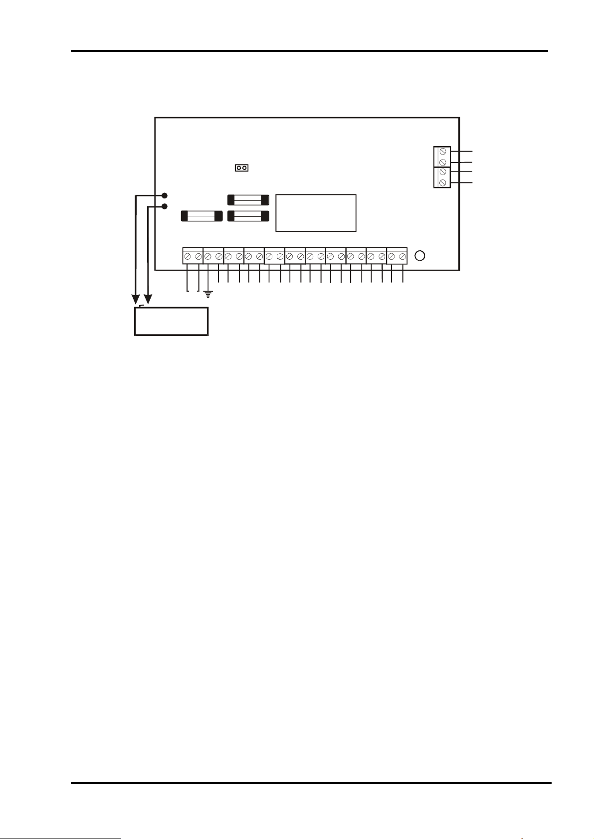
3. Inputs and Outputs
A
Reset jumper
BATT
F1
F3
F2
F1 (BATT) - 2 A
F2 ( AUX) - 1 A
F3 (PGM) - 1 A
LED
B
A1
B1
BATTERY
12 V / 7 Ah
AC
-AUX
+AUX
+PGM
PGM1
PGM2
PGM3
Z3
Z2
COM
SIREN
Z4
COM
Z5
Z6
COM
RED
GREEN
BLACK
YELLOW
Fig. 3 Inputs and Outputs
••
• AC - 17 V/24 VA AC transformer power supply
••
••
• Earth - Earthening wire
••
••
• +AUX and - AUX - 13 V DC - 1A power supply for detectors
••
••
• +PGM - 13 V DC - 1A power supply for auxilliary units
••
••
• PGM1, PGM2 and PGM3 - programmable outputs
••
••
• SIREN - siren programmable output
••
••
• Z2, Z3, Z4, Z5 and Z6 - zone inputs; (zone Z1 is in the keypad)
••
••
• COM - common shield
••
••
• A and B - to telephone company connectors
••
••
• A1 and B1 - to phone
••
••
• RED and BLACK - keypad power supply
••
••
• GREEN and YELLOW - panel - keypad interface
••
••
• F1 - battery fuse 2A
••
••
• F2 - auxilliary supply fuse 1A
••
••
• F3 - fuse 1A for powering the detectors, the programmable outputs ant the keypad
••
••
• 12 V, 7 Ah battery cables
••
5
Page 6
TeleTek CA60Plus Installation Manual
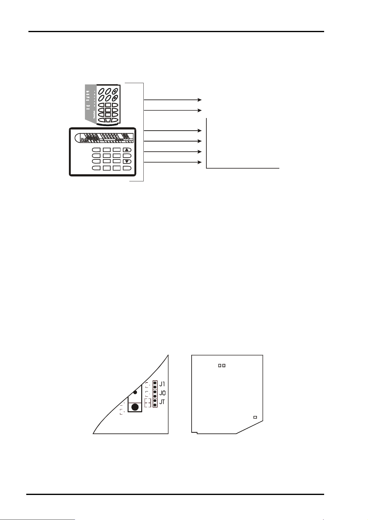
4. LED Keypad Wiring
G
M
O
R
R
P
A
M
M
R
A
E
S
I
M
D
12 3
456
789
0
CLR ENT
1
4
7
ON PROG CLEAR ENTER
3
2
5
6
89
Fig. 4Keypad - Panel Connecting
0
WHITE
BLACK
RED
GREEN
YELLOW
BLACK
ZONE 1
DETECTORS WIRES
RED
GREEN
YELLOW
BLACK
SECURITY PANEL
TERMINALS
The CA60Plus control panel keypad is wired by the manufacturer with a 20 cm long cable bundle.
While connecting the bundle to the panel have in mind the colour match of the different wires (See
Fig.4).
The cables for the zone in the keypad are white and black.
The zone in the keypad should not to balanced.
Up to three keypads may be connected in parallel to one security panel.Each keypad should be set
with his own address. This could be done by mounting a jumper in a specified place inside the keypad
(See Fig. 5).
The keypad addresses are set by jumpers:
••
• JT - the first keypad address
••
••
• J0 - the second keypad address
••
••
• J1 - the third keypad address
••
If there is only one keypad in the security panel it is obligatory that the JT jumper is installed. When
more than one keypad is used the JT jumper should be mounted in the most distant keypad.
The connecting wire between the keypad and the security panel should be no longer than 100 m
and with a section no less than 0,25 mm.
TeleTek
C A 60P lu s
keyboard
J1 J0
Rev 2.1
Rev1.3
Fig. 5 Keypad Jumper
6
JT
Page 7
TeleTek CA60Plus Instalation Manual
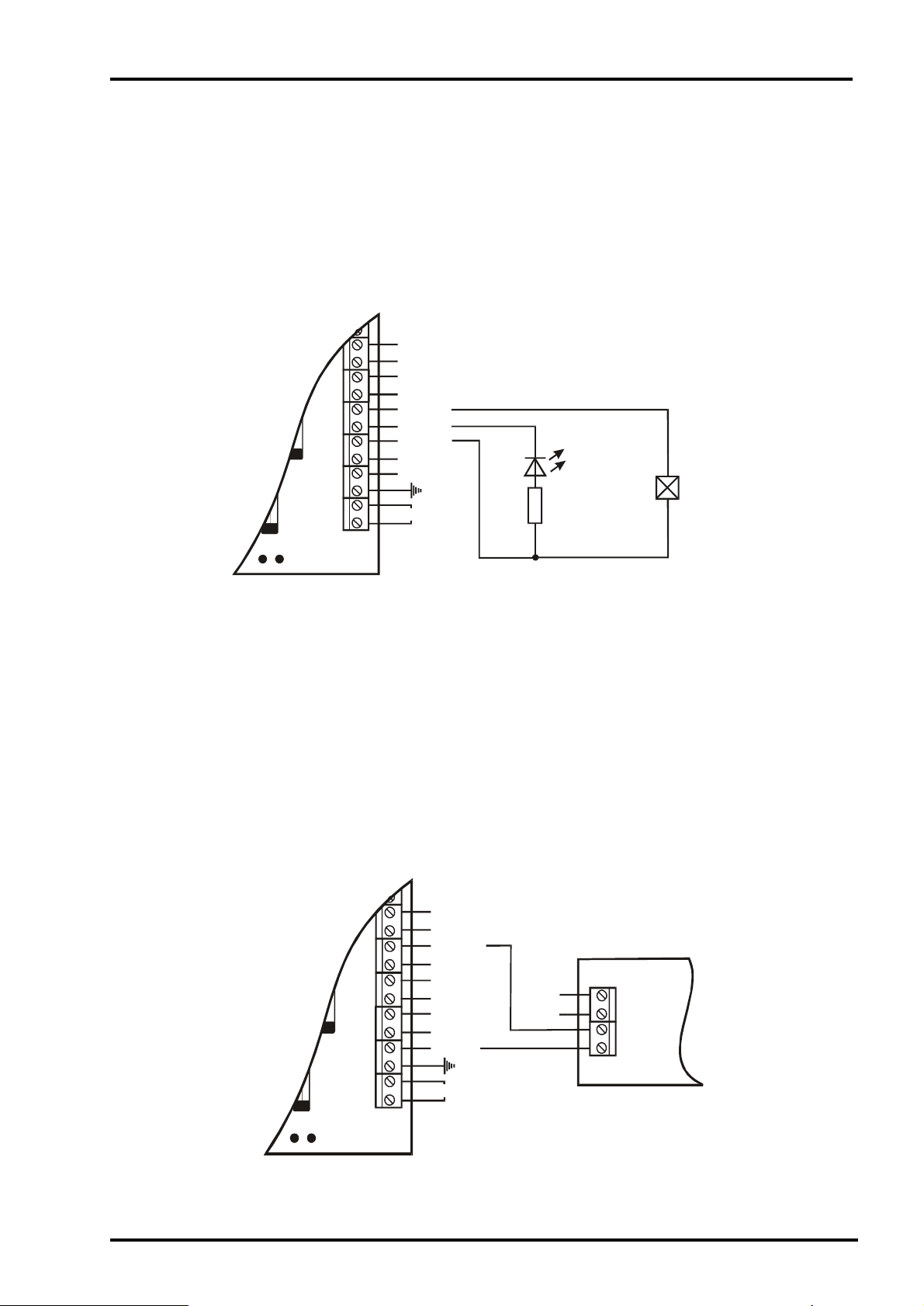
5. Programmable Outputs PGM1, PGM2 and PGM3
The PGM1, PGM2 and PGM3 security panel outputs have a programmable active level. Thus they
could be used for generating managing signals to exterior units (for example a siren with a blocking input)
or direct managing of low power exterior units (such as relays, LEDs, etc.).
The two ways of using the programmable outputs are described on Fig. 6 and Fig. 8.
Fig. 6 describes a LED and relay management through the programmable outputs PGM. The active
level of these outputs is low.
COM
Z2
SIREN
PGM3
PGM2
F2
PGM1
+PGM
-AUX
+AUX
AC
LED
RELAY
1k
CA60Plus
B
Fig. 6 LED and Relay Management by PGM1
and PGM2
6. Programmable Output SIREN
The SIREN output of the control panel is designed for siren managing. A managing signal toward a
siren with blocking input could be generated or power supply managed siren provided. The two ways of
using the SIREN output are discribed on Fig. 7 and Fig. 8.
On Fig.7 is described the SR110E siren (produced by TeleTek
been used. When an alarm event occurs the SIREN output switches to a low level and powers up the
siren SR110E.
COM
Z2
SIREN
PGM3
PGM2
F2
PGM1
+PGM
-AUX
+AUX
AC
®
) wiring. The SIREN output has
-12 V
+12 V
SR110E
CA60Plus
B
Fig. 7 Two-wires SIREN Management
7
Page 8
TeleTek CA60Plus Installation Manual
On Fig. 8 is described the SR2000 siren (produced by TeleTek®) wiring. Two managing signals are
used - SIREN and PGM3. When an alarm event occurs the SIREN output switches to a low level and
activates the SR2000 siren. When an alarm event responding to the PGM3 parameters occurs the PGM3
output switches to an active level and the SR2000 siren (depending on its configuration) activates its
signal lamp or produces a “FIRE” audible signal.
CA60Plus
B
F2
COM
Z2
SIREN
PGM3
PGM2
PGM1
+PGM
-AUX
+AUX
AC
BlkSIREN
BlkFIRE
-12 V
+12 V
SR2000
Fig. 8 Siren Management by SIREN and PGM3 Outputs
8
Page 9
TeleTek CA60Plus Installation Manual
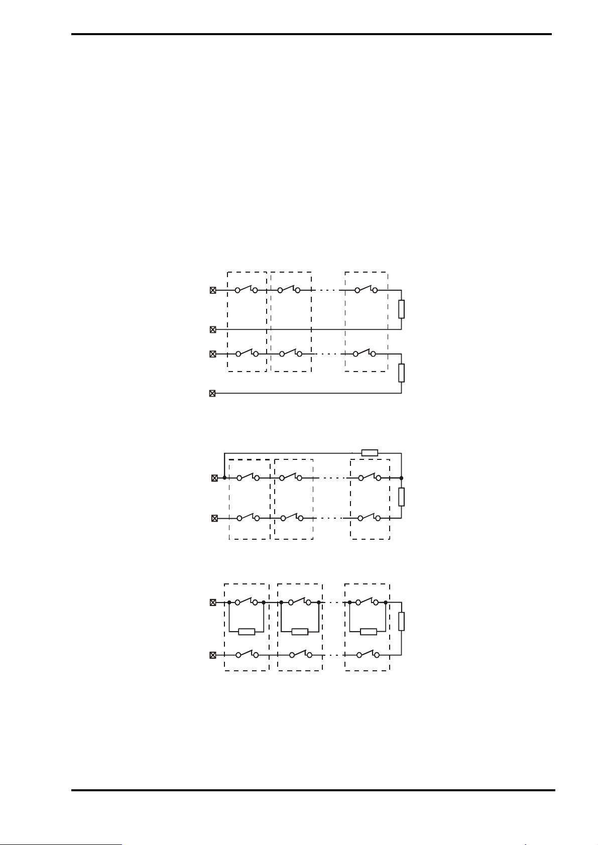
7. Detectors Wiring
The CA60 Plus control panel operates with dry relay contacts detectors. It is also possible fire detectors
with a relay output to be used.
To balance the zones use the applied 1 kΩ resistors. The balancing resistors should be housed in the
last detector in the chain.
The zones that will not be used should be terminated with a 1 kΩ resistor on the terminals regardless
the chosen zone balancing type.
After the initial powering up of the security panel the zone balancing type should be programmed. By
default the balancing is ALARM type.
On Fig. 9 a, b and c are described the possible variants of wiring the detectors and balancing the zones.
ZONE x
COM
TAM PER
ZONE
COM
NC
RELAY 1
NC
TAM P ER 1
NC
RELAY 2
NC
TAM P ER 2
NC
RELAY n
1k
NC
TAM P ER n
1k
а) Connecting Detectors with One Balancing Resistor
1k
ZONE x
COM
NC
RELAY 1NCRELAY 2
NC
TAM P ER 1
NC
TAM P ER 2
NC
RELAY n
1k
NC
TAM P ER n
b) Connecting Detectors with Two Balancing Resistors
ZONE x
COM
NC
RELAY 1NCRELAY 2
1k 1k
NC
TAM P ER 1NCTAM P ER 2
NC
RELAY n
1k
NC
TAM P ER n
1k
C) Connecting up to Four Detectors with Two Balancing Resistors
Fig. 9 Possibilities for Connecting Detectors
to the Security Panel
9
Page 10
TeleTek CA60Plus Installation Manual
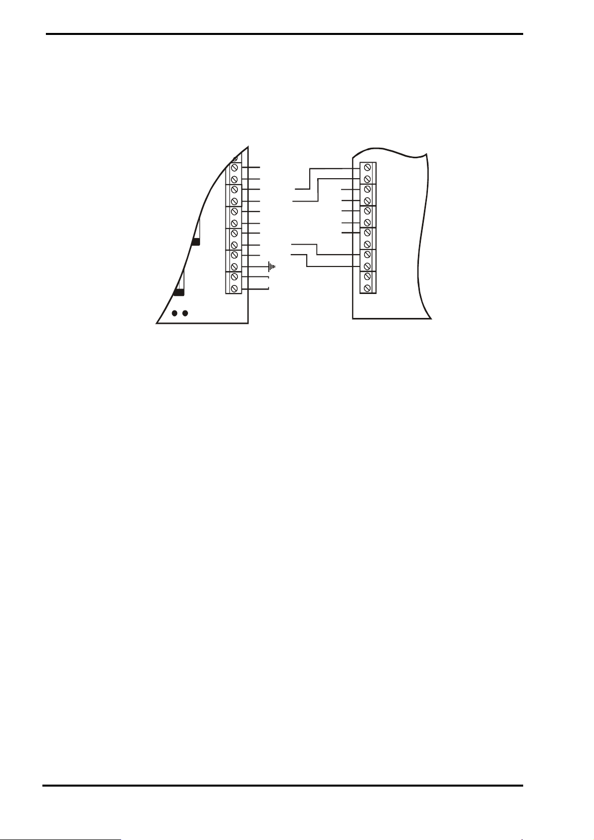
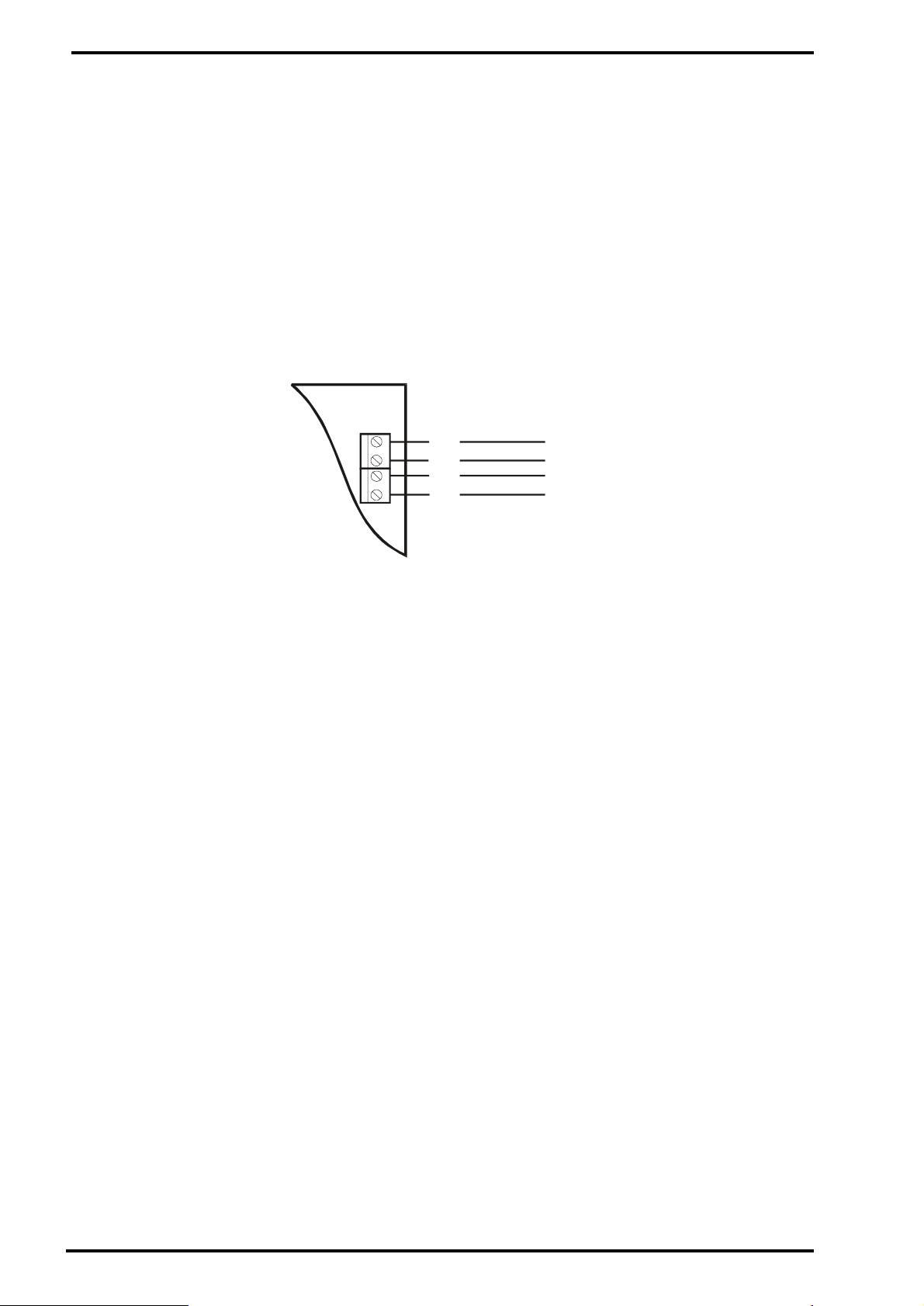
8. Internal Communicator Wiring
The telephone line is connected to A and B terminals of the CA60Plus security panel regardless the
polarity (See Fig. 10).
The phone is connected to A1 and B1 terminals of the CA60Plus security panel regardless the polarity
(See Fig. 10).
After powering up the security panel program the communicator parameters.
If the internal communicator will not be used additional units mounting is not necessary. In this case the
programming of the comunicator parameters is not advisable.
A
B
A1
B1
Phone Line
}
Phone
}
Fig.10 Internal Communicator Connection
9. Powering up the Panel
Put the RESET jumper on the CA60Plus security panel to configure the panel with the parameters set
by default by the producer.
Power up 220 V AC. The keypad will produce a short audible signal and the LEDs on the display will
flash.
Take off the RESET jumper.
Connect the battery to the security panel through the RED (+) and the BLACK (-) cable.
The normal condition of the security panel (all the detectors are non-active and there are no troubled
TAMPER circuits) is indicated on the keypad by constantly illuminating green LED READY . The
security panel is programmed with the default parameters set by the producer.
If the keypad is open or incorrectly wired all the LEDs on the display will flash an an audible signal will
be heard.
If an open zone or TAMPER is present on the display will light the respective zone LED as well as the
MEMORY or the TAMPER LED.
ATTENTION! If an open TAMPER circuit is present in the the security system the siren
will be activated. Enter 1111 code to silence the siren. The respective zone LED will illuminate
constantly, the TAMPER LED will flash. Restore the trouble - the TAMPER LED will illuminate
constantly. By entering a 0000 code erase the alarm event memory.
10
Page 11

TeleTek CA60Plus Installation Manual
PART II. Programming the CA60Plus Parameters
There are two ways to program control panel - using LED keypad and using Remote
Programmrng software “Up/Down Load”.
A. Programming the CA60Plus using LED keypad
Begin programming the control panel only after reading the following instructions carefully.
Engineer parameters programming mode of CA60Plus control panel could be activated only
when the system is disarmed.
Engineer parameters programming mode of CA60Plus control panel is activated by pressing
the PROG key once and entering an engineer code:
{PROG} -> {engineer code}
After a 2-digit address is entered the control panel parameters could be programmed. Use
the programming diagram shown on Fig. 11 and the detailed address descriptions in this manual.
The programming could be done in the order described on Fig. 11 or in an arbitrary order.
Appendix À contains a table of addresses and the panel configuration after RESET.
All the possible parameters, the indication on the keypad display and the necessary
manipulations for programming are described in details for each separate address.
The data for each address are confirmed by pressing ENTER.
When reviewing the programmed parameters the exiting of respective address by pressing
the CLEAR key once is advisable. This action will not change the existing parameters.
In case of a mistake when operating in the engineer menu it is advisable to exit the menu by
pressing the CLEAR key twice and to start the programming mode from the beginning.
B. Programming the CA60Plus using Remote Programming software “Up/Down
Load”
After installing there is a posibility to program control panel CA60Plus using Remote
Programming software in time period of 24 hours after RESET. The connection will be with
DEFAULT configuration of Up/Down Load parameters (addresses 54, 55, 56, 57, 58 and 59).
After 24 hour time period elapsed the Number of Rings parameter (address 58) becomes 0 and
remote access is imposible.
11
Page 12

TeleTek CA60Plus Installation Manual
g
PROG
Engineer Code
1 Zone Parameters
Programmable
2
Outputs Parameters
Balancing
0
1
Zone 2
2
Zone 3
3
Zone 4
4
Zone 5
5
Zone 6
6
1
2
PGM 2
3
PGM 3
4
Zone 1
PGM 1
SIREN
One Resistor/Two Resistors
Zone X Type
Entry/Exit
1
ALARM
2
PANIC
3
TAMPER
4
FIRE
5
MEDICAL
6
1
ALARM
2
PANIC
3
TAMPER
4
FIRE
5
FIRE/RST
6
ON/OFF
ALARM
1
PANIC
2
TAMPER
3
FIRE
4
Zone X Attribute
1
2
3
4
5
6
1
2
3
4
5
6
FOLLOW
DOUBLE
PAR T 1
PAR T 2
CHIME
FAST
MEDICAL
PS/bypas s
AC LOSS
BAT LOW
FUSE
Pol +/-
3
4
Times
Code System
Managment
Exit Time
0
Entry Time
1
Alarm Ti me
2
Duration
Alarm Ti me
3
Delay
Arming by a Code
0
User Code 1 Rights
1
User Code 2 Rights
2
User Code 3 Rights
3
User Code 4 Rights
4
User Code 5 Rights
5
User Code 6 Rights
6
Master Code Access t o
7
the User Codes Rights
Free Programm able Interval fro m 1 to 59 se con ds
1
1 min
2
0
0 min
1 min
1
2 min
2
3 min
3
4 min
4
5 min
5
66 min
1
2
3
4
5
6
2 min
3
3 min
4
4 min
5
5 min
66 min
Enabled/Disabled
Disarming
Arming
Arming PART 1
Arming PART 2
Event Memory Review
Zone Bypass
Enabled/Disabled
Fig. 1 1 CA60Plus Parameters Programmin
12
Page 13

TeleTek CA60Plus Installation Manual
Engineer Parameters
5
Communicator
6
Parameters
Engineer Code Change
0
1
2
3
4
5
6
7
8
9
0
1
2
3
4
5
6
7
8
Hardware Reset
Software Res et
Parti al Reset
PC Telephone Number for
Remote Programming
PC Account for
Remote Programming
Panel Account for
Remote Programming
Call Back
Number of Rings
Answering Mach i ne
Phone Number 1
Subscriber Account 1
Communication Report 1
Report Format 1
Phone Number 2
Subscriber Account 2
Communication Report 2
Report Format 2
Wait Dial Tone
Enable/Disable
Press these keys as follows
<1>, <2>, <3>, <4>, <5>, <6> and <ENTER>
Enable/Disable
Enable/Disable
Enable/Disable
Com muni cator Test
7
Parameters
Communicator
8
Event Codes
9 Test Modes
CLEAR ENGINEER MENU Exit
0
1
2
3
4
0ALARM
1
2
3
4
5
6
7
8
9
0
1
2
3
4
5
Clock Sett i ngs
Test Report Time
Auto Reporting
Test Report Code
Line Fault Indication Delay
PANIC
TAMPER
FIRE
MEDICAL
BYPASS
ON
OFF
TROUBLE
RESTORE
Walk Test
Led Test
Output Test
Com muni cator Test
Display Log
Remote Programming
Display
HH:MM
HH:MM
DD
MM
1ON/OFF PGM 1
2
ON/OFF PGM 2
34ON/OFF PGM 3
End of Communication and
0
Non-transmitted Events Erasure
ON
Previous Event
Next Event
End of Remote programming
0
ON
Fig. 11 CA60Plus Parameters Programming - continue
13
Page 14

TeleTek CA60Plus Installation Manual
1. Zone Configuration
ADDRESS 10 ZONE BALANCING TYPE
In this address the zone balancing type is set. Each pressing of a digit key alters
the balancing type. The display indication is described in the table.
ALARM One balancing resistor. The LEDs from 1 to 6 light.
DUAL Two balancing resistors. The LEDs from 1 to 6 do not light.
DEFAULT : ALARM
ADDRESS 11 ZONE 1 - TYPE AND A TTRIBUTES
This address includes two submenus. In the first one is set the type of the zone,
in the second one - its attributes. The switching between the submenus is done
by the arrow keys.
ZONE 1 TYPE SUBMENU
In this submenu for a certain zone only one type could be chosen. The choice is
done by pressing a digit number corresponding to the number of the desired
type.
1 ENTRY/EXIT Entry/Exit zone
2 ALARM Alarm zone
3 PANIC 24 hour Panic zone
4 TAMPER 24 hour Tamper zone
5 FIRE 24 hour Fire zone
6 MEDICAL 24 hour Medical zone
ZONE 1 A TTRIBUTES SUBMENU
In this submenu the attributes for ZONE 1 are chosen. The zone could have
more than one attribute. Each attribute is activated/desactivated alternately by
pressing a digit key with the respective number. The attribute is active when the
respective LED lights. At the end of the procedure on the display should light
only the LEDs corresponding to the desired attributes.
1 FOLLOW Follow zone
2 DOUBLE KNOCK Double knock zone
3PART1 Part 1 zone
4PART2 Part 2 zone
5 CHIME Chime mode
6 FAST Fast zone
DEFAULT : Entry/Exit type with PART1 and CHIME attributes
ADDRESS 12 ZONE 2 - TYPE AND A TTRIBUTES
Programming as in address 11.
DEFAULT : ALARM type with FOLLOW attribute
ADDRESS 13 ZONE 3 - TYPE AND A TTRIBUTES
Programming as in address 11.
DEFAULT : ALARM type with PART2 attributes
ADDRESS 14 ZONE 4 - TYPE AND A TTRIBUTES
Programming as in address 11.
DEFAULT : ALARM type with PART2 attributes
14
Page 15

TeleTek CA60Plus Installation Manual
ADDRESS 15 ZONE 5 - TYPE AND A TTRIBUTES
Programming as in address 11.
DEFAULT : PANIC type
ADDRESS 16 ZONE 6 - TYPE AND A TTRIBUTES
Programming as in address 11.
DEFAULT : TAMPER type
The zone types options and attributes are listed in Table 1
Table 1. Zone types and attributes
ENTRY/EXIT This zone provides time for arming and disarming the area.
When the system is armed, an activated detector in this zone will not cause an
alarm until the programmed EXIT TIME is expired.
When the armed zone is disturbed, the alarm will not be activated until the
programmed ENTRY TIME is expired.
When the ENTRY/EXIT TIME is running, an audible signal from the keypad
buzzer is heard.
ALARM This is an instant zone which could be activated only under Security Mode. It
activates the PGMs and the SIREN output having ALARM attributes and the
communicator.
When the zone is activated, the MEMORY LED and the zone LED light. After
disarming the system these LEDs continue lighting until a user code is entered
or the system is armed again.
In disarmed condition of the system the active status of this zone is indicated by
the respective LED flashing while the zone is open.
PANIC Silent Panic - only the programmable PANIC type outputs and the
communicator are activated. When the zone is activated, the respective LED
flashes. There is no memory indication. When a valid user code is entered the
MEMORY LED and the zone LED illuminate constantly. The memory is erased
either by reentering a valid user code or when the system is armed again.
Audible Panic - activates the PGMs and the SIREN output having ALARM
and/or PANIC attributes and the communicator. The sirens are instantly activated
regardless the programmed delay time. When the zone is activated, the
MEMORY LED and the zone LED illuminate constantly. The memory is erased
either by reentering a valid user code or when the system is armed again.
TAMPER The active status of this zone type activates the SIREN output, the TAMPER
programmed outputs and the communicator.
When the area is disarmed and the TAMPER siren output is programmed as
“silent”, the TAMPER activation will cause the keypads buzzer to produce an
audible signal.
When the zone is activated, the TAMPER LED and the zone LED illuminate
constantly. The memory is erased only by entering an engineer or a master
code. Constantly open TAMPER is indicated by flashing LED TAMPER.
FIRE Allows the connecting of 12 V fire detectors to the system. They should have a
normally closed dry contacts in passive condition and an open circuit in alarm
condition.
When the detector is activated, the SIREN output, the FIRE type proggrammed
outputs and the communicator are activated.
When the zone is activated the MEMORY LED flashes and the zone LED
illuminates constantly regardless the operating mode of the system.
The memory is erased either by reentering a valid user code or when the system
is armed.
15
Page 16

TeleTek CA60Plus Installation Manual
MEDICAL When this zone type is activated, the MEDICAL type programmed outputs and
the communicator are activated. Regardless the status of the system, the LED
of the activated zone lights. The memory is erased either by reentering a valid
user code or when the system is armed.
FOLLOW The ALARM type zones could be programmed as FOLLOW zones. When the
ENTRY/EXIT TIME is running the user may enter this zone type without
activating the alarm. Otherwise the alarm starts immediately.
DOUBLE KNOCK The ALARM type zones could be programmed as DOUBLE KNOCK zones.
When a signal for activating a DOUBLE KNOCK zone occurs, a 3-minutes
time window starts running. If any zone is activated before the 3-minutes period
is expired, the alarm starts. If no alarm activation occurs in this time window,
the first activation is ignored. If the zone remains active for more than 15 sec
the alarm starts immediately.
PART1 Zone with PART1 attribute enters Partial Security Mode (PART SET1). The
zones with no such attribute are bypassed. The attribute is valid for ALARM or
ENTRY/EXIT type zones.
PART2 Zone with PART2 attribute enters Partial Security Mode (PART SET2). The
zones with no such attribute are bypassed. The attribute is valid for ALARM
or ENTRY/EXIT type zones.
CHIME In disarmed status of the system the activation of a zone with the CHIME
attribute causes a specific audible signal from the keypads. When the system is
armed, this zone acts as an ordinary ALARM or ENTRY/EXIT type zone. The
attribute is valid for the ALARM or ENTRY/EXIT type zones.
FAST When this attribute is set to certain zone, the time for scanning the entry signal
is reduced for the ALARM and ENTRY/EXIT type zones. This allows vibration
detectors without an analyser to be connected to this zone.
16
Page 17

TeleTek CA60Plus Installation Manual
2. PGM AND SIREN PROGRAMMABLE OUTPUTS CONFIGURATION
ADDRESS 21 PGM1 PROGRAMMABLE OUTPUT
In this address the events which will force the programmable output to move
into an active level are programmed.
A free combination of events activating the programmable output is allowed.
The output is activated whenever a programmed event occurs (function logical
OR) and is restored when all the programmed events are restored (function
logical AND).
Press the digit number corresponding to the desired parameter. If the LED with
the same number lights the parameter is set.
To switch between the first and the second group of parameters use the arrow
keys.
PGM1 PROGRAMMABLE OUTPUT - FIRST GROUP OF
P ARAMETERS
1 ALARM Activated when an intervention into ALARM or ENTRY/EXIT zones under
Security Mode occurs. The output is restored by entering a valid user code or
automatically after 1 min.
3 PANIC Activated when a PANIC type zone or the PANIC keys combination are
activated. The output is restored by entering a valid user code.
3 TAMPER Activated when the tamper of a zone or a TAMPER type zone are activated
regardless the status of the system - armed or disarmed. The output is restored
when the tamper is restored.
4 FIRE Activated when a FIRE type zone is activated. The output is restored by entering
a valid code.
5 FIRE RST Activated for 4 seconds after entering a valid code.
6 ÎN/OFF Activated when the system is armed. The output is restored when the system is
disarmed.
PGM1 PROGRAMMABLE OUTPUT - SECOND GROUP OF
P ARAMETERS
1 MEDICAL Activated when a MEDICAL type zone is activated. The output is restored by
entering a valid user code.
2 PS/Bypass Activated when the system is armed with a bypassed alarm or ENTRY/EXIT
zone or a Partial Security Mode (PARTSET) is on. The output is restored when
the system is disarmed.
3 AC LOSS Activated when the 220 V AC is lost. The output is restored when the AC
power is restored.
4 BAT LOW Activated when the battery power is less than 11 V. The output is restored
when the battery power is restored.
5 FUSE Activated when any of the fuses of the panel is blown. The output is restored
when the fuse is replaced.
6 POL +/- This attribute chooses the output active level. When the “-“ is chosen (the LED
does not light) the active level is 0 V. When the “+” is chosen the output active
level is 12 V.
DEFAULT : ON/OFF, POL “+”
17
Page 18

TeleTek CA60Plus Installation Manual
ADDRESS 22 PGM2 PROGRAMMABLE OUTPUT
Programming as in address 21.
DEFAULT : ALARM, TAMPER, POL “+”
ADDRESS 23 PGM3 PROGRAMMABLE OUTPUT
Programming as in address 21.
DEFAULT : AC LOSS, BAT LOW, FUSE, POL “+”
ADDRESS 24 SIREN PROGRAMMABLE OUTPUT
The SIREN output is activated by 4 events. The active level of this output is low
(0 V) and could not be programmed.
A free combination of events activating this output is allowed. The output is
restored after the bell time - programmed in address 32 - is expired.
ALARM Activated when an intervention into ALARM or ENTRY/EXIT zones under
Security Mode occurs. The output is restored by entering a valid user or master
code or automatically after the bell time is expired.
TAMPER Activated when the tamper of a zone or a TAMPER type zone are activated
regardless the status of the system - armed or disarmed. In case the event is not
chosen to activate the SIREN output, it will cause an audible signal from the
keypads. The output is restored by entering a valid user or master code or
automatically after the bell time is expired.
PANIC Activated when a PANIC type zone or the PANIC keys combination is
activated. The output is restored by entering a valid user or master code.
FIRE Activated when a FIRE type zone is activated. The output is restored by entering
a valid code. This event ALWAYS activates the SIREN output and could
not be cancelled.
DEFAULT : ALARM, PANIC, TAMPER, FIRE/ALW
18
Page 19

TeleTek CA60Plus Installation Manual
3. TIMES
ADDRESS 30 EXIT TIME PROGRAMMING
EXIT TIME The EXIT TIME for the ENTRY/EXIT type zones is set in this address. The
number of seconds from 01 to 60 is entered. For a time period less than 10 sec
the first digit should be 0.
The lighting scale formed by the LEDs from 1 to 6 indicates the period.
Each lighting LED includes 10 seconds. For example if the LEDs 1, 2 and 3
light, the chosen time is 20 to 29 seconds.
DEFAULT : 45 seconds
ADDRESS 31 ENTRY TIME PROGRAMMING
ENTRY TIME The ENTRY time for the ENTRY/EXIT type zones is set in this address. The
number of seconds from 01 to 60 is entered. For a time period less than 10 sec
the first digit should be 0.
The lighting scale formed by the LEDs from 1 to 6 indicates the period.
Each lighting LED includes 10 seconds. For example if the LEDs 1, 2 and 3
light, the chosen time is 20 to 29 seconds.
DEFAULT : 15 seconds
ADDRESS 32 BELL TIME PROGRAMMING
BELL TIME The bell time period is set in this address. The number of minutes from 1 to 6 is
entered.
The lighting scale formed by the LEDs from 1 to 6 indicates the period. Each
lighting LED includes 1 minute.
DEFAULT : 3 minutes
ADDRESS 33 BELL DELA Y TIME PROGRAMMING
BELL DELAY The bell delay time is set in this address. The number of minutes from 1 to 6 is
entered.
The lighting scale formed by the LEDs from 1 to 6 indicates the period. Each
lighting LED includes 1 minute.
DEFAULT : 0 minutes
19
Page 20

TeleTek CA60Plus Installation Manual
4. CODE SYSTEM MANAGEMENT
ADDRESS 40 SET WITH CODE
NO Full or Partial arming of the area does not require confirmation by entering a
valid user code. The LEDs from 1 to 6 do not light.
YES Full or Partial arming of the area requires confirmation by entering a valid user
code. The LEDs from 1 to 6 light.
DEFAULT : NO
ADDRESS 41 USER CODE 1 A TTRIBUTES
In this address the USER CODE1 attributes are set. The user code could have
more than one attribute. An attribute is activated/desactivated alternately by
pressing the digit of the respective number. The choice is indicated by lighting of
the LED with the number of the pressed digit. At the end of the procedure on
the display should light only the LEDs responding to the desired attributes.
1 Unset Enables this user code to disarm the area.
2 FullSet Enables this user code to arm the area.
3 Part Set 1 Enables this user code to arm PART1 of the area.
4 Part Set 2 Enables this user code to arm PART2 of the area.
5 Log Gives this user code an access right to the event memory.
6 Bypass Gives this user code a right to bypass zones in the secured area.
DEFAULT : UNSET, FULLSET, PART SET1, PART SET2, LOG, BYPASS
ADDRESS 42 USER CODE 2 A TTRIBUTES
Programming as in address 41.
DEFAULT : No
ADDRESS 43 USER CODE 3 A TTRIBUTES
Programming as in address 41.
DEFAULT : No
ADDRESS 44 USER CODE 4 A TTRIBUTES
Programming as in address 41.
DEFAULT : No
ADDRESS 45 USER CODE 5 A TTRIBUTES
Programming as in address 41.
DEFAUL]T : No
ADDRESS 46 USER CODE 6 A TTRIBUTES
Programming as in address 41.
DEFAULT : No
ADDRESS 47 MANAGER ACCESS TO THE USER CODE A TTRIBUTES
NO The access of the manager to the user codes rights is denied.
The LEDs from 1 to 6 do not light.
YES The access of the manager to the user codes rights is allowed.
The LEDs from 1 to 6 light.
DEF AUL T : YES
20
Page 21

TeleTek CA60Plus Installation Manual
5. ENGINEER PARAMETERS
ADDRESS 50 ENGINEER CODE CHANGE
In this address a new access code to the engineer parameters of the control
panel is set. On the keypad display the LEDs: 3, 4, 5 and 6 light. After each
entering of a digit of the new code, one LED stops lighting. Confirmation of the
new code is required.
ENGINEER CODE The engineer code is programmed.
DEF AUL T : 7777
ADDRESS 51 HARDW ARE RESET BLOCKING
In this address the hardware RESET of the control panel is enabled/disabled.
In case the hardware RESET is disabled and the engineer code is
unknown, the programming menu is not accessible.
NO The hardware RESET is disabled. The LEDs from 1 to 6 do not light.
YES The hardware RESET is enabled. The LEDs from 1 to 6 light.
DEF AUL T : YES
ADDRESS 52 DEFF AUL T P ARAMETERS RESETTING (SOFTW ARE RESET)
DEFAULT Control panel default parameters reseting. The 1, 2, 3, 4, 5, 6 keys are pressed
SETTINGS in sequence and confirmed by ENTER. The system begins charging the default
parameters.
ADDRESS 53 DEFF AUL T MANAGER CODE RESETTING
DEFAULT Control panel default manager code (0000) reseting. The 1, 2, 3, 4, 5, 6 keys are
MANAGER CODE pressed in sequence and confirmed by ENTER. The system recharges the
default manager code.
ADDRESS 54 PHONE NUMBER FOR REMOTE PROGRAMMING
Tel No for In this address the phone number for remote programming from the remote PC
Up / Down Load is set. Hexadecimal indication. The maximum lenght of the phone number is 16
symbols, including the pause symbols (ON and 2) and the symbols for entering
a DTMF dialing (ON and 1).
DEFAULT : No phone number entered
ADDRESS 55 REMOTE PC ACCOUNT NUMBER FOR REMOTE
PROGRAMMING
In this address a remote PC account number for remote programming is set. On
the keypad display the LEDs: 3, 4, 5 and 6 light. After each entering of a digit of the
new account, one LED stops lighting. Confirmation of the new account is required.
PC ID The remote PC account number for remote programming is programmed.
DEF AUL T : 1234
ADDRESS 56 CONTROL P ANEL ACCOUNT NUMBER FOR REMOTE
PROGRAMMING
In this address a control panel account number for remote programming panel is set.
On the keypad display the LEDs: 3, 4, 5 and 6 light. After each entering of a digit of
the account, one LED stops lighting. Confirmation of the new account is required.
PANEL ID The control panel account number for remote programming is programmed.
DEF AUL T : 1234
21
Page 22

TeleTek CA60Plus Installation Manual
ADDRESS 57 CALL BACK OPTION
In this address the Call Back option for remote programming is set. Each
pressing of a digit key alters the Call Back option enable / disable.
If Call Back option enabled, after an incoming call and request for remote
programming, control panel hangs up and dials the number of remote PC. After
connecting to remote PC the remote programming starts.
The display indication is described in the table.
YES Call Back option enabled. The LEDs from 1 to 6 light.
NO Call Back option disabled. The LEDs from 1 to 6 do not light.
DEFAULT : NO
ADDRESS 58 NUMBER OF RINGS
In this address the Number of Rings before control panel answers for remote
programming is set.
NUMBER OF The symbols from 0 to 9 could be used.
RINGS If 0 entered the remote programming is disabled.
It is recommended to enter value up to 7.
DEFAULT : 7
ADDRESS 59 ANSWERING MACHINE OPTION
In this address the Answering Machine option for remote programming is set.
Each pressing of a digit key alters Answering Machine option enable / disable.
If there is an answering machine (FAX for example) on the same telephone line
it is necessary to ensure connection to it. Therefore the Answering Machine
option has to be enabled. On the first incoming call series the control panel will
not answer. On each next incoming call for 4 minutes time period the control
panel will answer.
The display indication is described in the table.
YES Answering Machine option enabled. The LEDs from 1 to 6 light.
NO Answering Machine option disabled. The LEDs from 1 to 6 do not light.
DEFAULT : NO
22
Page 23

TeleTek CA60Plus Installation Manual
6. COMMUNICATOR PARAMETERS
Before configuring the communicator call your Monitoring company and specify
the necessary parameters - phone numbers, the subscriber account number,
communication report and event codes.
Before starting to configure the parameters erase the non-transmitted codes
from the event buffer in address 93 by pressing the 0 key once.
ADDRESS 60 PRIMAR Y PHONE NUMBER (PHONE 1)
Tel No 1 In this address the primary phone number for communication with the monitoring
station is set. Hexadecimal indication. The maximum lenght of the phone number
is 16 symbols, including the pause symbols (ON and 2) and the symbols for
entering a DTMF dialing (ON and 1).
DEFAULT : No phone number entered
ADDRESS 61 SUBSCRIBER ACCOUNT NUMBER 1
PANEL ID 1 This is the panel ID number for the primary monitoring station. The lenght of
the number is 3 or 4 digits (depending on the report format - 3x or 4x). The 0
symbol is replaced by an A (See the hexadecimal programming table in Appendix
A).
DEF AUL T : 9999
ADDRESS 62 COMMUNICA TION REPORT 1
COMMUNICATION The communication report types to the monitoring station are listed in the table
REPORT 1 below. The symbols from 0 to B could be used.
[0] User report - dialer
[1] SP=10 pps; HS=KO=1400Hz; Data=1900Hz; 3x1, 3x2, 4x1, 4x2;
[2] SP=10 pps; HS=KO=1400Hz; Data=1900Hz; EXT; 3x1, 4x1;
[3] SP=20 pps; HS=KO=1400Hz; Data=1900Hz; 3x1, 3x2, 4x1, 4x2;
[4] SP=20 pps; HS=KO=1400Hz; Data=1900Hz; EXT; 3x1, 4x1;
[5] SP=20 pps; HS=KO=2300Hz; Data=1800Hz; 3x1, 3x2, 4x1, 4x2;
[6] SP=20 pps; HS=KO=2300Hz; Data=1800Hz; EXT; 3x1, 4x1;
[7] SP=40 pps; HS=KO=2300Hz; Data=1800Hz; 3x1, 4x2;
[8] SP=40 pps; HS=KO=2300Hz; Data=1800Hz; EXT; 3x1;
[9] SP=40 pps; HS=KO=2300Hz; Data=1800Hz; 3x1, 4x2; Checksum;
[A] SP=40 pps; HS=KO=2300Hz; Data=1800Hz; EXT; 3x1; Checksum;
[B] ADEMCO CONTACT ID
[C]…[F] - reserved for future use
DEFAULT : 1
ADDRESS 63 REPORT FORMA T 1
x1 Choosing the format of the set report 3x1, 4x1. The LEDs from 1 to 6 light.
x2 Choosing the format of the set report 3x2, 4x2. The LEDs from 1 to 6 do not
light.
DEF AUL T : x2
ADDRESS 64 SECONDAR Y PHONE NUMBER (PHONE 2)
Tel No 2 In this address the secondary phone number for communication with the
monitoring station is set. Hexadecimal indication. The maximum lenght of the
phone number is 16 symbols, including the pause symbols (ON and 2) and the
symbols for entering a DTMF dialing (ON and 1).
DEFAULT : No entered phone number
23
Page 24

TeleTek CA60Plus Installation Manual
ADDRESS 65 SUBSCRIBER ACCOUNT NUMBER 2
PANEL ID 2 This is the panel ID number for the secondary monitoring station. The lenght of
the number is 3 or 4 digits (depending on the report format - 3x or 4x). The 0
symbol is replaced by an A (See the hexadecimal programming table in Appendix
A).
DEF AUL T : 9999
ADDRESS 66 COMMUNICA TION REPORT 2
COMMUNICATION The communication report types to the monitoring station are listed in the table
REPORT 2 below. The symbols from 0 to B could be used.
[0] User report - dialer
[1] SP=10 pps; HS=KO=1400Hz; Data=1900Hz; 3x1, 3x2, 4x1, 4x2;
[2] SP=10 pps; HS=KO=1400Hz; Data=1900Hz; EXT; 3x1, 4x1;
[3] SP=20 pps; HS=KO=1400Hz; Data=1900Hz; 3x1, 3x2, 4x1, 4x2;
[4] SP=20 pps; HS=KO=1400Hz; Data=1900Hz; EXT; 3x1, 4x1;
[5] SP=20 pps; HS=KO=2300Hz; Data=1800Hz; 3x1, 3x2, 4x1, 4x2;
[6] SP=20 pps; HS=KO=2300Hz; Data=1800Hz; EXT; 3x1, 4x1;
[7] SP=40 pps; HS=KO=2300Hz; Data=1800Hz; 3x1, 4x2;
[8] SP=40 pps; HS=KO=2300Hz; Data=1800Hz; EXT; 3x1;
[9] SP=40 pps; HS=KO=2300Hz; Data=1800Hz; 3x1, 4x2; Checksum;
[A] SP=40 pps; HS=KO=2300Hz; Data=1800Hz; EXT; 3x1; Checksum;
[B] ADEMCO CONTACT ID
[C]…[F] - reserved for future use
DEFAULT : 1
ADDRESS 67 REPORT FORMA T 2
x1 Choosing the format of the set report 3x1, 4x1. The LEDs from 1 to 6 light.
x2 Choosing the format of the set report 3x2, 4x2. The LEDs from 1 to 6 do not
light.
DEFAULT : x2
ADDRESS 68 WAIT DIAL TONE
NO Do not wait for DIAL tone before dialing. The LEDs from 1 to 6 do not light.
YES Wait for DIAL tone before dialing. The LEDs from 1 to 6 light.
DEFAULT : YES
24
Page 25

TeleTek CA60Plus Installation Manual
7. COMMUNICATOR TEST PARAMETERS
ADDRESS 70 SYSTEM CLOCK SETTINGS
CLOCK In this address the hour and minutes are set (HH:MM). The indication is
hexadecimal and the digits show up one by one. The digits are monitored by the
arrow keys.
DEFAULT : 00:00 h
ADDRESS 71 TEST REPORT TIME
TEST TIME In this address the hour for transmission the test message to the monitoring
station is chosen. Hour and minutes are set (HH:MM). Hexadecimal indication.
DEFAULT : 14:01 h
ADDRESS 72 AUT O REPORTING
TEST PERIOD In this address the period for test message transmission is set in days (DD).
Hexadecimal indication. T wo digit numbers should be used. When a period
less than 10 days is chosen the first digit should be 0.
DEFAULT : 01 day
ADDRESS 73 TEST REPOR T CODE
TEST CODE The first symbol of the “test report” event code is set (X). The panel transmits
as a second symbol a copy of the first. Hexadecimal indication.
DEFAULT : A
ADDRESS 74 LINE F AUL T INDICA TION DELAY
LF DELAY Delay time in minutes (MM) before the indication for LF is set. Hexadecimal
indication. Two digit numbers should be used. When a period lesser than
10 minutes is chosen the first digit should be 0. If an indication for LF is
not necessary, 00 should be entered.
DEFAULT : 00 minutes
25
Page 26

TeleTek CA60Plus Installation Manual
8. COMMUNICATOR EVENT CODES
For the Report Codes only the first symbol should be entered. The second is
automatically generated by the security panel.
If the symbol 0 is entered as a code, the respective event will not be transmitted
by the communicator.
Consult your Monitoring company about the event codes.
ADDRESS 80 ALARM REPOR T CODE
ALARM CODE ALARM Report Code (X). Hexadecimal indication. The zone number is
automatically added before sending the message to the monitoring station.
DEFAULT : 1
ADDRESS 81 P ANIC REPORT CODE
PANIC CODE PANIC Report Code (X). Hexadecimal indication. The zone number is
automatically added before sending the message to the monitoring station.
DEFAULT : 2
ADDRESS 82 T AMPER REPORT CODE
TAMPER CODE TAMPER Report Code (X). Hexadecimal indication. The zone number is
automatically added before sending the message to the monitoring station.
DEFAULT : 3
ADDRESS 83 FIRE REPORT CODE
FIRE CODE FIRE Report Code (X). Hexadecimal indication. The zone number is
automatically added before sending the message to the monitoring station.
DEFAULT : 4
ADDRESS 84 MEDICAL REPORT CODE
MEDICAL CODE MEDICAL Report Code (X). Hexadecimal indication. The zone number is
automatically added before sending the message to the monitoring station.
DEFAULT : 5
ADDRESS 85 BYP ASS REPORT CODE
BYPASS CODE BYPASS Report Code (X). Hexadecimal indication. The zone number is
automatically added before sending the message to the monitoring station.
DEFAULT : 6
26
Page 27

TeleTek CA60Plus Installation Manual
ADDRESS 86 ARM REPORT CODE
ARM CODE Arm Report code (X). Hexadecimal indication. The code number is added
automatically before transmitting the message to the monitoring station.
DEFAULT : 7
ADDRESS 87 DISARM REPORT CODE
DISARM CODE Disarming Report code (X). Hexadecimal indication. The code number is added
automatically before transmitting the message to the monitoring station.
DEFAULT : 8
ADDRESS 88 TROUBLE REPORT CODE
TROUBLE CODE Trouble Report code (X). Hexadecimal indication. The number of the respective
trouble is added automatically before transmitting the message to the monitoring
station as follows:
x1. Blown Fuse F3 - PGM
x2. Blown Fuse F2 - AUX
x3. LOW BATT
x4. AC LOSS
x5. Non trasmitted
x6. Communication Fault
x7. RESTORE “LOW BATT”
x8. RESTORE “AC LOSS”
DEFAULT : 9
ADDRESS 89 RESTORE REPORT CODE
RESTORE CODE Zone Restore Report code (X). Hexadecimal indication. The number of the
respective trouble is added automatically before transmitting the message to the
monitoring station.
DEFAULT : B
27
Page 28

TeleTek CA60Plus Installation Manual
9. CA60Plus TEST MODES
ADDRESS 90 WALK TEST
WALK TEST Allows functional zone test. Under this mode the respective activated zone
LED flashes. If an open tamper is present the respective zone LED illuminates
constantly.
ADDRESS 91 KEYP AD TEST
LED TEST Tests the reliability of the LEDs and the keypad buzzer.
ADDRESS 92 PGM1, PGM2, PGM3 and SIREN OUTPUTS TEST
OUTPUT TEST PGMs functional test is performed by pressing the key, corresponding to the
respective programmable output. The respective LED illuminates constantly
and the output enters a low level - 0 V. The next pressing of the same key
forces the output to enter a high level - 12 V.
1 PGM1
2 PGM2
3 PGM3
4 SIREN
ADDRESS 93 COMMUNICA TOR MONITOR
COMMUNICATOR In this address the functioning of the communicator could be monitored directly.
MONITOR Pressing the ON key starts test transmission from the communicator to the
monitoring station. Pressing the 0 key interrupts the current communication and
erases the non-transmitted events. To exit the address press CLEAR. The LEDs
indication is as follows:
ZONE1: · flashes - waiting for dial tone in process
· illuminates constantly - the process is over
ZONE2: · flashes - phone number dialing in process
· illuminates constantly - the process is over
ZONE3: · flashes - waiting for HANDSHAKE from the monitoring station
in process
· illuminates constantly - the process is over
ZONE4: · flashes - message transmition to the monitoring station in process
· illuminates constantly - the process is over
ZONE5: · flashes - waiting for a confirmation from the monitoring station in
process
· illuminates constantly - the process is over
ZONE6: · illuminates constantly - the communication process is over
After the communication has ended successfully the keypad produces an
audible signal
ADDRESS 94 LOG FILE REVIEW
DISPLAY LOG With the help of the arrow keys the events registered in the memory of the
panel are reviewed. The first visualized event is the last registered.
28
Page 29

TeleTek CA60Plus Installation Manual
APPENDIX A
RESET Parameters Table
PROGRAM MENU ADDRESS LE D 1 LED 2 LED 3 L ED 4 L ED 5 LE D 6
LOOP TYPE 10 DUAL - LED1 to LED6 do not ligh t ALARM - LED1 to LED6 light
ZONE 1 11 ! En try /Exit ALA RM PA NIC TAM PER FIRE MEDICA L
ATTRIBUTES ZONE 1 " FOLLOW DOUBLE PART1 PART2 CHIME FAST
ZONE 2 12 ! En try /Exit ALA RM PA NIC TAM PER FIRE MEDICA L
ATTRIBUTES ZONE 2 " FOLLOW DOUBLE PART1 PART2 CHIME FAST
ZONE 3 13 ! En try /Exit ALA RM PA NIC TAM PER FIRE MEDICA L
ATTRIBUTES ZONE 3 " FOLLOW DOUBLE PART1 PART2 CHIME FAST
ZONE 4 14 ! En try /Exit ALA RM PA NIC TAM PER FIRE MEDICA L
ATTRIBUTES ZONE 4 " FOLLOW DOUBLE PART1 PART2 CHIME FAST
ZONE 5 15 ! En try /Exit ALA RM PA NIC TAM PER FIRE MEDICA L
ATTRIBUTES ZONE 5 " FOLLOW DOUBLE PART1 PART2 CHIME FAST
ZONE 6 16 ! En try /Exit ALA RM PA NIC TAM PER FIRE MEDICA L
ATTRIBUTES ZONE 6 " FOLLOW DOUBLE PART1 PART2 CHIME FAST
PGM 1 21 ! ALARM PANIC TAMPER FIRE FIRE/RST ON/OFF
" MEDICAL PS/bypass AC L OSS BA T LOW FUSE P ol + / -
PGM 2 22 ! ALARM PANIC TAMPER FIRE FIRE/RST ON/OFF
" MEDICAL PS/bypass AC L OSS BA T LOW FUSE P ol + / -
PGM 3 23 ! ALARM PANIC TAMPER FIRE FIRE/RST ON/OFF
" MEDICAL PS/bypass AC L OSS BA T LOW FUSE P ol + / -
SIREN OUTPUT 24 ALARM PANIC TAMPER FIRE/ALW
EXIT TIME 30 0-9 SEC 10-19 SEC 20-29 SEC 30-39 SEC 40-49 SEC 50 - 59 SEC
ENTRY TIME 31 0-9 SEC 10-19 SEC 20-29 SEC 30-39 SEC 40-49 SEC 50 - 59 SEC
BELL TIME 32 1 MIN 2 MIN 3 MIN 4 MIN 5 MIN 6 MIN
BELL DELAY 33 1 MIN 2 MIN 3 MIN 4 MIN 5 MIN 6 MIN
SET W ITH CODE 40 NO - LED1 to LED6 do n ot ligh t YES - LED1 t o LED6 light
USER CODE 1 41 UNSET FULSET PARTSET1 PARTSET2 LOG BYPASS
USER CODE 2 42 UNSET FULSET PARTSET1 PARTSET2 LOG BYPASS
USER CODE 3 43 UNSET FULSET PARTSET1 PARTSET2 LOG BYPASS
USER CODE 4 44 UNSET FULSET PARTSET1 PARTSET2 LOG BYPASS
USER CODE 5 45 UNSET FULSET PARTSET1 PARTSET2 LOG BYPASS
USER CODE 6 46 UNSET FULSET PARTSET1 PARTSET2 LOG BYPASS
MA NGER ACCESS 47 NO - LED1 to LED6 do no t ligh t YES - LED1 t o LED6 ligh t
ENGINEER CODE 50 DIGIT 1 DIGIT 2 DIGIT 3 DIGIT 4
RESET ENABLE 51 NO - LED1 t o LED6 d o no t ligh t YES - LED1 to LED6 lig h t
DEFAULT SETTINGS 52 Press the keys from 1 to 6 consequently and confirm by ENTER
PART. RESET 53 Press the keys from 1 to 6 consequently and confirm by ENTER
54 to 89 address indication, con c e rning th e commun ic ator parameter s, is he xadecimal, the L EDs 3,4,5,6 are
used (Lower BIT - LED 6)
TEL No PC FOR UDL
PC ID FOR UDL
PA NEL ID FOR UDL
CALL BACK NO - LED1 to LED6 do no t ligh t YES - LED1 to LED6 lig ht
No OF RINGS
ANSW . MA CHINE NO - LED1 to LED6 do no t ligh t YES - LED1 to LED6 lig ht
TEL No 1 60 Max phone number lenght 16 symbols, pause=ON+2, DTMF =ON+1
PANEL ID 1 61 3 or 4 digits (depending on the report 3х or 4х)
REPORT 1 62 The report number included in the applied table is entered
х1/х2 63 x2 - LED1 to LED6 do not light x1 - LED1 to LED6 light
TEL No 2 64 Max phone number lenght 16 symbols, pause=ON+2, DTMF =ON+1
PANEL ID 2 65 3 or 4 digits (depending on the report 3х or 4х)
REPORT 2 66 The report number included in the applied table is entered
х1/х2 67 x2 - LED1 to LED6 do not light x1 - LED1 to LED6 light
WA IT DIA L TONE 68 NO - LED1 t o LED6 do no t light YES - LED1 to LED6 lig h t
54
55
56
57
58
59
Max phone number lenght 16 symbols, pause=ON+2, DTMF =ON+1
4 digits. Default 1234
4 digits. Default 1234
1 digit. (0 to 9)
RESET Parameters
29
Page 30

TeleTek CA60Plus Installation Manual
PROGRAM MENU ADDRESS LED 1 LED 2 LED 3 LED 4 LED 5 LED 6
CLOCK 70 Clock Settings ( HH:MM)
TEST TIME 71 Test peport time ( HH:MM)
TEST PERIOD 72 Auto reporting(DD)
TEST CODE 73 TEST code. RESET A value.
LF DELAY 74 LF delay indication (ММ)
ALARM CODE 80 ALARM Report code. RESET Value 1.
PANIC CODE 81 PA NIC Rep ort co d e. RESET Value 2.
TAMPER CODE 82 TAMPER Report code. RESET Value 3.
FIRE CODE 83 FIRE Report code. RESET Value 4.
MEDICA L CODE 84 M EDICAL Report co de. RESET Value 5.
BYPASS CODE 85 BYPASS Report code. RESET Value 6.
ON CODE 86 ON Report code. RESET Value 7.
OFF CODE 87 OFF Report code. RESET Value 8.
TROUBLE CODE 88 TROUBLE Repo rt cod e. RESET Value 9.
RESTORE CODE 89 RESTORE Report cod e . RESET Value B.
WALK TEST 90 ZONE 1ZONE 2ZONE 3ZONE 4ZONE 5ZONE 6
LED TEST 91
OUTPUTS TEST 92 PGM1 PGM2 PGM3 SIREN
COMMUNIC.DISPLAY 93 Dial Tone Dialing W ait HS Send Data Wait Koff All Sent
DISPLAY LOG 94
Up/Down Load Display 95 Ring Dialing
LOG File Rev iew
Wait
Carrier
Send Data
Rece ive
Data
Value L E Ds Status Key
LED 3 LED 4 LED 5 LED 6 combination
A
B
C
D
0
1
2
3
4
5
6
7
8
9
E
F
ΟΟΟΟΟ
ΟΟΟΟΟ
ΟΟΟΟΟ
ΟΟΟΟΟ
ΟΟΟΟ⊗
ΟΟΟΟ⊗
ΟΟΟΟ⊗
ΟΟΟΟ⊗
⊗⊗⊗⊗Ο
⊗⊗⊗⊗Ο
⊗⊗⊗⊗Ο
⊗⊗⊗⊗Ο
⊗⊗⊗⊗⊗
⊗⊗⊗⊗⊗
⊗⊗⊗⊗⊗
⊗⊗⊗⊗⊗
ΟΟ
ΟΟ
ΟΟ
ΟΟ
Ο⊗
ΟΟ
Ο⊗
ΟΟ
⊗Ο
⊗⊗
⊗Ο
⊗⊗
⊗⊗
⊗⊗
⊗⊗
⊗⊗
ΟΟ
ΟΟ
ΟΟ
ΟΟ
Ο⊗
ΟΟ
Ο⊗
ΟΟ
⊗Ο
⊗⊗
⊗Ο
⊗⊗
⊗⊗
⊗⊗
⊗⊗
⊗⊗
ΟΟ
ΟΟ
Ο⊗
ΟΟ
⊗Ο
⊗⊗
⊗⊗
⊗⊗
ΟΟ
ΟΟ
Ο⊗
ΟΟ
⊗Ο
⊗⊗
⊗⊗
⊗⊗
ΟΟ
ΟΟ
Ο⊗
ΟΟ
⊗Ο
⊗⊗
⊗⊗
⊗⊗
ΟΟ
ΟΟ
Ο⊗
ΟΟ
⊗Ο
⊗⊗
⊗⊗
⊗⊗
Ο
ΟΟ
⊗
⊗⊗
Ο
ΟΟ
⊗
⊗⊗
Ο
ΟΟ
⊗
⊗⊗
Ο
ΟΟ
⊗
⊗⊗
Ο
ΟΟ
⊗
⊗⊗
Ο
ΟΟ
⊗
⊗⊗
Ο
ΟΟ
⊗
⊗⊗
Ο
ΟΟ
⊗
⊗⊗
0
1
2
3
4
5
6
7
8
9
ON and 0
ON and 1
ON and 2
ON and 3
ON and 4
ON and 5
RESET CODES:
Legend:
light
The combination “ON and 1”
means pressing the ON key
followed by the 1 key.
⊗ ⊗
⊗ - light O - does not
⊗ ⊗
Master Code - 0000
User Code 1 - 1111
User Code 2 - 2222 - no rights
User Code 3 - 3333 - no rights
User Code 4 - 4444 - no rights
User Code 5 - 5555 - no rights
User Code 6 - 6666 - no rights
Engineer Code - 7777
30
Page 31

TeleTek CA60Plus Installation Manual
Programming by the Master User
MANAGER MENU ADDRESS LED 1 LED 2 LED 3 LED 4 LED 5 LED 6
CHNG OWN CODE 00 DIGIT 1 DIGIT 2 DIGIT 3 DIGIT 4
CHANGE USER 1 01 DIGIT 1 DIGIT 2 DIGIT 3 DIGIT 4
CHANGE USER 2 02 DIGIT 1 DIGIT 2 DIGIT 3 DIGIT 4
CHANGE USER 3 03 DIGIT 1 DIGIT 2 DIGIT 3 DIGIT 4
CHANGE USER 4 04 DIGIT 1 DIGIT 2 DIGIT 3 DIGIT 4
CHANGE USER 5 05 DIGIT 1 DIGIT 2 DIGIT 3 DIGIT 4
CHANGE USER 6 06 DIGIT 1 DIGIT 2 DIGIT 3 DIGIT 4
BYPASS 10 ZONE 1 ZONE 2 ZONE 3 ZONE 4 ZONE 5 ZONE 6
USER CODE 1 11 UNSET FULSET PARTSET1 PARTSET2 LOG BYPASS
USER CODE 2 12 UNSET FULSET PARTSET1 PARTSET2 LOG BYPASS
USER CODE 3 13 UNSET FULSET PARTSET1 PARTSET2 LOG BYPASS
USER CODE 4 14 UNSET FULSET PARTSET1 PARTSET2 LOG BYPASS
USER CODE 5 15 UNSET FULSET PARTSET1 PARTSET2 LOG BYPASS
USER CODE 6 16 UNSET FULSET PARTSET1 PARTSET2 LOG BYPASS
DISPLAY LOG 20 LOG File Review
CHIME 30 OFF - LED1 to LED6 does n ot light ON - LE D 1 to LED 6 light
USER CODES
ACCESS
40
YES - LED1 to LED6 does not light NO - LED1 to LED6 light
Programming by an User
USER (X) MENU ADDRESS LED 1 LED 2 LED 3 LED 4 LED 5 LED 6
CHNG OWN CODE 0 DIGIT 1 DIGIT 2 DIGIT 3 DIGIT 4
BYPASS 1 ZONE 1 ZONE 2 ZONE 3 ZONE 4 ZONE 5 ZONE 6
DISPLAY LOG 2 LOG File Review
CHIME 3 OFF - LED1 to LED6 do e s no t light ON - LED1 to LED6 l ight
31
Page 32

WARRANTY
Warranty conditions for the CA60 plus may vary from country to country. Please consult your
local dealer for complete waranty information. In all cases, the warranty does not cover malfunctions arising from installer error or failure to follow installation/operation instructions, nor does it
aplly to damages due to causes beyond the control of TeleTek Ltd., such as lighting, excessive
voltage, mechanical shock or water damage.
LIABILITY
Under no circumstances shall TeleTek Ltd. be held liable for any direct or indirect damages, loss
of anticipated profits, loss of time or any other losses incurred by the buyer in connection with the
purchase, installation, operation or failure of this product.
WARNING
This security system should undegro frequent testing. however, despite regular testing, and due to,
but not limited to, criminal tampering or electrical disruption, it is possible for this product to fail to
perform as expected.
TeleTek
®
Distributed by:
BASA
Bulgarian
Association
System Alarm
18020052
 Loading...