

Page 1

BRAVO – Wireless Alarm Control Panel
BRAVO
Wireless Alarm Control System
Installation and
Operation
Manual
Page 2

BRAVO – Wireless Alarm Control Panel
2
1. General Information for the System ................................... 3
2. Planning Your Wireless System ......................................... 4
3. Basic Steps for Installation ................................................. 5
3.1. Preparation for mounting ............................................ 5
3.2. Mounting and connection of BRAVO EXT .................. 6
3.3. Mounting and connection of BRAVO INTR ................. 6
3.4. Mounting of BRAVO PIR ............................................ 7
3.5. Mounting of BRAVO PIR EXT GJD ........................... 9
3.6. Mounting of BRAVO Curtain .................................... 11
3.7 Mounting of BRAVO MC ............................................ 13
3.8. Mounting of BRAVO SR200 ..................................... 14
3.9. Mounting of BRAVO SR300 ..................................... 15
3.10. Mounting of BRAVO FL .......................................... 16
3.11. Mounting of BRAVO FD.......................................... 17
3.12. BRAVO key fobs ................................ ..................... 18
3.12.1 BRAVO RC ................................................. 18
3.12.2 BRAVO RC-XX ........................................... 19
3.13. Mounting of communication modules ..................... 19
3.13.1. BRAVO TTE GPRS Module ...................... 20
3.13.2. BRAVO MOUT Module .............................. 20
3.13.3. BRAVO PSTN and PSTN VD Modules ...... 22
4. Hardware Settings ........................................................... 23
4.1. Dip-switches ............................................................. 23
4.2. Type configurations of the zones .............................. 23
4.3. Hardware reset ......................................................... 24
4.4. Sound signalization from the panel ........................... 24
5. Description of the Front Panel .......................................... 25
5.1. Buttons ..................................................................... 25
5.2. LED Indication .......................................................... 26
6. Device Enrolment ............................................................. 27
6.1. Access to the Device Enrolment mode ..................... 27
6.2. General steps for enrolling a detector ....................... 27
6.3. General steps for enrolling a two-way key fob .......... 27
6.4. General steps for enrolling a one-way key fob .......... 28
6.5. General steps for enrolling an outdoor sounder ........ 28
7. Test of Devices ................................................................ 29
7.1. Radio test of devices ................................................ 29
7.2. Key fob operation test ............................................... 29
7.3. Outdoor sounder operation test ................................ 29
7.4. Zone Walk Test ........................................................ 29
7.5. Bypassing of Devices ............................................... 29
7.6. Deleting of Devices ................................................... 30
7.7. Resetting Detectors and Sounders ........................... 30
7.8. Resetting Two-way Key Fobs ................................... 30
8. Arm and Disarm Management ......................................... 31
8.1. Full Arming Mode ..................................................... 31
8.2. Stay Arming Mode ................................ .................... 31
8.3. Disarming ................................................................. 31
8.3.1. Disarming via key fob .................................. 31
8.3.2. Disarming via panel buttons ........................ 31
9. Operation with the System ............................................... 32
9.1. Reviewing of Alarm events ....................................... 32
9.2. Clearing of Alarm events .......................................... 32
9.3. Reviewing Troubles Mode ........................................ 32
9.4. Reviewing of Bypassed Devices ............................... 32
9.5. Erasing the Log Memory........................................... 32
9.6. Changing Signal Strength of a Key Fob ................... 32
9.7. PSTN Communicator Test ........................................ 33
9.8. Test of the Panel’s LED Indication ............................ 33
9.9. Automatic Diagnostic (Test) of Peripheral Devices ... 33
9.10. Algorithm for BRAVO PSTN VD Module................. 34
10. Replacing Batteries ........................................................ 35
10.1. Replacing the Panel’s Battery ................................. 35
10.2. Two-way Key Fob (BRAVO RC) ............................. 35
10.3. Detectors ................................................................ 35
10.4. Outdoor sounder ..................................................... 35
11. Object Cart ..................................................................... 36
- Teletek Electronics JSC is not responsible for any
damages caused on the BRAVO panel when the
user uses other power adapter types with similar
technical characteristics but not approved from the
manufacturer.
- When changing batteries in BRAVO control panel
or periphery devices, the user must use only the
ones approved by Teletek Electronics JSC and with
the described in this manual technical
specifications and parameters.
- The BRAVO panel is designed according and with
conformity to high standards for test and operation
for wireless alarm control systems. However, it is
possible some limitations to occur in operation,
due to low transmission power and limited
frequency range:
A) The receivers operation could be disturbed or
blocked by radio signals occurring on or close to their
operation frequencies, regardless of the digital
algorithm used.
B) Every receiver can respond to only one
transmitted signal at a time.
C) All wireless devices should be tested regularly with
purpose to find any sources of interference and to
protect the whole system against unexpected faults.
- The user must be cautioned that any changes or
modifications of the BRAVO panel and the wireless
periphery, which is not specially approved by
Teletek Electronics JSC, could void the supported
documentation and certification.
- Before any interventions in the device, the unit
must be firstly disconnected from AC mains. The
unit should be mounted and serviced only by
authorized persons with proper electrical
knowledge.
Attention:
This manual contains information on limitations
regarding product use and function and information on
the limitations as to liability of the manufacturer.
The entire manual should be carefully read!
The information in this manual is a subject to
change without notice!
Environmental Protection
Directive of batteries disposal –
Information for the user (2013/56/ЕО)
The used batteries from devices, after changing with
new ones, should not be disposed together with other
household waste. The chemical elements, used in the
batteries can seriously harm the man’s health and the
outdoor environment.
The recycling of the used batteries and waste of
batteries contributes for protection, keeping clean and
improving the outdoor environment.
WARNINGS
TABLE OF CONTENTS
!
Page 3
BRAVO – Wireless Alarm Control Panel
3
1. General Information for the System
BRAVO is a wireless alarm control panel suitable for
installation in residential houses and small offices. The
system is very easy to control via key fobs or
MobileTTE smartphone application*.
*requires GPRS module installed to the panel
Up to two communication modules (GPRS, PSTN,
PSTN VD or MOUT/PGM) can be added to the system
for programming via Ajax SP web interface or
MobileTTE smartphone application.
The programming of parameters is done via
specialized ProsTE software. The connection to the
panel is realized with a standard USB - mini USB or
USB – micro USB cable (it depends on the version of
the panel). The USB interface is located on the left
outer side of the panel’s box and it is accessible
without opening the front cover.
Supported types of peripheral devices:
BRAVO PIR – Indoor motion detector
BRAVO PIR EXT GJD - Outdoor motion detector
BRAVO Curtain - Combined PIR+MW detector
BRAVO MC - Magnetic contact
BRAVO FL - Flood detector
BRAVO FD - Fire detector
BRAVO RC - Two-way control key fob, 4 buttons
BRAVO RC-41 - One-way control key fob, 4 buttons
BRAVO RC-21 - One-way control key fob, 2 buttons
BRAVO RC-11 - One-way control key fob, 1 button
BRAVO SR200 - Outdoor sounder
BRAVO SR300 - Outdoor sounder
GENERAL INFORMATION
Technical and Functional Characteristics
General for the Panel
- Type of the indication
LED
- Areas
1
- Max. zones/ detectors
16 (including PIR, MC, FL, FD, Curtain)
- Max. key fobs remote controls
8
- Max. outdoor sounders
1; 115dB
- Built-in sounder
85 dB
- Memory LOG file
300 events
Wireless connection
- Frequency
868MHz – 869MHz (Adaptive Frequency Agility Algorithm)
- Type
Two-way communication
- Signal coding
YES; According the requirements of EN50131 Grade 2
- Detecting of radio interference
YES; According the requirements of EN50131 Grade 2
Main power supply of the panel
- BRAVO EXT
External power supply 5 VDC/ 1A
- BRAVO INTR
Built-in power supply unit: 100-240 VAC; 50-60Hz
- Internal Protection
Resettable 2.5A Fuse, 250 VAC
Consumption
- BRAVO EXT
200mA
- BRAVO INTR
150mA
Back-up power supply of the panel
- Battery
1 х 3.7 V/ 4100mAh, Li-Po (Type А according EN50131
Grade 2), max. size 80х65х10mm
Environment
- Operation temperature
-10°C up to +40°C, Class II (indoor mounting)
- Relative humidity
93% @ +30°C
- Size
220х160х38mm
- Weight, kg
BRAVO EXT – 1,223kg; BRAVO INTR – 1,376kg
- Material
ABS plastic
Page 4
BRAVO – Wireless Alarm Control Panel
4
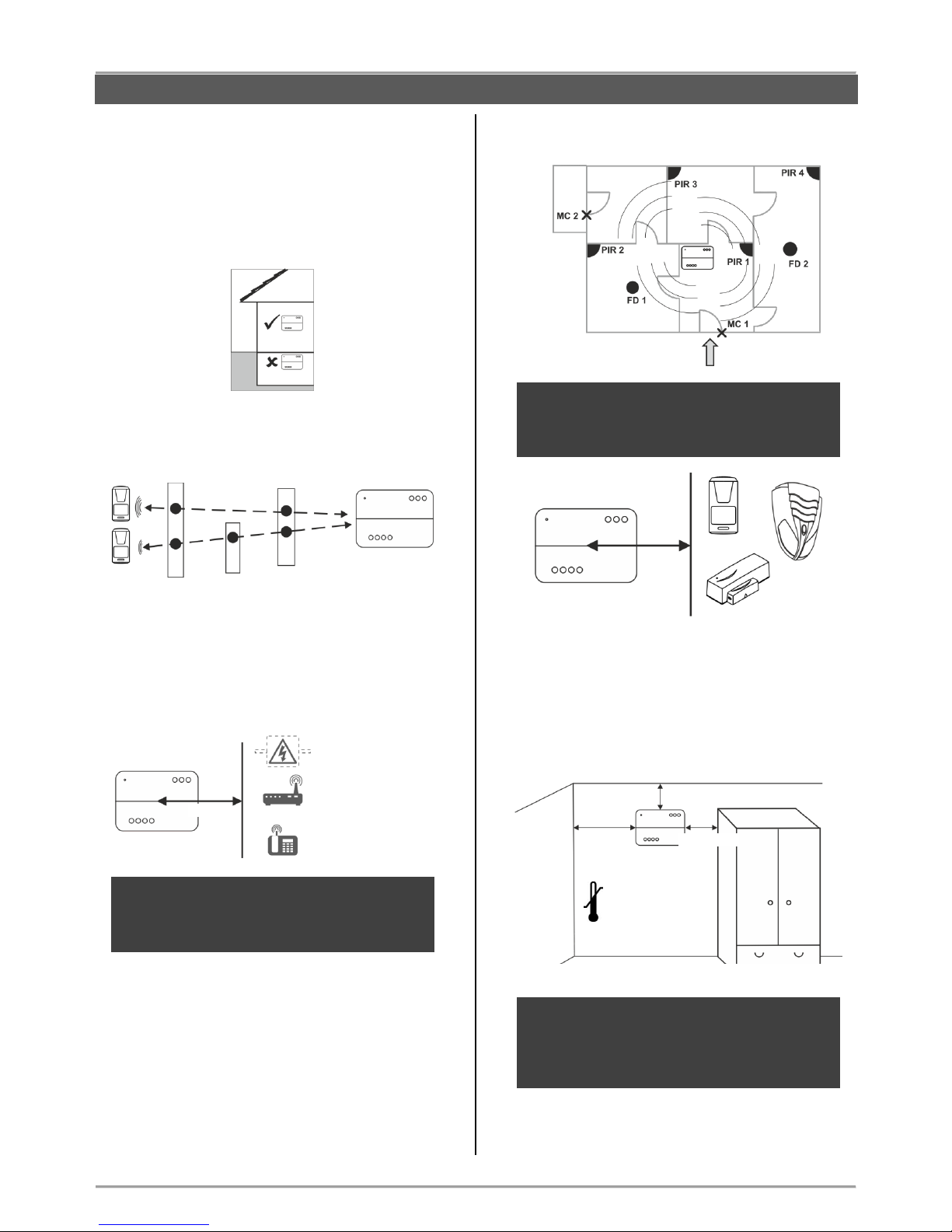
2. Planning Your Wireless System
In order to achieve the best efficiency of your wireless
system, prior to installation plan the location of the
control panel and the wireless devices within the
premises.
The installation place of the control panel should be
in premises located above the ground level.
Reduce the number of obstacles between the
control panel and the wireless devices to obtain a
stronger signal.
The control panel should be installed in a minimum
distance of at least 2 meters far from other sources
of radio signals (Wi-Fi or Bluetooth routers, wireless
telephone stations, etc.).
ATTENTION: Do not install the panel close to
sources of strong radio fields as these can cause
interference and thus diminish the serviceability
of the system and its radio band.
The control panel should be installed approximately
within the center of the protected premises.
The minimum distance between the panel and
enrolled peripheral devices must be 1 meter to
guarantee the proper operation of the system,
including in test mode.
In case of installing the control panel in a corner,
leave the following minimum distances:
o 20 cm on the left side surface to provide a free
access to the USB interface input for
programming with ProsTE software;
o 5 сm on all other sides of the box for providing a
proper ventilation.
ATTENTION: The control panel installation
location should be dry and should not be
subjected to harsh temperature changes.
The control panel should be installed close to
grounding and telephone cables.
> 20 cm.
GENERAL INFORMATION
> 2 m
Power lines
Wi-Fi/ Bluetooth routers
Wireless telephone
stations
> 5 cm.
> 5 cm.
-10°С
40°С
Entrance
> 1 m
Page 5
BRAVO – Wireless Alarm Control Panel
5
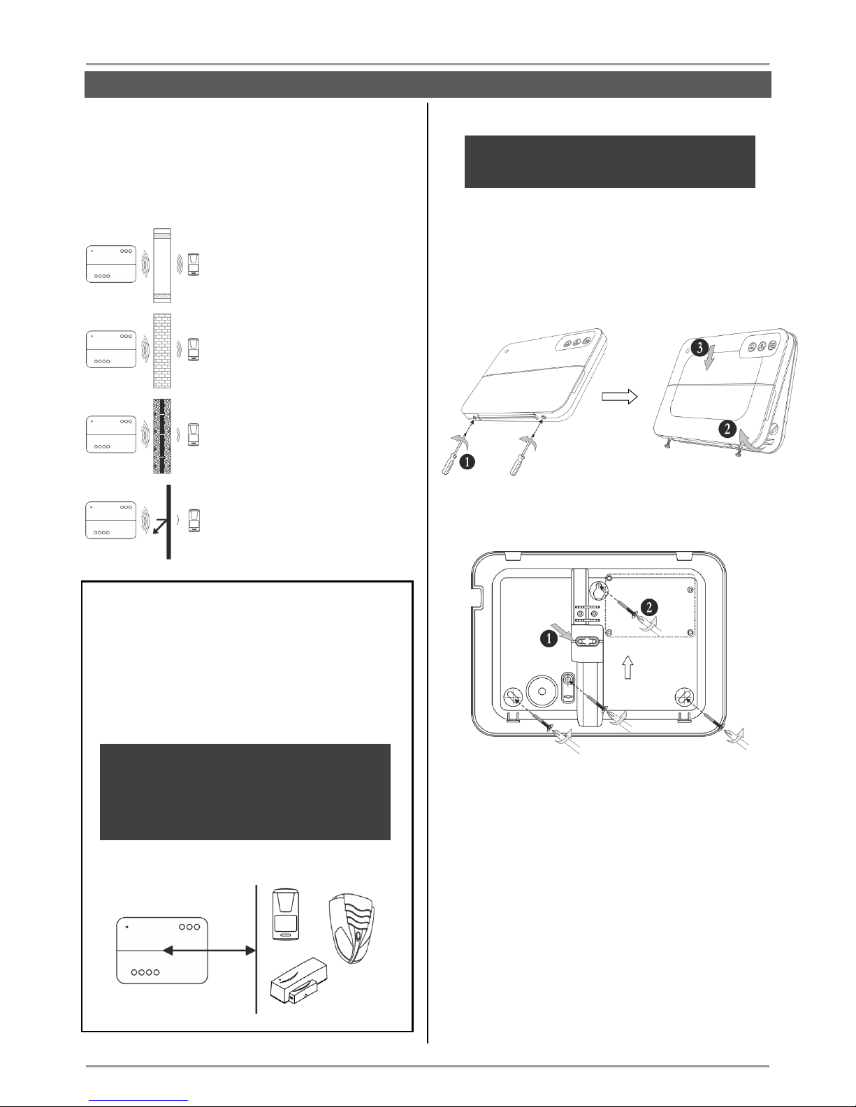
The construction and the width of the walls between
the premises also affect the radio signals
transmitted between the devices and the control
panel.
Attention: In the table below are listed approximate
values.
The quality of the radio coverage
and signal strength is reduced with
10-20% in premises with
plasterboard and wood walls.
The quality of the radio coverage
and signal strength is reduced with
30-40% in premises with brick
walls.
The quality of the radio coverage
and signal strength is reduced with
40-60% in premises with concrete
and building blocks walls.
The quality of the radio coverage
and signal strength is reduced with
80%, and sometimes with 100%
(full reflection) in premises with
metal walls or surfaces.
ATTENTION:
If you need to increase the panel’s sensitivity for
receiving the signals from the wireless devices
(because of specific conditions in the premises like
reinforced walls between the rooms, security zones
in a great distance from the panel, etc.), you can
make additional settings in the panel – move the dip
switch 8 in ON position – see section “Hardware
setting” (item 4).
In increased sensitivity for receiving signals
operation mode, the minimum distance
between the panel and enrolled peripheral
devices must be 2 meters to guarantee the
proper operation of the system, including in test
mode.
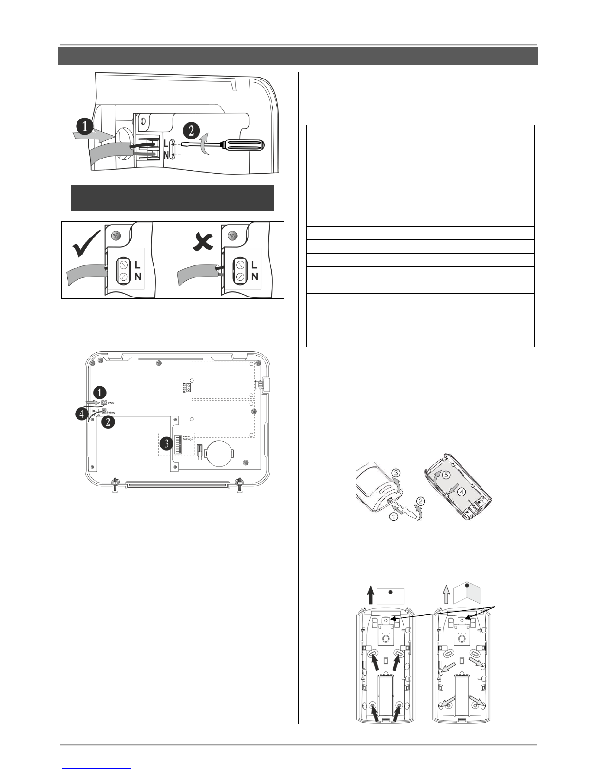
3. Basic Steps for Installation
ATTENTION: Unit must be protected by external
circuit breaker with rating 10A/B characteristics
or better.
3.1. Preparation for mounting
Undo the two screws holding the cover to the
bottom and open the panel’s enclosure.
Attention: The screws are with interrupted thread
and you do not need to undo them all. They must
stay attached to the cover.
Mount the bottom of the box as use appropriate
fixing elements according the mounting surface.
1. Break out the plastic cap from the bottom to
fix the main power cable – see the steps for
mounting of BRAVO INTR (item 3.3).
2. Fix the bottom to the mounting surface and
level it horizontally before the final mounting
with the supporting screws.
GENERAL INFORMATION
> 2 m
Page 6
BRAVO – Wireless Alarm Control Panel
6
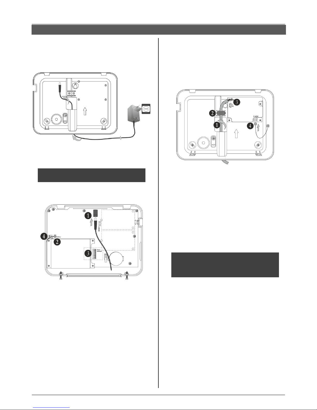
3.2. Mounting and connection of
BRAVO EXT
Run the connector of the power adapter through the
main cable channel and lead it on the internal side of
the bottom.
The cable length of the power adapter is ~1700mm,
so you have to locate the panel installation place
near a power socket.
ATTENTION: Use only the original power supply
adapter 5V/ 1A, supplied with control panel!
Prepare the panel for connecting to the mains power
230V.
1. Connect the power adaptor connector to the
input on the panel’s PCB.
2. The cable of the battery must be connected
to the “Battery” terminal.
3. Set the dip-switches position according the
system configuration – see the section
“Hardware settings” (item 4).
4. Switch on the battery – set the mini switch in
“ON” position.
Close the panel’s box following the steps in item 3.1
in a reverse order.
Plug in the power adapter in the socket and proceed
with peripheral device enrolment – see the section
“System Configuration” (item 6).
3.3. Mounting and connection of
BRAVO INTR
BRAVO INTR is a wireless alarm panel with built-in
power supply unit, which is factory mounted to the
bottom of the box.
Prepare the panel for connecting to the mains power
230V.
1. Run the mains power supply cable through
the main cable channel and lead it at the
internal side of the bottom.
2. Fix the mains power cable to the bottom
using the plastic cap and screws from the spare
parts kit.
3. Connect the mains power cable to the “L/N”
terminal as observe the polarity.
4. Assure that a special cable is connected to
“5VDC” terminal.
Note: Position the cable for 5 VDC power
supply as shown on the picture and observe
keeping this position when you close the
BRAVO INTR box!
ATTENTION: Switch on the mains power supply
(230V +10%/-15%, 50-60Hz) ONLY AFTER the
final closing of the panel’s box and switched on
battery!
The installer should strictly observe the polarity of
the electrical connection when connecting the power
cable to “L/N” terminal. The ends of the power cable
should be clearly stripped and tighten firmly to the
terminal of the power supply unit – use a plain
screwdriver to tight the screws.
INSTALLATION
Places for
mounting of
communication
modules
Slot 1
Slot 2
Page 7
BRAVO – Wireless Alarm Control Panel
7
ATTENTION: The wires should be placed tight in
the socket terminals!
Connect the cable on “5VDC” terminal to the same
terminal on the panel’s PCB.
1. Connect the cable on “5VDC” terminal of the
power supply unit to the “5VDC” terminal on the
panel’s PCB.
2. The cable of the battery must be connected
to the “Battery” terminal.
3. Set the dip-switches position according the
system configuration – see the section
“Hardware settings” (item 4).
4. Switch on the battery – set the mini switch in
“ON” position.
Close the panel’s box following the steps in item 3.1
in a reverse order.
Switch on the mains power supply and proceed with
peripheral device enrolment – see the section
“System Configuration” (item 6).
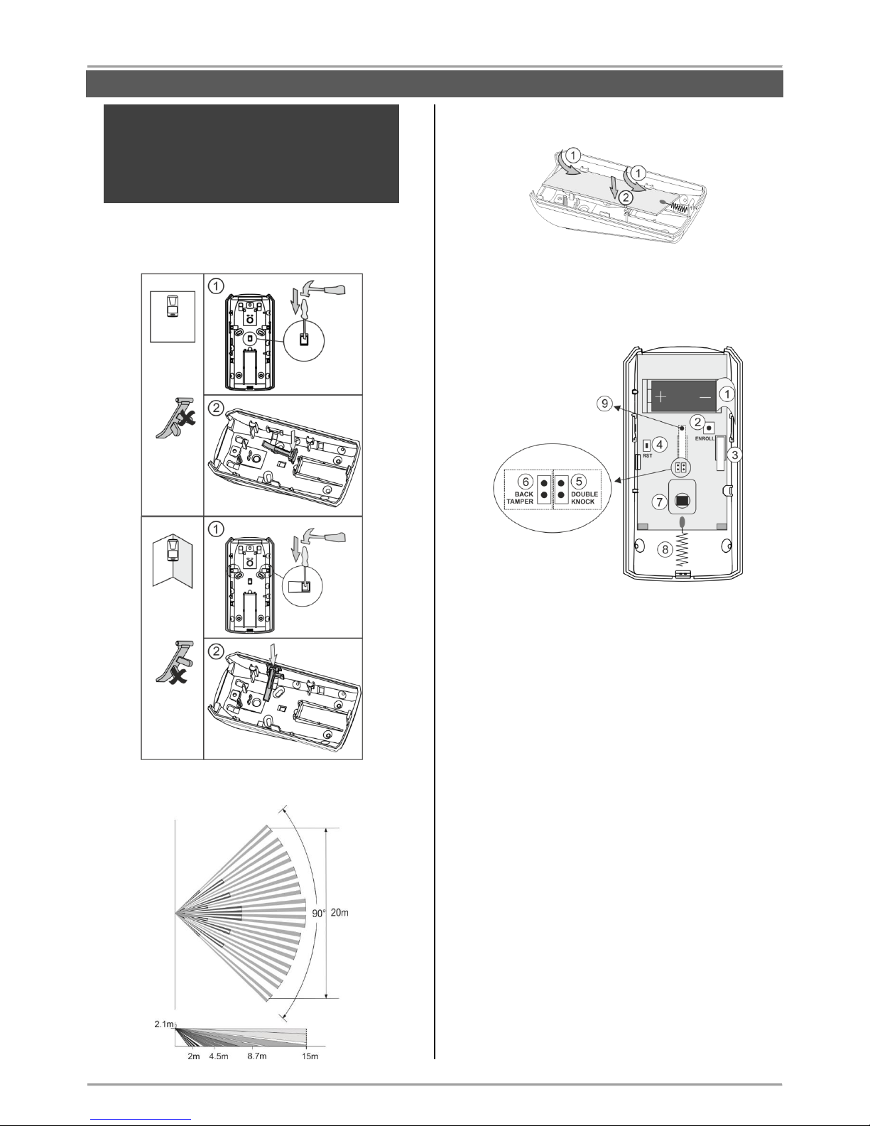
3.4. Mounting of BRAVO PIR
BRAVO PIR is a wireless passive infrared detector for
detecting of movement.
Technical Characteristics:
Certified
GRADE 2, Class II
Battery (type CR123A)
1 х 3 V/ 1500mAh
Battery life
(max. without LED*)
3 years
Operation frequency
~868 MHz
Radio distance
(open space)
Up to 400m
Working temperature
-10°C - +50°C
Storing temperature
- 40°C - +50°C
White light immunity
5 200 Lux
Walk detection speed
0.3 m/s - 3.0 m/s
Coverage angle
90°
Mounting height
1.5 - 3.6 m (2.1 m)
Number of detection zones
54
Dimensions
66 x 132 x 60 mm
Range when mounted in a corner
12 m x 12 m (90°)
Range when mounted on a wall
17 m x 15 m (110°)
* The dip-switch DSW 1 is set to OFF position (see item 4.1).
Mounting
1. Open the detector box as use small plain screwdriver
(1) - slightly press at the opening in the bottom side (2)
and then open the cover up (3).
2. Remove the detector’s PCB by pressing the clip
downward (4) and pull it out (5).
3. Mount the base of the detector’s box at the place of
installation. Use the respective opening according the
mounting location - on a wall or in a corner.
Places for
mounting of
communication
modules
Slot 1
Slot 2
Mounting on a wall
Mounting in a corner
Place for
mounting
bracket
INSTALLATION
Page 8
BRAVO – Wireless Alarm Control Panel
8
ATTENTION: When the detector is installed
on a mounting bracket, it is impossible to use
the second tamper-switch for self-protection
(on the back side of the PCB) and the
requirements of standard EN50131 Grade 2
are not covered!
Use the elements for the second tamper-switch,
according the place of installation:
Beam Coverage:
4. Mount the PCB back into the base by placing it first
on the front clips.
5. Enroll the detector to the panel as follow the steps
described at item 6.2 in “System Configuration” section.
Description of the PCB elements
1 - Protection folio for the battery; it is removed directly
before the enrolment of the detector to the panel.
2 - ENROLL Button. Use it to enroll the detector to the
panel.
3 - The first tamper-button for self-protection. Used for
signaling in case of removing the detector’s cover.
4 - RST (RESET) Button. Use it to reset the detector.
5 - DOUBLE KNOCK Jumper (“Double knock” operation
mode). Set a jumper on the terminals (on the right side)
to activate the “Double knock” operation mode.
6 - BACK TAMPER Jumper (follows the state of the
second tamper-switch for self-protection). Set a jumper
on the terminals (at the left side) to enable the operation
of the second tamper-switch.
7 - Motion sensor.
8 - Antenna.
9 - The second tamper-button for self-protection. This
tamper is activated in case of removing the detector’s
box from the installation place – it is enabled when there
is a jumper set at BACK TAMPER terminals.
Mounting
on a wall
Break the
pin
Mounting
in a
corner
Break the
pin
INSTALLATION
Page 9
BRAVO – Wireless Alarm Control Panel
9
3.5. Mounting of BRAVO PIR EXT GJD
BRAVO PIR EXT GJD is a wireless outdoor detector
suitable for different type of applications according the
requirements of the site protection.
Technical Characteristics:
Battery (type CR123A)
3 х 3 V/ 1500mAh,
Battery life
(max. without LED*)
3 years
Operation frequency
~868 MHz
Current consumption
35μА
Radio distance (open space)
Up to 400m
Operating temperature
-20°C - +55°C
White light immunity
50 kLux
Coverage area (adjustment of
the PIR part)
180° pan; 90° tilt
Coverage angle (set
according the application)
10° - 70°
Mounting height (optimal)
1.5 – 3 m
Coverage range (set
according the application)
6 – 30 m
Number of detection zones
28
Dimensions
145 x 120 x 155 mm
Protection
IP65
* The dip-switch DSW 1 is set to OFF position (see item 4.1).
Package contains:
In the packing box of outdoor detector BRAVO PIR EXT
GJD are included the following additional parts:
- 1 pc drilling template
- Wall plugs (3х31.75mm) and mounting screws
(3х31.75mm)
- 2 pcs additional sliding curtains
- 1 pc self-adhesive lens mask
- 2 pcs additional tamper feet
- 1 pc tamper cup
- 1 pcs opening tool
Mounting
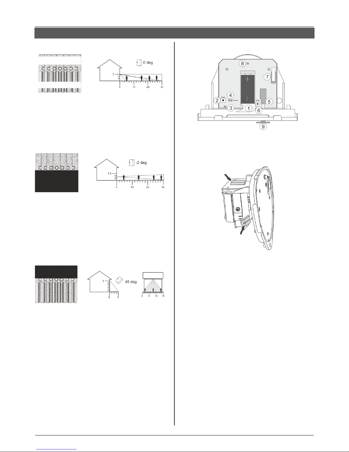
1. Remove the detector’s cover as use the opening tool
- press and turn on the tool in the shown positions on
the both sides of the detector:
2. Choose a mounting height according the
requirements for the site protection – see also item 3
further.
Use the drilling template to fix the mounting holes.
Choose a tamper foot for the back tamper according the
mounting surface – chose the one which fits good and
provides the best contact and also holds the backtamper closed.
1 – Mounting holes
2 – Back-tamper position
Mount the detector’s base as
use the wall plugs and screws
from the spare parts kit.
3. Set the position of the PIR part according the
application and the protection of the site.
Use also the showed below operating coverage
diagrams.
If it is necessary to set additionally the protecting
coverage, slide on the curtains along the PIR part. You
can use the additional curtains from the spare parts kit
to reduce the beam pattern even further.
Set the PIR part additionally fitting it to the pan and tilt.
According the application you can mask sections from
the lens so to obtain maximum efficiency in operation –
see also the examples for the beam coverage diagrams.
Beam Coverage
Beam pattern set to maximum range:
INSTALLATION
Page 10
BRAVO – Wireless Alarm Control Panel
10
Example 1 - Multi-beam optimum operation mode
The multi-beam optimum using the maximum coverage
of the detector:
- Mounting height: 3 m
- Range: up to 30 m
- Module tilt: 0°
Example 2 - “Pet Immunity Mode”
Operation diagram in “Pet Immunity Mode”:
- Mounting height: 1.5 m
- Range: up to 30 m
- Module tilt: -2°
- Use the self-adhesive lens mask as cut it and
stick it on the pointed location of the PIR
element.
Example 3 - “Curtain Mode”
Operation diagram in “Curtain Mode”:
- Mounting height: 6 m
- Range: up to 5 m
- Module tilt: 45°
- Use the self-adhesive lens mask as cut it and
stick it on the pointed location of the PIR
element.
4. Remove the protective folio of the batteries. BRAVO
PIR EXT GJD is powered from 3 batteries – one on the
main board, and two others on the second board behind
the PIR part.
5. Enroll the detector to the panel as follow the steps
described at item 6.2 in “System Configuration” section.
Description of the PCB elements
1 - Protection folio for the battery on the main board; it is
removed directly before the enrolment of the detector to
the panel. The other two batteries are located on the
second board behind the PIR part.
2 - ENROLL Button. Use it to enroll the detector to the
panel.
3 - LED for the status of the detector.
4 - Jumper Т2 (BACK TAMPER – follows the state of
the second tamper for self-protection). Set a jumper on
the terminals T2 to enable the operation of the second
tamper-switch.
5 - BACK-TAMPER for self-protection. Used for
signaling in case of removing the detector’s box from
the mounting surface – it is enabled when there is a
jumper set at T2 terminals.
6 - RESET Button. Use it to reset the detector.
7 - Tamper-button for self-protection. Used for signaling
in case of removing the detector’s cover.
8 - LED for activation of the detector. The LED is
situated on the back side of the main board. It is
operation can be disabled from the panel – see item
4.1.
9 - Back-tamper foot. In the package contents of the
detector are included 3 pcs tamper feet with different
height, as the installer has to choose the one with the
best contact to the mounting surface.
Section up to 30m
Section from 10 to 20 m
Mask that section
in “Pet Immunity
Mode”
Mask that section
in “Curtain Mode”
INSTALLATION
Page 11
BRAVO – Wireless Alarm Control Panel
11
3.6. Mounting of BRAVO Curtain
BRAVO Curtain is a wireless PIR combined with a
microwave detector for installations requiring “curtain”
type coverage in the protected site.
The PIR and MW parts are operating in AND function.
Technical Characteristics:
Battery (type CR123A)
1 х 3 V/ 1500mAh
Battery life
3 years
Operation frequency
~868 MHz
Radio distance (open space)
Up to 400m
Operating temperature
-20°C - +60°C
PIR part coverage angle
90° vertical, 7.5° horizontal
MW part coverage angle
80° vertical, 32° horizontal
Max. covering range for PIR
and MW part
12m
Mounting height (optimal)
1.5 - 3m (2.1m)
Inhibition time between two
alarms
3/6 min. (programmable via
dip switch)
Dimensions
129 x 40 x 48 mm
Protection
IP54; IP65*
* When used with a special enclosure rated IP65 for outdoor
installation (sold separately).
Package contains:
In the packing box of BRAVO Curtain detector are
included the following additional parts:
- 1 piece corner mounting base
- 1 piece wall mounting base
- 1 piece small plain screwdriver
- 2x10mm fixing screws cross slot for back box
- 1x13mm screw for fixing the front cover
- 1 piece protective plastic cap
Mounting
1. Remove the detector’s cover and take out the PCB
board. Under the board you will find the power battery
with factory mounted connector.
2. Choose a mounting height according the
requirements for the site protection.
Use the wall or corner mounting base according the
place of installation.
Mount over the base the detector’s back box using the
2x10mm screws.
3. Set the dip switches according the installation – see
position 1 at the PCB elements description.
4. On the back side of the PCB, connect the battery
connector to the terminal to power on the detector. Wait
about 30 sec for the initial initialization to complete – the
three LEDs stop chasing lighting.
5. Enroll the detector to the panel as follow the steps
described at item 6.2 in “System Configuration” section.
6. Place the PCB back to the back box as fitting it under
the side pins (1). Place the front cover on place (2) and
fix it to the bottom back box with the screw (3). Place
the plastic cap over it (4).
7. Test the detector for proper operation.
Special (Self) Test Mode
BRAVO Curtain has a special test mode for operation.
To enter the test mode, switch the dip-switch 4 on
detector’s PCB in ON position. While in test mode, the
detector will send signal to the Bravo panel every time
it detects movement. In order to turn off the Test
mode, turn dip-switch 4 OFF.
Note: The detector will stay in Test mode for
another 3 minutes after you have turned dipswitch 4 in OFF position.
Wall
mounting
base
Corner
mounting
base
Places for
fixing the
back box
INSTALLATION
Page 12

BRAVO – Wireless Alarm Control Panel
12
Beam Coverage:
Side View
Top View
Example 1 – Wall Protection
Install at about 2.1m. It can be installed also in upper
floors at about 2.1m referring to an horizontal ground
larger than 1.5m (for example balcony, ledge. Be sure
no obstacles prevent its detection (gutter pipe, shutter).
Example 2 – Shutter Protection
Install on shutter at a 2.1m height from ground.
Description of the PCB elements
The elements of PCB of BRAVO Curtain are situated
onto its both sides.
1 - Dip-switches for special functions:
No
Description
Default
1
Battery low indication:
OFF – No LED indication;
ON – The yellow LED will flash on every 2
sec, if the battery is low
OFF
2
Setting the time period between two alarm
signals:
OFF – 3 minutes*; ON – 6 minutes*
ON
3
Alarm indication:
OFF – No LED indication; ON – The red
LED is lighting on in case of alarm event
OFF
4
Test mode:
OFF – Exiting from test mode is 3 minutes
after switching off
ON – The detector sends signals to the
panel every time when detects movement.
OFF
* When the detector detects motion it would enter in a safe mode for
3/6 minutes (according the settings), as for this time period it will not
be able to generate another alarm signal, in order to save the battery.
2 - Tamper switch
3 - LED Indication:
LED
Mode
Description
Red
Test
Lights on detecting movement.
Stand-by/
Alarm
Lights on in movement when the dipswitch 3 is ON.
Yellow
Test
Lights on MW part activated.
Stand-by
Lights on if battery is low when the dipswitch 1 is ON.
Green
Test
Lights on PIR part activated.
4 - MW and PIR Range adjustment.
5 - PIR motion sensor.
6 - RESET Button. Use it to reset the detector.
7 - ENROLL Button. Use it to enroll the detector to
BRAVO panel.
8 - Connector for the battery.
9 - Not used.
10 - Antenna.
INSTALLATION
Front
Back
Use the small
plain screw
driver from the
kit to turn
ON/OFF the
dip-switches.
Page 13

BRAVO – Wireless Alarm Control Panel
13
3.7 Mounting of BRAVO MC
BRAVO MC is a wireless magnetic contact for detection
of door or window opening. BRAVO MC has a wired
zone input for connecting of wired magnetic contact or
rolling shutter detector.
Technical Characteristics:
Certified
GRADE 2, Class II
Battery (CR123A type)
1 х 3 V/ 1500mAh,
Battery life
(max. without LED*)
3 years**
Operation frequency
~868 MHz
Radio distance
(open space)
Up to 400m
Working temperature
-10°C - +50°C
Storing temperature
- 40°C - +50°C
Operation distance
25-30mm
Wired zone input
1
Dimensions
93 x 31 x 27 mm
* The dip-switch DSW 1 is set to OFF position (see item 4.1).
** When a wired magnetic contact or a rolling shutter detector is
connected to the BRAVO MC wired zone, the battery life is reduced if
the frequency of using is increased.
Mounting
1. Remove the bases of BRAVO MC and the magnet.
2. Mount the bases on the place of installation, as pay
attention to the position of the magnet in relation to the
BRAVO MC body – see the picture below.
Note: To use the wired zone input you have to
drill an additional hole for the cables.
ATTENTION: Remove the plastic cover from the
base to ensure the double action of tamper
button for self-protection.
3. Enroll the detector to the panel as follow the steps
described at item 6.2 in “System Configuration” section.
4. Mount back the magnet and BRAVO MC to their
bases.
ATTENTION: Use the plastic pads when
installing the magnet on metal surfaces. The
pads will protect the magnet field from a “shortcircuit”.
Description of the PCB elements
1 - Protection folio for the battery; it is removed directly
before the enrolment of the detector to the panel.
2 - Tamper button for self-protection (with a spring).
3 - ENROLL Button. Use it to enroll the detector to the
panel.
4 - RST (RESET) Button. Use it to reset the detector.
5 - Terminal “Wire Zone”. It is used for connection of
wired magnetic contact or rolling shutter detector.
6 - “Pulse” Jumper. Set a jumper in case a rolling
shutter detector is connected to “Wire Zone” terminal,
as the “WireZ” jumper should be set too – See Example
1.
7 - Jumper “WireZ”. Set a jumper in case a wired
magnetic contact is connected to “Wire Zone” terminal –
See Example 2.
8 - Antenna.
Plastic
cover
INSTALLATION
Page 14

BRAVO – Wireless Alarm Control Panel
14
Example 1 – Connecting a rolling shutter detector
- Set “WireZ” jumper.
- Set “Pulse” jumper.
- Connect the rolling shutter detector to “Wire
Zone” terminal. Attention: The length of the
connection wires must be up to 5 m.
Working Operation:
In case a rolling shutter detector is connected to “Wire
Zone” terminal, BRAVO MC will follow its activation and
will alert the panel when the system is armed. If at least
5 pulses from the detector are realized for 10 seconds
the detector will send a signal for an open zone. The
next signal for an open zone will be send after 30
seconds.
Example 2 – Connecting a wired magnetic contact
- Set “WireZ” jumper.
- Connect the wired magnetic contact to “Wire
Zone” terminal. Attention: The length of the
connection wires must be up to 5 m.
Working Operation:
In case a wired magnetic contact is connected to “Wire
Zone” terminal, BRAVO MC will follow its activation and
will alert the panel when the system is armed. Bravo MC
will be activated only when the wired part gets triggered.
The wireless part will not activate the detector.
3.8. Mounting of BRAVO SR200
BRAVO SR200 is a wireless electrodynamic siren for
outdoor mounting.
Technical Characteristics:
Battery
3 х 3 V/ 15Ah,
CR4615 type, size D
Battery life (max. without LED)
3 years*
Operation frequency
~868 MHz
Radio distance (open space)
Up to 400m
Working temperature
-30°C - +65°C
Storing temperature
- 40°C - +65°C
Sounder volume
115dB/ 1 m
Dimensions
180 x 210 x 85 mm
* Based on normal use of the siren (e.g. 1 alarm per month with strobe
and 1 minute alarm cycle, and 8 squawks per day at an average of
25°C). If the use is more frequent or the alarm cycle is set for more
than 1 minute the battery life may be reduced.
Using optional power supply with external power supply (adapter)
12V/1A will extend the battery life.
Mounting
1. Use a small flat screwdriver to lift up and remove the
orange plastic cap. Undo the screw fixing the plastic
cover to the base. Lift up the siren cover and remove it.
2. Remove the light pipe, undo the screws and remove
one by one the metal and the plastic covers protecting
the battery and the electronic parts.
3. Use the drilling template on the back side of the
packing box to mark and drill the holes for installation.
INSTALLATION
Page 15

BRAVO – Wireless Alarm Control Panel
15
4. Mount the siren base as first fit the screw for the main
installation hole, then level the siren, and at the end fix
the supporting screws on the both sides.
5. Set the tamper position as use the screw on it –
regulate the position so that the screw end to contact
with the installation surface, and the contact plate to be
pressed when the cover of the siren is closed (the plate
must be horizontal and when pressed with siren cover
to close the tamper button under it – a click is heard).
6. Enroll the siren to the panel configuration as follow
the steps described at item 6.5 in “System
Configuration” section.
Description of the PCB elements
1 - Terminal for connecting the battery.
2 - LED for siren status.
3 - LED signalization in Alarm mode.
4 - Terminals SPK (SPEAKER) and TAMPER for
connecting the sounder and tamper-switch wires.
5 - ENROLL Button. Use it to enroll the siren to the
panel.
6 - RST (RESET) Button. Use it to reset the detector.
7 - Terminals +12VDC and GND for optional power
supply with adapter 12VDC/ 1A – see also item 10.4.
8 - Antenna.
3.9. Mounting of BRAVO SR300
BRAVO SR300 is a wireless piezo siren for outdoor
mounting. The siren is available in two variant according
the type of the used batteries: BRAVO SR300 AKL and
BRAVО SR300 LIT.
Technical Specifications:
Certified:
- BRAVO SR300 ALK
- BRAVO SR300 LIT
GRADE 2, Class II
GRADE 2, Class IV
Battery:
- BRAVO SR300 ALK
- BRAVO SR300 LIT
4х1.5V, alkaline, LR14
2х3V or 4x3V, Li-MnO
2
Battery life (max. without
LED)
3 years*
Battery low voltage signal
sent:
- BRAVO SR300 ALK
- BRAVO SR300 LIT
At value <5.1VDC
At value <5.5VDC
Operation frequency
~868 MHz
Radio distance (open space)
Up to 400m
Working temperature:
- BRAVO SR300 ALK
- BRAVO SR300 LIT
-10°C - +40°C
-25°C - +60°C
Sounder volume
110dB/ 1 m
Dimensions
310 x 230 x 60 mm
* Based on normal use of the siren (e.g. 1 alarm per month with strobe
and 1 minute alarm cycle, and 8 squawks per day at an average of
25°C). If the use is more frequent or the alarm cycle is set for more
than 1 minute the battery life may be reduced.
Using optional power supply with adapter 12V/1A will extend the
battery life.
Mounting
1. Lift up the cover and remove it from the base. Undo
the screws and remove one-by-one the metal and the
plastic covers.
2. Use the drilling template on the back side of the
packing box to mark and drill the holes for installation.
INSTALLATION
Page 16

BRAVO – Wireless Alarm Control Panel
16
3. Mount the siren’s base as first fit the screw for the
main installation hole, then level the siren, and at the
end fix the supporting screws on the both sides.
4. Set the tamper position as use the screw on it regulate the position so that the screw end to contact
with the installation surface, and the contact plate to be
pressed when the cover of the siren is closed (the plate
must be horizontal and when pressed with siren cover
to close the tamper button under it - a click is heard).
5. Enroll the siren to the panel as follow the steps
described at item 6.5 in “System Configuration” section.
Description of the PCB elements
1 - Terminal for connecting the battery.
2 - LED for siren status.
3 - LED signalization in Alarm mode; Optional LED
signalization in standby mode (“chasing LEDs” type).
4 - Terminals SPK (SPEAKER) and TAMPER for
connecting the sounder and tamper button wires.
5 - ENROLL button. Use it to enroll the siren to the
panel.
6 - RESET Button. Use it to reset the detector.
7 - Terminals +12VDC and GND for optional power
supply with adapter 12VDC/ 1A – see also item 10.4.
8 - LED Terminals. Set a jumper to switch on the
optional “chasing LEDs” signalization. Attention: This
functionality is active only when the siren is powered up
with external adapter 12VDC/ 1A.
3.10. Mounting of BRAVO FL
BRAVO FL is a wireless flood detector.
Technical Characteristics:
Battery (CR123A type)
1 х 3 V/ 1500mAh,
Battery life
(max. without LED*)
3 years
Operation frequency
~868 MHz
Radio distance
(open space)
Up to 400m
Working temperature
-10°C - +50°C
Storing temperature
- 40°C - +50°C
Dimensions:
- body
- flood sensor
93 x 31 x 27 mm
64 х 19 х 13 mm
Connection wires
2х0,35mm, white,
2 meters
* The dip-switch DSW 1 is set to OFF position (see item 4.1).
Mounting
1. BRAVO FL is prepared for direct mounting at the
place of the installation. The main body and the flood
sensor are connected with wires 2 meters long.
2. Remove the base of BRAVO FL and prepare it for
mounting at the place of installation.
Note: The base of the detector can be mounted also
with double-sided mounting tape at the place of
installation.
INSTALLATION
Main body
Flood sensor
Connecting
wires
Page 17

BRAVO – Wireless Alarm Control Panel
17
3. Mount the flood sensor at max. 5 mm distance from
the floor of the protected room, and the main body
above is at higher position – up to 2 meters.
ATTENTION: Do not cut and change the length
of the connecting wires!
4. Enroll the detector to the panel as follow the steps
described at item 6.2 in “System Configuration” section.
Note: You can enroll BRAVO FL to every
position (zone number) from 3 to 16, as the “24hour security zone” zone type is set
automatically.
Description of the PCB elements
1 - Protection folio for the battery; it is removed directly
before the enrolment of the detector to the panel.
2 - ENROLL Button. Use it to enroll the detector to the
panel.
3 - RST (RESET) Button. Use it to reset the detector.
4 - Terminals for wired water (flood) zone – 2 meters
long wires are factory connected.
5 - Antenna.
3.11. Mounting of BRAVO FD
BRAVO FD is a wireless combined fire alarm detector
with optical-smoke and heat (rate-of-rise) parts.
Technical Characteristics:
Battery (CR123A type)
2 х 3 V/ 1500mAh,
Battery life
(max. without LED*)
3 years
Operation frequency
~868 MHz
Radio distance
(open space)
Up to 400m
Working temperature
-10°C - +50°C
Storing temperature
- 40°C - +50°C
Mounting height
Up to 16m
Protected area
Up to 120m
2
Dimensions
(including base)
103х56mm
Sensitivity
Rate-of-rise 10ºC/ min
(max 60ºC)
Class for the heat part,
according EN54-5
A1R
* The dip-switch DSW 1 is set to OFF position (see item 4.1).
Mounting
1. Remove the detector from the base as rotate both
parts opposite to each other – the base clockwise and
the detector counter clockwise.
2. Mount the base at the place of installation.
ATTENTION: Avoid placing the detector close to
the following sources of interference:
- heated surfaces;
- direct air flows from chimneys, windows, fans
and sources of evaporation
- smoke, ash and other contaminators.
2 m
Max.
5 mm
INSTALLATION
Page 18

BRAVO – Wireless Alarm Control Panel
18
3. Enroll the detector to the panel as follow the steps
described at item 6.2 in “System Configuration” section.
Note: You can enroll BRAVO FD to every
position (zone number) from 3 to 16, as the “24fire zone” zone type is set automatically.
4. Mount the detector back to the base – locate the
marker on the outer side of the detector’s body to align
with the short pin on the outer side of the base. Then
rotate the detector clockwise until the marker aligns with
the long pin on the outer side of the base.
Description of the PCB elements
1 - Protection folio for the batteries; it is removed
directly before the enrolment of the detector to the
panel.
2 - ENROLL Button. Use it to enroll the detector to the
panel.
3 - RST (RESET) Button. Use it to reset the detector.
4 - LED for the current status of the detector
5 - Tamper button for self-protection.
3.12. BRAVO key fobs
BRAVO key fobs series includes two-way and one-way
communication key fobs with variety of buttons suitable
for different applications.
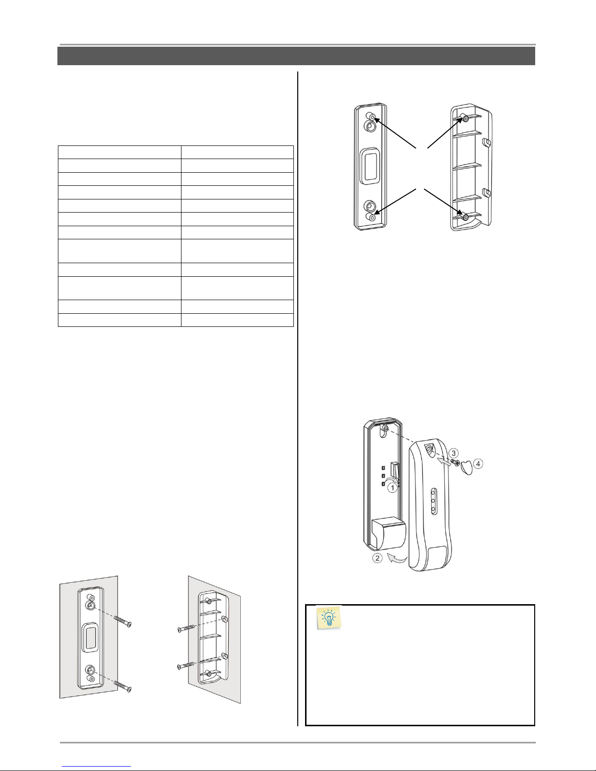
3.12.1 BRAVO RC
BRAVO RC is a two-way communication key fob with
following functionalities:
- Arming and Disarming of BRAVO system;
- Sending of additional commands to the panel,
programmable via ProsTE software;
- Information for the system status;
- Information for current alarm events via LED and
sound signalization.
Technical Characteristics:
Certified
GRADE 2, Class II
Battery (CR2450 type)
1 х 3 V/ 600 mAh,
Battery life
3 years
Operation frequency
~868 Mhz
Radio distance (open space)
Up to 200m
Working temperature
-10°C - +50°C
Storing temperature
- 40°C - +50°C
Dimensions
32х65х16mm
Switching on the battery
1. Remove the back cover of the key fob as undo the
two screws:
2. Remove the protecting folio:
3. Close the cover of the remote control.
4. Enroll the key fob to the panel as follow the steps
described at item 6.3 in “System Configuration” section.
ATTENTION: The two-way communication key
fob can be enrolled and to operate with only one
BRAVO panel.
Note: You can find detailed information for operation
with the key fobs by User in items 8 and 9 of this
manual.
The sequence for replacing the battery of a key fob is
described in item 10.2.
Mounting
holes
INSTALLATION
Page 19

BRAVO – Wireless Alarm Control Panel
19
Specialized LED indication of BRAVO RC
The button (Info) has different LED and sound
signalization when a control button is pressed:
Button
Color
Sound
Action
Green
Two signals
Full Arming
Green
One signal
According the
programmed for
the button*
Green
Three signals
Disarming
Everyone
Yellow
Long signal
Battery low of the
remote control**
Red
Long signal
No communication
with the panel
Fast
blinking
in red
-
The key fob is not
enrolled to the
panel or it has
been reset.
* The functionality of the button is programmed via ProsTE software
as the action can be different for every one remote key-fob.
** The indication is visualized after the indication of the main action of
the pressed button and refers to the used key-fob.
By pressing the (Info) button of the key fob the user
is informed for the current system status and alarm
events:
LED
Color
Sound
Description
Green
Three signals
System is disarmed
Red
Two signals
System is armed
Red
blinking
Combined
melody
Alarm memory
(in disarming)
3.12.2 BRAVO RC-XX
BRAVO RC-XX series are one-way communication key
fobs with functionality according the model.
ATTENTION: The one-way communication
key fobs can be enrolled to two or more
BRAVO panels at the same time.
BRAVO RC-41
BRAVO RC-21
BRAVO RC-11
- Arming;
- Disarming;
- A and B are
programmable
buttons.
- Arming;
- Disarming;
- 1 programmable
button, suitable
for panic alarm
No preparation for enrollment to the BRAVO panel is
needed. See item 6.4 in “System Configuration” section.
3.13. Mounting of communication modules
BRAVO wireless panel is designed for operation with
different in functionality communication modules.
The BRAVO panel can operate with up to two
communication modules at the same time, mounted to Slot
1 and Slot 2 on the main PCB of the panel.
ATTENTION: The communication modules must
be added to the system configuration ONLY
WHEN both main power supply of the control
panel and back-up battery are SWITCHED OFF.
The communication modules must be enabled
for operation via ProsTE software or Ajax SP
web application.
The priority in operation (sending of messages for events)
is set via mini dip-switch 6 on the panel’s PCB – see also
item “4. Hardware settings”.
When the “Alternative” communication type is set (position
OFF of mini dip-switch 6), the priority for message
distribution is as follows:
Slot 1 – Main communication channel
Slot 2 – Backup communication channel
Use ProsTE software to program the modules.
Types of communication modules from BRAVO series:
Module
Functionality
Monitoring
and control
GPRS
- Sending of messages for events to
Users;
- SMS messages for events to 4
telephone numbers;
- Remote management – Arming and
Disarming;
- Remote management of zones
(bypass/ de-bypass);
- Reviewing the memory log;
- Programming of panel parameters
(Ajax SP).
MobileTTE
Ajax SP
PSTN
- Sending of messages for events to 4
phone numbers;
- Choosing of communication protocol
SIA, CID or User.
-
PSTN
VD
- Sending of messages for events to 4
phone numbers with voice messaging;
- Remote control of system (arm/disarm)
over PSTN with voice guiding.
PSTN
(“Voice
Dialer”
protocol set)
MOUT/
PGM
- MOUT Mode. Sending of messages for
events via transmitter to a monitoring
station; connecting of outdoor wired
siren with external power supply.
- PGM Mode. Remote control of home
automation devices using the PGM
outputs of the module.
MobileTTE
Ajax SP
Interface connectors
for mounting of
communication
modules
Slot 1
Slot 2
INSTALLATION
Page 20

BRAVO – Wireless Alarm Control Panel
20
3.13.1. BRAVO TTE GPRS Module
BRAVO TTE GPRS communication module is
GRADE_2, Class II, SP2 (SMS), SP5 (GPRS) certified.
Mounting
1. Remove the cover of the panel – see item 3.1.
Switch off the main and backup power supply. Mount
the antenna in the opening of the main panel’s PCB (1,
2), then run the antenna cable around the support pins
on the PCB (3), mount the BRAVO TTE GPRS module
as fix it with screws to the main panel’s PCB. Connect
the antenna cable to the module’s connector.
2. Disable the PIN check option of the SIM card!
Place the SIM card into the SIM holder.
3. Switch on the main and backup power supply and
close the cover of the box.
4. Use the ProsTE software to enable the module for
operation and to set additional parameters if
needed.
Description of the PCB elements
1 - An interface connector for coupling with the panel’s
PCB (on the back side of the module PCB).
2 - Tx LED – Blinks at transmitting signals for events.
Lights on permanently for a lost connection with the
server.
3 – LED indication for the module status:
Color
Description
Red
(light on)
Problem with the SIM card; problem with the
GPRS channel; no communication with server.
Orange
(blinking)
The module is sending messages via back-up
channel.
Green
(blinking)
The module is in normal operation mode (the
connection with the server is stable and the
transmitting of messages is successful).
4 - LEDs for radio signal strength:
- All OFF: No signal.
- 1 LED lighting: Low signal.
- 2 LEDs lighting: Good signal.
- 3 LEDs lighting: Very good signal.
5 - Antenna connector.
6 - Mounting holes.
7 - Holder for the SIM card.
3.13.2. BRAVO MOUT Module
Mounting
1. Remove the cover of the panel – see item 3.1. Switch
off the main and backup power supply.
Mount BRAVO MOUT module to Slot 1 or Slot 2 on the
panel’s PCB.
2. Fix the module with screws to the panel’s PCB.
3. Connect the outputs of the module according the
application of the module.
ATTENTION: The functionality of the outputs can be set
in one of the following operation modes using ProsTE
software:
- MOUT – Transmitting signals to radio transmitter or
connecting of wired siren (see Examples 1 and 2).
- PGM – Programmable outputs OC, 100mA (see
Example 3).
4. Switch on the main and backup power supply and
close the cover of the box.
Description of the PCB elements
1 - An interface connector for coupling with the panel’s
PCB (on the back side of the module PCB).
2 - Mounting holes.
3 - Terminal row:
Output
MOUT Mode
PGM Mode
On / P1
Event “Arm / Disarm”.
OC, 100mA
A / P2
Event “Burglary Alarm”.
OC, 100mA
T / P3
Event “Tamper / Lost
device”.
OC, 100mA
P / P4
Event “Panic Alarm”.
OC, 100mA
F / P5
Event “Fire Alarm”.
OC, 100mA
S / P6
Event “Siren” – repeats
the alarm cycle of a
connected wired siren
(the silent alarms do not
affect at this output).
OC, 100mA
SirTmp
Jumper for disabling the
signals from a wired siren
connected to the module.
-
GND
Common ground.
Common ground.
4 - LED indication for the module status:
Color
Description
Yellow
Power-up initialization mode or resetting.
Red
No communication with the panel.
Green
The module is in normal operation mode.
5 - Jumper SirTmp (see the connection diagram
between BRAVO MOUT and wired siren in Application
Example 2).
INSTALLATION
Use the
two screws
for plastic
Use the
screw for
metal
Use the
two screws
for plastic
Use the
screw for
metal
Page 21

BRAVO – Wireless Alarm Control Panel
21
Application Example 1 (MOUT Mode)
Connection between BRAVO MOUT and radio
transmitter TP2000 for sending messages for events to
monitoring station.
Application Example 2 (MOUT Mode)
Connection diagram between BRAVO MOUT and wired
outdoor siren.
INSTALLATION
ATTENTION:
When the BRAVO MOUT module is
mounted on Slot 1 and “Alternative”
communication type is set, the panel
will send messages only through the
main channel and never through the
backup channel, regardless of that
whether the transmitted signal is
received from the monitoring station or
not.
When the BRAVO MOUT module is
mounted on Slot 2 and “Alternative”
communication type is set, the panel
will send messages first through the
main channel and in case of failure –
through the backup channel.
External power
supply unit
12V DC
Siren PCB
Compatible outdoor sirens
Note:
The jumper SirTmp must be removed in case
of connection of wired siren to BRAVO MOUT
module, for announcing of the following
technical troubles:
- Open tamper of the wired siren;
- Broken line between wired siren and BRAVO
MOUT module.
When the jumper SirTmp is set, the BRAVO
panel will not follow the status of the connected
wired siren.
Indication of BRAVO panel in case of
connection of wired siren to BRAVO MOUT
One wired siren can be connected to BRAVO
MOUT module - in programming mode and
selected “Sounder Group” the connected wired
siren is shown as device enrolled to position 16*.
* Note: The indication will be active directly after the
connection of BRAVO MOUT module to the panel’s PCB
and set MOUT operation mode.
For correct operation of the siren it is obligatory to
connect 2x680K resistors as shown on the
connection diagram.
The wired siren can be bypassed like all other
wireless devices in the system.
In case of technical trouble with the wired siren
(tamper signal or broken line between the siren and
BRAVO MOUT module) the indication in Technical
troubles review mode is:
External power
supply unit
12V DC
ATTENTION: Install the transmitter unit at distance
at least 5m from the BRAVO MOUT module to
guarantee the correct operation of the system!
Page 22

BRAVO – Wireless Alarm Control Panel
22
Application Example 3 (PGM Mode)
Use the BRAVO MOUT module for controlling a relay
module via the PGM outputs.
You can set an individual name for every one PGM
output via ProsTE software. The PGM outputs can be
controlled via user mobile interface MobileTTE.
ATTENTION: When the BRAVO MOUT module
is set to operate in PGM mode, Slot 1 and
Slot 2 of the panel will operate together, in
Communication type “All” – see item 4.1.
3.13.3. BRAVO PSTN and PSTN VD Modules
Mounting
1. Remove the cover of the panel – see item 3.1. Switch
off the main and backup power supply.
Mount BRAVO PSTN (PSTN VD) module to Slot 1 or
Slot 2 on the panel’s PCB.
2. Fix the module with screws to the panel’s PCB.
3. Connect the telephone line to the terminals Т and R,
and the telephone device to terminals T1 and R1. There
are no requirements for the polarity of the connection.
4. Switch on the main and backup power supply and
close the cover of the box.
5. Use the ProsTE software to enable the module for
operation and to set additional parameters if needed.
6. Perform communicator test as described in item 9.7.
Description of BRAVO PSTN elements
1 - An interface connector for coupling with the panel’s
PCB (on the back side of the module PCB).
2 - Mounting holes.
3 - Terminals for connecting of telephone line and
device.
4 - LED indication for the module status:
Color
Description
Red
The telephone line is missing. The module
is unable to send message for an event.
Green
The module is in normal operation mode
(the connection with the telephone line is
stable and the transmitting of messages is
successful).
Description of BRAVO PSTN VD elements
BRAVO PSTN VD communication module is GRADE 2,
Class II, SP1 (voice protocol), SP2 (digital protocol)
certified.
1 - An interface connector for coupling with the panel’s
PCB (on the back side of the module PCB).
2 - Mounting holes.
3 - Terminals for connecting of telephone line and
device.
4 - LED indication for the module status:
Color
Description
Red
The telephone line is missing. The module
is unable to send message for an event.
Green
The module is in normal operation mode
(the connection with the telephone line is
stable and the transmitting of messages is
successful).
5 - Holder with a mini SD card. The voice messages for
events are recorded to the mini SD card.
INSTALLATION
External power
supply unit
12/24VDC
Twisted
pair
cable
Use the
two screws
for plastic
Use the
screw for
metal
Use the
two screws
for plastic
Use the
screw for
metal
Page 23

BRAVO – Wireless Alarm Control Panel
23
4. Hardware Settings
4.1. Dip-switches
Use the dip-switches to set some additional settings
according the configuration and operation of the system.
Every dip-switch has two positions ON and OFF used to
set certain functionality.
Use a small suitable tool to set the position of a dipswitch.
ATTENTION: The numbers of the dip-switches
are described according their location on the
panel’s PCB.
The dip-switches order and their functionality are
described as:
No
Description
Position
OFF
ON
8
Power RF (Increased sensitivity
of the control panel)
7
Not used
-
-
6
Communication type
Altern.
All
5
Zone types
(see item 4.2)
Config.
1
Config.
2
4
Sound signalization on ARM/
DISARM
3
Clear the bypassed zones on
DISARM
2
LED Indication – panel
*
1
LED Indication - devices
- Enabled; - Disabled
* Note: When the dip-switch is set to ON position, the LED
indication of the panel is disabled when the system is armed.
The status LED will blink during the entry-exit time running.
When the system is disarmed the LED indication of the panel
is active.
All dip-switches are set in OFF position from the
manufacturer after the production.
To change the position of a dip-switch, open the
front cover and switch off the main and backup
power supply of the panel. Use a small suitable tool to
switch over the position of a dip-switch. Switch the main
and backup power supplies and close the panel.
The setting of the dip-switches does not change
after full hardware reset of the panel.
The current position of the hardware dip-switches
can be checked via the software applications
ProsTE and Ajax SP.
4.2. Type configurations of the zones
The installer can choose between two basic
configurations for the zone types with setting the
position of dip-switch 5.
The zone type description is as follow:
Entry-Exit – Provides time to arm and disarm the
site. After arming, the detector, which was triggered
off in this zone, will not sound an alarm until the
programmed EXIT TIME expires.
When the entry-exit zone is opened in armed mode
an ENTRY TIME starts running during which the
user must disarm the system. When the entry time
expires and the system is not disarmed the sounders
will alarm for burglary not authorized entry.
Follow – An alarm zone which is active only when
the site is armed. The zone operates
instantaneously. Activating the zone during entry or
exit time does not cause an alarm event.
Instant - An alarm zone which is active only when
the site is armed. The zone operates
instantaneously. Activating the zone during entry
time causes an alarm event, as during the first 30
sec only the built-in sounder (in the panel) will be
active and if the system has not been disarmed
during this period the outdoor sounder will be
activated too, and a message to a monitoring center
will be sent.
Fire – 24-hour fire zone. All wireless fire detectors
are automatically attached to this type of zone during
the enrollment. The zone operates instantaneously
when a fire detector is activated as the sounders are
activated and FIRE alarm message is sent via the
available communication channels.
24-hour security zone. All wireless flood detectors
are automatically attached to this type of zone during
the enrollment. The zone operates instantaneously
when a flood detector is activated as FLOOD alarm
message is sent via the available communication
channels.
The description of the zone configurations:
Zone No
Configuration
Type of the
Detector*
1
2
1
Entry-Exit
Instant
MC or PIR
2
Entry-Exit
Instant
MC
Follow
PIR
3-16
Instant, fire
or 24-hour
security
zone
Instant, fire
or 24-hour
security
zone
Every of the
BRAVO detectors
* Up to 1 detector can be enrolled to a zone. The type of
the detectors mentioned in the table above are suitable
for realization of Configuration 1.
HARDWARE SETTINGS
Page 24

BRAVO – Wireless Alarm Control Panel
24
4.3. Hardware reset
After hardware reset of the panel all default settings are
restored, the enrolled devices and the memory log
events are deleted.
To perform hardware reset:
1. Switch off the main and the back-up power
supply of the panel.
2. Set a jumper on the RESET terminals.
3. Switch on the main and the back-up power
supply of the panel – the zone LEDs (1-16) are
blinking in sequence in different colors –
signalization “chasing LEDs” type.
4. Remove the jumper from the RESET
terminals – the panel goes to normal operation
mode, as only the status LED is lighting on in
green.
Note: You can skip the chasing LEDs signalization test
as directly remove the jumper from RESET terminals
after switching on the mains and back-up power supply.
After the initial start-up and every resetting, the
panel goes through initialization procedure – the
status LED starts blinking for 10-15 seconds until
the system is established in normal operation
mode.
4.4. Sound signalization from the panel
Signalization
Description
Button*
Single short beep indicating the
pressing of a key.
Confirmation
Two long sound signals, indicating the
system confirmation for executed
operation.
Cancelation
A single long beep, indicating system
incorrectly executed operation.
Entry time*
Continuous beep, indicating intrusion
into an entrance zone.
Exit time*
Short beeps, indicating the system is
armed and the user is required to
leave the entrance zone. Ten seconds
before the exit time is over beep
frequency increases.
Technical
trouble*
Two short beeps at every 20 sec,
indicating a technical trouble. To stop
the signalization - press the
ATTENTION button.
Chime*
Short beeps with subsequently
increasing period, indicating intrusion
into a zone with an activated chime
option when the system is disarmed.
Arming
The dip-switch 4 is set in ON position.
One short sound signal indicating
system ARMING.
Disarming
The dip-switch 4 is set in ON position.
Two short sound signals indicating
system DISARMING.
Four short sound signals indicating
system DISARMING when there is
memory for alarm event.
* Note: The signalization can be disabled via specialized
ProsTE programming software.
HARDWARE SETTINGS
Page 25

BRAVO – Wireless Alarm Control Panel
25
5. Description of the Front Panel
5.1. Buttons
System Control
Button Programming
- Entry/ Exit for “Device enrolment” mode –
see item 6.1;
- Scrolling over the device groups in “Device
enrolment” mode;
- Entering in a special mode for disarming
the system from User via the panel’s buttons
– see item 8.3.2.
LED Indication
After entering in the “Device enrolment”
mode lights on in red.
Button Cancel
- Deleting a device in “Device enrolment”
mode - see item 7.6.
- Confirmation of digits in a special mode for
disarming the system from User via the
panel’s buttons - see item 8.3.2.
Back
Forward
Arrow Buttons
- Scrolling over zone and position numbers
in “Device enrolment” mode, for reviewing
the bypassed devices in the system, or
reviewing the alarms in zones;
- Selecting digits in a special mode for
disarming the system from User via the
panel’s buttons - see item 8.3.2.
System Status
Button Alarm Review
- Entry/ Exit for “Reviewing Alarm Events”
mode - see item 9.2.
LED Indication
In case of alarm event in the system lights
on in red. After entering the “Reviewing
Alarm Events” mode, the button is blinking.
Button Attention
- Entry/ Exit for “Reviewing Troubles” mode see item 9.1.
LED Indication
In case of a technical trouble in the system
lights on in yellow. After entering the
“Reviewing Troubles” mode, the button is
blinking.
Button Bypass
- Entry/ Exit for “Bypassing zones/ devices”
mode - see item 7.5.
LED Indication
Lights on in yellow if there are bypassed
zones/ devices in the system. After entering
the “Reviewing bypassed Zones/ Devices”
mode, the button is blinking.
BUTTONS AND INDICATION
BRAVO Panel – Front view, open cover.
Information Buttons
for System Status
Control
Buttons
LED Indication
for the System
System
Status
LED Indication for
Zones/ Devices
Device
Groups
Device
Troubles
Panel
Troubles
Page 26

BRAVO – Wireless Alarm Control Panel
26
5.2. LED Indication
System Status
Information LED for the current status of the
system:
Green
- Normal operation mode.
- The system is ready for arming.
- Blinking during searching of a free
channel.
Red
- The system is armed.
- Blinking during an alarm cycle.
Off
- The system is not ready for arming there are open instant type zones.
- No main or back-up power supply.
- The jumper RESET is not removed.
- Technical problem with the panel or with
a device.
Indicators for Device Groups
Detectors
To the group can be enrolled up to 16
devices from BRAVO PIR, MC, FD or FL
type – only 1 detector to each zone.
LED Indication
Lights on in red in case of activated detector
together with the corresponding zone
number.
In “Device enrolment” mode lights on
permanently as indication for a selected
group.
Key fob remote controls
To the group can be enrolled up to 8 devices
BRAVO RC type.
Attention: The enrolled to positions 1 and
2 key fobs become MANAGER and are
obligatory for entry in “Device
enrolment” mode – see item 6.3.
LED Indication
In “Device enrolment” mode lights on
permanently as indication for a selected
group.
Sounders
To the group can be enrolled 1 outdoor
wireless siren.
LED Indication
In “Device enrolment” mode lights on
permanently as indication for a selected
group.
Indicator for Walk Test
Walk Test Mode
Indication for entering in walk test mode –
see item 7.4 for details.
Indicators for Device Troubles
Technical trouble
Indication for:
- Activated tamper switch of a device;
- Lost device.
Battery low charge
Indication for low battery charge of a device.
LED Indication
In “Reviewing Troubles” mode the respective LED
indicator lights on in yellow and the number of the first
device with trouble is blinking and the indicator for its
type is lighting on. If there are more devices with
troubles, their numbers are lighting in yellow.
Reviewing of their type is done by the arrows.
Indicators for Panel Troubles
Tamper
Indication for activated tamper – the panel’s
box is open or the tamper plate on the
bottom is broken.
Mains power supply 230V lost
The sound signalization for mains power
supply lost can be immediate or delayed for
programmed time interval.
By default the signalization is immediate.
The time delay for the signalization can be
programmed via specialized ProsTE
software.
Battery low charge
Indication for low charge, missing or
switched off battery of the panel.
Trouble with the communication channel
Indication for trouble in the connection with
any of the used communication modules.
LED Indication
In “Reviewing Troubles” mode the respective LED
indicator lights on in yellow.
Indicators for Zones / Devices
LED Indication
Color
Mode
Enrolment
Test
Green
Free position
Successful test
Red
Enrolled device
Unsuccessful test
Yellow
Bypassed device
Open zone
Off
The position is not
used for the current
type of the device
No device enrolled
to the position
BUTTONS AND INDICATION
Page 27

BRAVO – Wireless Alarm Control Panel
27
6. Device Enrolment
The enrolment is a process of adding peripheral devices
to the system configuration.
The LED indication has the following meaning:
A device group is selected, when the LED indicator
under the respective icon lights on permanently in red.
The exit from the “Device enrolment” mode is automatic
after 10 minutes if there is no activity with the panel
(button pressed). Exit from the “Device enrolment”
mode can be done also with pressing of button
“Programming” several times.
ATTENTION: Up to 1 detector can be enrolled to a
zone.
The minimum distance between the panel and
enrolled peripheral devices must be 1 meter (in
increased sensitivity mode - 2 meters) to
guarantee the proper operation of the system,
including in test mode.
6.1. Access to the Device Enrolment mode
In case of a new system, or after realized hardware
reset, or NO MANAGER key fobs are enrolled to the
system configuration, to enter in “Device enrolment”
mode press button:
In case that there are MANAGER key fobs already
enrolled to the system configuration, to enter in
“Device enrolment” mode press in sequence:
6.2. General steps for enrolling a detector
Prepare the detector for enrolling – remove the cover
to access the detector’s PCB and the battery.
Enter in “Device enrolment” mode.
The system enters in the menu for detectors
enrolment. The LED indicator under the icon is
lighting on and the Zone 1 is blinking:
The numbers of the free zones (with no detectors
enrolled) are lighting in green, and those with already
enrolled devices – in red. The currently selected zone
number is blinking.
Use the buttons with arrows to select a number of a
free zone – the zone number is blinking in green.
Remove the protection folio from the battery – the
LED(s) of the detector is lighting in sequence in red
and green. For BRAVO Curtain – connect the battery
to the connector on the PCB (back side).
Press the ENROLL button on the detector’s PCB –
the LED(s) is blinking in red and after a short time
interval – in green. The panel confirms the
successful enrolment with a sound signal, and the
selected zone number is blinking in red.
Go to the place for installation of the detector and
make a radio test for signal strength – see item 7.1.
Close the cover of the detector and check it for
proper operation – when the detector is activated
(zone open) the respective zone number on the
panel lights on in red together with the indicator for
type of the device.
6.3. General steps for enrolling a two-way
key fob – BRAVO RC
Prepare the remote key-fob for enrollment to the
system – remove the cover and pull out the
protection folio. Close the cover and tight on the
screws.
Enter in “Device enrolment” mode.
The system enters in the menu for detectors
enrolment. Press the “Programming” button once
again to move to the menu for key fobs enrolment.
The LED indicator under the icon is lighting on and
the position 1 is blinking:
The numbers of the free positions (with no key fobs
enrolled) are lighting in green, and those with already
enrolled key fobs – in red. The currently selected
position number is blinking.
SYSTEM CONFIGURATION
The button
is blinking
Button of a
MANAGER key fob
Up to 30 sec
> 1 m
Device Groups
Position of a device
(zone number)
Page 28

BRAVO – Wireless Alarm Control Panel
28
ATTENTION: The enrolled to positions 1 and 2
key fob remote controls are called MANAGER
and are used for entry in “Device enrolment”
mode and zone walk test.
Use the buttons with arrows to select a number of a
free position – the number is blinking in green.
Press random button of the key fob – the LED
(Info) blinks in red and after a short time interval
lights on in green. The panel confirms the successful
enrolment with a sound signal, and the selected
position number is blinking in red.
After exit from the “Device enrolment” mode the key
fob is ready for operation.
6.4. General steps for enrolling a one-way
key fob – BRAVO RC-11/RC-21/RC-41
Enter in “Device enrolment” mode.
The system enters in the menu for detectors
enrolment. Press the “Programming” button once
again to move to the menu for key fobs enrolment.
The LED indicator under the icon is lighting on and
the position 1 is blinking:
The numbers of the free positions (with no key fobs
enrolled) are lighting in green, and those with already
enrolled key fobs – in red. The currently selected
position number is blinking.
Use the buttons with arrows to select a number of a
free position – the number is blinking in green.
For BRAVO RC-21 and BRAVO RC-41 press twice
quickly the “open key lock” and then press and hold
it for 3-5 seconds:
For BRAVO RC-11 use for enrollment its single
button: press it twice quickly and then press and hold
it for 3-5 sec.
The LED indication of the key fob blinks three times
in red.
The panel confirms the successful enrolment with a
sound signal, and the selected position number is
blinking in red.
By default the button of BRAVO RC, buttons “A”
and “B” of BRAVO RC-41 and the button of BRAVO
RC-11 have no functionality. The installer can program
the functionality of each button via ProsTE software.
The functionality of the buttons can be set to be different
for every of the key fobs.
6.5. General steps for enrolling an outdoor
sounder
Prepare the siren for enrolment – remove the covers
to access the PCB and the battery terminals.
Enter in “Device enrolment” mode.
The system enters in the menu for detectors
enrolment. Press the “Programming” button twice to
move to the menu for sounder enrolment. The LED
indicator under the icon is lighting on and the
position 1 is blinking:
The BRAVO panel supports operation with one outdoor
sounder, which can be enrolled to position 1.
Switch on the battery – the LED on the PCB is
lighting on in sequence in red and green.
Press the ENROLL button – the LED is blinking in
red and after a short time interval – in green. The
panel confirms the successful enrolment with a
sound signal, and the position number is blinking in
red.
Go to the place for installation of the sounder and
make a radio test for signal strength – see item 7.1.
Close the covers of the sounder and test its
operation simulating an alarm event.
By default the alarm cycle of the sounder is set to 1
minute. The installer can program other duration of
the alarm cycle (up to 3 minutes) via ProsTE
software.
Tips & Tricks...
You can scroll over the device groups also using
the arrow buttons - when reaching the last zone /
position the panel automatically moves to the next
device group.
Leave the enrolment of the used key fobs at the
end - in this way the entry in the “Device enrolment”
mode will be easier during the installation of the
other devices.
In “Device enrolment” mode the zones / positions of
the bypassed devices are lighting in yellow.
Use a double-sided mounting tape for fixing the
detectors during the initial installation - it is possible
to change the mounting place later in order to
obtain a better strength of the radio signal.
After successful enrolment to the panel, write down
the zone number on the sticker and place it on the
inner side of the detector’s enclosure.
Fill in the Object card for the protected site given at
item 11.
SYSTEM CONFIGURATION
Press twice -
fast
Press and hold
for 3-5 sec
Page 29

BRAVO – Wireless Alarm Control Panel
29
7. Test of Devices
7.1. Radio test of devices
The radio test should be performed in order to check the
signal strength on the site and the quality of the
communication between the control panel and the
wireless devices (BRAVO PIR, MC, FL, FD, SR200,
SR300, etc).
The radio test can be performed directly after the
enrolment of the device and after that during the
maintenance of the system.
To perform a radio test of a device:
Remove the cover of the device to access the PCB.
Press the ENROLL button - the LED(s) will blink
single in green. Up to 30 seconds the device will
inform for signal coverage with a new indication with
the following meaning:
- 3 blinks in green - the signal coverage is good and
there is a stable communication between the device
and the panel;
- 3 blinks in red - no signal coverage and
communication between the device and the panel;
- 3 blinks in yellow – there is a signal coverage, but
the communication between the device and the
panel is unstable. In this case it is recommended to
change the place of installation and to perform a new
radio test.
Tips & Tricks...
Perform the radio test just after the enrolment of
the device and at the place of installation, as in that
way you can choose the place with the best signal
coverage.
7.2. Key fob operation test
Perform this test to check the communication between
the panel and the key fob remote control, and also the
position to which it is enrolled.
To perform the key fob operation test:
Enter in “Device enrolment” mode.
The system enters in the menu for detectors
enrolment.
To perform the test press:
BRAVO RC - button;
BRAVO RC-21/RC-41 - or button;
BRAVO RC-11 – the single button.
The panel automatically enters in the key fobs menu
and the number of the position to which the key fob
is enrolled is blinking.
7.3. Outdoor sounder operation test
The test can be performed, if an option “Siren check” is
set to a programmable button of a key fob. When this
option is set and programmed to the panel via ProsTE
software, in every pressing of the button of the key fob,
the outdoor sounder replays with a single squawk.
7.4. Zone Walk Test
Perform this test to check the communication between
the panel and the enrolled devices to the zones.
The test can be performed only if there is a
MANAGER key fob enrolled to the system
configuration.
To perform a zone walk test enter in in “Device
enrolment” mode and then press 3 times the
“Programming” button to move to the Test Mode – the
indication for Walk Test lights on in red:
The panel enters in a walk test mode for 10 minutes.
Every pressing of a random button of the MANAGER
key fob starts a new time interval of 10 minutes.
The zone numbers with enrolled devices (PIR, MC,
FD, FL or Curtain type) are lighting on in red.
Activate a detector (open the zone) – the respective
zone number is blinking in yellow, which means that
the zone is open. The panel confirms the test with
Chime sound signal, and the outdoor sounder with a
single flash and squawk signals.
The walk test is successful if after closing of the zone
its number is lighting on in green.
The walk test is not successful if after closing of the
zone its number is lighting on in red.
The exit from the zone walk test mode is automatic after
10 minutes, if there is no pressed button of a
MANAGER key fob. The installer can exit the walk test
mode at any time with pressing the “Programming”
button.
7.5. Bypassing of Devices
Bypassing is a special mode for disabling devices
temporally from the system configuration. The panel
does not follow the current status of the bypassed
devices.
To bypass (disable) a device:
- Enter in “Device enrolment” mode.
- Use arrow buttons to select a number of device,
which you want to bypass.
- The number of the selected device on the panel is
blinking in red and the detector’s LED(s) - in yellow.
- Press the “Bypass” button.
- The number of the selected device on the panel is
blinking in yellow.
- Press the “Programming” button several times
to exit the “Device enrolment” mode.
- The “Bypass” button is lighting on in yellow, which
is an indication for bypassed devices in the system.
SYSTEM CONFIGURATION
Page 30

BRAVO – Wireless Alarm Control Panel
30
To un-bypass (enable) a device:
- Enter in “Device enrolment” mode.
- The numbers of the bypassed devices are lighting
in yellow.
- Use the arrows to select the number of a bypassed
device, which you want to enable – blinking in
yellow.
- Press the “Bypass” button.
- The number of the device on the panel is blinking in
red.
- Press the button “Programming” several times
to exit the “Device enrolment” mode.
To bypass/ un-bypass a key fob:
- Enter in “Device enrolment” mode.
- Press the button “Programming” .
- Use arrow buttons to select a number of key fob,
which you want to bypass/ un-bypass.
- Press the “Bypass” button.
- Press the button “Programming” several times
to exit the “Device enrolment” mode.
To bypass/ un-bypass an outdoor sounder:
- Enter in “Device enrolment” mode.
- Press twice the button “Programming” .
- Press the “Bypass” button.
- Press the button “Programming” to exit the
“Device enrolment” mode.
Note: If a wired siren is connected to the panel
via BRAVO MOUT module it is shown as
enrolled device to position 16. The wired siren
can be bypassed in the same way as the
wireless sounder, as selecting position 16 and
pressing the “Bypass” button.
7.6. Deleting of Devices
The deleting is a process for complete removing of a
device from the system configuration.
To delete a device:
- Enter in “Device enrolment” mode.
- Use arrow buttons to select a number of device,
which you want to delete.
- The number of the selected device on the panel is
blinking in red and detector’s LED(s) – in yellow.
- Press and hold the “Cancel” button until a
confirmation sound signal is heard*.
- The number of the zone on the panel is blinking in
green.
- Press the “Programming” button several times
to exit the “Device enrolment” mode.
* Note: The process of a device deleting may take time
up to 15 seconds if the device is missing or it had been
reset.
7.7. Resetting Detectors and Sounders
The resetting of a device is restoring of its default
factory settings. But the position to which the device has
been enrolled to the panel stays occupied. If the
occupied position is not deleted, with the next
enrollment of the same device to the panel it will be
attached automatically to this position.
To reset a detector or outdoor sounder:
- Remove the cover of the device.
- With battery on, press the “RESET” or “RST” button
for 3-5 seconds until you see 3 green blinks from the
LED(s).
7.8. Resetting Two-way Key Fobs
- Press and hold at the same time + buttons
of the key fob until the button lights on in red.
- Release buttons + .
- Press the button while is lighting on in red (the
button will lighting on in arrond 5 seconds).
- Wait the button to blink three times in green –
the key fob is reseted.
ATTENTION: Before resetting of a MANAGER
key fob it is obligatory first to delete it or
bypass it from the panel!
Tips & Tricks...
The zone walk test is performed to all detectors in
the system including the bypassed ones.
Enter in zone walk test mode and start system
testing from the near to control panel devices.
Press a random button of the key fob every time
after a successful test to prolong the time of the
test.
If you are not familiar with the system configuration
you can check the detector number (zone number),
as enter in “Device enrolment” mode – the number
of a selected device is blinking in red on the panel,
and the device LED(s) – in yellow.
It is recommended to remove the batteries of all
bypassed, deleted and reset devices if you are
planning not to use them for a long time.
IT IS OBLIGATORY TO REMOVE THE
BATTERIES OF ALL DEVICES if the BRAVO
system will not be in use for a long time and the
main and back-up power supplies of the panel
are switched off.
SYSTEM CONFIGURATION
Page 31

BRAVO – Wireless Alarm Control Panel
31
8. Arm and Disarm Management
IMPORTANT: To arm/ disarm and to check the status
of your BRAVO panel via smart phone or tablet you
should install the mobile application MobileTTE, which
is available for download and installation from here:
8.1. Full Arming Mode
Full arming mode means all zones are secured except
the bypassed ones.
The arming is performed with a key fobs, mobile
application Mobile TTE or user web interface Ajax SP.
To arm the system, press button of the key fob.
An exit time starts running during which the user must
leave the premises.
ATTENTION: The arming can be instant without
exit time for leaving the premises. This depends
on the set default type configuration of the zones
- see the settings of dip-switch 6 in the object
card, item 11!
8.2. Stay Arming Mode
Stay arming mode means the user is allowed to stay at
certain zones - this is a partial arming of the system.
The zones which will stay disarmed in this mode are
programmed via ProsTE software.
To arm the system, press , A or B button of the key
fob. An exit time starts running during which the user
must leave the premises.
ATTENTION: The programmable buttons must
be enabled for operation with setting the “Stay
ARM” option via ProsTE software - check the
setting in the object card, item 11!
8.3. Disarming
Going in the entrance zone the user must disarm the
system during the entry time running. The user can
disarm the system with a key fobs, mobile application
MobileTTE, user web interface Ajax SP or via panels’
buttons.
8.3.1. Disarming via key fob
To disarm the system, press button of the key fob.
8.3.2. Disarming via panel buttons
Attention: This functionality is available only if a
special disarm code is set via ProsTE software!
Use the arrow buttons to enter digits from 1 to 9,
and 10 for 0.
Example
For illustration of the specialized code entering we will
present entering of Disarm code 3208:
The system is in Full or Stay ARM mode.
Press button
Zone 1 is blinking in yellow
Press the “Forward” arrow button to digit 3
Zone 3 is blinking in yellow
Confirm – Press and hold the button for 2-3 sec.
Zone 3 will light for short in green – the digit is
confirmed
Press the “Back” arrow button back to digit 2
Zone 2 is blinking in yellow
Confirm – Press and hold the button for 2-3 sec.
Zone 2 will light for short in green – the digit is
confirmed
Press the “Forward” arrow button to digit 10
(10 is used for entering of 0)
Zone 10 is blinking in yellow
Confirm – Press and hold the button for 2-3 sec.
Zone 10 will light for short in green – the digit is
confirmed
Press the “Back” arrow button back to digit 8
Zone 8 is blinking in yellow
Confirm – Press and hold the button for 2-3 sec.
Zone 8 will light for short in green – the digit is
confirmed
ATTENTION: Entering of the specialized disarm
code can be canceled at any time by pressing
the “Programming” button – that will reject the
entered digits and the user can restart the code
performing.
USER INSTRUCTIONS
Page 32

BRAVO – Wireless Alarm Control Panel
32
9. Operation with the System
9.1. Reviewing of Alarm events
Button
lights on permanently in red.
Press the button to review the current alarm events.
The zone number with the newest (last in the time)
alarm is blinking and the group device indicator is
lighting on. The other zone numbers with active alarms
are lighting on. Use the arrow buttons to review the
order of the alarms as:
- arrow for scrolling to the before last alarm;
- arrow for scrolling to the first alarm. While the
zone number is selected the LED of the device enrolled
to it is blinking in yellow.
9.2. Clearing of Alarm events
The indication for the alarms will stay active until the
next arming, but user can cleared it also manually.
To clear manually the alarms, press in sequence:
To exit from the Reviewing Alarms Mode press the
“Memory” button once again. The exit is automatic after
3 minutes if there is no pressed button.
9.3. Reviewing Troubles Mode
Button
lights on permanently in yellow.
The panel performs two short sound signals at every
20 seconds.
Press the “Attention” button to review the current
troubles indicated from devices and/ or the panel. For
detailed description of the indicators see also items 5.1
and 5.2.
To exit from the Reviewing Troubles Mode press the
“Attention” button once again. The exit is automatic after
3 minutes if there is no pressed button.
After exit from the Reviewing Troubles Mode the sound
signalization will stop. LED indication will remain active
until restoring of the current troubles.
9.4. Reviewing of Bypassed Devices
Button
lights on permanently in yellow.
Press the button to review the bypassed devices. The
zone number of the first bypassed device is blinking and
the group device indicator is showing its type. The LED
of the selected device is blinking in yellow. Use the
arrow buttons to review the other bypassed devices.
Press the button to review if there are bypassed
devices from other group types.
To exit from the Reviewing Bypassed Devices press the
“Bypass” button once again. The exit is automatic after
3 minutes if there is no pressed button.
9.5. Erasing the Log Memory
ATTENTION: The full list of the last 300 memory
events can be viewed via ProsTE software,
Mobile TTE and Ajax SP web application.
To erase the log memory:
Enter in “Device enrolment” mode.
Use the arrows to select a free zone or position – it is
blinking in green.
Press and hold at the same time buttons + .
The panel will confirm the erasing with a sound
signal.
9.6. Changing Signal Strength of a Key Fob
This functionality allows the user to increase/ decrease
the strength of the emitted signal of the key fobs. It is
available only with BRAVO RC two-way remote control.
To increase the signal strength, press at the same
time the buttons + of the key fob.
To decrease the signal strength, press at the same
time the buttons + of the key fob.
The
button is
blinking
Button of a MANAGER
key fob
USER INSTRUCTIONS
Page 33

BRAVO – Wireless Alarm Control Panel
33
9.7. PSTN Communicator Test
This is a functional test for correct operation of BRAVO
PSTN or BRAVO PSTN VD mounted on Slot 1 or 2 of
the panel.
The test is performed with a few steps which are
repeated for every of the recorded phone numbers.
To start the functional test of the PSTN communicator,
choose in sequence:
The panel starts the test for the first recorded phone
number following the steps:
1 – Dialing the phone number
2 – Waiting for “handshake” signal from the monitoring
station
3 – Tansmitting signals to the monitoring station
4 – Waiting for confirmation from the monitoring station,
“kissoff” signal.
The step which is currently in performance is ligthing in
yellow, and the steps which are about to perform are
ligthing on in red, the successful test steps are ligthing
on green.
The test is successful when all of the steps are ligthing
on in green and the communicator starts testing the
transmitting througth the next recorded phone number.
The LED indication during testing of all (4) recorded
phone numbers is as follows:
- When testing Phone number 1 are ligthing in
sequence LEDs from 1 to 4.
- When testing Phone number 2 are ligthing in
sequence LEDs from 5 to 8.
- When testing Phone number 3 are ligthing in
sequence LEDs from 9 to 12.
- When testing Phone number 4 are ligthing in
sequence LEDs from 13 to 16.
The exit from the PSTN test mode is automatic after
finishing of the last test.
The test can be canceled at any time by pressing the
CANCEL button.
9.8. Test of the Panel’s LED Indication
This is a test for the LED indication of the panel for the
zones and events.
1. Enter in Zone Test Mode (Walk Test):
2. Press the button. All LEDs start lighting
in sequence in the supported colors. When the
test is complete the panel goes back to the
Zone Walk Test.
9.9. Automatic Diagnostic (Test) of
Peripheral Devices
All BRAVO peripheral devices operate on algorithm,
allowing performance of a periodic automatic selfdiagnostic test for operability. In case of trouble in
device operation, its LED* will light on permanently in
red. In this case the User of the system has to take off
the cover of the device and to remove the battery.
The service repair of devices with trouble in operation
found during self-diagnostic test must be performed only
in a service department of the manufacturer and
authorized personnel. In this case the User has to ask
for support the installer of the system or the service
provider authorized from the manufacturer.
* The LED indication for BRAVO RC is lighting on
button.
Note: The one-way remote controls BRAVO RC-11,
BRAVO RC-21 and BRAVO RC-41 do not support
automatic diagnistic test.
Important note: The Manufacturer recomends to
perform regular Self Test for BRAVO Curtain detector
as described in item 3.6.
The
button is
blinking
MANAGER
key fob
Up to
30 sec
The
button is
blinking
MANAGER
key fob
USER INSTRUCTIONS
Up to
30 sec
Page 34

BRAVO – Wireless Alarm Control Panel
34
9.10. Algorithm for Controlling the BRAVO
Panel via BRAVO PSTN VD Module
The BRAVO systems with BRAVO PSTN VD communication module allows the Users to perform a remote
controlling of panel. If within 40 seconds there is no action – pressed button, the system will automatically cut off the
telephone line.
USER INSTRUCTIONS
Page 35

BRAVO – Wireless Alarm Control Panel
35
10. Replacing Batteries
IMPORTANT:
IT IS OBLIGATORY TO REMOVE THE BATTERIES
OF ALL DEVICES if the BRAVO system will not be in
use for a long time and the main and back-up power
supplies of the panel are switched off.
Tips & Tricks...
Bypass the device before replacing its battery so to
eliminate the tamper signalization from the panel.
The battery life can be increased if the LED
indication of devices is disabled – set the dip-switch
1 in position “ON”.
After indication from the panel for low battery of a
device, the user/ installer must replace the
discharged battery within one month.
10.1. Replacing the Panel’s Battery
ATTENTION: Use only Li-Po batteries supplied
by the manufacturer, with parameters 3,7V/
4100mAh and max. size 80х65х10mm!
To replace the battery with new:
Switch off the mains power supply of the panel.
Undo the two screws fixing the front panel to the
bottom. The cover must be closed.
Switch off the battery – set the dip-switch “Battery” in
“OFF” position.
Switch off the “Battery” connector from the terminal.
Remove the cover of the battery.
Replace the battery with new. Run the cable with
connector through the side opening of the cover.
Mount the battery cover back on its place.
Switch on the “Battery” connector to the terminal and
set the dip-switch “Battery” in “ON” position.
Close the box and switch on the mains power supply
of the panel.
Set the internal clock with ProsTE software, mobile
application MobileTTE or interface Ajax SP.
10.2. Two-way Key Fob (BRAVO RC)
ATTENTION: Use only battery approved by the
manufacturer, type CR2450 3V/600mAh!
To replace the battery with new:
Remove the cover of the key fob.
Remove the battery.
Press and hold the middle button of the PCB ( ).
Wait for 10-15 seconds and place the new battery as
observing the polarity.
The LED will light on in sequence in red and green.
* For replacing batteries of one-way key fobs ask for
details your installer or dealer.
10.3. Detectors
ATTENTION: Use only battery approved by the
manufacturer, type CR123A 3V/ 1500mAh!
To replace the battery with new:
Remove the cover of the detector’s enclosure.
Remove the battery (two batteries in BRAVO FD and
three batteries for BRAVO PIR EXT GJD – replace
all of the batteries with new ones).
Press several times the ENROLL button.
Wait for 10-15 seconds and place the new battery (or
batteries), as observe the polarity.
The LED lights in sequence in red, then in green.
Mount back the cover of the device enclosure.
10.4. Outdoor sounder
ATTENTION: For replacing use only batteries
or battery packs approved by the
manufacturer:
Siren
Battery
BRAVO SR200
3x3V/ 15Ah, type
CR34615, size D
BRAVO SR300 ALK
4x1.5V, alkaline,
typeLR14
BRAVO SR300 LIT
2х3V, LiMnO
2
4х3V, LiMnO
2
To replace the battery pack with new:
Remove the sounder covers to access the PCB.
BRAVO SR200 and BRAVO SR300 LIT: Switch off
the connector of the battery pack and dismount it
from the plastic bottom.
BRAVO SR300 ALK: Switch off the connector of the
battery holder and replace the batteries with new as
observe the polarity.
Press several times the ENROLL button.
Wait for 10-15 seconds and switch on the connector
of the new battery pack, as observe the polarity.
The LED will light first in red and then continuously in
green.
Mount the covers back on their places.
As option, the outdoor sounders BRAVO Series can be
powered on with adapter 12VDC/1A. The prepared
wires of the adapter are connected to the terminals
+12V and GND on the PCB as strictly observing the
polarity.
Attention: The connection of the optional adapter
for power on the BRAVO Sirens must be performed
from a qualified electrician only!
MAINTENANCE
Page 36

BRAVO – Wireless Alarm Control Panel
36
11. Object Cart
The object card of the site should be filled in by the
installer after the installation and configuration via
ProsTE software.
Hardware settings of the dip-switches:
Panel Settings (ProsTE):
Enabled
signalization for
panic alarms
MEDICAL Panic
POLICE Panic
Enabled
signalization for
troubles
Lost device/ Open tamper of a
device
Low battery of a device
Open tamper of the panel
Loss of main 230VAC
Low battery of the panel
No communication
Enabled sounds
from the panel
Buttons
Alarm
Entry time
Exit time
Chime
Signalization for
lost main power
supply 230V
Immediate
Delayed, minutes
Signalization for
open tamper panel
No Only in ARM
Always
Times
To exit the site, sec.
To entry the site, sec.
Alarm cycle, min.
Daylight Saving
AutoBypass of
a Zone
Number of activations
Standard
EN5450131 Grade2
Special
User code for disarming
(............................................)
Communication and management:
Communication
modules
installed
GPRS
PSTN digital communicator
PSTN VD digital communicator
and voice module
MOUT:
MOUT Mode
PGM Mode
Ajax SP
Yes
Type of the remote control:
Number
Type
Programmed buttons
A
B
1
2
3
4
5
6
7
8
Function of RC programmable buttons button:
Function
BRAVO Remote Key Fobs
1 2 3 4 5 6 7
8
None
Stay ARM
FIRE Panic
MEDICAL Panic
POLICE Panic
Outdoor sounder
check
PGM 1 on/off
PGM 2 on/off
PGM 3 on/off
PGM 4 on/off
PGM 5 on/off
PGM 6 on/off
Zones (location and names):
№
Type
Detector
Room
1
2
3
4
5
6
7
8
9 10
11 12 13 14 15 16
Position
DIP switches
MAINTENANCE
Page 37

BRAVO – Wireless Alarm Control Panel
37
Ajax SP
Specialized user web interface for programming,
monitoring and management of intruder alarm control
panels produced by Teletek Electronics JSC. The
application requires mounted GPRS communication
module to the panel’s configuration.
Arming
This is an action for preparing the system for full or
partial protection of the premises (Full ARM or Stay
ARM). In Full ARM mode, in case of violation in instant
type zone the sirens will be activated immediately and
message for burglary alarm will be transmitted to User
or monitoring station (via GPRS or PSTN channel if
there is mounted communication module in the panel).
Bypass
This is a temporary excluding (disabling) a device or
zone from the system configuration. The panel does not
follow the status of a bypassed device or zone.
Communication module
This is a specialized device for transmitting messages
for alarm or trouble events to user or monitoring station
via GPRS, PSTN or other communication channel.
Control panel
This is a control device gathering information for the
current system status from all enrolled to it devices in
the system configuration. The control panel informs the
user for all alarm and trouble events in the system with
sound and LED signalization.
Detector
This is a device sending signals to the control panel in
case of detecting some specific activity in the protected
zone. For example, BRAVO PIR detects movement;
BRAVO FL detects water presence, and so on.
Device Group
The devices with same type are organized into groups.
For example, in BRAVO panel, the devices PIR, MC,
FD and FL form the group of Detectors; RC and panic
buttons form the group of key fobs, etc.
Disarming
This is an action for stopping the full or partial protection
of the premises. In disarmed state the panel will indicate
only with LED indication the activated zones without
sound signalization.
Double Action Mode
This is a specialized operation mode in BRAVO PIR for
minimization of the false alarms in the system. In double
action mode the detector will generate an alarm event
only if there are two consecutive activations of the zone
in time period of 60 sec.
Enrollment of device
The enrollment is a process for adding devices to
system configuration.
Key fob transmitter
This is a control device for remotely arming and
disarming the system.
MobileTTE
Specialized mobile application for management and
monitoring of intruder alarm control panels produced by
Teletek Electronics JSC. The application requires
mounted GPRS communication module to the panel’s
configuration.
ProsTE
Specialized software for programming of intruder and
fire alarm control panels produced by Teletek
Electronics JSC. The software is free of charge and can
be downloaded from the official web page of the
manufacturer.
Reset of device
This is a process for restoration of the factory settings of
a device.
Security system
This is a set of devices enrolled to a supervising control
panel, all located in the premises of the protected area.
Signal Strength
This is the quality of the communication link between
the control panel and devices in the system.
Siren
This is a sound signalization device which is activated in
case of alarm event in the system during Full ARM or
Stay ARM mode.
Tamper
This is a specialized button (or switch) for self-protection
of the device box. In normal state the tamper-button
stays pressed from the cover of the device, and in case
of opening will generate sound signalization for
technical trouble (see also item 4.4).
Type of zone
It is defined according the requirements for reaction of
the system in case of alarm or other signal from the
respective device. All zone types are described in item
4.2.
Zone
This is a separated part of the total protected area,
which is monitored by a detector enrolled to the system
configuration.
Zone (Device) Activation
This means that a device, which monitors the status of a
zone is detected some specific activity in the protected
zone (the device is activated). For example: BRAVO
PIR is activated from a movement; BRAVO MC
magnetic contact is open – the two parts are separated
on distance 30mm or more; BRAVO FD fire detector is
activated from a smoke and raising heat, and so on.
Note: Other terminology for zone (device) activation is
zone opening.
Zone (Device) Restore
This means that a device, which monitors the status of a
zone has come back to normal operation mode.
See also the definition for Zone (Device) Activation.
INDEX
Page 38

BRAVO – Wireless Alarm Control Panel
38
GUARANTEE
The guarantee terms are determined by the serial number (barcode) of the electronic device!
During the guarantee period the manufacturer shall, at its sole discretion, replace or repair any defective product when it is returned to the factory. All
parts replaced and/or repaired shall be covered for the remainder of the original guarantee, or 6 months, whichever period is longer. The original
purchaser shall immediately send manufacturer a written notice of the defective parts or workmanship.
INTERNATIONAL GUARANTEE
Foreign customers shall possess the same guarantee rights as those any customer in Bulgaria, except that manufacturer shall not be liable for any
related customs duties, taxes or VAT, which may be payable.
GUARANTEE PROCEDURE
The guarantee will be granted when the appliance in question is returned. The guarantee period and the period for repair are determined in advance.
The manufacturer shall not accept any product, of which no prior notice has been received via the RAN form at: http://www.teletek-
electronics.com/en/support/Service
The setup and programming included in the technical documentation shall not be regarded as defects. Teletek Electronics bears no responsibility for
the loss of programming information in the device being serviced.
CONDITIONS FOR WAIVING THE GUARANTEE
This guarantee shall apply to defects in products resulting only from improper materials or workmanship, related to its normal use. It shall not cover:
Devices with destroyed serial number (barcode);
Damages resulting from improper transportation and handling;
Damages caused by natural calamities, such as fire, floods, storms, earthquakes or lightning;
Damages caused by incorrect voltage, accidental breakage or water; beyond the control of the manufacturer;
Damages caused by unauthorized system incorporation, changes, modifications or surrounding objects;
Damages caused by peripheral appliances unless such peripheral appliances have been supplied by the manufacturer;
Defects caused by inappropriate surrounding of installed products;
Damages caused by failure to use the product for its normal purpose;
Damages caused by improper maintenance;
Damages resulting from any other cause, bad maintenance or product misuse.
In the case of a reasonable number of unsuccessful attempts to repair the product, covered by this guarantee, the manufacturer’s liability shall be
limited to the replacement of the product as sole compensation for breach of the guarantee. Under no circumstances shall the manufacturer be liable
for any special, accidental or consequential damages, on the grounds of breach of guarantee, breach of agreement, negligence, or any other legal
notion.
WAIVER
This Guarantee shall contain the entire guarantee and shall be prevailing over any and all other guarantees, explicit or implicit (including any implicit
guarantees on behalf of the dealer, or adaptability to specific purposes), and over any other responsibilities or liabilities on behalf of the
manufacturer. The manufacturer does neither agree, nor empower, any person, acting on his own behalf, to modify, service or alter this Guarantee,
nor to replace it with another guarantee, or another liability with regard to this product.
UNWARRANTED SERVICES
The manufacturer shall repair or replace unwarranted products, which have been returned to its factory, at its sole discretion under the conditions
below. The manufacturer shall accept no products for which no prior notice has been received via the RAN form at: http://www.teletek-
electronics.com/en/support/Service .
The products, which the manufacturer deems repairable, will be repaired and returned. The manufacturer has prepared a price list and those
products, which can be repaired, shall be paid for by the Customer. The devices with unwarranted services carry 6 month guarantee for the replaced
parts.
The closest equivalent product, available at the time, shall replace the products, the manufacturer deems un-repairable. The current market price
shall be charged for every replaced product.
STANDARDS AND CONFORMITY
The BRAVO EXT and BRAVO INTR control panels are designed according and with conformity to the European Union (EU) Low Voltage Directive
(LVD) 2006/95/EC and Electro-Magnetic Compatibility (EMC) Directive 2004/108/EC.
The CE mark is placed for indication that the BRAVO control panels comply with the requirement of EU for safety, health, environmental and
customer protection.
CERTIFICATIONS AND APPROVALS
Alarm Control Panel: BRAVO EXT
EN50131-1:2006
EN50131-6:2008
EN50131-3:2009
Grade 2 Class II
Alarm Control Panel: BRAVO INTR
EN50131-1:2006
EN50131-6:2008
EN50131-3:2009
Grade 2 Class II
GUARANTEE
Cert. No: TT-43/2017
Cert. No: TT-44/2017
Page 39

BRAVO – Wireless Alarm Control Panel
39
NOTES
Page 40

18020247, Rev C, 04/ 2017
www.teletek-electronics.com
Address: Bulgaria, Sofia 1407, 14А Srebarna Str.
Tel.: +359 2 9694 800, Fax: +359 2 962 52 13
e-mail: info@teletek-electronics.bg
 Loading...