

Page 1

AVA
Wireless Security System
INSTALLATION AND PROGRAMMING
MANUAL
1304
Page 2

2 Table of Contents
TABLE OF CONTENTS
1. General Information ........................................................................................4
1.1 Main Specications..........................................................................................4
1.2 Supported Wireless Devices ...........................................................................5
1.3 Control Panel Keyboard ..................................................................................6
1.3.1 LED Indications ......................................................................................6
1.3.2 Buttons Functions ..................................................................................7
1.3.3 Display ...................................................................................................7
1.3.4 Symbols Used for Text Entering from the Keypad .................................8
1.3.5 Keypad Sounder ...................................................................................8
1.3.6 Built-in Siren ...........................................................................................8
2. System Installation ..........................................................................................9
2.1 Wireless System Installation Basics ...............................................................9
2.2 Control Panel Installation. .............................................................................11
2.2.1 Choosing the Installation Location ....................................................... 11
2.2.2 Box mounting .......................................................................................12
2.2.3 Connecting Wire Zones and Programmable Outputs ..........................14
2.2.4 Connecting a Digital Communicator (Dialer) ........................................14
2.3 Initial Start-up of the Control Panel................................................................15
2.4 System Programming Sequence ..................................................................16
2.5 Language Selection .......................................................................................16
2.6 Installing Wireless Devices ............................................................................17
2.6.1 Enrolling New Devices .........................................................................17
2.6.2 Deleting the House Address of a Device .............................................19
3. Programming .................................................................................................20
3.1 Device Programming ....................................................................................20
3.1.1 Common Parameters ...........................................................................21
3.1.2 Common Detector Parameters ............................................................21
3.1.3 Programming of AVA P-Rex 100 TE Infrared Detectors .......................23
3.1.4 Programming of МС 100 ТЕ Magnetic Contacts ..................................24
3.1.5 Programming of RC102 TE Remote Control ........................................26
3.1.6 Programming of SR200R Outdoor Siren ..............................................28
3.1.7 Programming of FD 100 TE Fire Detector ............................................29
3.1.8 Programming of Wireless AVA Keyboard (VG) .....................................31
3.1.9 Programming of Wire Detectors ...........................................................32
3.1.10 Programming of Repeater ..................................................................34
3.2 Functions Programming. ...............................................................................36
3.2.1 Arming Functions Programming ...........................................................36
3.2.2 Disarming Functions Programming ......................................................37
3.3 User Programming ........................................................................................38
3.3.1 Programming of User Codes, Names and Attributes ...........................38
3.3.2 Changing the Engineer Code ...............................................................39
3.4 Detector Groups Programming ....................................................................40
3.5 Outputs Programming ...................................................................................42
3.6 System Parameters Programming ................................................................43
3.6.1 Display parameters Programming ........................................................43
3.6.2 Built-in Parameters Programming ........................................................44
3.6.3 Entry Time Programming .....................................................................44
3.6.4 Exit Time Programming ........................................................................44
Page 3

Table of Contents 3
3.6.5 Programming Backlight Turnoff Time and Generating of an Event
for Mains Power Lost ....................................................................................45
3.6.6 System Option Programming ...............................................................45
3.6.7 Software Version ..................................................................................45
3.6.8 Changing the Menu Language .............................................................45
3.7 Service Menu.................................................................................................46
3.8 Digital Communicator (Dialer) Programming .................................................46
3.8.1 Telefphone Numbers Programming ......................................................47
3.8.2 Event Messages Programming ............................................................48
3.8.3 Dialer Options Programming ................................................................49
3.8.4 PC Connection Programming ..............................................................52
3.8.5 Control Parameters Programming .......................................................53
3.8.6 Alarm System Control by Telephone ....................................................54
3.9 Maintenance Menu ........................................................................................56
4. Event LOG ......................................................................................................58
5. Electrical Specications ...............................................................................59
6.Additional Spare Parts Kit ............................................................................60
7. Declaration of Comformity ...........................................................................61
Notes ...................................................................................................................62
GUARANTEE ......................................................................................................63
NOTICE: Carefully read this manual before attempting to install and program the
system.
Page 4

4 1. General Information
1. General Information
1.1 Main Specications
AVA is a wireless security system designed to protect domestic and commercial premises
by providing protection against:
• intruder break-in;
• re;
• various technical and medical events.
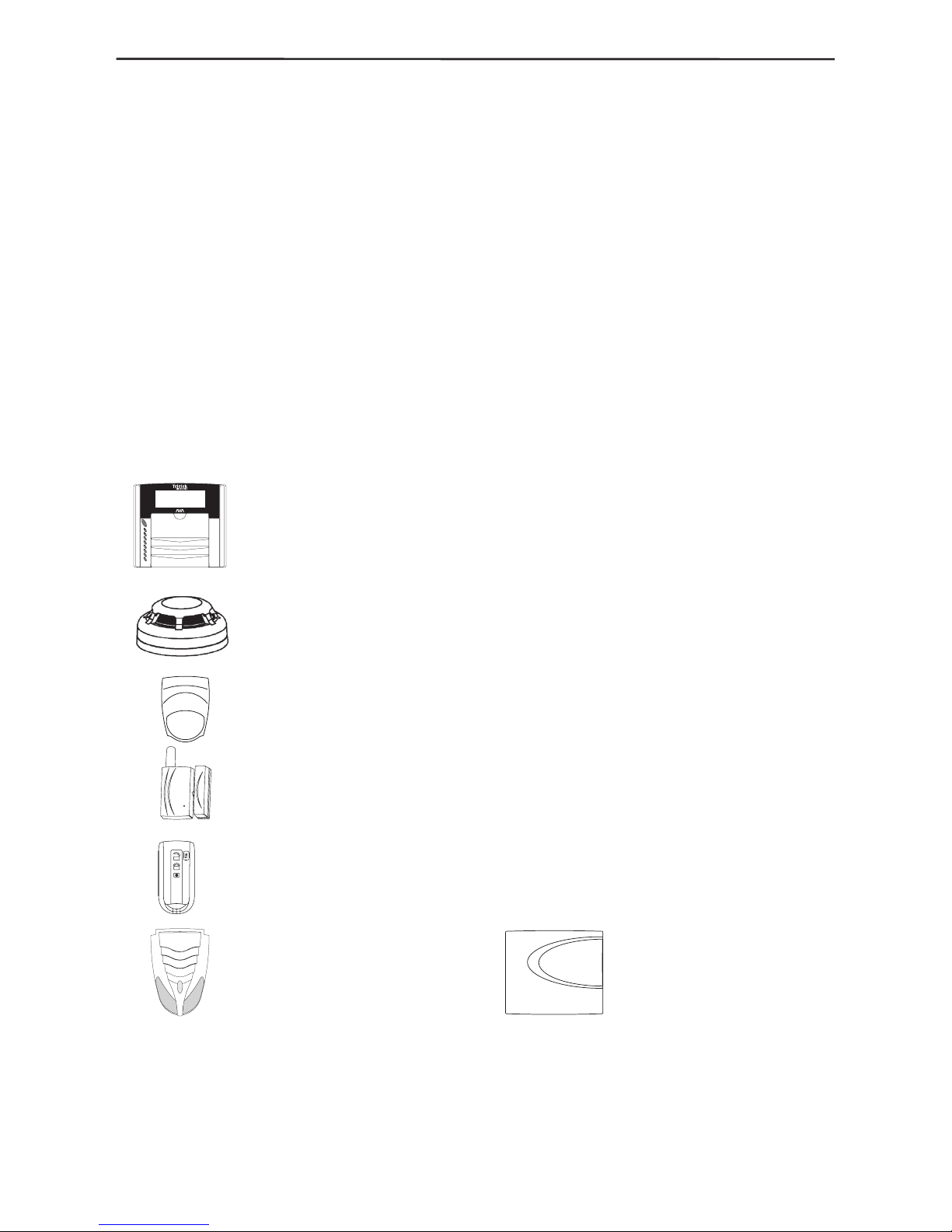
The system consists of a control panel, with a built-in LCD display and a keyboard,
and has a two-way communication with a set of various wireless devices: an infrared
detector, a magnetic contact, a re detector, a remote control, a repeater-module, a
wireless keyboard and a wireless outdoor siren - Fig. 1. In addition to the main panel,
a telephone communicator (dialer) can be installed to notify about various events and
offering remote control over some of the system functions as well. In addition the panel
and the repeater have two wire zones and four programmable outputs (PGM) each.
Figure 1. AVA control panel and the different wireless devices which could be enrolled
into the system conguration.
Page 5
1. General Information 5
The system supports up to 22 wireless devices, allocated to six different security groups.
Arming any group depends on its type which can be programmed independently. The
different types of groups are: entry-exit, follow and instant.
The system can support up to six Arming and six Disarming functions. The detector
groups to be Armed and/or Disarmed for any individual function are additionally
programmed to which of the programmable outputs (PGM1 – PGM4) they shall generate
a signal. The Arm and Disarm functions can be activated via the 16 user codes from
the control panel keypad, the wireless keyboard or from the remote control.
The AVA Wireless System supports three types of panic functions, which can be activated
from the control panel keypad, the remote control or from the wireless keyboard.
The system operates in real time and stores information about the latest 256 events by
date/hour/minute, which can be reviewed from the control panel keypad.
The system also accommodates programming a monitoring PC software (UDL) to be
used for alarm system control by telephone line, §3.8.4, page 52.
1.2 Supported Wireless Devices
AVA Keyboard (VG) is used to monitor the status of the system, for
arming and disarming the alarm panel. The keyboard has one wire
input zone used to connect a magnetic contact in case the keyboard is
installed on a wall close to a door. The keyboard may have an option for
play-back of 7 voice messages.
FD100TE Optical-Smoke Fire Detector for reporting re events with
sensitivity level adjustment options.
AVA P-Rex Infrared Detector for reporting movement, with an option for
wall or stand mounting.
MC100TE Magnetic Detector for door or window frame installation with
an option for rolling shutter control.
RC102TE Remote Control with panel visual and sound indication for
sending and receiving messages about the system status - whether
armed or disarmed, as well as whether the system is in alarm mode.
Detailed information on installation, enrolment and adjustment of the various wireless
devices is provided in their individual manuals.
Outdoor siren SR200R Repeater-module
Page 6
6 1. General Information
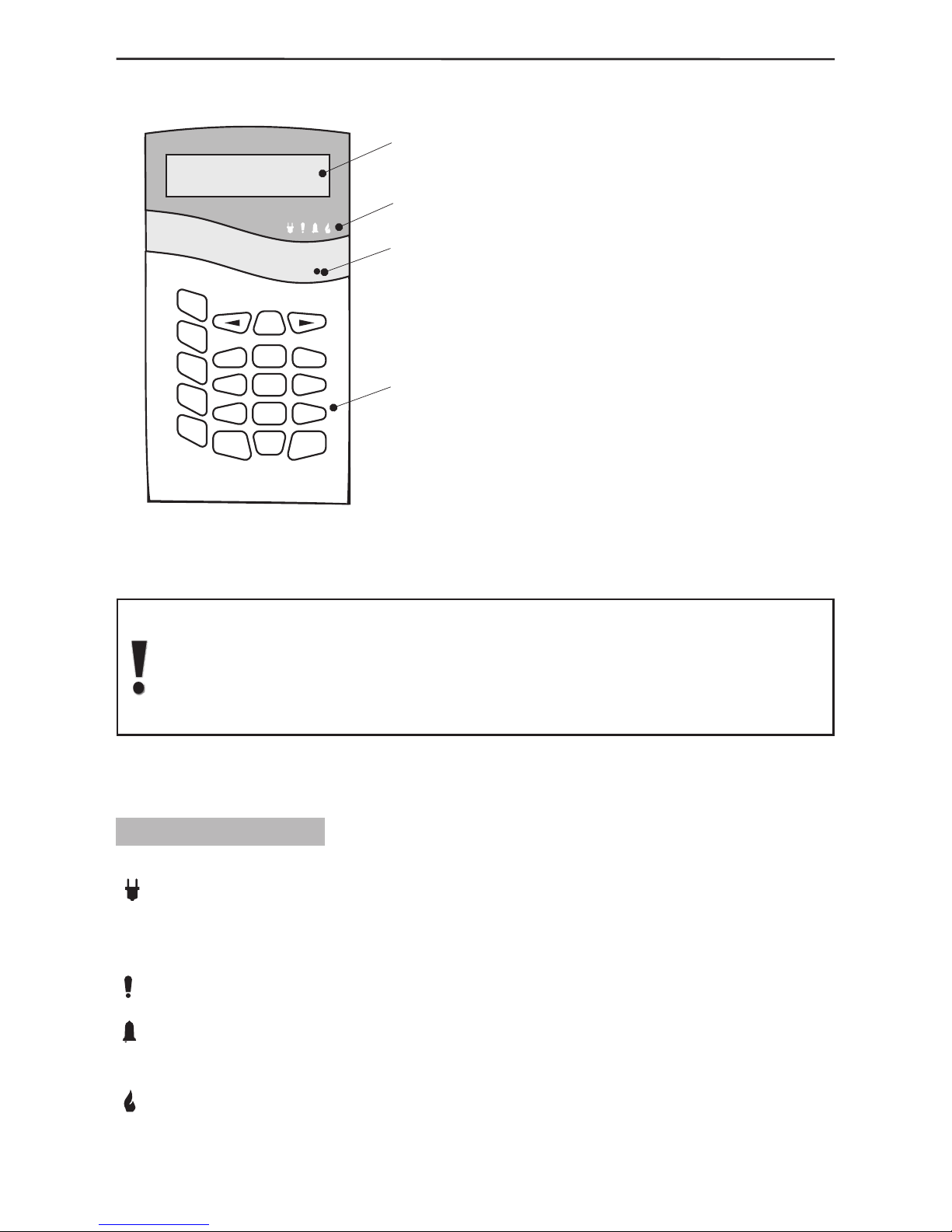
1.3 Control Panel Keyboard
The main panel keyboard consists
of an LCD Display, LED Indication
and 20 buttons with general
and special functions. A beep is
generated to acknowledge the
pressing of any button. A sound
signal is also used to indicate where
a specific operation is accepted or
rejected. The control panel sound
signals are explained in detail in
§1.3.5, page 8.
The user or engineer codes provide
access to the various alarm system
programming and control menus
unless where the Single-Touch
Buttons option has been activated.
The default value of the user menu code is 0000, and the engineer code is
7777. Any changes in both access codes is described in detail in §3.3 User
Programming, page 38. The access codes shall restore their initially preset
parameters only after complete nullication (full system reset) of system
parameters.
The programming and control menus and submenus have been numbered and are
located in a tree structure – see The Appendix: General Structure of System Menus.
1.3.1 LED Indication
There are four LEDs on the main panel keyboard which indicate:
220V (green) - lights up permanently to indicate mains power supply and turns
off when disrupted. The indication can be delayed in time via programing - §3.6.5
Programming Backlight Turnoff Time and Generating of an Event for Mains Power Lost,
page 45.
TROUBLE (red) - lights up to indicate an open tamper in the system; blinks to indicate
system trouble. When lit it is recommended to contact your installer.
ALARM (red) - lights up permanently to indicate an alarm event; blinks to indicate
entry and exit countdown time for encouraging relative actions for disarming or evacuating
the site.
FIRE (red) - indicates a re in the premises.
Buttons
LCD
Display
2
5
8
0
CLR ENT
PRG
ARM
BPS
TRBL
MEM
1
3
4
6
79
DISARM
LED
Indication
MIC
Microphone
Figure 2. Elements of the
control panel keyboard
Page 7
1. General Information 7
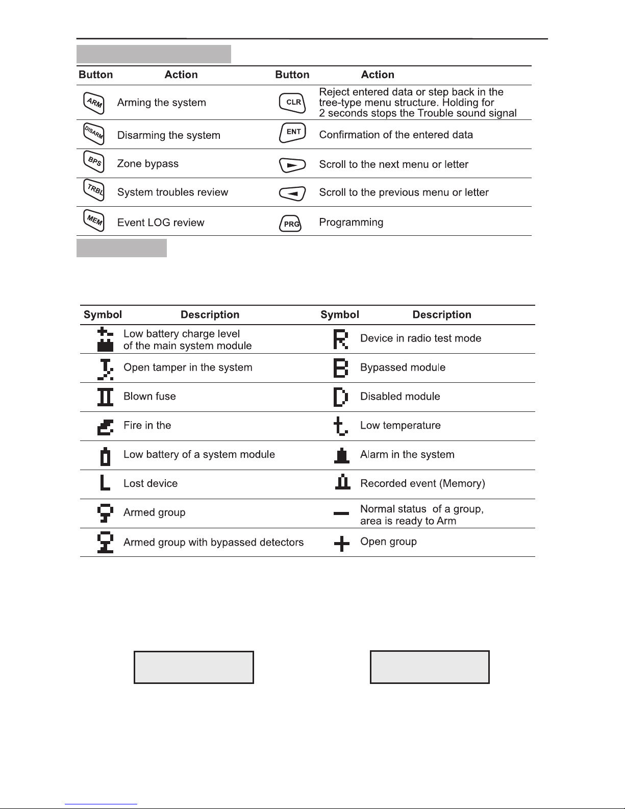
1.3.2 Button Functions
1.3.3 Display
The AVA Wireless System avails of an alphanumeric display (2 x 16 characters). The
following specic symbols have been introduced to account for various events:
In normal working mode time and date are displayed and the user can choose from
between two screens - Screen 1 with information of groups status, set by default and
Screen 2. The type of screen is selected from the System Parameters Menu as described
in §3.6.1 Programming Display Parameters, page 43.
Screen 1 Screen 2
The display is lit by a LED backlight with controllable brightness and a power saving
option when the keyboard is not in use and/or during power failure – for details see
§3.6.5, page 45.
premises
123456 Mon.04/09
------ 10:51
Teletek Wireless
Mon. 04/09 10:51
Page 8
8 1. General Information
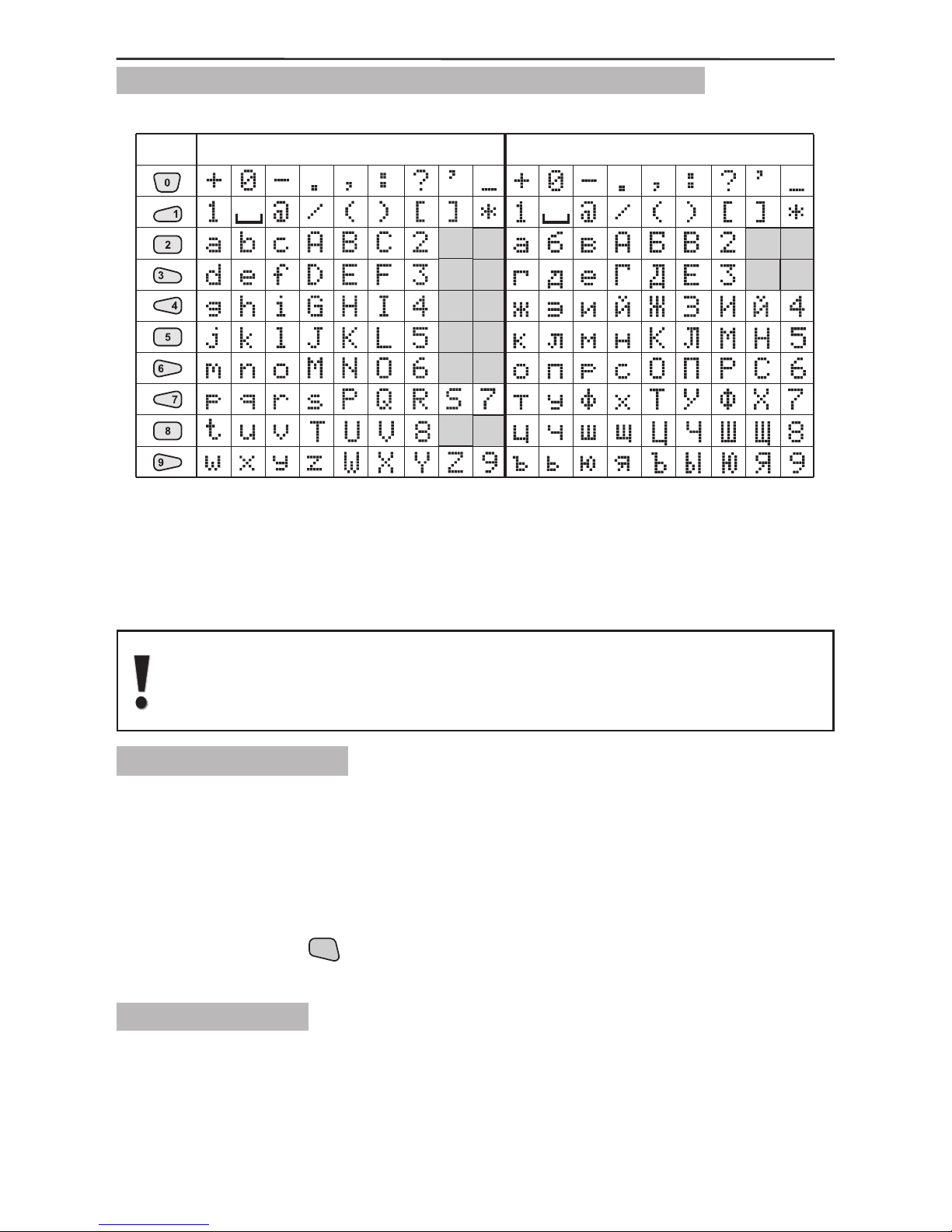
1.3.4 Symbols Used for Text Introducing from the Keypad
Use the keypad buttons numbered from 1 to 9 to introduce the symbols for entering
group and detector names, for adjusting the time and date, etc. In text editing and
entering mode the button is repeatedly pressed until the required letter, digit or symbol
is obtained. The available symbols of the pressed button are displayed in the top righthand corner when introduced.
Letters in Latin are displayed if the English version of the software is
selected, and in Cyrillic in the Bulgarian version.
Switching over between the different languages is described in §2.5, page
16.
1.3.5 Keypad Sounder
Beep - when pressing a button;
Long beep - reject an action;
One long beep followed by a few short ones - conrmation signal;
Short beeps - exit time is running;
Fast beeps - entry time is running, an important event such as Tamper, Fire, etc. has
occurred;
Double beep every 20 seconds - trouble indication. The double beep signal can be
stopped by holding the
CLR
button pressed for 2 seconds;
“Chime” - activated entry-exit zone.
1.3.6 Built-in Siren
The AVA Wireless Security System has a built-in siren 90dB which could be freely
programmed to become active in case of specic system events and continuity of siren
alarm. For details when programming the built-in siren parameters see §3.6.2 Built-in
Siren Parameters Programming, page 44.
Buttons Latin Cyrillic
Page 9
2. System Installation 9
Brick wall
Low Reduction
Steel Reinforced
Concrete
High Reduction
Low Reduction
High Reduction
2. System Installation
2.1 Wireless System Installation Basics
Planning the Installation. Situating and Selecting the Installation
Location.
In order to achieve the best efciency of the wireless system, prior to installation plan
the location of the control panel and the wireless devices within the premises. The
AVA Wireless System communicates two-way with all enrolled devices and therefore
it is advised to observe the following recommendations when selecting the installation
location.
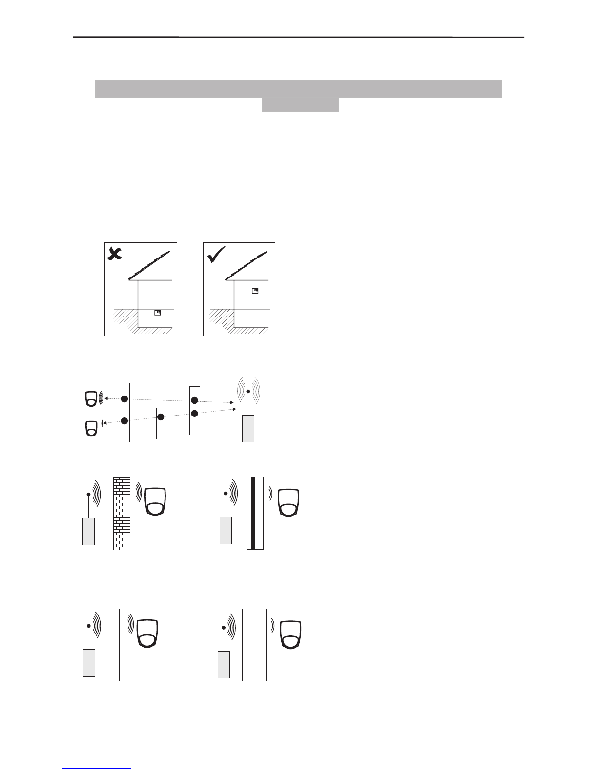
1. Do not install the control panel in premises located below ground level - Figure 3.
Where this cannot be avoided, install the panel as high as possible.
Figure 3. Selecting the control panel
installation location.
2. Minimize the number of obstacles between the control panel and the wireless
devices – Figure 4.
Figure 4. Minimizing the number of
obstacles.
Figure 5. The construction and
the width of the walls between
the premises also affect the radio
signals transmitted between the
devices.
Page 10
10 2. System Installation
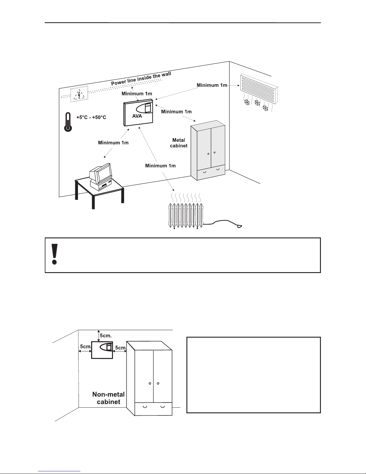
3. No objects or obstructions, which may reect or absorb radio waves, as well as
devices causing interferences, must be situated in close proximity of the control panel
installation location – Figure. 6.
Do not install the panel close to sources of strong radio elds as these can
cause interference and thus diminish the serviceability of the system and
its radio band.
4. The control panel should be installed approximately within the centre of the
premises that are to be guarded and the span to the various wireless devices should be
relatively uniform.
5. Where the control panel is installed in a corner at least 5 cm of space should be
left around the box for proper ventilation – Figure. 7.
Figure 7.
Figure 6.
The control panel installation location should be dry and should not
be subjected to harsh temperature
changes.
The control panel should be installed
close to grounding and telephone
cables.
Page 11
2. System Installation 11
2.2 Control Panel Installation
2.2.1 Selecting the Installation Location
The installation location of the control panel and the various devices shall
strongly inuence the efciency of the wireless alarm system.
In order to achieve best performance for the radio signal and respectively
for the good serviceability of your wireless alarm system, please follow the
recommendations given below.
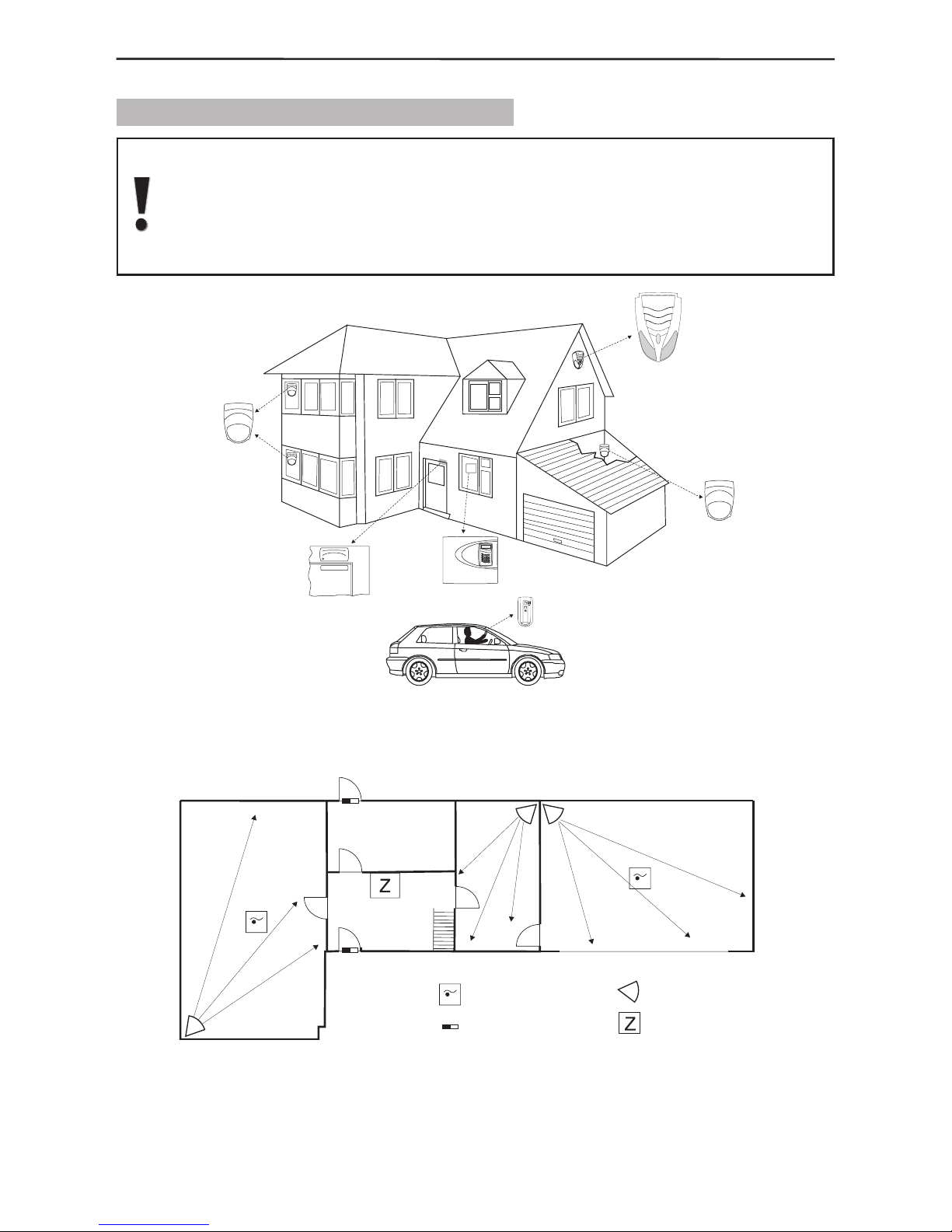
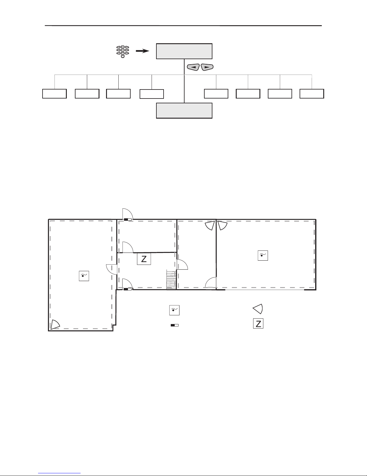
Figure 8. A model situation of locating the AVA Control Panel and the wireless devices
enrolled in it.
Figure 9. Location of the AVA Control Panel and the wireless devices enrolled in it
within the premises. The Control Panel is located approximately within the centre of the
alarm system.
PIR detector
A V A P-Rex
PIR detector
A V A P-Rex
Outdoor siren
SR200R
Magnet
Contact
МС 100 ТЕ
Control
Panel
A V A
Remote
Control
RC 102 TE
LEGEND:
Fire Detector
Magnet Contact
PIR Detector
Control Panel
Page 12
12 2. System Installation
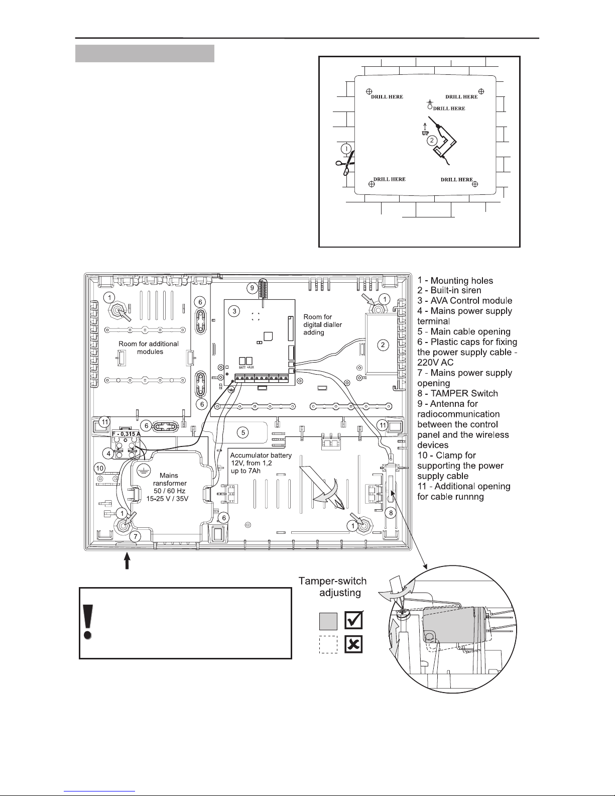
2.2.2 Box Installation
1. Use the provided prole board (see
the back of the packaging) to drill mounting
openings (6 - 8 mm) at the installation
location - Figure 10.
For mounting onto a brick wall it is
recommended to use 4,2x35 DIN 7981
screws and 6x30 UN 9802 plugs.
2. Install the back of the box on the wall
and adjust the tamper-switch as shown in
Figure 11.
Adjust the temper-switch with
the help of the screw below it so
as viewed from aside to be
horizontal.
Figure 11. Location of the modules in the box and the electrical
connections among them.
Template
Figure 10.
Page 13
2. System Installation 13
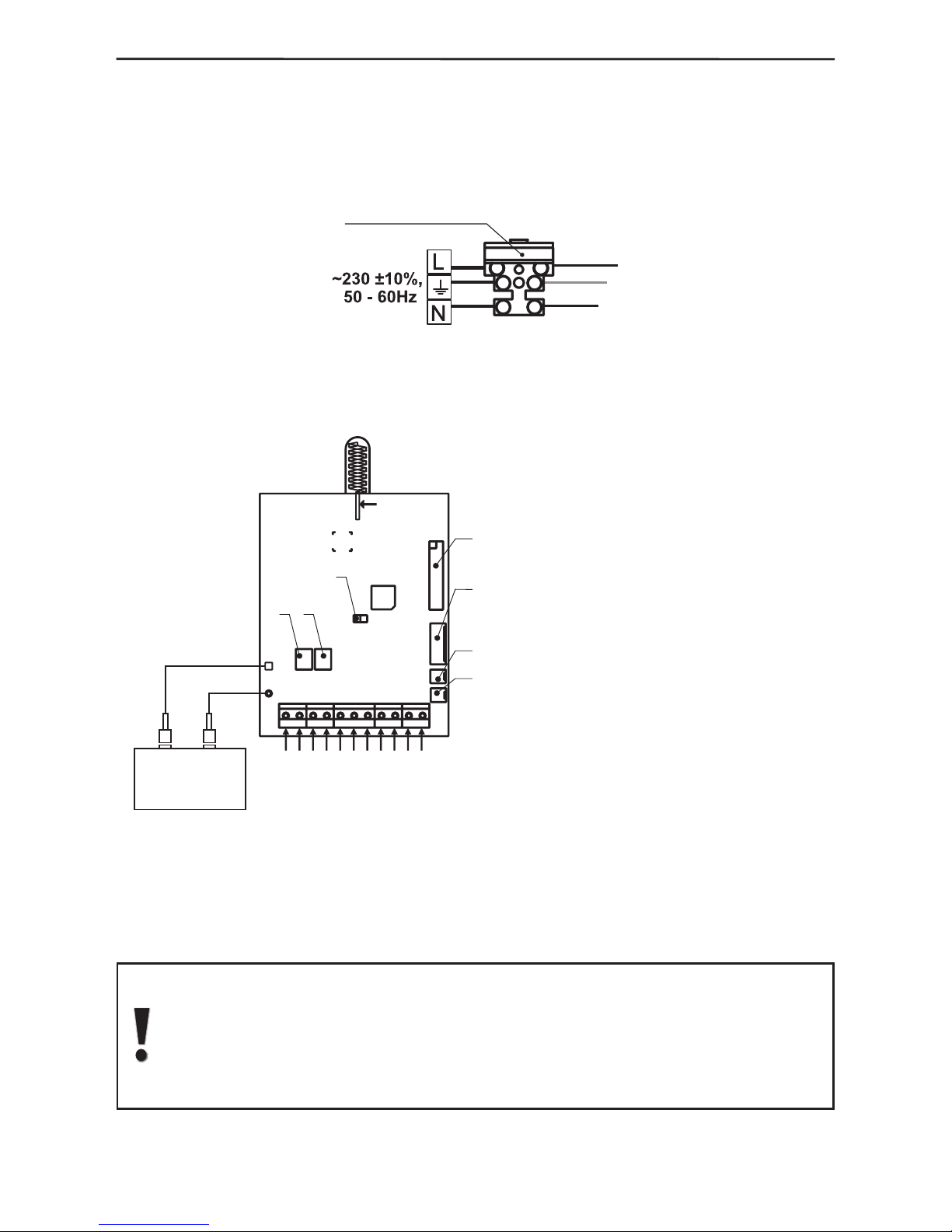
3. Run the mains cable (for 230V AC, 50/60Hz) through opening 7, shown in Figure 11
and connect it to the mains terminal – Figure 12. Use one of the three plastic caps to x
the mains power cable in Clamp 10 (Figure 11). With the additional provided spare parts
kit use the two screws (tapping screw 2.9x13 cross slot DIN 798) to secure the cap to
the clamp.
Figure 12. Connecting to the mains terminal.
4. Connect the ribbon cable to the display and the one of the built-in siren to the main
module see Figure 13.
Figure 13.
Overall view of the main module and description of the inputs and outputs.
5. Install the charge battery (12V DC, 1.2 ÷ 7 Ah; it is recommended to use a YUASA
#NP-12 model) designed to provide backup power supply in case of mains failure
(230V AC).
NOTE that the battery has to be connected to the AVA control module AFTER
the initial system start-up - see §2.3, page 15.
Observe the polarity of the battery terminals. Otherwise the self-recoverable
fuse BATT will turn out.
OBSERVE SAFETY MEASURES WHEN USING 220V!
F-TYPE FUSE 0,315A
AC
GND
Zn1
PGM4
PGM3
PGM2
PGM1
AUX
Zn2
ANTENNA
AT TENTION
DO NOT TOUCH
THE ANTENNA:!
1
2
3
4
5
6
7
-
-
-
-
-
-2А,
-±
,
~230 ±
±
-,
,
-
RESET Jumper
Flat terminal for connecting the keypad
Flat terminal for connecting the dialler
Connector for connecting the built-in siren
Connector for connecting the tamper-switch
Battery Fuse
type self-recoverable
AUX Output Fuse 1A,
VAC 10%, 50 60Hz
- 12V,
1A
-
-
type self-recoverable
Mains Power Supply
Power Supply
for detectors with consumption up to
Programmable output
with power transistor
Programmable outputs
with small-power transistor
Terminals for wire zones
Common ground
AC
AUX
PGM1
PGM2-PGM4
Zn1, Zn2
GND
BATT
±AUX
Cable shoes for connecting
the accumulator
+
-
1
2
3
4
5
-
+
6
7
black
red
Accumulator
battery
V, 1,2 7Ah12
Page 14
14 2. System Installation
2.2.3 Connecting Wire Zones and Programmable Outputs
The system programmable outputs (PGMs)
are transistor type (NPN) with a 1K resistor
in the collector. By default all PGMs are in
NC state (normally closed contact) – i.e. the
programmable output is ON and the polarity of
the output is grounded. PGM1 is a power output,
whereas PGM-s 2, 3 and 4 are low current
outputs. The outputs are designed to be used
as open collectors: i.e. for switching over from
load to ground. The additional 1K resistor in the
collector serves as an additional output level in
case the output is potential. Then serviceability
shall be restricted by the resistor.
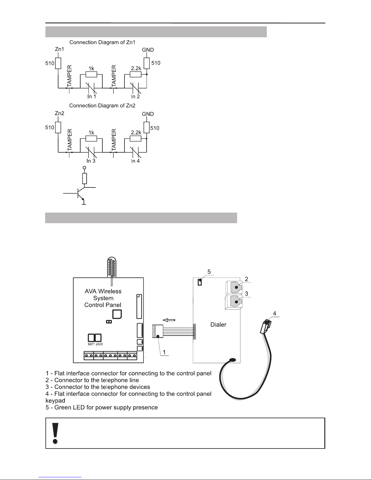
2.2.4 Connecting a Digital Communicator (Dialer)
Figure 15 shows how to connect the CPC 100 TE Digital Communicator board to the
control panel. If the connection is correct and power is supplied to the control panel a
green LED will begin to blink in the top left-hand corner of the communicator.
Connect the Dialer to the AVA control panel only when the main power
supply is switched off. The Dialer has to be the rst device connected to
the telephone line, in order to provide it with highest priority in operation.
Figure 15.
Dialer
connecting
Figure 14.
How to connect the wire zones and scheme of
a programmable output
+12V
1k
GND
PGM
PGM
Hardware
Page 15
2. System Installation 15
2.3. Initial Start-up of the Control Panel
After the system is installed, it should be started-up: i.e. the power supply is turned on
(initial power supply) with a mounted jumper for full reset (located next to the processor
– see Figure 13, page 13).
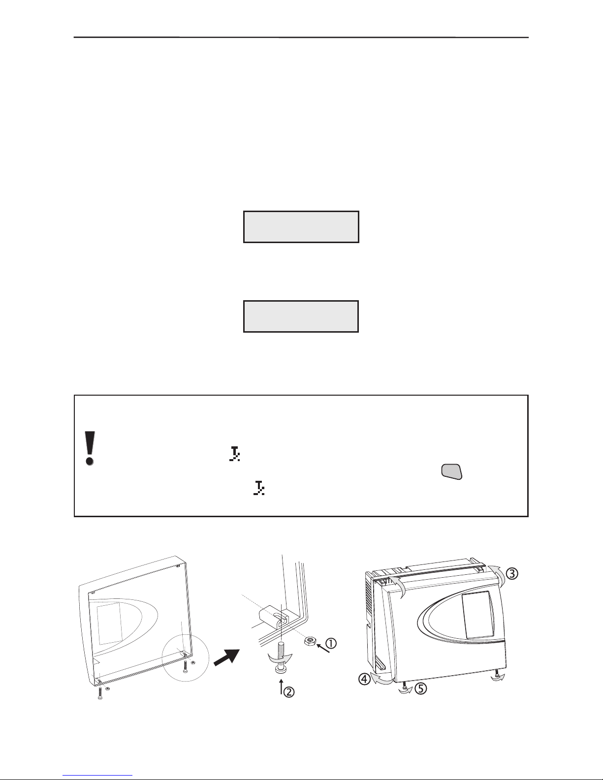
Before performing a full system reset (to remove the jumper from the control module,
next to the processor), prepare the box to be closed by placing the nuts from the spare
parts kit in the holders on the internal side of the cover – Figure 16. Turn the two M3x16
screws into the cover openings so that they join the nuts but do not go all the way.
Turn on the main power supply with the mounted jumper for full reset of the control
module. The system will begin to operate and the display will indicate:
Remove the jumper and wait for several seconds for the system to restart. The display
will indicate:
Connect the battery terminals, observing the polarity.
Place the top cover and wind the screws to the end, as shown in Figure 17.
After performing a full system reset AVA system will automatically go on
normal working mode and a sound signalization for open tamper in the
system (the tamper of the control module) will turn on, and on the LCD will
start blinking symbol
.
The sound signal can be stopped by single-pressing the
CLR
button of
the keypad, and symbol
will disappear after the top cover is nally
installed and the tamper-switch is closed.
please remove
Reset Jumper!
reseting
please wait
Figure 16. Figure 17.
Page 16
16 2. System Installation
2.4. System Programming Sequence
After installing the AVA Wireless Alarm System control panel and performing a full reset,
there shall be no enrolled system devices, and its system parameters shall be set at
default values (for more information see also the Appendix: General Structure of System
Menus). In order to programme and prepare the system to operate after restart, it is
recommended to perform the following sequence of actions:
1. Install and enrol the wireless devices according to the algorithm (example) set in
§2.6.1 Enrolling of new devices, of this manual. It is obligatory to perform the described
radio test at the place of installation.
2. Programme the devices according to the needs (in case there is a difference from
the default parameters) by following the instruction in §3. It is recommended that each
device be given an individual name thus providing perspicuity to the system and easing
the user in understanding the status and performance of the devices – see Example of
Grouping sensor areas in §3.4, page 40.
3. Programme the Detector Groups according to the desired organization and functioning
of the system. For ease set the Groups names according to their functions.
4. Programme or modify the Arm and Disarm functions because they are operated by the
user and can also be activated from the buttons on the remote control.
5. Programme the necessary user codes and functions which have been assigned to
system activation rights and attributes.
6. If necessary programme the outputs.
7. If necessary change system parameters.
8. Do not forget to instruct the user how to operate the system and where necessary to
seek installation assistance.
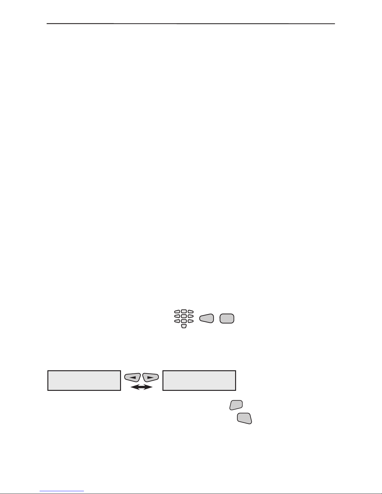
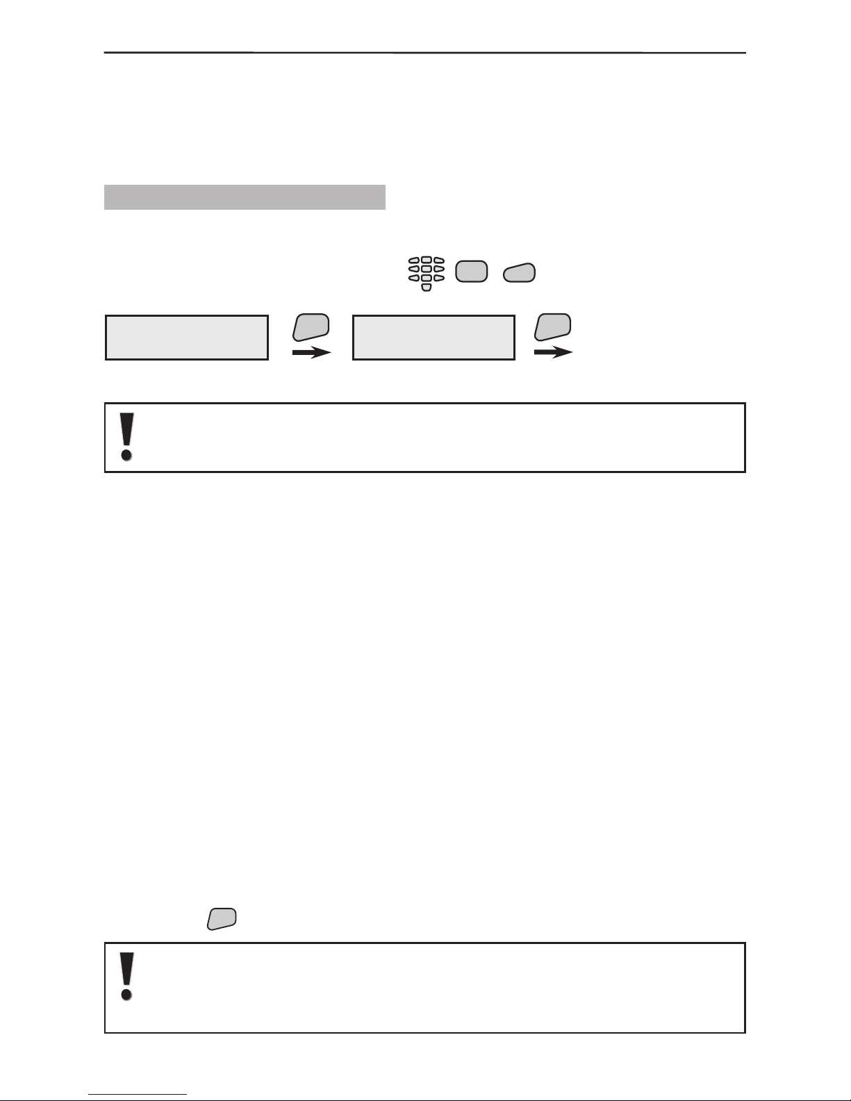
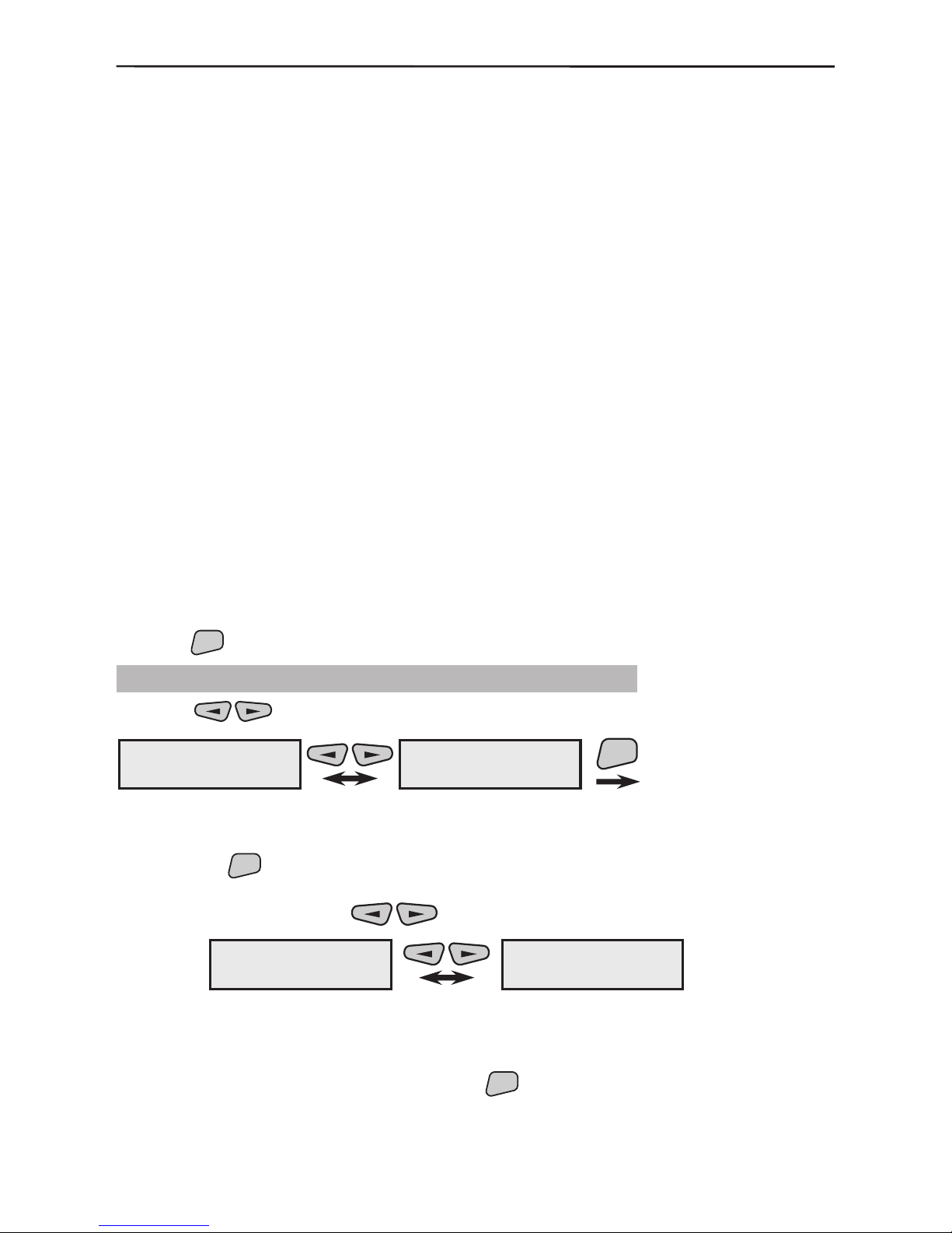
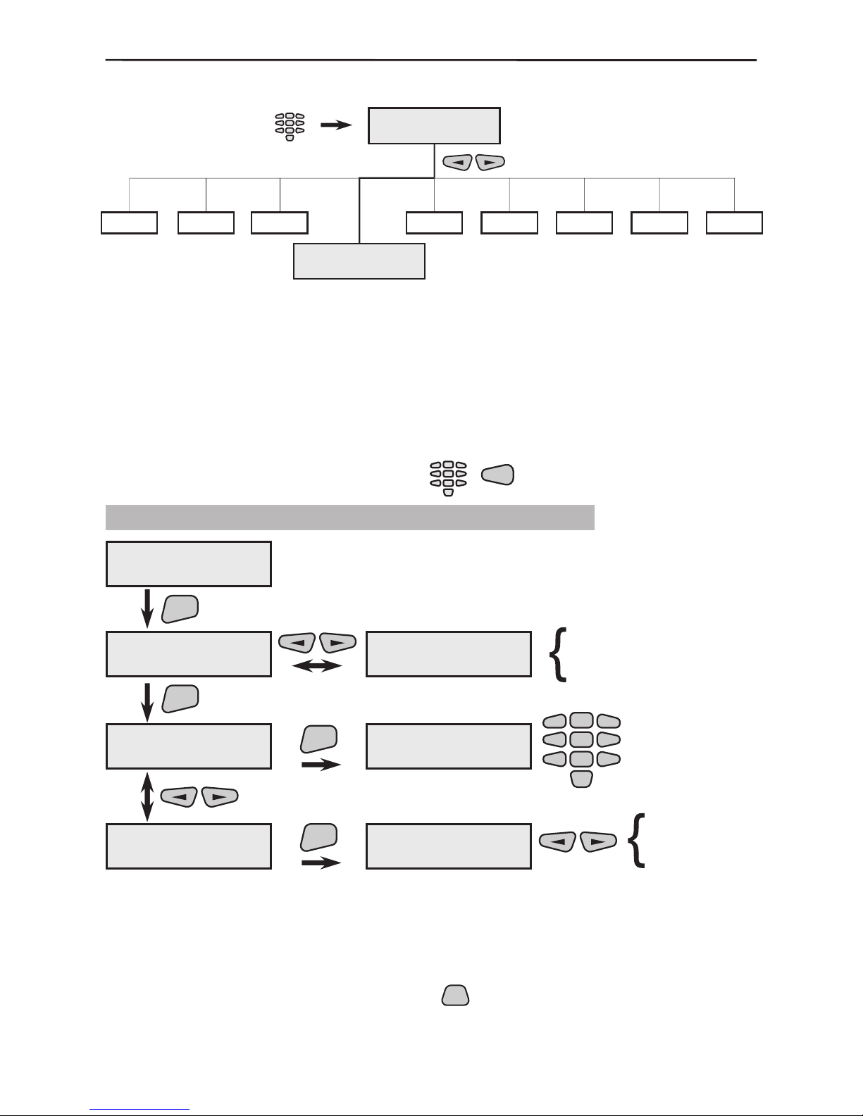
2.5 Language Selection
During initial start-up the menus by default are in English. In order to change the menus
over to other language select in succession:
This enables prior access to the system parameters and the opportunity to select the
desired language. After selecting the indicated buttons the screen has the following
view:
You can choose the selected language by pressing the
ENT
button for conrmation.
After the language is changed and conrmed, press the
CLR
button twice to return to
the initial menu screen – see also §1.3.3 Display.
Engineer
code-7777
7
8
8)Language
english
8)Language
български
Page 17
2. System Installation 17
2.6 Installing Wireless Devices
The Control Panel communicates with the wireless devices via a two-way radio
connection. In order for an AVA System to communicate with the wireless devices, they
must rst be enrolled in the system so that it can identify them. Every wireless device
has a unique house address (HA) with which it is memorized in the conguration of the
system. All wireless devices are enrolled according to a uniform algorithm.
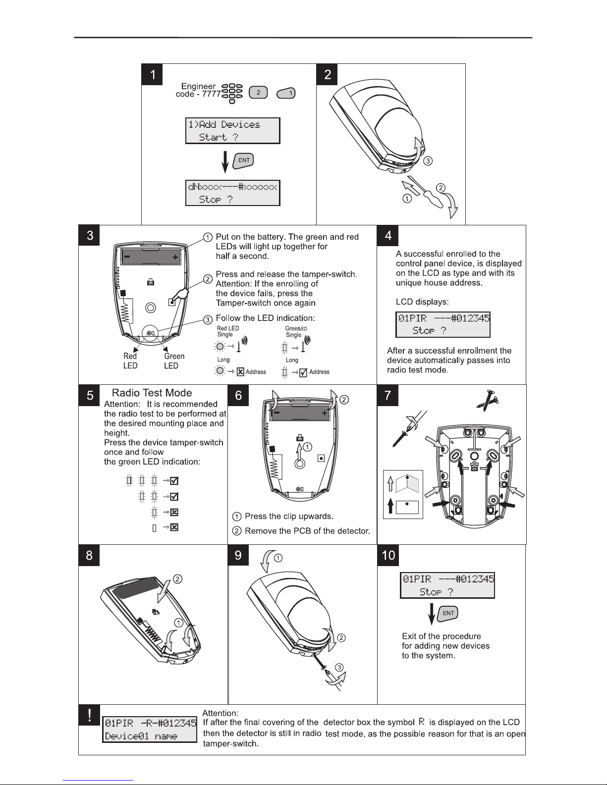
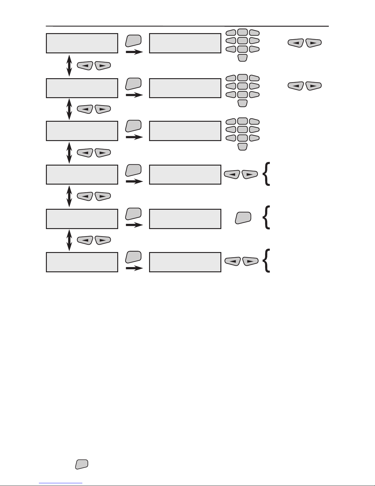
2.6.1 Enrolling of New Devices
1. Start a procedure for adding new devices to the system.
Select in succession:
2. Open the cover of the device, as shown in its installation instructions.
Note: The enrolment of RC 102 TE remote control do not require opening of
its cover. Follow the given enrolling procedure in the individual operation
instruction of RC 102TE.
3. Place its battery, paying attention to the polarity. The green and the red LEDs will
light up for half a second.
4. Single-press the device tamper, in order to transmit radio ID signal to the panel.
If enrolment has been successful, the display of the control panel will show information
about the type of device and the specic house address.
If the device has not been registered in the control panel at the rst attempt, press its
tamper again.
After the device has been enrolled, it will automatically pass into radio communication
mode.
5. Go over to the device installation location and perform a radio test. This
will ascertain whether the selected location has good radio signal conditions and
communication with the control panel. Single-press the device tamper-switch. If the LED
blinks two or three times in green, then the radio signal and communication are good and
the device can be installed at the selected place. If the LED blinks green once or does
not blink at all, then the radio communication is poor and the installation place must be
changed (i.e. move the device to a different place in the same room). Note that the LED
blinks in red when the device is sending radio signal to the base.
6. Install the base of the device following the instructions provided in its individual
manual.
7. Close the device box, paying attention for its tamper-switch to be also well closed.
In about 5 sec. after closing its inclosure, the device will exit the radio test mode and
will begin normal operation.
8. Press the
ENT
button to exit the procedure for adding new devices.
If after closing the box of the device, the symbol R blinks on the display
of the control panel, that means the device is still in radio test mode. The
device will leave this mode only after its tamper-switch is closed and
remains closed for more than 5 sec.
Engineer
code-7777
2
1
1)Add Devices
Start ?
dNxxxx---#xxxxxx
Stop ?
ENT
ENT
Exit of the procedure
for adding devices
to the system.
Page 18
18 2. System Installation
Example for enrolling a wireless device - infrared detector:
Page 19

2. System Installation 19
2.6.2 Deleting the House Address of a Device
Every wireless device communicates with the control panel within the authority of its
unique house address (HA). In order for a specic device to be enrolled in an AVA
control panel, it must not have an HA, which has been attributed from another system,
i.e. used to be enrolled in one control panel, but has had to be moved and enrolled in a
new AVA Wireless System. In such case the device house address needs to be deleted
prior to its enrolment in the new system.
The deletion is performed analogically for the different wireless devices:
1. Power up the device (remove and place back its battery) while the tamper is open:
i.e. open the device, if it has been powered prior to this moment, leave it without any
power supply for about 10 sec. and then power it while the tamper is open. A red LED
starts blinking.
2. While the red LED is blinking press quickly the device tamper-switch at least 3
times. The red LED lights up continuously for 1 sec. to indicate a deleted HA of a device.
After such restart, the device will have a deleted HA and the pressing of the tamperswitch again will attempt to enrol the device in the control panel.
The rst enrolled device in the system will be added to Group 1, the second
to Group 2, and any following one – to group 3. Keep in mind that all re
detectors following enrolment are by default added to Group 6.
All enrolled devices can be further re-programmed according to your
choice and needs
It is recommended to double check your programing table after completion in respect
to devices place, group and name. It is also advisable every device to be assigned
a specic name so that it can be easily identiable within the system – see §3.1.2
Common Detector Parameters and the Example for Programming Detector Groups and
Programming Functions in §3.4.
As a rule all wireless devices are programmed to send test messages to the control
panel over a specic time interval. This is brought about by the need for the control
system to monitor at all times their reliability and performance. The test message time
(XX minutes) is the same as for all other devices and can be programmed – see §3.1.1
Common Parameters.
All devices have to be enrolled in the system again only where a full reset
of the control panel has been performed (see §2.3) or the device house
address has been deleted. All device HAs are stored in a separate power
independent memory and cannot be deleted in case of simultaneous
failure of main or back-up power supply.
If a wireless system with enrolled devices is turned off, the devices’
batteries MUST be removed in order not to be drained out of power in their
continuous attempts to communicate with the panel.
Page 20
20 3. Programming
3. Programming
System parameters programming is not required. Every added device adopt’s a default
parameters which ensures the normal function of the system - see The Appendix: General
Structure of System Menus. The installer avails of the opportunity to programme them
further depending on the specic installation. In order to have clarity in the system, we
recommend to change (rename) the devices and user names.
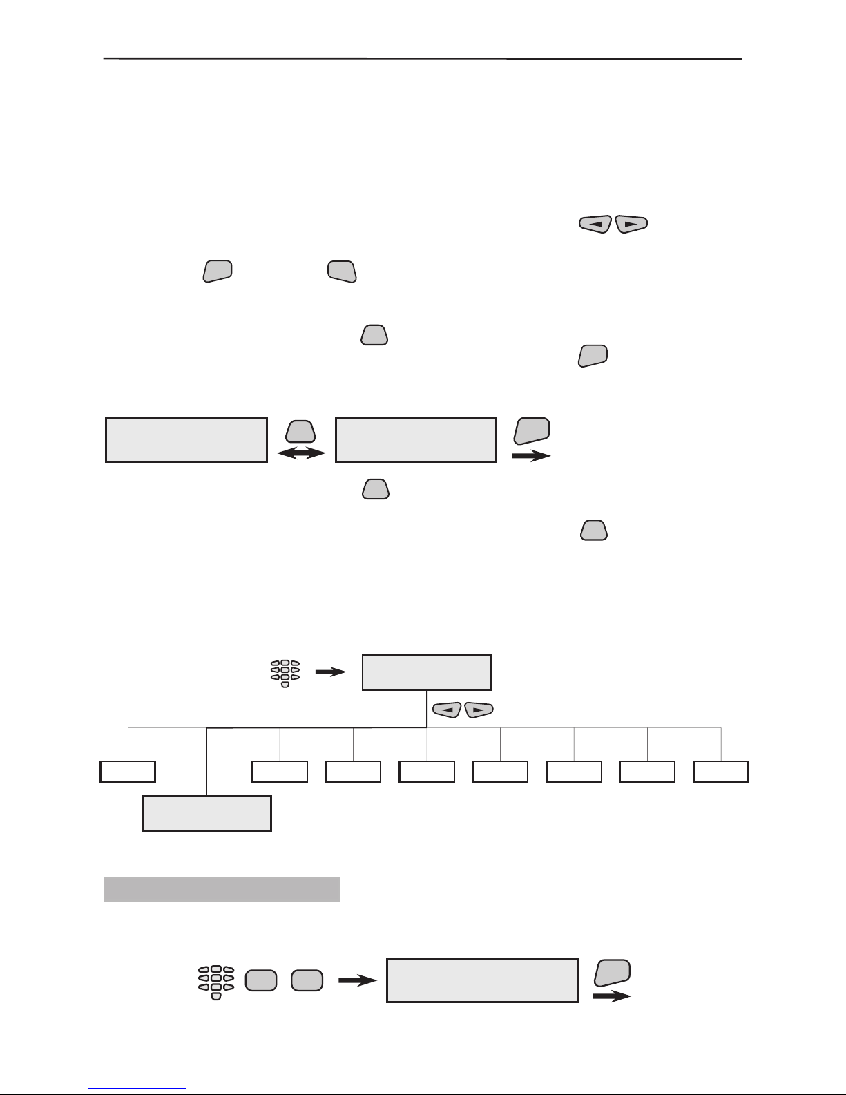
Programming system parameters is done after entering a valid engineer code – see
§1.3. Scroll through the main system menus with the help of the
buttons.
Access to a specic programme menu and conrmation of the introduced data is done by
pressing the
ENT
button. The
CLR
button goes one step back or rejects the introduced
data.
All active parameters in the system are marked with the “*” symbol and the inactive
– with the “-” symbol. Press the
PRG
button of the keypad to change the parameter
status of the respective submenu. Conrm the changes with the
ENT
button.
Example for changing the status of a system parameter (programming):
As the example indicates, after the
PRG
button is pressed, the active parameter, marked
with the “*” symbol, becomes inactive and is marked with the “-” symbol. Activating the
parameter a second time is analogically done by pressing the
PRG
button a second
time.
This type of programming applies to all menus in the system!
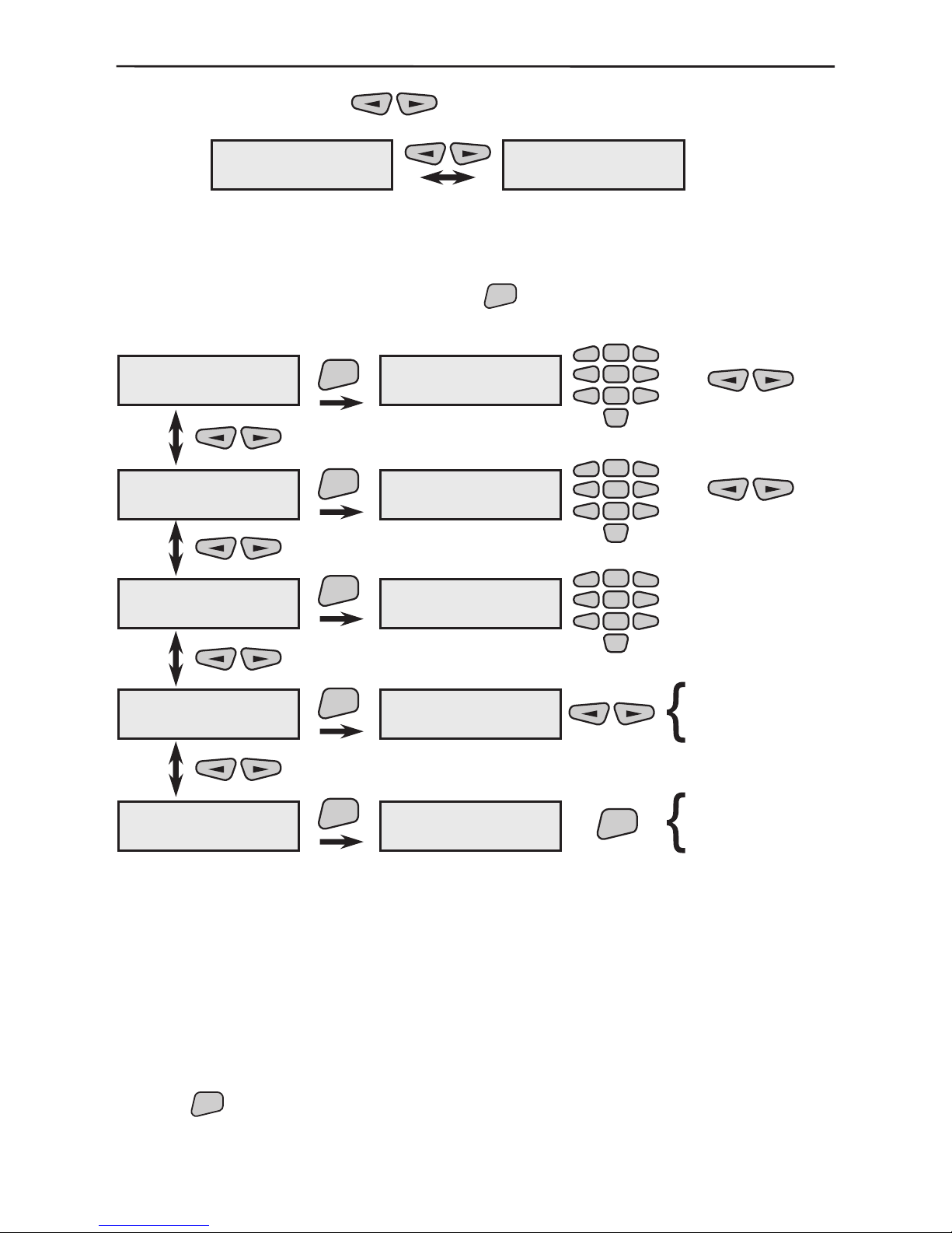
3.1 Device Programming
The device programming parameters are common or special.
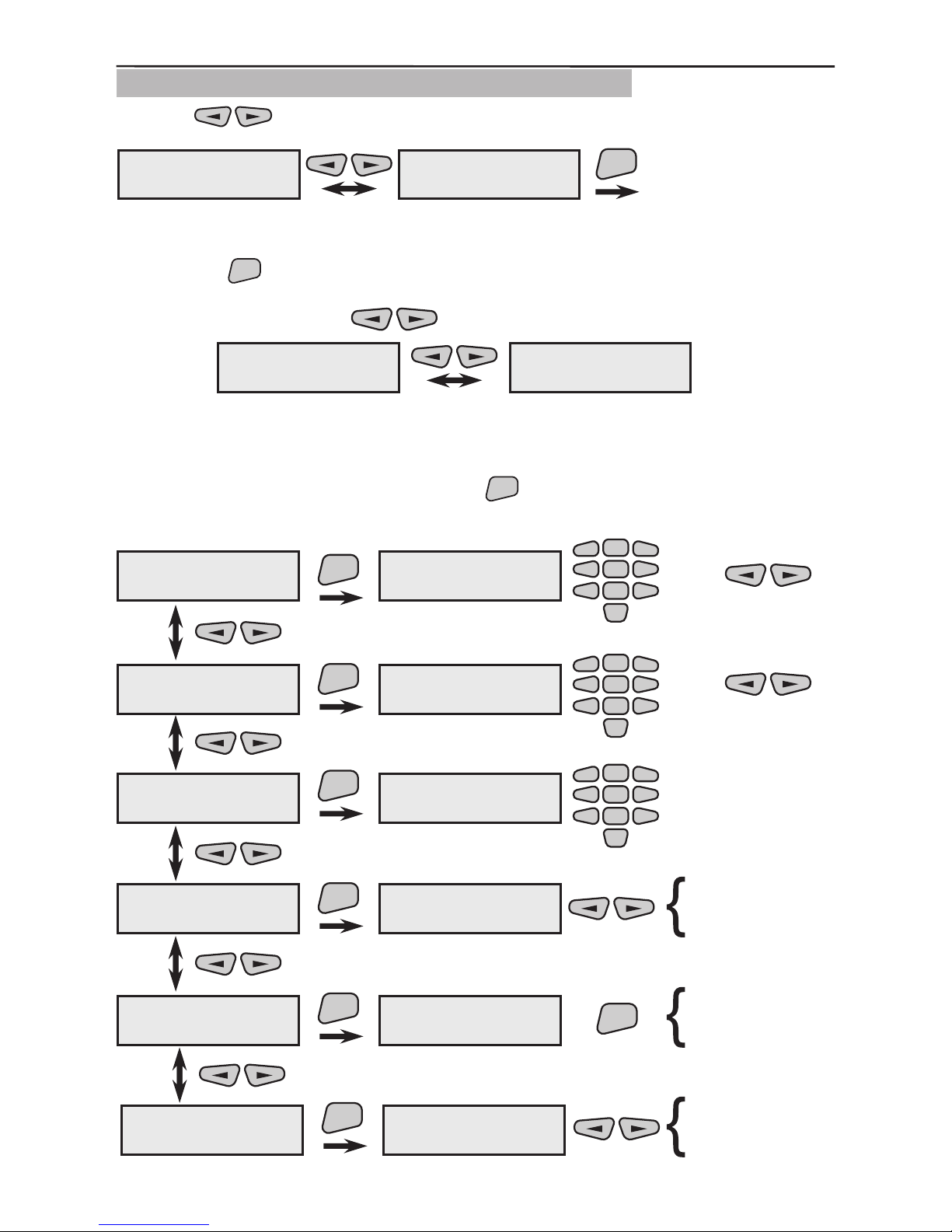
3.1.1 Common Parameters
Parameters, which are common to all devices, are programmed from this menu. To enter
the common parameter programming menu select in succession:
Engineer
code-7777
Engineer Menu
Engineer Menu
2)Devices
1
3
4
5
6789
ENT
Confirmation of
the changed
parameter.
1)LED config
* open
PRG
1)LED config
- open
2)Program Device
1)Common Prog.
Engineer
code-7777
2 2
ENT
Page 21

3. Programming 21
Two submenus can be programmed here.
Programme three parameters to specify what the wireless device LEDs should indicate. By default all three parameters are
active.
Programme the time for sending test messages to the main control
panel from each wireless device and how many repetitions should
be performed during the set period of time.
3.1.2 Common Detector Parameters
Use the buttons to select the next menu from the 2)Program Device:
After the
ENT
button is pressed LCD displays:
This is the submenu for programming the parameters of the rst enrolled and recorded
in the system device. The screen displays information about the number, the type and
unique house address of the device. Each device in the system has a submenu for
programming its parameters.
Two types of actions are possible from this screen:
1. All enrolled and recorded in the system devices can be scrolled through with the
buttons.
Example:
The rst enrolled device in the example is an infrared detector (01PIR) and the second is
a siren (02SIR). The devices have service names which can be edited.
1)Common Prog.
1)LED config
1)Common Prog.
2)Communication
ENT
ENT
1)LED config
* open
2)Communication
5min/1s/10times
* open
*ÒÕ/RX
* programming
5min/1s/10times
10min/2s/5times
20min/5s/5times
60min/2s/5times
2)Program Device
1)Common Prog.
2)Program Device
2)All Devices
ENT
dNXXX ---#000000
DevicedN name
dN
XXX
---
#000000
DevicedN name
-,
-
-
-,
- Device serial number
Device name given from the system
Current status of the device
House address of the device
Device name
which could be edited by the installer
1)LED config
2)Communication
01PIR ---#012345
Device01 name
02SIR ---#054321
Device02 name
Page 22

22 3. Programming
2. From the screen of each device press the
ENT
button to enter its parameter program-
ming submenu.
Three submenus can be programmed here.
The name of the wireless device can be freely edited in this
menu. Use the keypad to select the letters to write the new
name. A cursor is positioned under the letter to be edited. After
the new letter is selected, the cursor automatically moves on to
the next letter to be edited. A table with the available symbols is
provided in §1.3.4, page 8.
Attention: In this mode you can switch over the avaliable Latin and Cyrillic symbols and letters by single
pressing the
PRG
button.
The menu provides the opportunity for the device to be disabled or enabled. A disabled device is indicated by the letter
D
in the eld of its current status; the system operation shall not
be interfered with by its performance, but shall respond in case
of a message.
Example for a disabled device: -D-.
The menu provides an opportunity for complete deletion of the
device from the system memory and for enrolling a new one
in its place. Double conrmation is required for the request to
delete the device.
The position of every deleted device stays empty. If there are
some empty positions, and a new device had to be enrolled it
would be recorded into rst empty position in the system memory. For example, if positions 7 and 15 are free the rst new
device would be recorded in position 7.
Use the
ENT
button to conrm all entered data and changes.
dNXXX ---#000000
DevicedN name
ENT
Device01 name
1)Change name
Device01 name
2)Enable/Disable
ENT
ENT
Device01 name
ENABLED
disable?
enable?
Device01 name
3)Remove
1)Change name
Device01 name
-
2
5
8
0
1
3
4
6
79
ENT
Device01 name
remove?
ENT
are you sure?
1)Change name
2)Enable/Disable
3)Remove
Page 23
3. Programming 23
3.1.3 Programming of AVA P-Rex Infrared Detectors
Use the buttons to select the next menu from the 2)Program Device:
This is the menu for scrolling through and programming the parameters of all available
in the system infrared detectors. Two types of actions are possible from this screen after
pressing the
ENT
button.
1. The various enrolled and recorded in the system infrared detectors can be scrolled
through with the help of the
buttons.
Example:
The rst infrared detector (PIR01) in this example has been recorded as the rst system
device (01PIR) and the second (PIR02) as the third (03PIR). The names of the devices
have been edited according to their location within the system.
2. From the screen of each device press the
ENT
button to enter its parameter program-
ming submenu. For clarity we shall use PIR01 as a device name.
2)Program Device
1)Common Prog.
2)Program Device
3)PIRs
ENT
01PIR ---#012345
PIR01
03PIR ---#123456
PIR02
PIR01
1)Sensitivity
PIR01
2)Device Group
ENT
ENT
2)Device Group
N:01
PIR01
3)Change name
1)Sensitivity
0...7:03
-
2
5
8
0
1
3
4
6
79
ENT
3)Change name
PIR01
-
2
5
8
0
1
3
4
6
79
2
5
8
0
1
3
4
6
79
-
PIR01
4)Enable/Disable
ENT
PIR01
ENABLED
enable?
disable?
PIR01
5)Remove
ENT
PIR01
remove?
ENT
are you sure?
PIR01
6)LowTemperature
ENT
6)LowTemperature
not used
not used
-4 degree Ñ
-2 degree Ñ
0 degree Ñ
+2 degree Ñ
+5 degree Ñ
+15 degree Ñ
+25 degree Ñ )
or
or
Page 24
24 3. Programming
The menu allows for detector sensitivity adjustments. The
values that can be selected are between 00 and 07, where
the greater number shall be of higher sensitivity. The preset
default value is 03.
Reference to a group of sensors.
NOTE: By default the rst enrolled in the system device shall
be assigned to Group 1, the second to Group 2 and every next
to Group 3.
The performance is as described in §3.1.2.
The performance is as described in §3.1.2.
The performance is as described in §3.1.2.
This is the menu for adjusting the lowest ambient tempera-
ture reading (with precision of ±1°С) where the sensor can
operate. Upon reaching the programmed value, the control
panel shall generate and transmit via the communicator (if
such is available in the system) an EV_FREEZE_ALARM
event message – see Event-LOG Table, page 58. The occurrence of such an event will also be indicated with the t sym-
bol on the control panel display, but with no sound signal.
Where the ambient temperature rises above the value that
has been programmed, the t symbol will be removed and
the communicator will generate an EV_FREEZE_ALARM_R
event. Where the selected Low Temperature event for activating the output has been selected (PGM – see §3.3), any
temperature above that programmed shall restored the initially programmed status of the output. The preset default
option is not used.
Use the
ENT
button to conrm all entered data and changes.
3.1.4 Programming of МС 100 ТЕ Magnetic Contacts
Use the buttons to select the next menu from the 2)Program Device:
This is the menu for scrolling through and programming the parameters of all available
in the system magnetic contacts. Two types of actions are possible from this screen after
pressing the
ENT
button.
1. The various enrolled and recorded in the system magnetic contacts can be scrolled
through with the help of the
buttons.
Example:
The rst magnetic contact (MC01) in this example has been recorded as a second system device (02MC) and the second (MC02) as the fourth (04MC). The names of the
devices have been edited according to their location within the system.
2. From the screen of each device press the
ENT
button to enter its parameter program-
ming submenu. For clarity we shall use MC01 as a device name.
2)Program Device
1)Common Prog.
2)Program Device
4)Magnet Contact
ENT
02MC ---#234567
MC01
04MC ---#765432
MC02
1)Sensitivity
2)Device Group
3)Change name
4)Enable/Disable
5)Remove
6)LowTemperature
Page 25
3. Programming 25
The menu for programming the number of input pulses expected
to be introduced at the roller shutter control or expected to be
generated by the shock sensor (see instruction on installing and
servicing the MC 100 TE detector) can be set here.
Entered value of 00 means that to the input of the programmed
magnetic contact could be connected normal wire detectors
without using the magnetic contact itself. Entered value of 01
means that the magnetic contact is used together with the connected normal wire detectors. The rolling shutter set pulse values shall be within the range of 2÷250. It is recommended when
controlling rolling shutters the preset range to be the within value
of 2÷25. With a shock sensor the value depends on the stability of the construction in which the magnetic contact has been
installed and it is recommended that the preset values be within
the range of 20÷100, where the higher value shall mean a less
responsive sensor.
The performance is as described in §3.1.3.
The performance is as described in §3.1.2.
The performance is as described in §3.1.2.
The performance is as described in §3.1.2.
The performance is as described in §3.1.3.
Use the
ENT
button to conrm all entered data and changes.
MC01
1)Impulse Input
MC01
2)Device Group
ENT
ENT
2)Device Group
N:02
MC01
3)Change name
1)Impulse Input
counter:009
-
2
5
8
0
1
3
4
6
79
ENT
3)Change name
MC01
-
2
5
8
0
1
3
4
6
79
2
5
8
0
1
3
4
6
79
-
MC01
4)Enable/Disable
ENT
MC01
ENABLED
enable?
disable?
MC01
5)Remove
ENT
MC01
remove?
ENT
are you sure?
MC01
6)LowTemperature
ENT
6)LowTemperature
not used
not used
-4 degree Ñ
-2 degree Ñ
0 degree Ñ
+2 degree Ñ
+5 degree Ñ
+15 degree Ñ
+25 degree Ñ
or
or
1)Impulse Input
2)Device Group
3)Change name
4)Enable/Disable
5)Remove
6)LowTemperature
Page 26

26 3. Programming
3.1.5 Programming of RC102 TE Remote Control
The AVA Wireless System can be controlled (armed/disarmed or have various types of
alarm functions) through RC 102 TE Remote Control. The remote control has four buttons with attributed default functions but can be further programmed from the control
panel. Each function means a specic type of activity:
Arming function.
Disarming function
Panic type alarm response by the selected button.
Medical type alarm response by the selected button.
Fire type alarm response by the selected button.
Every button has been programmed to functions (Arming or Disarming) which can be
activated by the press of the button. In order to monitor the status of the system via the
information button on the remote control, it must remain as “not programmed” in the
system. For more information about programming the remote control see RC 102 TE
Operation Manual.
The programming of functions is described in §3.2, page 32. Also see the example how
to group devices and programme Arming/Disarming functions in §3.4, page 40.
Use the
buttons to select the next menu from the 2)Program Device:
This is the menu for scrolling through and programming the parameters of all available
in the system remote controls. Two types of actions are possible from this screen after
pressing the
ENT
button.
1. The various enrolled and recorded in the system remote controls can be scrolled
through with the help of the
buttons.
Example:
The rst remote control (REM01) in this example is recorded as the fth system device
(05REM) and the second (REM02) as the sixth (06REM). The names of the devices
have been edited according to their location within the system.
2. From the screen of each device press the
ENT
button to enter its parameter program-
ming submenu. For clarity we shall use REM01 as a device name.
2)Program Device
5)Remote Ctrl
ENT
2)Program Device
1)Common Prog.
05REM ---#345678
REM01
06REM ---#876543
REM02
Arm f-n
DisArm f-n
Panic
Medical
Fire CallPoint
Figure 18. RC102 TE Buttons.
By default the buttons are programmed as follows:
Button 1 - ARMS groups 1, 2 and 3.
Button 2 - DISARMS groups 1, 2 and 3.
Button 3 - ARMS all groups in the system.
Button 4 - DISARMS all groups in the system.
Page 27

3. Programming 27
Programme the function to be activated by pressing button 1.
Programme the function to be activated by pressing button 2.
Programme the function to be activated by pressing button 3.
Programme the function to be activated by pressing button 4.
The performance is as described in §3.1.2.
The performance is as described in §3.1.2.
The performance is as described in §3.1.2.
Use the
ENT
button to conrm all entered data and changes.
REM01
1)button 1
REM01
2)button 2
ENT
ENT
2)button 2
not programmed
REM01
3)button 3
1)button 1
not programmed
ENT
3)button 3
not programmed
REM01
4)button 4
ENT
4)button 4
not programmed
REM01
5)Change name
ENT
5)Change name
REM01
Arm f-n 1
Arm f-n 2
Arm f-n 3
Arm f-n 4
Arm f-n 5
Arm f-n 6
DisArm f-n 1
DisArm f-n 2
DisArm f-n 3
DisArm f-n 4
DisArm f-n 5
DisArm f-n 6
Panic
Medical
Fire CallPoint
-
2
5
8
0
1
3
4
6
79
ENT
are you sure?
REM01
6)Enable/Disable
ENT
REM01
ENABLED
REM01
7)Remove
ENT
REM01
remove?
enable?
disable?
3)button 3
5)Change name
6)Enable/Disable
7)Remove
4)button 4
1)button 1
2)button 2
Page 28

28 3. Programming
3.1.6 Programming of SR200R Outdoor Siren
Use the buttons to select the next menu from the 2)Program Device:
This is the menu for scrolling through and programming the parameters of all available
in the system sirens. Two types of actions are possible from this screen after pressing
the
ENT
button.
1. The various enrolled and recorded in the system sirens can be scrolled through with
the help of the
buttons.
Example:
The rst siren (SIR01) in this example has been recorded as the seventh system device
(07SIR) and the second (SIR02) as the eighth (08SIR). The names of the devices have
been edited according to their location within the system.
2. From the screen of each device press the
ENT
button to enter its parameter program-
ming submenu. For clarity we shall use SIR01 as a device name.
All active parameters in the system are marked with the “*” symbol and the
inactive - with the “-” symbol. Press the
PRG
button of the keypad to change the
parameter status of the respective submenu.
2)Program Device
6)Siren
ENT
2)Program Device
1)Common Prog.
07SIR ---#456789
SIR01
08SIR ---#987654
SIR02
SIR01
1)Audible Events
SIR01
2)Cut-Off time
ENT
ENT
2)Cut-Off time
1 minute
SIR01
3)Change name
1)Audible Events
- Alarm
ENT
SIR01
4)Enable/Disable
ENT
SIR01
5)Remove
ENT
- FIRE
- Tamper
- Panic
- Module Lost
- Medical
- sqwk.on fArm
- sqwk.on pArm
0
3)Change name
SIR01
-
2
5
8
1
3
4
6
79
ENT
are you sure?
SIR01
ENABLED
SIR01
remove?
enable?
disable?
2 minute
3 minute
4 minute
*
Page 29

3. Programming 29
Siren activating events are selected in this menu. By default
there are no programmed activating events. Programming is
done by pressing the
PRG
button, as described in §3 on page
20.
Two beeps will be emitted for full Arming when selecting the
sqwk. on fArm event and three beeps for full Disarming of
the system.
Two beeps will be emitted for part Arming when selecting the
sqwk. on pArm event and three beeps for part Disarming
of the system.
The siren signal duration is programmed in this menu. There
are no default preset values.
The performance is as described in §3.1.2.
The performance is as described in §3.1.2.
The performance is as described in §3.1.2.
Use the
ENT
button to conrm all entered data and changes.
3.1.7 Programming of FD 100 TE Fire Detector
Use the buttons to select the next menu from the 2)Program Device:
This is the menu for scrolling through and programming the parameters of all available
in the system re detectors. Two types of actions are possible from this screen after
pressing the
ENT
button.
1. The various enrolled and recorded in the system re detectors can be scrolled through
with the help of the
buttons.
Example:
The rst re detector (FIRE01) in this example is recorded as the ninth system device
(09FIR) and the second (FIRE02) as the tenth (10FIR). The names of the devices have
been edited according to their location within the system.
2. From the screen of each device press the
ENT
button to enter its parameter program-
ming submenu. For clarity we shall use FIRE01 as a device name.
All enrolled in the system re detectors are by default attributed to group
6. However, they can be further redirect to another group.
2)Program Device
7)Fire Detector
ENT
2)Program Device
1)Common Prog.
09FIR ---#567890
FIRE01
10FIR ---#098765
FIRE02
1)Audible Events
3)Change name
4)Enable/Disable
5)Remove
2)Cut-Off time
Page 30

30 3. Programming
Menu for selecting the degree of sensor sensitivity.
The default preset degree is normal.
The performance is as described in §3.1.3.
The performance is as described in §3.1.2.
The performance is as described in §3.1.2.
The performance is as described in §3.1.2.
The performance is as described in §3.1.3.
Use the
ENT
button to conrm all entered data and changes.
not used
-4 degree Ñ
-2 degree Ñ
0 degree Ñ
+2 degree Ñ
+5 degree Ñ
+15 degree Ñ
+25 degree Ñ
FIRE01
1)Sensitivity
FIRE01
2)Fire Group
ENT
ENT
2)Fire Group
N:06
FIRE01
3)Change name
1)Sensitivity
normal
ENT
3)Change name
FIRE01
-
2
5
8
0
1
3
4
6
79
2
5
8
0
1
3
4
6
79
-
FIRE01
4)Enable/Disable
ENT
FIRE01
ENABLED
enable?
disable?
FIRE01
5)Remove
ENT
FIRE01
remove?
ENT
are you sure?
FIRE01
6)LowTemperature
ENT
6)LowTemperature
not used
or
low
normal
high
2)Fire Group
3)Change name
4)Enable/Disable
5)Remove
6)LowTemperature
1)Sensitivity
Page 31

3. Programming 31
3.1.8 Programming of AVA Keyboard (VG) Wireless Keyboard
Use the buttons to select the next menu from the 2)Program Device:
This is the menu for scrolling through and programming the parameters of all available in
the system wireless keyboards. Two types of actions are possible from this screen after
pressing the
ENT
button.
1. The various enrolled and recorded in the system wireless keyboards can be scrolled
through with the help of the
buttons.
Example:
The rst wireless keyboard (Keyboard01) in this example has been recorded as the eleventh system device (11KBD) and the second (Keyboard02) as the twelfth (12KBD). The
names of the devices have been edited according to their location within the system.
2. From the screen of each device press the
ENT
button to enter its parameter program-
ming submenu. For clarity we shall use Keyboard01 as a device name.
The performance is as described in §3.1.3.
The performance is as described in §3.1.2.
The performance is as described in §3.1.2.
The performance is as described in §3.1.2.
Use the
ENT
button to conrm all entered data and changes.
2)Program Device
8)Remote KBD
ENT
2)Program Device
1)Common Prog.
11KBD ---#678901
Keyboard01
12KBD ---#109876
Keyboard02
Keyboard01
2)Device Group
ENT
2)Device Group
N:03
Keyboard01
3)Change name
ENT
3)Change name
Keyboard01
-
2
5
8
0
1
3
4
6
79
2
5
8
0
1
3
4
6
79
-
Keyboard01
4)Enable/Disable
ENT
Keyboard01
ENABLED
enable?
disable?
Keyboard01
5)Remove
ENT
Keyboard01
remove?
ENT
are you sure?
or
2)Device Group
3)Change name
4)Enable/Disable
5)Remove
Page 32

32 3. Programming
3.1.9 Programming of Wire Detectors
Use the buttons to select the next menu from the 2)Program Device:
This is the menu for scrolling through and programming the parameters of all available
in the system wire detectors. Two programming submenus are possible from this screen
after pressing the
ENT
button.
The 1)Add WireDevice menu is used to add wire detectors to the system. Use the
buttons to select a free device from the list (a number without an attributed
device) and conrm using the
ENT
button.
By default all devices have been preset as wireless type. Respectively, all
wire sensors need to be congured as wire type.
Once a given detector is specied to be of a wire type, it will automatically be renamed
as WIR which will become a common denomination for all wire sensors.
After the sensor type is determined as wire, the selection is conrmed by pressing the
ENT
button. To return to the main menu for programming wire sensors double press the
CLR
button.
2)Program Device
9)Wire Devices
ENT
2)Program Device
1)Common Prog.
9)Wire Devices
1)Add WireDevice
9)Wire Devices
2)Program W.Dev.
9)Wire Devices
1)Add WireDevice
ENT
01PIR ---#012345
PIR01
13xxxx---#000000
Device13 name
ENT
ENT
wire
wireless
Device13 name
1)Device Type
1)Device Type
wireless
Page 33

3. Programming 33
In the 9)Wire Devices menu use the buttons to select the second
2)Programm W.Dev. sub menu.
The group and the wire input, from which information will be provided, can be programmed in the 2)Program W.Dev. menu. Use the
buttons to scroll
through all system wire devices. A group and a wire input is individually assigned to each
wire device.
The performance is as described in §3.1.3.
The wire input number is selected in this menu.
As each of the wire inputs supports double zoning, it should be
specied which wire detector will pass information to which wire
input.
Sensor 1 input is connected to terminal Z1 and R 1K is used.
Sensor 2 input is connected to terminal Z1 and R 2, 2K is used.
Sensor 3 input is connected to terminal Z2 and R 1K is used.
Sensor 4 input is connected to terminal Z2 and R 2, 2K is used.
9)Wire Devices
2)Program W.Dev.
ENT
13WIR ---#000000
Device13 name
ENT
Device13 name
1)Device Group
Device13 name
2)Wire Input
1)Device Group
N:00
-
2
5
8
0
1
3
4
6
79
ENT
ENT
2)Wire Input
N:01
-
2
5
8
0
1
3
4
6
79
or
or
1)Device Group
2)Wire Input
Page 34

34 3. Programming
3.1.10 Repeater-module Programming
The Repeater-module is a device to facilitate communication between the control panel
and the other devices of the system that are out of range. The Repeater-module communicates with the control panel by means of two-way radio connection.
Follow the mentioned in § 2.1 requirements for installing the repeater-module. For ensuring continuous and reliable working of the wireless security system, every repeatermodule has a primary (230V AC, 50-60Hz) and back-up (an accumulator battery 12V,
1.2-7Ah) power supply.
Adding the repeater-module to the system conguration is the same as every other wireless device:
1. Start a procedure for adding new devices to the system, see also § 2.6 Enrolling
of new devices, page 17.
2. Power-up the repeater with Tamper-switch open. For the rst 5 seconds the
repeater will beep frequently. During that period close and open the tamper switch of the
repeater 3 times to clear any old House Address.
3. Press and release the tamper-switch of the repeater in order to register its House
Address to the control panel. 4. If learning is successful the panel will display the
unique ID of the repeater-module, its state and unique house address.
5. Now perform radio test in the similar fashion as other devices. The repeater
indicates received signal strength with short beeps. Radio test is successful if from 10
attempts no more of 2 or 3 are missed and the RSS is at least 2 beeps. If there is only
one or there is no beep the radio connection is bad and you have to choose another
installation location.
6. Connect the accumulator battery to the AVA control panel as observe the polarity.
7. Close the device box, and be sure that the inclosure presses the tamper switch
closed. The repeater is now in normal mode and if necessary it will route the
communication of devises that are in his range (and out of range of the Panel) fully
automatically.
8. Press the
ENT
button to exit the procedure for adding new devices.
Note that devices that need to be installed in the range of the repeater
will have to be learned close to the Panel and then carried in their
position in the repeater range. In cases of communication lose between
devices and the Panel (out of range) the lost device state will become
monitored automatically by the Repeater.
Use the
buttons to select the next menu from the 2)Program Device:
This is the menu for scrolling through and programming the parameters of all available
in the system repeater-modules. Two types of actions are possible after pressing the
ENT
button.
2)Program Device
1)Common Prog.
2)Program Device
10)Repeater
ENT
Page 35
3. Programming 35
1. The various enrolled and recorded in the system repeater-modules can be scrolled
through with the help of the
buttons.
Example:
The rst repeater-module (Repeater01) in this example is recorded as the fourteenth
system device (14REP) and the second (Repeater02) as the fteenth (15REP). The
names of the devices have been edited according to their location within the system.
2. From the screen of each device press the
ENT
button to enter its parameter program-
ming submenu. For clarity we shall use Repeater01 as a device name.
Program the number of pulses, which has to be perceived by
the input of the rolling shutter detector or in 20 sec., in order to
generate an ALARM. These are between 5 and 250. The recommended value for a rolling shutter is between 5 and 25.
The performance is as described in §3.1.3.
The performance is as described in §3.1.2.
The performance is as described in §3.1.2.
The performance is as described in §3.1.2.
Use the
ENT
button to conrm all entered data and changes.
14REP ---#002345
Repeater01
15REP ---#003456
Repeater02
Repeater01
1)Impulse Input
Repeater01
2)Device Group
ENT
ENT
2)Device Group
N:04
Repeater01
3)Change name
1)Impulse Input
counter:005
-
2
5
8
0
1
3
4
6
79
ENT
3)Change name
Repeater01
-
2
5
8
0
1
3
4
6
79
2
5
8
0
1
3
4
6
79
-
Repeater01
4)Enable/Disable
ENT
Repeater01
ENABLED
enable?
disable?
Repeater01
5)Remove
ENT
Repeater01
remove?
ENT
are you sure?
or
or
1)Impulse Input
2)Device Group
3)Change name
4)Enable/Disable
5)Remove
Page 36
36 3. Programming
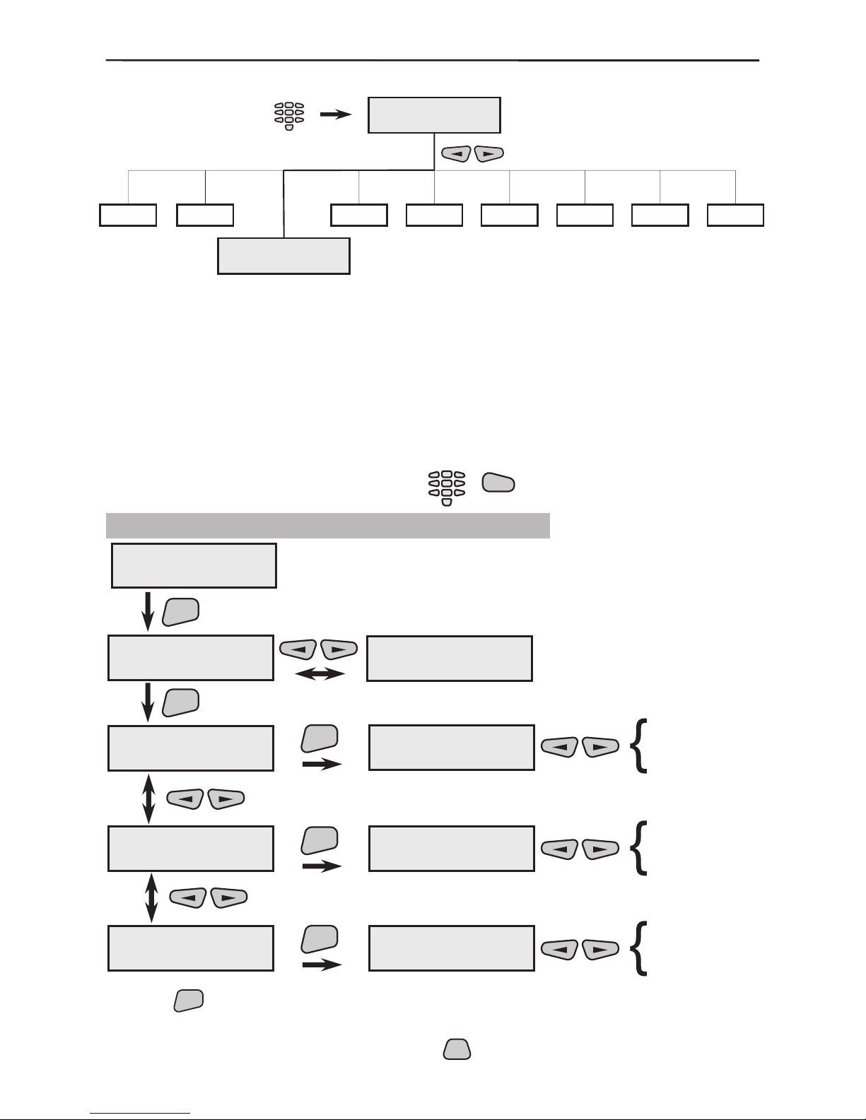
3.2 Functions Programming
The AVA Wireless System is controlled by the User with the help of Arm and Disarm functions. The system avails of six possible functions for Arming and six for Disarming. The
groups (see §3.4) to be Armed / Disarmed are programmed for every individual function,
as well as for the actions and the programmable outputs that will carry them out.
It is possible for the system to be programmed for groups only or for output activation.
Full or partial arming can be done by using the functions, as well as individual output
activation or generating of a “PANIC” message that is to be sent to a central monitoring
station.
To select the function programming menu press in succession:
3.2.1 Arming Functions Programming
Use the
ENT
button to conrm all entered data and changes.
* All active parameters in the system are marked with the “*” symbol and the
inactive - with the “-” symbol. Press the
PRG
button of the keypad to change the
parameter status of the respective submenu.
Engineer
code-7777
Engineer Menu
Engineer Menu
3)Functions
1
2
4
5
6789
3
Engineer
code-7777
3)Functions
1)ARMing
1)ARMing
function N: 06
1)ARMing
function N: 01
ENT
1)Group options
- Instant ARM
- Instant ARM
* Group 1
* Group 2
*3
-4
-5
-6
Group
Group
Group
Group
function N: 01
1)Group options
function N: 01
2)PGM action
function N: 01
3)PGM Number
ENT
ENT
ENT
no action
Set
Reset
Change
Pulse2sec.
Pulse5sec.
Pulse 10 sec.
2)PGM action
no action
no PGM selected
PGM 1
PGM 2
PGM 3
PGM 4
3)PGM Number
no PGM selected
ENT
*
Page 37

3. Programming 37
Programming is done by selecting the
PRG
button, as described
in §3 on page 20. Specify in the submenu which detector groups
are to be armed by the programmed function.
By default Function 1 has been programmed to arm Groups 1, 2 and 3 and
Function 2 – Groups 1, 2, 3, 4, 5 and 6.
When the system is armed where the Instant ARM option has been selected, the Entry/Exit type groups shall be considered of an Instant type
and entry-exit time will not start - see also §3.4.
The output action is programmed in this menu when a function
is activated.
Programme the number of the programmable output, which is to
perform the action assigned in the previous menu.
All Arming functions (1 to 6) are programmed in an analogical manner.
3.2.2 Disarming Functions Programming
Programming follows the Arming functions.
By default Function 1 has been programmed to disarm Groups 1, 2 and 3
and Function 2 – Groups 1, 2, 3, 4, 5 and 6.
Programming follows the Arming functions.
Programming follows the Arming functions.
Use the
ENT
button to conrm all entered data and changes.
2)DisARMing
function N: 01
ENT
1)Group options
* Group 1
* Group 1
*2
*3
-4
-5
-6
-
Group
Group
Group
Group
Group
Duress event
funtion N: 01
1)Group options
function N: 01
2)PGM action
function N: 01
3)PGM Number
ENT
ENT
ENT
no action
Set
Reset
Change
Pulse2sec.
Pulse5sec.
Pulse 10 sec.
2)PGM action
no action
no PGM selected
PGM 1
PGM 2
PGM 3
PGM 4
3)PGM Number
no PGM selected
3)Functions
2)DisARMing
ENT
2)DisARMing
function N: 06
1)Group options
2)PGM action
3)PGM Number
1)Group options
2)PGN action
3)PGM Number
Page 38
38 3. Programming
3.3 User Programming
The system supports 16 user codes with a 16 symbol name and parameters and one
engineer code with all programming rights. From the engineer code menu can not be
changed the User’s codes and their rights to bypass zones.
The manufacturer preset system codes are 0000 – for the Manager Code and 7777
– for the Engineer Code. Their values are automatically restored after completing a full
system reset.
To access the user programming menu press in succession:
3.3.1 Programming User Codes, Names and Attributes
The performance is as described in §3.1.2.
The menu is used to assign code owner rights where all attributes of the Manager Code are enabled by default.
* All active parameters in the system are marked with the “*” symbol and the
inactive - with the “-” symbol. Press the
PRG
button of the keypad to change the
parameter status of the respective submenu.
Engineer
code-7777
Engineer Menu
Engineer Menu
)Codes Menu4
1
2
3
5
6789
4
Engineer
code-7777
4)Codes Menu
1)User Codes
ENT
Code 01 name
1)Change name
Code 01 ****
Code 01 name
ENT
ENT
Code 02 xxxx
Code 02 name
1)Change name
Code 01 name
-
Code 01 name
2)CodeAttributes
ENT
2
5
8
0
1
3
4
6
79
2)CodeAttributes
* Manager
* Manager
* Bypass
* Log view
* Time/Date Set
* Remote Access
****
õõõõ
programmed code
free position for
new code
*
1)Change name
2)CodeAttributes
Page 39

3. Programming 39
The attributes have the following meanings:
Manager - holds permission to programme all remaining codes
Bypass - holds permission to bypass zones
Log view - holds permission to view event log-le
Time/Date Set - holds permission to set date and time
Remote Access - has enabled access to telephone line
Use the
ENT
button to conrm all entered data.
3.3.2 Changing the Engineer Code
The engineer code can be changed from the user menu. This code has no name.
If the change has been done correctly the screen will display:
Use the
CLR
button to return to the main screen of the User menu.
The screen will display already exists if any code which already exists is introduced and confirming ERROR if there are discrepancies between the initial code
introduced and the conrmation code.
In both cases the introduction should be resumed from the beginning.
4)Codes Menu
2)ChangeEngineer
ENT
4)Codes Menu
new code:[ ]
2
5
8
0
1
3
4
6
79
4)Codes Menu
confirm:[ ]
2
5
8
0
1
3
4
6
79
4)Codes Menu
code is changed
Page 40
40 3. Programming
3.4 Programming Detector Groups
The system provides exible organization of the different sensor groups which can be
Armed/Disarmed with the help of functions.
For better clarity we shall illustrate how the groups are determined with the example
given in Figure 9, page 11 in the beginning of this manual.
Example of grouping sensor areas and
programming Arm/Disarm functions:
The conguration includes:
1 control panel, 3 infrared detectors, 2 re detectors and 2 magnetic contacts.
Group areas:
GROUP 1: Rooms 2 + 3
Detectors: МС1 + МС2
Type: Entry/Exit
GROUP 2: Room 1 + Garage
Detectors: PIR1 + PIR2 + FIRE1
Type: Instant
GROUP 3: Room 4
Detectors: PIR3 + FIRE2
Type: Instant
Engineer
code- 7777
Engineer Menu
Engineer Menu
5)Group
1
2
3
4
6789
GarageRoom 1Room 2
Room 3
Room 4
GROUP 2
GROUP 1
GROUP 3
LEGEND:
Fire Detector
Magnet Contact
PIR Detector
Control Panel
PIR1PIR2
PIR3
FIRE1
FIRE2
MC1
MC2
Page 41

3. Programming 41
Programming Arm/Disarm Functions
With the help of the Arm/Disarm functions the system provides full or partial Arming/Disarming.
Arming function 1 – Arms Groups 1, 2 and 3 (full arm)
Arming function 2 – Arms Group 2 (partial arm)
Arming function 3 – Arms Groups 2 and 3 (partial arm)
Disarming function 1 – Disarms Groups 1, 2 and 3
Disarming function 2 – Disarms Group 2
Disarming function 3 – Disarms Groups 2 and 3
The programming of Arming/Disarming functions is described in §3.2.
To access the group programming menu press in succession:
The detectors can be grouped in 6 different areas and their status can be checked with
the
buttons. To programme the parameters of a group use the
ENT
button
to access the submenus and specify the type and name change.
The menu allows selection of the type of sensor groups.
The type serves to specify the kind of alarm activation:
Instant - instant activation;
Entry/Exit - activates entry-exit time;
Follow - the group is activated following an event (alarm) in
Entry/Exit group;
not used - selecting this option renders the group inactive*.
* Note: If the not used type is chosen there will be no
group status indication on the display!
By default Group 1 is programmed as Entry/Exit type, Group 2 - as Follow, and Groups 3 to 6 - as Instant. The type of all groups could be reprogrammed according to accommodate personal use of the system.
The performance is as described in §3.1.2.
Use the
ENT
button to conrm all entered data and changes.
5
Engineer
code-7777
G:01 --- Ent/Ext
Group 01 name
ENT
ENT
ENT
2
5
8
0
1
3
4
6
79
not used
Instant
Entry/Exit
Follow
G:02 --- Follow
Group 02 name
Group 01 name
1)Group Type
1)Group Type
Entry/Exit
Group 01 name
2)Change name
2)Change name
Group 01 name
-
G:06 --- Instant
Group 06 name
1)Group type
2)Change name
Page 42

42 3. Programming
3.5 Outputs Programming
In order to indicate (usually to external devices) certain system events (see Table of
events) or trouble, all programmable outputs (PGM1-PGM4) can be programmed separately from the functions. Several events can be programmed simultaneously as a “logical OR” from the programmed events will be formed.
To access the output programming menu press in succession:
Use the
buttons to select the output that has to be programmed.
Programme the events for which the output is to be activated.
Programme the trouble, for which the output is to be activated.
Programme the normal status of the output when inactive (if ac-
tivated it alternates it’s status NC/NO). By default all outputs are
programmed as NC.
Use the
ENT
button to conrm all entered data and changes.
* All active parameters in the system are marked with the “*” symbol and the
inactive - with the “-” symbol. Press the
PRG
button of the keypad to change the
parameter status of the respective submenu.
Engineer
code-7777
Engineer Menu
Engineer Menu
6)Outputs
1
2
3
4
5789
6
Engineer
code-7777
ENT
ENT
ENT
- Siren
- FIRE
- Tamper
- Panic
- Module Lost
- Medical
- full ARM
- part ARM
PGM N: 01
1)System Events
1)System Events
- Siren
6)Outputs
PGM N: 01
6)Outputs
PGM N: 04
PGM N: 01
2)SystemTroubles
2)SystemTroubles
-ÀÑ loss
-ÀÑ loss
- Main ÂÀÒÒ
- fuse
- module ÂÀÒÒ
- low temp.
- comm. ERR
- line fault
- RFinterference
ENT
PGM N: 01
3)Normal state
3)Normal state
* PGM1 NC to GND
* PGM1 NC to GND
* PGM2 NC to GND
* PGM3 Nc to GND
* PGM4 NC to GND
*
3)Normal state
1)System Events
2)SystemTroubles
*
*
Page 43

3. Programming 43
3.6 System Parameters programming
The menu allows programming of a variety of different system parameters which are
common to the system. To access the System Parameters menu select:
Use the
buttons to scroll through the different sub menus of the System Pa-
rameters.
3.6.1 Display Parameters Programming
Programme what is to be displayed on the main system screen, see
also §1.1.3. Programming is done as described in §3.
The “Chime on entry” is an option that activates several short
“beep” signals from the keyboard when an entry-exit zone device is
activated. The “display Groups” option shows all groups on the
main system screen and the system trouble in them (see Screen 1
on page 7).
Both options are preprogrammed in the system by default.
The menu allows to adjust the back light on the display. The values
are between 00 - 15, where the greater value means more brightness. The recommended values of 03 has been set by default.
Use the
ENT
button to conrm all entered data and changes.
Engineer Menu
Engineer Menu
7)System
1
2
3
4
5
689
Engineer
code-7777
7
Engineer
code-7777
ENT
ENT
ENT
* Chime on entry
* display Groups
1)LCD settings
1)Display
1)Display
* Chime on entry
7)System
1)LCD settings
1)LCD settings
2)Backlight
2)Backlight
< >:03
2
5
8
0
1
3
4
6
79
or
-
1)Display
2)Backlight
Page 44

44 3. Programming
3.6.2 Built-in Siren Parameters Programming
Menu for the events where the built-in siren of the control panel
is activated. By default the events “Alarm”, “FIRE”, “squawk
on full” (beeps in full arming) and “squawk on p a r t ”
(beeps in part arming) are programmed.
The duration of the siren signal is programmed. By default the
time is set at 2 min.
Use the
ENT
button to conrm all entered data and changes.
* All active parameters in the system are marked with the “*” symbol and the
inactive - with the “-” symbol. Press the
PRG
button of the keypad to change the
parameter status of the respective submenu.
3.6.3 Entry Time Programming
The programmed Entry Time applies to all entry-exit groups and can be within the interval of 0 - 255 seconds. By default the programmed Entry Time is 10 sec.
Use the
ENT
button to conrm the entered time.
3.6.4 Exit Time Programming
The programmed Exit Time applies to all entry-exit groups and can be within the interval
of 0 - 255 seconds. By default the programmed Exit Time is 20 sec.
Use the
ENT
button to conrm the entered time.
ENT
ENT
ENT
* Alarm
* FIRE
- Tamper
- Panic
- Module Lost
- Medical
* sqwk.on fARM
* sqwk.on pARM
2)Main Siren
1)System Events
1)System Events
* Alarm
7)System
2)Main Siren
2)Main Siren
2)Cut-Off time
2)Cut-Off time
2 minute
1 minute
2 minune
3 minute
4 minute
ENT
7)System
3)Entry Time
3)Entry time
in seconds:10
2
5
8
0
1
3
4
6
79
-
ENT
7)System
4)Exit Time
4)Exit Time
in seconds:20
2
5
8
0
1
3
4
6
79
-
*
1)System Events
2)Cut-Off time
Page 45

3. Programming 45
3.6.5 Programming Backlight Turnoff Time and Generating of an Event for Mains
Power Lost
During a main electrical power failure for a longer time than programmed, the display
back light completely turns off to save the battery. The problem is visualized by the blinking symbol
on the control panel.
In case of failure of the main power supply, the system generates an “EV_AC_LOST”
system event. It is sent to a monitoring system or by telephone line, which can be postponed in time in the interval of 0 - 255 minutes, in order to avoid indicating the problem
during short-term power failures.
The default programmed time for postponing the generation of an “EV_AC_LOST” system event is 30 minutes.
Use the
ENT
button to conrm the entered time.
3.6.6 System Options Programming
The menu allows for “single-touch button operation”, i.e. quick arming without the requirement of an user code. The messages to the communicator and the event memory
log during operation with single-touch functions are generated for user code 16 (therefore user code 16 has to be respectively programmed by assigning Arming Rights,
see AVA User Manual, User Programming).
The options “one touch menu” and “one touch ARM” have been activated by
default.
The activated option “Tamper on Lost” gives the possibility for generating a mes-
sage for open tamper-switch at lost device event. With the activated option “Tamper
disable” the system would not send messages for open tamper-switch of a device.
Use the
ENT
button to conrm the entered data and changes.
* All active parameters in the system are marked with the “*” symbol and the
inactive - with the “-” symbol. Press the
PRG
button of the keypad to change the
parameter status of the respective submenu.
3.6.7 Software Version
The system software version can be seen in the menu.
3.6.8 Language Menu
The AVA Control Panel supports different languages for the system menu. By default the
menus are in English.
Use the
ENT
button to conrm the entered language.
ENT
7)System
5)AC fault delay
5)ÀÑ fault delay
in minutes :30
2
5
8
0
1
3
4
6
79
-
* one touch menu
* one touch ARM
- Tamper on Lost
- Tamper disable
ENT
7)System
6)System options
6)System options
* one touch menu
ENT
7)System
7)Soft. Version
7)Soft. Version
ver.:ÕÕ
7)System
8)Language
8)Language
english
ENT
*
Page 46

46 3. Programming
3.7 Service Menu
The service menu is programmed and used ONLY by authorized personnel
of the producer!
3.8 Communicator (Dialer) Programming
The communicator is designed to be installed in the wireless system box and has the
following basic functions:
1. Transmits messages by telephone to the central monitoring station or to a preset
telephone number.
2. Provides remote control and system programming by computer.
3. Provides the ability to listen, talk and control the system over the telephone.
To access the menu to programme the digital communicator select:
The system allows up to six telephone numbers to be recorded, by which the system can
report a specic event. Use the buttons on the keyboard to enter the digits and letters in
all menus of the communicator and press
ENT
to conrm the introduced data.
Engineer Menu
Engineer Menu
9)Dialer
1
2
3
4
5
6
7
8
Engineer
code-7777
9
Engineer
code-7777
The communicator menus are active only when the Dialer has been properly installed and connected in the main panel box.
Page 47

3. Programming 47
3.8.1 Telephone Numbers Programming
Use the 1)Phones menu to view the different sub menus for programming the parameters of the different telephone numbers. Each telephone number is programmed
individually. The respective menus are programmed:
For telephones 1 to 6 a telephone number is assigned to dial the
user or a monitoring station. Enter digits 0÷9 and/or the letters
“P”, “T”, “D” and “0” for an interval, where the letters have the
following meanings:
“D” is a 2 second pause;
“P” means passing over to pulse dialling mode;
“T” means passing over to tone dialling mode.
Each dialling starts in tone mode.
The interval (double pressing the button “0”) deletes the unnecessary digits from the telephone number. After the communicator is reset there is no entered telephone number by default.
It is recommended that the telephone numbers be introduced to the sys-
tem last because after they are conrmed with the
ENT
button the commu-
nicator will start dialling them as is assigned in the parameters by default.
9)Dialer
1)Phones
ENT
1)Phones
Phone 01
1)Phones
Phone 06
ENT
Phone 01
1)Enter Phone
Phone 01
2)Choose Dest.
Phone 01
3)Choose Prot.
Phone 01
4)Enter ID
ENT
ENT
ENT
ENT
1)Enter Phone
-
2
5
8
0
1
3
4
6
79
2)Choose Dest.
Dest.(1-4) 01
-
or
2
5
8
0
1
3
4
6
79
3)Choose Prot.
SIA
No
SIA
ContactID
User
4)Enter ID
9999
-
2
5
8
0
1
3
4
6
79
Button
0
0 PTD
Button
0
0 BCDA EF
1)Enter Phone
Page 48

48 3. Programming
9)Dialer
2)Mess.Filters
ENT
2)Mess.Filters
Message 01
2)Mess.Filters
Message 64
ENT
Message 01
1)Destinations
ENT
1)Destinations
* Dest. 1
* Dest. 1
* Dest. 2
* Dest. 3
* Dest. 4
For telephones 1 to 6 is assigned a number for a Destination from
1 to 4 where 1 means top dialling priority and 4 is the lowest priority.
Any message (about an event) is transmitted individually to one of
the four Destinations; after it has been successfully transmitted the
telephone transmission attempts to the same Destination are terminated. By default and after reset the communicator is assigned
to Destination 1.
A protocol for data exchange is programmed for every telephone
from 1 to 6 - “SIA” or “Contact ID” for data exchange with cen-
tral monitoring station; and a “User” protocol for personal calls to
the user. The default protocol after the communicator is restarted
is “SIA”.
A 4-digit identication number of a site is programmed for every
telephone from 1 to 6 for transmitting events to the monitoring station. By quick-pressing the 0 button enter Figures 0 – 9 or the let-
ters A - F. After the communicator is reset the number is 9999.
Where a “User” protocol for sending messages has been programmed,
the identication number of the site does not need to be introduced. Its
default programmed value shall not interfere with the performance of the
communicator.
3.8.2 Event Messages Programming
From the menu 2)Mess.Filters use the buttons to select a message
from 01 to 64. These messages are transmitted to the user in case of a system event,
also see §4 Events LOG.
Select the transmission Destination (1 to 4) for every message.
After resetting the communicator, Destinations 1 and 2 are set to
transmit all events (suitable to be transmitted to the central station)
and Destinations 3 and 4 are set for the events suitable to be transmitted by user protocol (alarm events only). This means that the
telephones connecting to the Central Station are programmed as
Destinations 1 and/or 2 and the protocol “SIA” or “Contact ID”
shall be selected for them whereas the telephones for calling the
User are programmed for Destinations 3 and/or 4 via the “User”
protocol.
* All active parameters in the system are marked with the “*” symbol and the
inactive - with the “-” symbol. Press the
PRG
button of the keypad to change the
parameter status of the respective submenu.
*
2)Choose Dest.
3)Choose Prot.
4)Enter ID
1)Destinations
Page 49
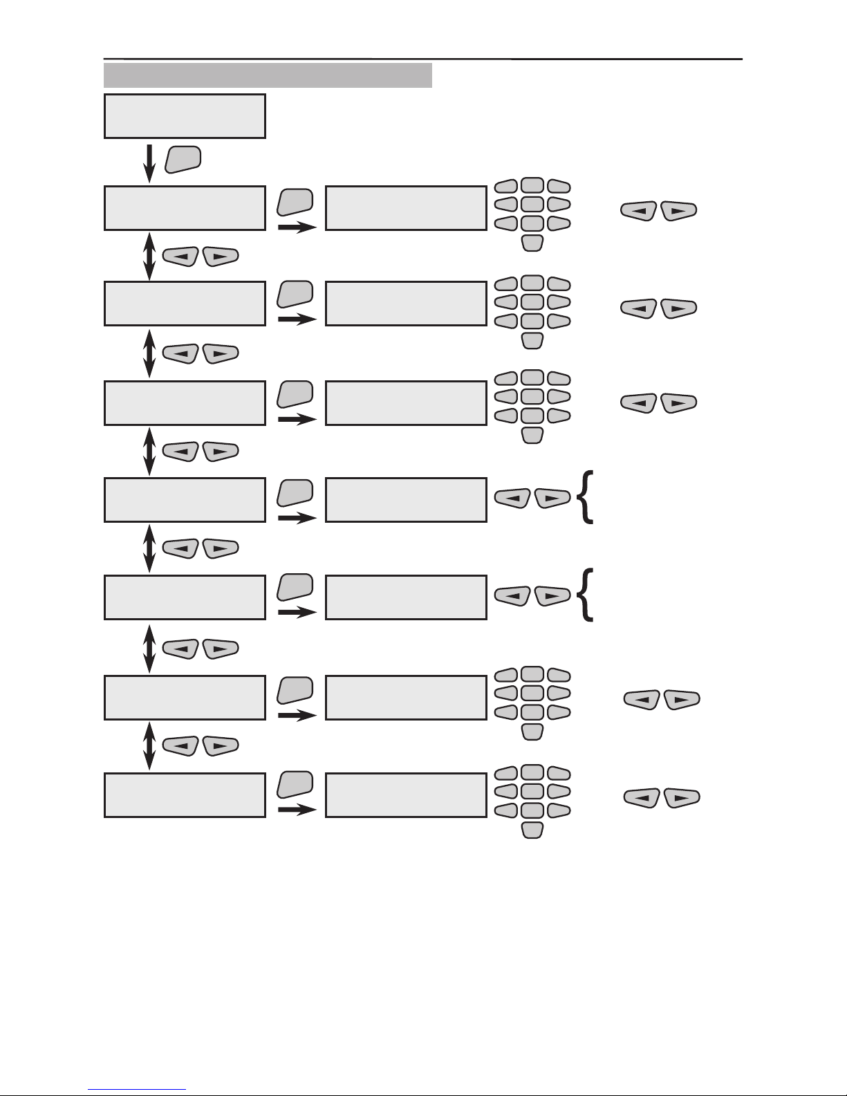
3. Programming 49
3.8.3 Dialer Properties Programming
Set the number of attempts for transmitting a message with priority to all destinations. Each message is transmitted independently to one of the four destinations, and following successful
transmission the attempts to reach the user are terminated. In
case of failure an attempt shall be made to redirect the message
to another telephone number availing of the same priority, and
so on until the number of attempts, set in the menu, is reached.
After the communicator is reset, the default preset value is 2.
9)Dialer
3)Dialer Prop
ENT
3)Dialer Prop
1)Dest Attempt
1)Dest Attempt
Count(1-9) 02
3)Dialer Prop
2)Max Attempt
3)Dialer Prop
3)Line break
3)Dialer Prop
4)Common flags
3)Dialer Prop
5)Expand SIA
ENT
ENT
ENT
ENT
2)Max Attempt
Count(1-9) 04
-
3)Line break
min(0-99) 15
-
or
2
5
8
0
1
3
4
6
79
4)Common flags
- Call Back
- Call Back
- Ans Mashine
- Wait Dialtone
- Code6Dig
5)Expand SIA
-Sia Hi Speed
3)Dialer Prop
6)Hour test
3)Dialer Prop
7)Minute test
ENT
ENT
6)Hour test
Hour(0-23)12
7)Minute test
Min(0-59)01
-
ENT
or
2
5
8
0
1
3
4
6
79
or
2
5
8
0
1
3
4
6
79
- Sia Hi Speed
- Sia Ext Area
- Sia Ext Time
- Sia Ext Date
-
or
2
5
8
0
1
3
4
6
79
or
2
5
8
0
1
3
4
6
79
-
1)Dest Attempt
*
*
Page 50

50 3. Programming
Set the maximum number of attempts to transmit an event to a
central station or to an individual user in this menu. After the communicator is reset, the default value is 4. After listing in order of
priority the 4 Destinations, the dialling attempts are renewed after
listing the 4 destinations in a priority order, set in the “Max At-
tempt” parameter is reached, by enumerating according to the
transmission priority.
Example 1:
Three telephone numbers for sending event messages are introduced in the communicator (i.e. the messages shall be sent to three separate Destinations), which are selected by different priority (preset in the 2)Destinations submenu).
The parameters “Dest Attempt” - 02 and “Max Attempt” – 04 are set. This means
that each of the telephone numbers shall be initially dialled twice and if unanswered by
the respective telephone number up to four more times.
Phone 1
Phone 2
Phone 3
Priority/
Destination
1 1 3
Under such scheme of organization the communicator shall begin to dial the preset telephone numbers according to their priority:
1
, 2 , 1 , 2 , 3 , 3
1 , 2 , 3 ,1 , 2 , 3
The rst row of attempts is dependant on the “Dest Attempt” parameter and the
second on the “Max Attempt” parameter.
NOTE: The telephone numbers 1 and 2 are with Destination 1, which means that
the messages are transmitter via SIA or ContactID protocol to a monitoring
station. The telephone number 3 is with Destination 3 which means transmitting
directly to a User by a User protocol.
Example 2:
Let us use the same example but with preset parameters of “Dest Attempt” - 04 and
“Max Attempt” - 04. This means that each of the telephone numbers shall be se-
lected initially four times depending on its priority and if unanswered by the respective
telephone number up to four more 4 times.
Under such scheme of organization the communicator shall begin to dial the preset tel-
ephone numbers according to their priority:
1
, 2 , 1 , 2 , 1 , 2 , 1 , 2 , 3 , 3 , 3 , 3
1 , 2 , 3 ,1 , 2 , 3 ,1 , 2 , 3 ,1 , 2 , 3
Example 3:
Given the preset parameters of “Dest Attempt” - 01 and “Max Attempt” - 04, the
following shall be selected in sequence:
1
, 2 , 3 ,1 , 2 , 3 ,1 , 2 , 3 ,1 , 2 , 3
The telephone number is dialled only where a number and protocol have
been set.
2)Max Attempt
Page 51

3. Programming 51
Introduce a telephone line fault warning indication delay. The
time is set in minutes. The availability of a telephone line is not
tested if the preset value is 0. After resetting the communicator
the preset default value is 15 minutes.
Set the options for the performance of the dialer in this menu.
* All active parameters in the system are marked with the
“*” symbol and the inactive - with the “-” symbol. Press
the
PRG
button of the keypad to change the parameter status
of the respective submenu.
The “Wait Dialtone” option is used to wait for the dial tone
signal before dialling a telephone.
Data can be exchanged by dialling the UDL number (up-download) from the system where a “Call Back” option has been
set.
The “Ans Mash” option has to be activated if there is a device for recording of voice messages (answering machine) connected to the telephone line after the digital communicator of
the control panel . The device (answering machine) has to be
set to answer the incoming calls at a lower number of rings
than the digital communicator of the control panel. Then the recording device (answering machine) will switch on before the
communicator of the control panel . If within a 3-minute period
there is a second incoming call the communicator will switch
on immediately.
The “Code 6 Dig” option is not in use for this software version. There are no set options following reset.
Additional alarm system transmission options using protocol
SIA have been preset in the menu. Programming is done by
pressing the
PRG
button, as described in §3.
- SIA Hi Speed - modem transmission speed to the central
station (parameter value is 110b/s if unset);
- SIA Ext Area - transmission from modier about event
group;
- SIA Ext Time - transmission from modier about hour of
event;
- SIA Ext Date - transmission from modier about date.
There are no set options following reset.
Set the hour for transmitting an automatic test to a central station. Set a number between 0 and 23. Following a system reset
the test hour will be 12.
Set the minute for transmitting an automatic test to the monitoring station. Set a number between 0 and 59. Following a system
reset the introduced minute shall be 01.
3)Line break
4)Common flags
5)Expand SIA
6)Hour test
7)Minute test
Page 52
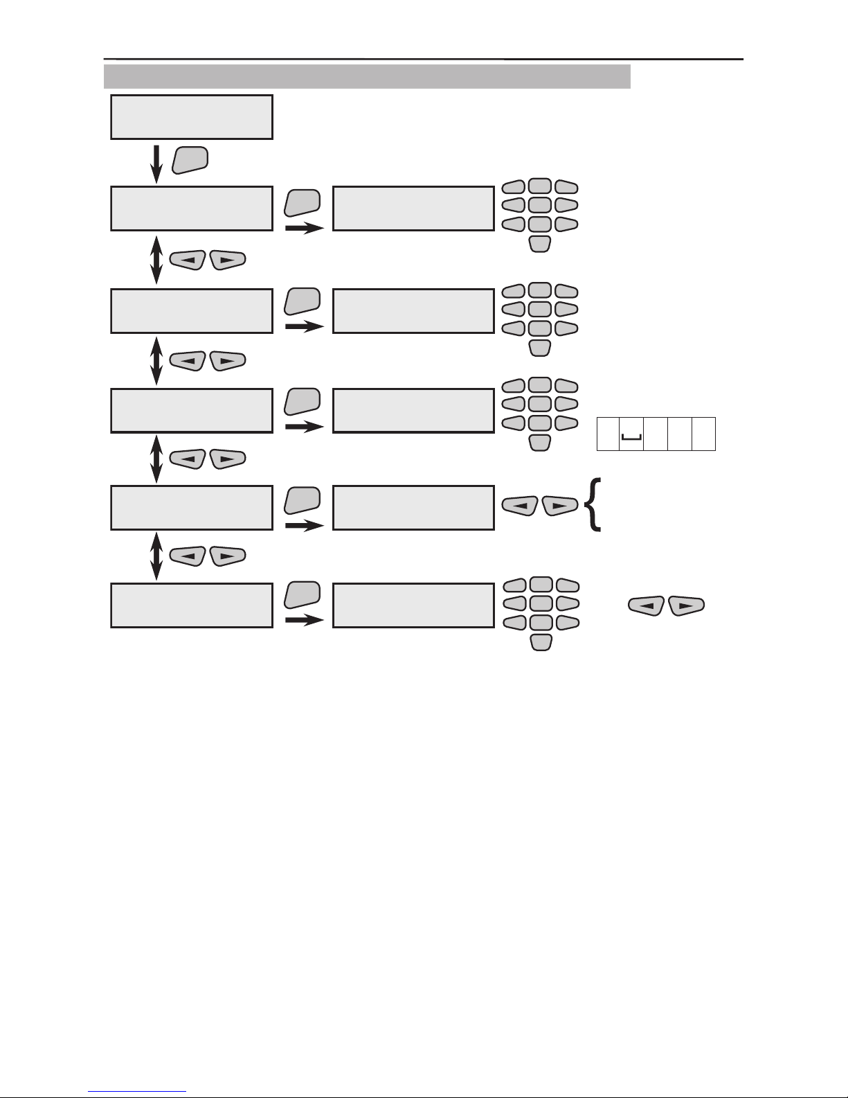
52 3. Programming
3.8.4 PC Connection Programming
Introduce the panel ID No. for data exchange (UDL). After reset,
the preset value is 1234.
Introduce the computer ID number for communicating with the
UDL. After reset, the preset value is 1234.
Introduce a UDL call-back telephone number. Introduce the
numbers 0÷9 and/or the letters “P”, “T”, “D” and “0” for an interval, where the letters have the following meanings:
“D” is a 2-second pause;
“P” means passing over to pulse dialling mode;
“T” means passing over to tone dialling mode.
Each dialling begins in tone mode.
The interval (double pressing the button “0”) deletes the unnecessary gures from the telephone number. After the communicator is reset, there will be no default introduced number.
9)Dialer
4)Udl
ENT
4)Udl
1)Id Panel
1)Id Panel
1234
4)Udl
2)Id PC
4)Udl
3)Callback Ph
4)Udl
4)Answer mode
4)Udl
5)Rings
ENT
ENT
ENT
ENT
2)Id PC
1234
-
3)Callback Ph
-
2
5
8
0
1
3
4
6
79
4)Answer mode
No Answer
No Answer
modem
DTMF cntrl
5)Rings
Count (09)07
ENT
2
5
8
0
1
3
4
6
79
2
5
8
0
1
3
4
6
79
-
or
Button
0
0 PTD
2
5
8
0
1
3
4
6
79
-
1)Id Panel
2)Id PC
3)Callback Ph
Page 53
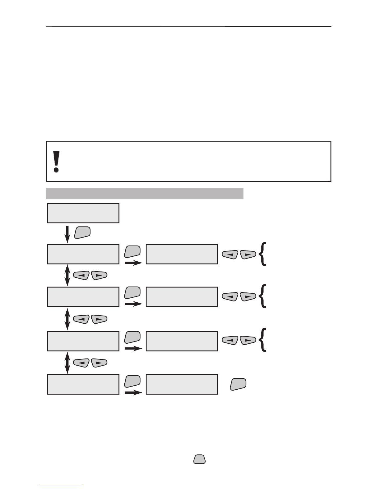
3. Programming 53
When answering the telephone select the type of signal from the
menu. The possible options are:
“Modem” - after the telephone is answered the system will expect to be connected to a UDL computer.
“DTMF cntrl” - the system will expect human control over
DTMF-tones with listening, talking and control options over the
communicator. After the system is reset there shall be no response options.
Introduce the number of telephone rings before an answer by
the system. The telephone will not be answered at the preset
value of 0. After reset the introduced value is 7.
In order to control the system via DTMF - tones, the answer function must
have been enabled, the value of the “Rings” number must be other than
“0” and the preset “DTMF cntrl” parameter must have been set in the
“Answer mode” menu.
3.8.5 Programming of Control Parameters
This menu provides an option for stopping any communication
over the telephone line and deleting the memorized events sent
to their respective destinations. By default all destinations are off
and only those shall be enabled which are expected to receive
an event message.
* All active parameters in the system are marked with the “*” symbol and the
inactive - with the “-” symbol. Press the
PRG
button of the keypad to change the
parameter status of the respective submenu.
9)Dialer
5)Manual control
ENT
5)Manual control
1)Clear buffer
1)Clear buffer
-to Dest 1
5)Manual control
2)Send Test Msg
5)Manual control
3)Pick Up
5)Manual control
4)Set default
ENT
ENT
ENT
2)Send Test Msg
*to Dest 1
3)Pick Up
DTMF cntrl
4)Set default
Continue?
modem
DTMF cntrl
ENT
-to Dest 1
2
3
4
-to Dest
-to Dest
-to Dest
*to Dest 1
2
3
4
*to Dest
*to Dest
*to Dest
ENT
*
*
4)Answer mode
5)Rings
1)Clear buffer
Page 54

54 3. Programming
The destinations to which a test message is to be sent is set in
the menu. Programming is done as described in §3. There is no
default preset Destination.
The menu sets the type of signal which is to be activated when
answering the telephone. The possible options are:
“Modem”- for computer control or for using “SIA” or “Con-
tactID” protocol;
“DTMF cntrl” – for human control (individually) and when using “User” protocol for data exchange.
The menu provides for a reset of all adjusted communicator parameters and for resetting default producer settings.
Use the
ENT
button to conrm the entered data and changes.
3.8.6 Alarm System Control by Telephone
Listening to and controlling the alarm system by telephone is done after the alarm system is dialled from a tone telephone. Following a system signal, the user must dial “*” to
interrupt it and then dial a 6 digit code. The rst four digits represent a valid user code
and the remaining two are random numbers. The code must have permitted “Remote
Access” rights – see §3.3.1 Programming User Codes, Names and Attributes.
After conrmation signal from the system, the answering machine mode is turned on.
Switching over among the various modes is done with the gures (0, 1, 2, 3). To change
over to control mode select “*”and “9”. Whilst in this state, dial the function number:
- between “001” and “006” for arming
- between “101” and “106” for disarming
To return to listening to answering machine dial “0”.
To stop the connection press “99” in listening mode.
2)Send Test Msg
3)Pick UP
4)Set default
Page 55

3. Programming 55
Algorithm for working with the communicator over the telephone
Dial the telephone number
Wait for continuous signal
from AVA system
Press once button “”*
Enter digit access code
digit valid user code
random digits
--
4- +
2
6
Received
acknowledge
signal?
No
Yes
ARM functions to
ISARM functions to
001 006
D 101 106
Button Listening to the AVA’s premises
Button Talking to the AVA’s premises
Button Listening and talking to the AVA’s premises
Button Amplified listening to the AVA’s premises
*9-Remote Arming/Disarming mode
Termination of the connection
123-
99 -
0-
Pressed buttons
or0, 1, 23?
Pressed buttons
and*9?
Pressing 99 terminates the connection.
No
Yes
Switches on respective
acoustic function
Pressed buttons
and*0?
No
Yes
No
Yes
Page 56

56 3. Programming
3.9 Maintenance Menu
This is the rst menu in the tree structure of the system software. It is in supplementary
to the engineer-installer, where the various system parameters can be veried.
* All active parameters in the system are marked with the “*” symbol and the
inactive - with the “-” symbol. Press the
PRG
button of the keypad to change the
parameter status of the respective submenu.
Engineer
code-7777
Engineer Menu
Engineer Menu
1)Maintenance
2
3
4
5
6
7
8
9
Engineer Menu
1)Maintenance
ENT
1)Maintenance
1)SystemTroubles
1)SystemTroubles
*ÀÑ loss
1)Maintenance
2)System Events
1)Maintenance
3)Group state
1)Maintenance
4)Devices state
ENT
ENT
ENT
2)System Events
* Alarm
G01 --- Ent/Ext
Group 01 name
01PIR ---#012345
PIR01
ENT
*ÀÑ loss
* main ÂÀÒÒ
* fuse
* module ÂÀÒÒ
* low temp.
* comm. ERR
* line fault
* RFinterference
* Alarm
* FIRE
* Tamper
* Panic
* Module lost
* Medical
* full ARM
* part ARM
G06 --- Instant
Group 06 name
02MC ---#123456
MC01
1)Maintenance
5)LOG
ENT
5)LOG
1)Display LOG
5)LOG
2)Clear LOG
1)Maintenance
6)Main BATT
ENT
6)Main ÂÀÒÒ
12,5V batt OK
not measured yet
12,5V batt OK
10,0V batt LOST
11,0V batt LOW
*
*
Page 57
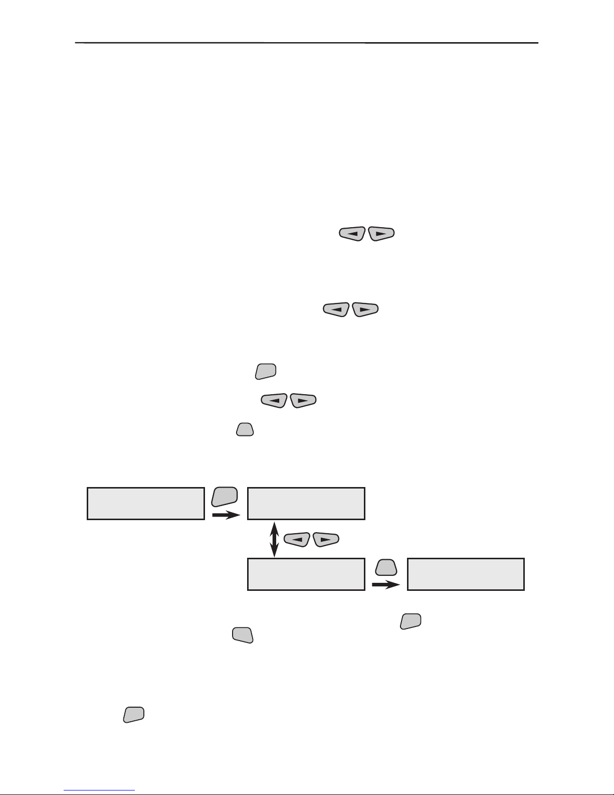
3. Programming 57
The screen lists in 1 - 2 sec. all currently available system trouble. The possible trouble can be:
AC lost - the panel does not register any power supply;
main BATT - trouble with main battery;
fuse - faulty fuse in auxiliary power supply;
module BATT - low battery level in some of the modules;
low temp. - temperature reported lower than that set;
comm. ERR - communication trouble over the phone line;
line fault - telephone line trouble;
“RFinterference” - detected radio jamming..
The screen lists the current events.
The screen displays the status of the groups in succession
every 1 sec. Use the
buttons to stop the automatic listing and to review the groups manually. This menu is
intended only for viewing the status and therefore no adjustments or changes can be made here.
The screen displays the status of the devices successively
every 1 sec. Use the
buttons to stop the automatic
listing and to view the devices manually. This menu is intended
only for viewing the status and therefore no adjustments or
changes can be made here.
Use the
ENT
button to access the menu where the events can
be indicated or deleted.
Use the buttons in the submenu to list the latest
256 events by ordinal number, hour, minute and date. Pressing
the
PRG
button on the screen will display further information
on a second screen indicating the group number and the device name where the event has occurred.
Example for LOG displaying:
The submenu provides for the event Log-le to be deleted
which is conrmed by pressing the
ENT
button. To return use
the
CLR
button.
The screen visualizes information about the battery status. The
main panel battery is measured once per minute and information is provided on the current status.
Use the
ENT
button to conrm the entered data and changes.
5)Log
1)Display Log
ENT
000 07/29 19:18
EV_PROG_ENG
PRG
G:02 Group name
D:01 Device name
001 07/29 19:18
EV_BURG_ALARM
1)SystemTroubles
2)System Events
3)Group state
4)Device state
5)LOG
6)Main BATT
1)Display L O G
2)Clear LOG
Page 58

58 5. Events LOG
Event
Number
DESCRIPTION OF THE EVENT
IN THE LOG-FILE
SIA
Protocol
ContactID
Protocol
Default programming by destinations
1 2 3 4
1 EV_ERROR
2 EV_BURG_ALARM ВА 130 * * * *
3 EV_BURG_ALARM_REST ВН 130г * *
4 EV_FIRE FA 110 * * * *
5 EV_FIRE_REST FH 110г * *
6 EV_PANIC PA 120 * * * *
7 EV_PANIC_REST PH 120г * *
8 EV_TAMPER TA 137 * * * *
9 EV_TAMPER_REST TR 137г * *
10 EV_MEDICAL MA 100 * * * *
11 EV_MEDICAL_REST MH 100г * *
12 EV_SENSOR_BPS UB 570 * *
13 EV_SENSOR_BPS_R UU 570г * *
14 EV_WATER_ALARM WA 154 * *
15 EV_WATER_ALARM_R WH 154г * *
16 EV_FIRE_BPS FB 571 * *
17 EV_FIRE_BPS_REST FU 571г * *
18 EV_HEAT_ALARM KA 158 * *
19 EV_HEAT_ALARM_R KH 158г * *
20 - 21 NOT USED
22 EV_FREEZE_ALARM ZA 159 * *
23 EV_FREEZE_ALARM_R ZH 159г * *
24 EV_DISARM_USER OP 401 * *
25 EV_DISARM_REMOTE OQ 407 * *
26 NOT USED
27 EV_ARM_USER CL 401 * *
28 EV_ARM_REMOTE CQ 401 * *
29 - 30 NOT USED
31 EV_PROG_ENG LB 627 * *
32 EV_PROG_ENG_END LX 628 * *
33 EV_DURESS HA 121 * * * *
34 EV_COMM_LINE YS 351 * *
35 EV_COMM_LINE_REST YK 351г * *
36 EV_COMM_FAIL YC 354 * *
37 EV_TEST_AUTO RP 602 * *
38 EV_TEST_MANUAL RX 601 * * * *
39 EV_FUSE YP 300 * *
40 EV_FUSE_REST YQ 300г * *
41 EV_SYSTEM_RESET YW 305 * *
42 EV_АС _LOSS AT 301 * *
43 EV_АС _REST AR 301г * *
44 EV_BAT_LOW YT 311 * *
45 EV_BAT_REST YR * *
46 NOT USED
47 EV_ExpM_TAMPER ES 341 * *
48 EV_ExpM_TAMPER_R EJ 341г * *
49 EV_RF_BATT XT 384 * *
50 EV_RF_BATT_R XR 384г * *
51 EV_RF_INTERF XQ 344 * *
52 EV_RF_INTER_R XH 344г * *
53-58 NOT USED
59 EV_ExpM_LOST EM 333 * *
60 EV_ExpM_LOST_R EN 333г * *
61 EV_CLEAN_SENSOR AS 616 * *
62 NOT USED
63 NOT USED
64 NOT USED
4.Events LOG
Page 59

5.Electrical Spesications 59
5. Electrical Specications
5.1 Electrical Specications of AVA Control Panel
Power Supply:
- Main power supply - ~230V AC ±10%, 50-60Hz
- Backup Battery - 12V, 1.2 ÷ 7Ah, Accumulator
Current Consumption (device optional):
- from 230V AC, with battery full charged ~ 40-50mA
- from 230V AC, with 0,8А charge current ~ 100mA
- from Battery without 230V AC ~ 40-140mA
(depends on the back light mode, output statuses, etc.)
Performance Duration in Case of 230V AC failure:
- with 1,2Ah Battery - minimum 12 h / maximum 30 h
- with 7Ah Battery - minimum 72 h / maximum 148 h
Maximal current at Output 1 (at U
out
= CLOSED) - 2А
At U
out
= OPEN, the output current is restricted by 1K resistor.
Maximal current at Outputs 2, 3, 4 (at U
out
= CLOSED) - 100mА
At U
out
= OPEN, the output current is restricted by 1K resistor.
Primary fuse (230V AC) - 0,315A
Battery fuse - 2А
Supplementary voltage PGM (+12V) fuse - 1A
Dimensions of the AVA Control Panel Box - 293 х 340 x 102 mm
5.2 Electrical Specications of a Repeater Module
Power Supply:
- Main power supply - ~230V AC ±10%, 50-60Hz
- Backup Battery - 12V, 1.2 ÷ 7Ah, Accumulator
Current Consumption (device optional):
- from 230V AC, with battery full charged ~ 30-40mA
- from 230V AC, with 0,8А charge current ~ 100mA
- from Battery without 230V AC ~ 30-90mA
(depends on the output statuses, etc.)
Performance Duration in Case of 230V AC failure:
- with 1,2Ah Battery - minimum 12 h / maximum 40 h
- with 7Ah Battery - minimum 72 h / maximum 148 h
Maximal current at Output 1 (at U
out
= CLOSED) - 2А
At U
out
= OPEN, the output current is restricted by 1K resistor.
Maximal current at Outputs 2, 3, 4 (at U
out
= CLOSED) - 100mА
At U
out
= OPEN, the output current is restricted by 1K resistor.
Primary fuse (230V AC) - 0,315A
Battery fuse - 2А
Supplementary voltage PGM (+12V) fuse - 1A
Dimensions of a Repeater Module Box - 293 х 340 x 102 mm
Page 60

60 5.Electrical Specications
5.3 Other Specifications
Expected Battery Life for Wireless Devices:
- Infrared detector - up to 2 years
- Magnetic contact - up to 3 years
- Remote control - up to 3 years (at 40-50 activations per a day)
- Outdoor siren - up to 4 years
- Wireless keyboard - up to 6 months without voice guide messages
- up to 4 months with voice guide messages
Further Information for all wireless devices:
- Working frequency - 868Mhz ISM band
- Standards - ETSI 300 220; EN 60950; EN 50130-4
- Radio range - up to 35m in a typical residential environment
(depending on the type of the building construc
tion and the size of the premises)
- Ambient temperature - +5 - +50°С
6. Spare Parts Kit
1. Resistor 1КΩ ±5%, 0,25W - 4 pcs
2. Resistor 2,2КΩ ±5%, 0,25W - 2 pcs
3. Fuse, slow type, 0,315А - 1 piece
4. Taping screw 2,9х13 cross slot - 2 pcs
5. Round-top screw М3х16 cross slot - 2 pcs
6. Nut М3 - 2 pcs
7. Jumper - 1 piece (on the PCB of control panel)
8. APPENDIX: General Structure of the System Menus
Page 61

7. Declaration of Conformity 61
7. Declaration of Conformity
Page 62

62
NOTES
Page 63

63
GUARANTEE
During the guarantee period the manufacturer shall, at its sole discretion, replace or repair any
defective product when it is returned to the factory. All parts replaced and/or repaired shall be
covered for the remainder of the original guarantee, or for ninety (90) days, whichever period is
longer. The original purchaser shall immediately send manufacturer a written notice of the defective
parts or workmanship, which written notice must in all cases be received prior to expiry of the
guarantee.
INTERNATIONAL GUARANTEE
Foreign customers shall enjoy the same guarantee rights as those enjoyed by any customer in
Bulgaria, except that manufacturer shall not be liable for any related customs duties, taxes or VAT,
which may be payable.
GUARANTEE PROCEDURE
This guarantee will be granted when the appliance in question is returned. The manufacturer shall
accept no product whatsoever, of which no prior notice has been received.
CONDITIONS FOR WAIVING THE GUARANTEE
This guarantee shall apply to defects in products resulting only from improper materials or
workmanship, related to its normal use. It shall not cover:
§ Damages resulting from improper transportation and handling;
§ Damages caused by natural calamities, such as re, oods, storms, earthquakes or lightning;
§ Damages caused by incorrect voltage, accidental breakage or water; beyond the control of the
manufacturer;
§ Damages caused by unauthorized system incorporation, changes, modications or surrounding
objects;
§ Damages caused by peripheral appliances unless such peripheral appliances have been supplied
by the manufacturer;
§ Defects caused by inappropriate surrounding of installed products;
§ Damages caused by failure to use the product for its normal purpose;
Damages caused by improper maintenance;
§ Damages resulting from any other cause, bad maintenance or product misuse.
In the case of a reasonable number of unsuccessful attempts to repair the product, covered by
this guarantee, the manufacturer’s liability shall be limited to the replacement of the product as the
sole compensation for breach of the guarantee. Under no circumstances shall the manufacturer be
liable for any special, accidental or consequential damages, on the grounds of breach of guarantee,
breach of agreement, negligence, or any other legal notion.
WAIVER
This Guarantee shall contain the entire guarantee and shall be prevailing over any and all other
guarantees, explicit or implicit (including any implicit guarantees on behalf of the dealer, or
adaptability to specic purposes), and over any other responsibilities or liabilities on behalf of the
manufacturer. The manufacturer does neither agree, nor empower, any person, acting on his own
behalf, to modify or alter this Guarantee, nor to replace it with another guarantee, or another liability
with regard to this product.
UNWARRANTED SERVICES
The manufacturer shall repair or replace unwarranted products, which have been returned to its
factory, at its sole discretion under the conditions below. The manufacturer shall accept no products
for which no prior notice has been received.
The products, which the manufacturer deems repairable, will be repaired and returned. The
manufacturer has prepared a price list and those products, which can be repaired, shall be paid for
every repaired appliance.
The closest equivalent product, available at the time, shall replace the products manufacturer
deems un-repairable. The current market price shall be charged for every replaced product.
Page 64

18020508, Rev F
www.teletek-electronics.com
Address: 14А Srebarna Str., 1407 Soa, Bulgaria
Tel.: (+359 2) 9694 700, Fax: (+359 2) 962 52 13
e-mail: info@teletek-electronics.bg
 Loading...