

Page 1
DHD-1000
MPEG4 HD DECODER
MPEG4 system with IP input
Technical documentation / User guide
Teletechnika Ltd.
5th Edition / 6th November 2012
Page 2
2
General description
The MPEG-2 compression that brought a revolutionary advance in the transmission of
picture and sound, by today was superseded by the MPEG-4 compression technique. On the
customers’ intensive demand Teletechnika developed the new generation of its decoders, the
MPEG4 (H.264) HD DECODER. The equipment allows the receiving of Single Program
Transport Stream and after decompressing forwards the video and audio content to the analog
video- a nd aud io out puts a nd digital SD I output with embedded audio using eit her M PEG-2 or
H.264 MPEG-4 PART 10 decompression. This version of the equipment contains a 100 Base-T
Ethernet (UDP/IP) connector.
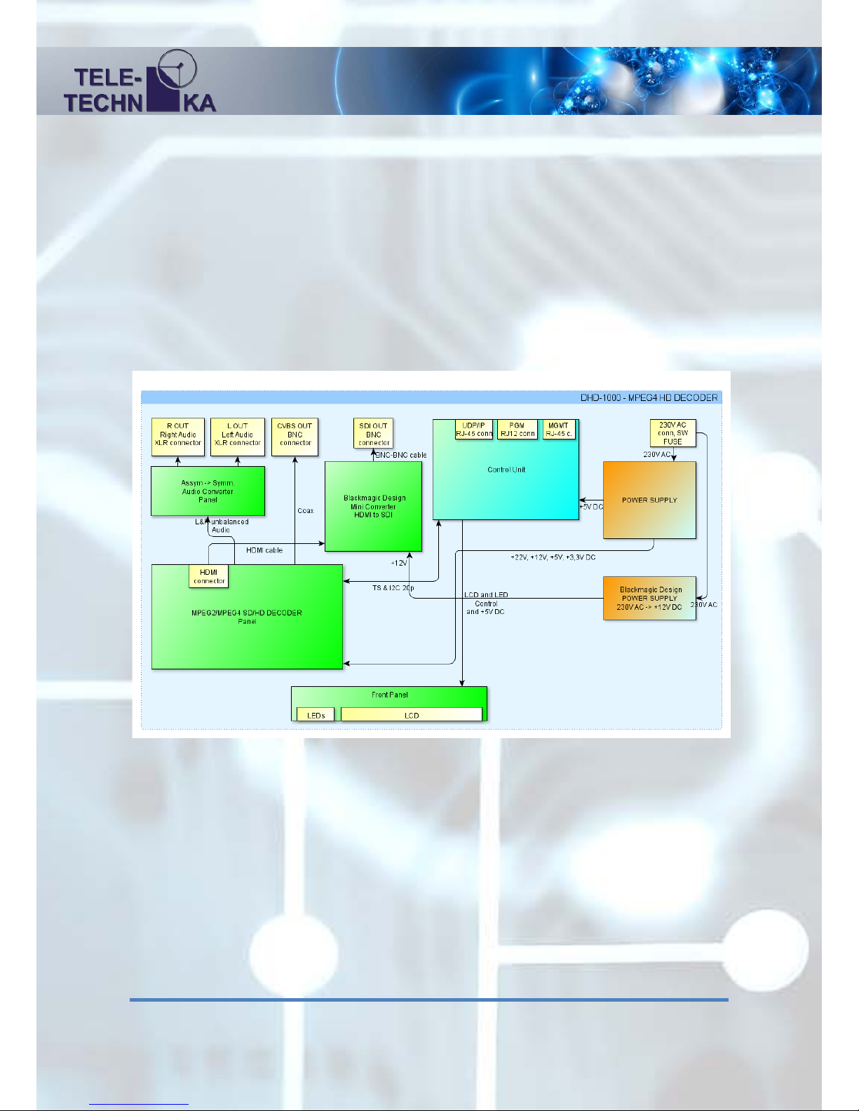
Structure
Features
• Powered by 230V AC mains voltage
• Unicast/Multicast UD P /IP input 100 Base-T ETH
• Separated management port for configuration
• Easy configuration in web browser
• MPEG2 SD, MPEG2 HD, H.264/AVC SD, H.264/AVC HD decoding
• Video Resolution: 720x480i, 720x480p, 720x576i, 720x576i, 1280x720p, 1920x1080i
• Aspect ratio: 16:9, 4:3 LetterBox, 4:3 PanScan
• Analog SD CVBS video output
• Analog stereo symmetric audio outputs (left and right channel XLR conn.-s)
• Digit al video output: SDI (with embedded audio)
• Informative, wide display
• Low power consumption
Page 3
3
Mechanical parameters, operation
The height of the encoder is 1 unit (1U) with 19’’ width and is supplied with standard
power cable.
In case of rack-mounted usage, the operator should take care of the proper airflow and
ventilation! Do not cover the case because it could cause overheating!
Hardware structure
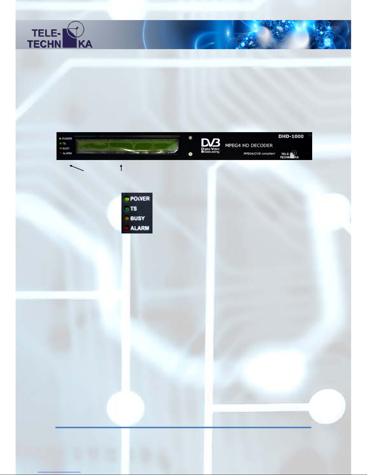
Front Panel:
State indicator LEDs LCD
State indicator LEDs: Power OK
TS proper
Decoder is busy, boot procedure
Serious internal problem
LCD:
2 line 40 character alphanumerical display, representing the state of the equipment on 6 pages:
1
st
page:
TS MAC Address: The MAC address of the UDP/IP marked ETH port
TS IP:Port: The IP address of the UDP/IP marked port separated by a colon is
the port
2
nd
page:
Multicast MAC Address: The MAC Address of the multicast receiving in hexadecimal
format
Multicast IP Address: The IP address of multicast receiving
Page 4

4
3
rd
page:
Streaming mode: No Rx (Idle): No TS receiving, waiting mode
Unicast UDP TS Rx: TS receiving in unicast mode
Multicast UDP TS Rx: TS receiving in multicast mode
Nr of TS packets:
Packet size (TS UDP packet frame number): 1 ... 7 in
parentheses is the size in bytes
4
th
page:
MGMT IP: The IP address of the configuration port.
MASK: The network mask of the configuration port.
5
th
page:
MGMT Gateway: The Gateway IP address of the configuration port.
MGMT MAC address: The factory constant MAC address of the configuration port in
hexadecimal format.
6
th
page:
TRAP IP Address: SNMP trap destination IP address which to the equipment throws
the alarm traps. (In future feature)
TRAP server is: OFFLINE / ONLINE: The Encoder can ping the server or not.
Page 5
5
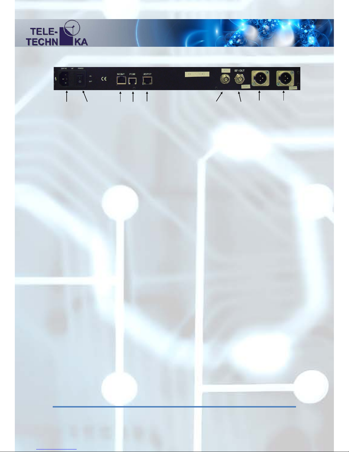
Rear Panel
230V AC: 230V power connector (cable included)
1AT: 1 Amper ’T’ type fuse, removable
POWER: Supply switch
MGMT: Management 10/100 Base-T Ethernet Port for configuration
PGM: Programmer connector just for service purposes
UDP/IP: 100 Base-T Ethernet port for TS receiving in UDP/IP packets
SDI OUT: Serial Digital Interface output BNC connector
CVBS OUT: Analog SD CVBS video output BNC connector
L OUT: Analog symetrical au d io output le ft XLR connector
R OUT: Analog symetrical audio output right XLR connector
230V AC POWER MGMT PGM UDP/IP CVBS OUT SDI OUT L OUT R OUT
1AT
Page 6

6
User manual
The equipment could be started by turning the power switch ON, located bes ide power
connector. Af ter the turn on, the PO WER LED starts to light in case of fau ltless functio n. After
the start the decoder writes to the LCD the following label: ‘ Teletechnika Ltd. ‘,
‘ DHD-1000 MPEG4 HD DECODER ‘. The BUSY LED
indicates t he boo t process.
This takes 2-3 seconds. Then, the previously described information displayed on the display.
Settings
The settings of the equipment only could be done via the MGMT connector. If there is
only a cable between the equipment end the computer it must be a crosslink type, otherwise e.g.
with a switch or router, the type of the used cable is not important.
To operate and reach th e Decoder with our PC it has to be set into t he same IP address
range as the equipment. The IP address of the equipment is on the 4th page of LCD. T he fact ory
IP address is ‘192.168.1.151’ with ‘255.255.255.0’ subnet mask.
Page 7
7
Web surface
The general and IP settings of the equipment can be reached via our PC’s browser. Type
the IP address into t he b rowser’ s hea ding a nd p r e s s ent e r . The device supports the Firefox and the
Internet Exp lorer browsers. One device at a time only one connection can connect to other open
browser connection is possible only if the channel is released. After we turn on or restart the
device must waiting about 30 to 40 seconds to boot meanwhile all parameters are not fully
available. The control port of unit is the 10001 on which the web browser connects to. The
appropriate use must b e installed t he Ad ob e Flash Player in the browser which is used. If Flash is
not installed t hen f or Fir efox the attached 'Adobe Fl ash Pl ayer Inst all er for Firefox’, for Internet
Explorer the 'Adobe Flash Player Installer for IE' application can be used.
At first an username / password window will appear. In factory settings there are not
Username or Pass word. Please keep them clear a nd press Enter. After the first login every user
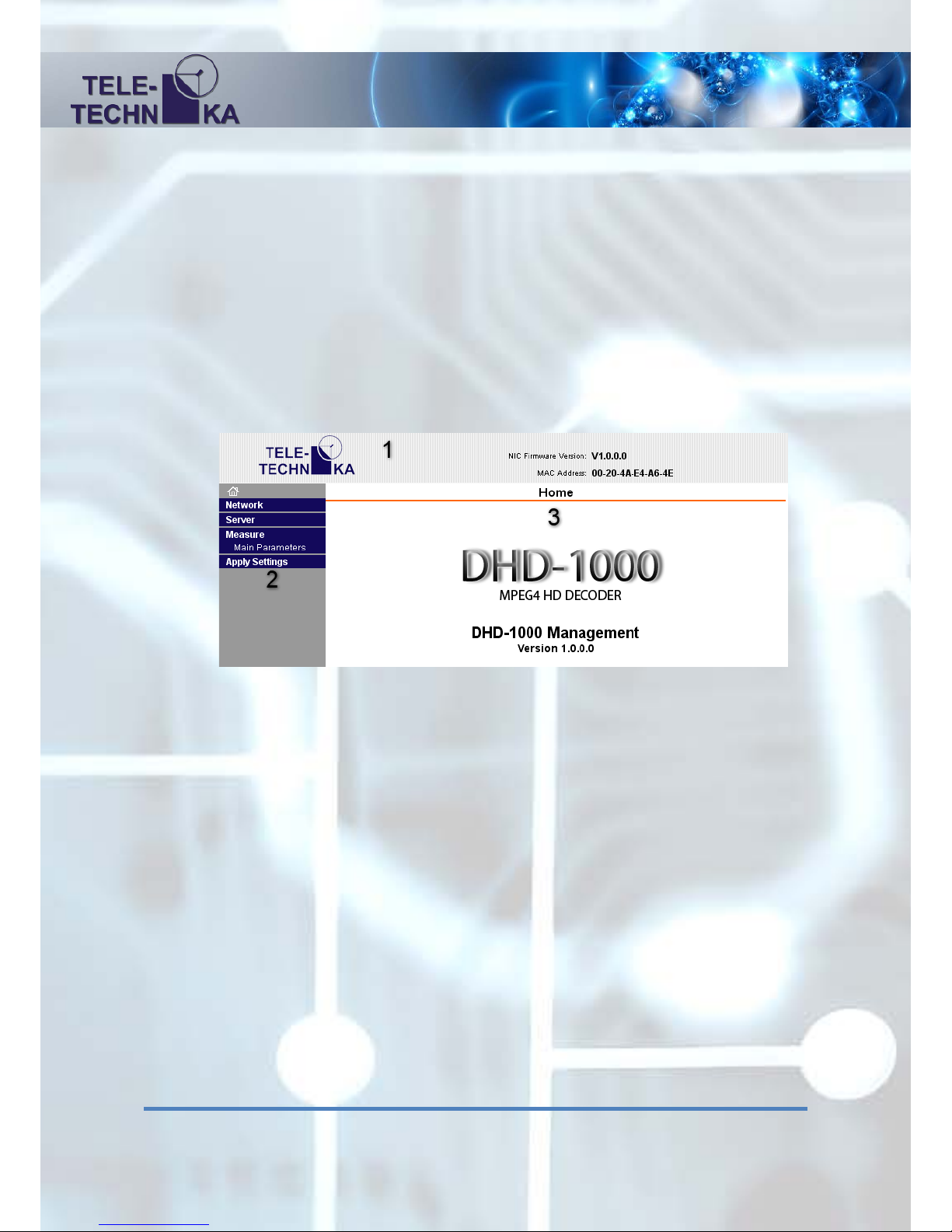
can change the Username and the Password. After logging in we can see the following web page:
Parts of the page:
1. Header:
Teletechnika official webpage can be reached by clicking the Teletechnika logo at the left
corner.
In the line beginning with ‘NIC’ is the detailed version number of the used firmware.
After in the line beginning with ‘MAC’ we can see the equipment’s MAC address.
2. Menu bar (left):
House icon: Home page
Network: Network Settings
Server: Server Settings
Measure / Main parameters: Measured- and settable parameters of the equipment
Apply Settings: Save the Network and Server settings
3. Content page:
Page of the currently used menu point. Reset this push the H ome icon and see the name
and version number of the currently used equipment.
Page 8
8
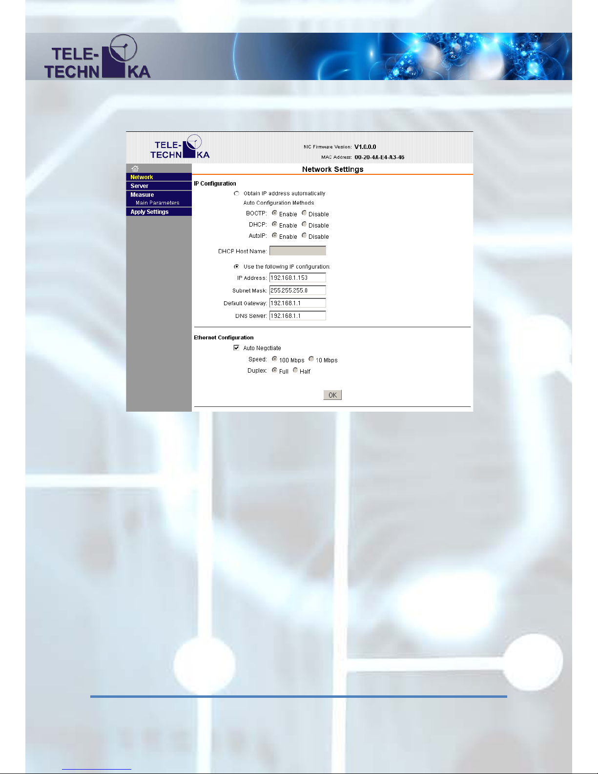
Network Settings
IP Configuration
Obtain IP address automatically:
DHCP: automatic IP settings from the used DHCP server
Use the following IP configuration:
Manu a l IP ne t wor k se t t i n g s:
IP Address: IP address of the equipment’s MGMT port
Subnet Mask: subnet mask of the equipment’s MGMT port
Default Gateway: default MGMT gateway
DNS Server: a DNS server’s address (not used)
Page 9

9
Ethernet Configuration
(These set tings should not be c han ged!)
Auto Negotiate: Che ckb ox f or au tomatic ne got ia tion
Speed: If Auto Negotiate is not checked give the parameters of the used network
10 or 100 Mbps
Duplex: Duplex- or hal f-duplex mode of the two way communication
OK: Prepare for sending the network settings
(if it is done it is marked with ‘DONE !’ line)
The option to apply settings in the Settings menu, you must click Apply.
Server Settings
Telnet/Web manager Password: Set the password for entering to the web surface
Retype Password: The password again for checking
Page 10

10
We couldn’t give user name therefore by the login always keep it the user name field empty.
The password can b e up to 4 digits. Note the password you specified, because without a password
reset operation is not possible without knowing the password.
Advanced
ARP Cache Timeout (secs): The timeout of the address resolution in seconds.
TCP Keepalive (secs): Alive hold time of the TCP connection in seconds.
Monitor Mode @ Bootup: Internal service mode enable / disable.
CPU Performance Mode: The internal CPU Performance mode, you should be high.
HTTP Server Port: The embedded web server port. Default: 80
MTU Size: Maximum packet size.
OK: On the Server Settings page Preparing to send (if the preparation has been 'Done!' Is
shown in t he tab). The option to apply settings i n t he Settings menu, you must click Apply.
Page 11
11
Measure / Main parameters:
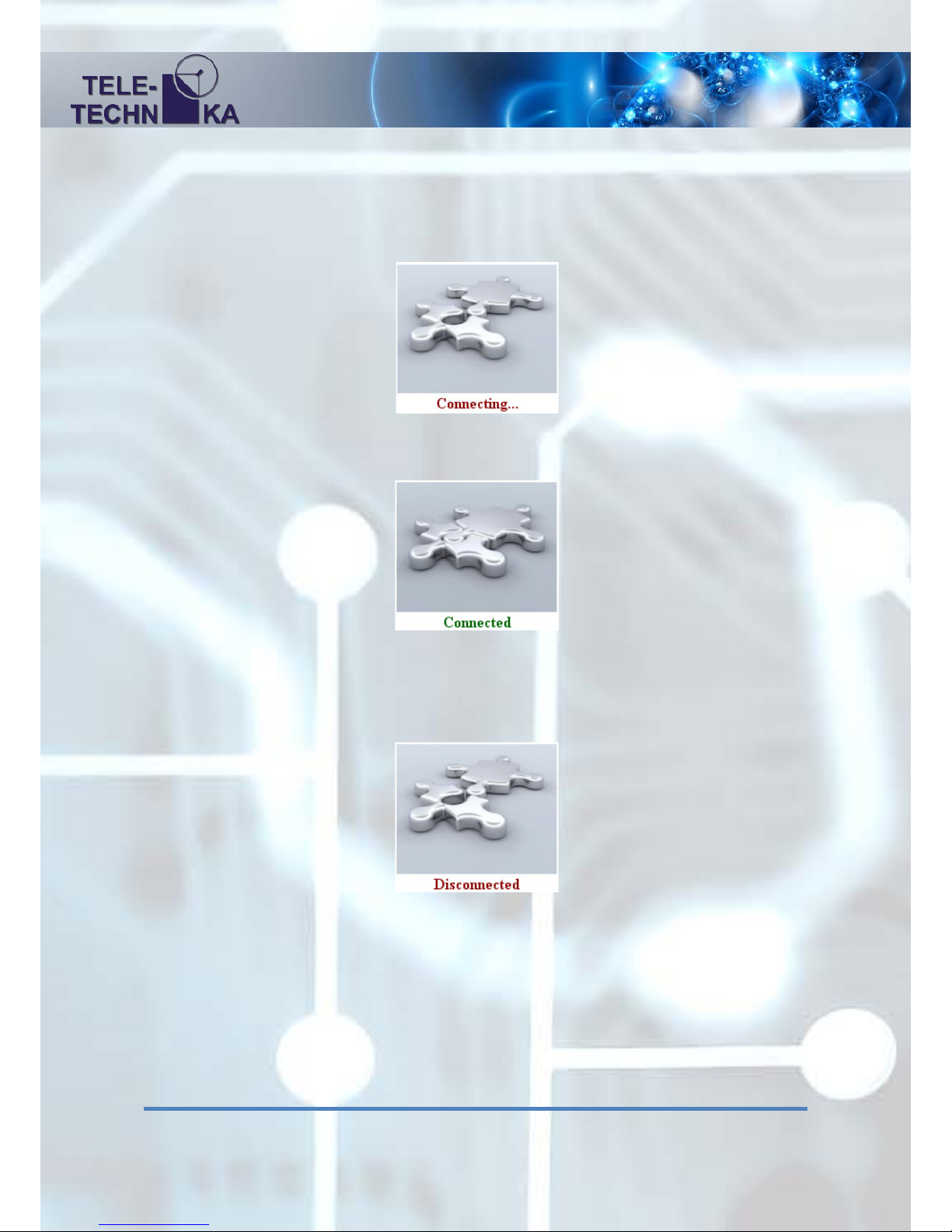
Clicking this menu item in the web browser connects to the Encoder’s 10001 control TCP port.
The process of connecting a disconnected puzzle icon and the 'Connecting ...' label is marked:
If the connection is successfully a connected puzzle and a ’Connected’ label is displayed:
If yo u lose the co nnection with the device a disconnected puzzle again a ‘Disconnected’ label is
displayed:
If you ha ve a physical relationship exists and st ill get Disconnected appears, make sure t hat only
one browser is opened and the de vice is not busy on the TCP socket port, as well as to ge t to the
10001 port o n the device. I f a ll t h e conditions are now in terms of t he ne twor k device port access
control and st ill get disconnected inscription try to reconnect it click to another menu and t hen
come back. Make sure that Internet Ex plorer is used, do not open a b row ser and a few s heets of
the same Decoder device.
Page 12
12
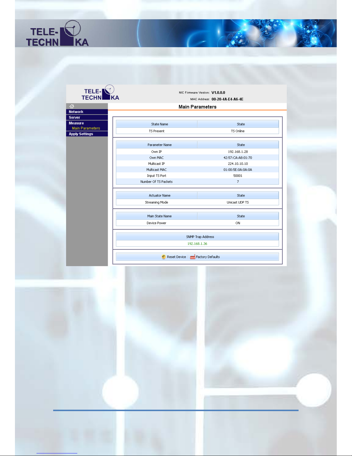
After a success ful c on nection to the content page, and configured t he device status parameter s ar e
displayed:
The interface works: data query page whe n you open alwa ys hap pe ns, and it can be set to double
click on the desired field and press Enter, and rewrite the content fix it, you can return with
Escape. The measured information page is constantly updated each second.
Status field:
This se ct ion s how s the measur ed parameters. The le ft side shows t he name of the param eter. On
the right side is the parameter.
TS Present: ‘TS Online’: The received TS is present
’TS Offline’ The received TS is not present
Page 13

13
Settings field:
In th is section can be set the par ameters. The left s ide shows the name of the parameter. O n the
right side can be change any parameter. In tooltip we can see the additional information about the
unit and the adjustable rate.
Own IP: The IP address of the UDP/IP marked port
Own MAC: The MAC address of the UDP/IP marked port, use cap ital letters
only.
Multicast IP: The multicast IP address of multicast receiving
Multicast MAC: The MAC Address of multicast receiving, use capital letters only.
Input TS Port: The received TS Port.
Nr of TS Packets:
Packet size (TS UDP packet frame number): 1 ... 7
Streaming mode: Idle: No TS receiving, waiting mode
Unicast UDP TS: TS receiving in unicast mode
Multicast UDP TS: TS receiving in multicast mode
SNMP Trap Address: The destination IP Address of the SNMP traps.
If the IP address is green it m eans t hat t he 'Trap Server Online' as
the quick t i p shows. If it is red then the first server does n ot s e e the
device ('Trap Server Offline').
Reset Device: The device performs full reset
Factory Defaults: Restore factory settings and reboot
 Loading...