

Page 1
pg. 1
TX 916
LOOP a LINE
Operator’s Manual
Page 2
pg. 2
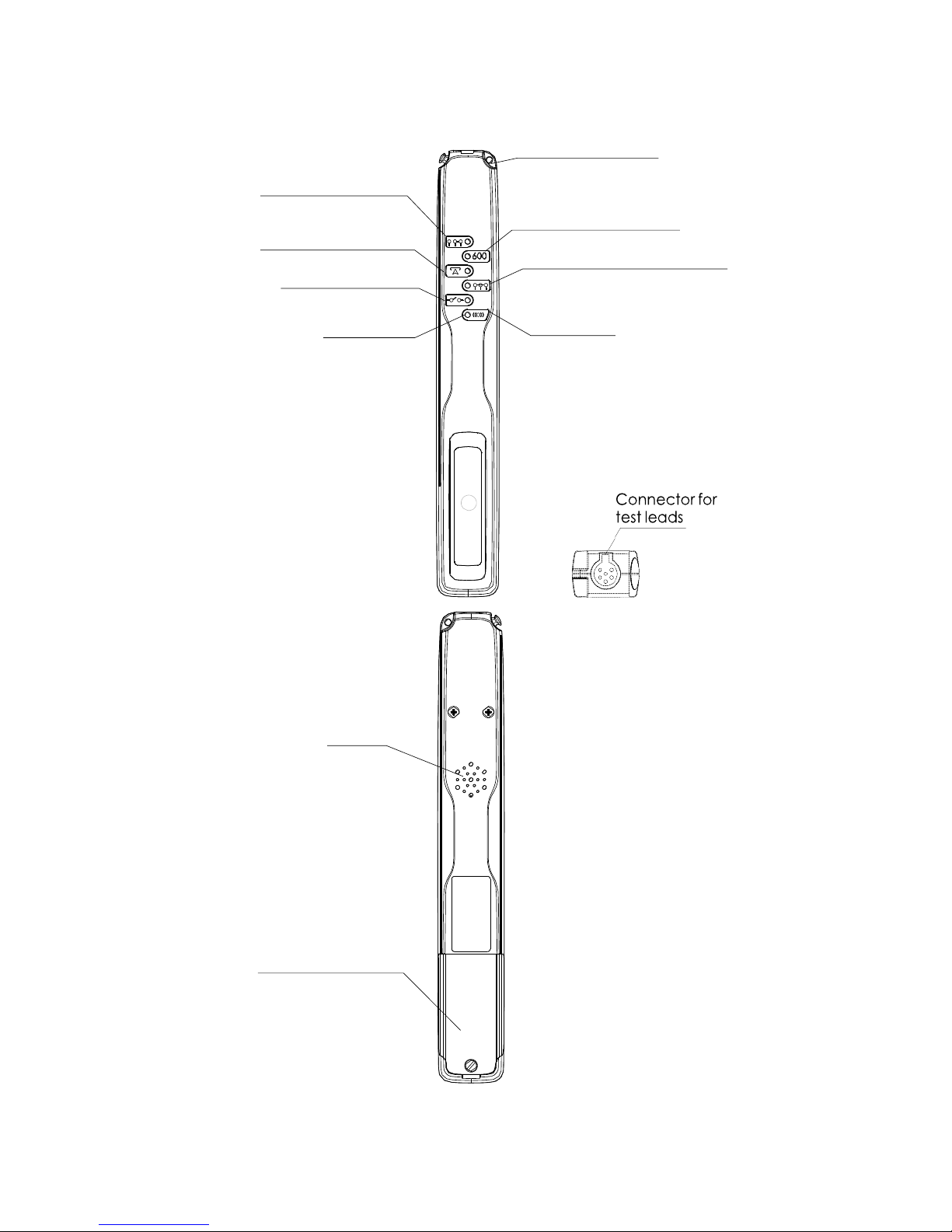
1. PHYSICAL DESCRIPTION
Hole for carry lead
Short circuit without
white wire
Connect to Exchange
mode
Quiet Line - 600
Ω
Termination mode
Short circuit with white wire
Open circuit mode
Light (LEDx6)
Tone mode
Speaker
Battery
Compartment
Figure 1-1 Oscillator
(a) FRONT VIEW
(b) REAR VIEW
(c) TOP VIEW
Page 3
pg. 3
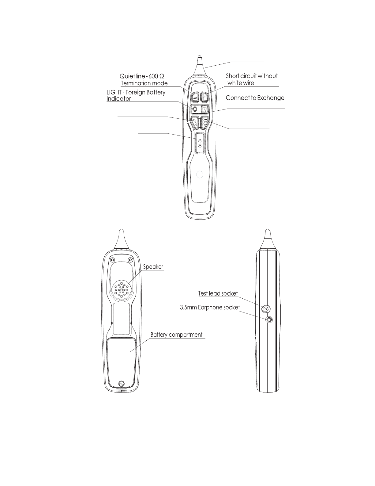
mode
Figure 1-2 Probe
(a) FRONT VIEW
(b) REAR VIEW
(c) SIDE VIEW
Probe Tip
Open circuit mode
Tone mode
Short circuit with
white wire
Page 4

pg. 4
TABLE of CONTENTS
1. PHYSICAL DESCRIPTION ...............................................2
2. SAFETY INFORMATION ..................................................5
3. INTRODUCTION................................................................7
3.1. BATTERY REPLACEMENT ....................................7
3.2. TEST LEADS.............................................................7
4. OSCILLATOR OPERATION .............................................8
4.1. OSCILLATOR POWER UP ......................................8
4.2. OSCILLATOR POWER OFF ....................................8
4.3. CABLE SHORT CIRCUIT DETECTION .................8
4.4. OSCILLATOR MODES ............................................9
5. PROBE OPERATION ....................................................... 11
5.1. SIGNAL TRACING ................................................. 11
5.2. MODE SELECTION ................................................ 11
5.3. TONES ..................................................................... 11
5.4. CONNECTED TO EXCHANGE ............................. 12
5.5. AUDIO BATTERY LEVEL INDICATOR .............. 12
6. LINE TESTS ...................................................................... 12
6.1. PAIR IDENTIFICATION ........................................ 12
6.2. CHECK FOR BALANCED PAIR ........................... 13
6.3. FAULT LOCATION ................................................ 13
Two Wire Test ........................................... 13
Three Wire Test ......................................... 14
Pulse Echo Test (PET/TDR) ...................... 14
7. SPECIFICATIONS ............................................................ 15
7.1. OSCILLATOR ......................................................... 15
7.2. PROBE ..................................................................... 15
8. WARRANTY ..................................................................... 16
Page 5

pg. 5
2. SAFETY INFORMATION
To avoid injury read “Safety Information” and
“Warnings and Precautions” before using this
instrument
Safe Working Practices
Review the safety information and adhere to the safe working
practices described in this manual and elsewhere.
Protection may be impaired if the instruments are used for purposes
other than described in this manual.
The symbols used on the instrument and in this manual are:
Safety Information Warning,
Refer to Manual
Conforms to European Union
Directives
Do not dispose of in general
domestic waste. Refer to local
authorities for direction.
Warnings and Precautions
To avoid possible electric shock or personal injury, and to avoid
possible damage to the instrument or to the equipment under test,
adhere to the following practices:
This equipment is to be used by trained technicians only. Use
caution when using this equipment. Voltages in excess of 30Vac,
42Vpeak or 60Vdc may be present on lines being tested. These
voltages pose a potential shock hazard.
Before using the equipment inspect the case. Do not use the
equipment if it is damaged. Look for cracks in the case or missing
parts. Pay particular attention to the insulation around the
connectors.
Inspect the test leads for damaged insulation or exposed metal.
Check the test leads for continuity. Replace damaged test leads
before using the equipment.
Do not use the equipment if it operates abnormally. Protection
may be impaired. When in doubt have the equipment serviced.
Do not apply more than the rated voltages to the equipment.
Use the correct connections and functions for your measurements.
Page 6

pg. 6
Take extra care when Insulation Resistance is being measured.
There may be voltage applied to the line as high as 500 Vdc.
Ensure you warn others when insulation Resistance is measured.
Ensure that equipment is removed from the line and the test leads
are disconnected before opening the case. Do not operate the
equipment with the case open.
Use only 9V alkaline batteries. Ensure the battery is installed
correctly.
Replace the battery as soon as BATTERY FLAT is indicated.
Remove the batteries if they are worn out or before storing your
device; they can become hot and cause burns.
Always remove old, weak or worn-out batteries promptly and
recycle or dispose of them in accordance with Local and National
Disposal Regulations.
If a battery leaks, remove it, taking care to keep the leaked fluid
from touching the skin or clothes. If fluid from the battery comes
into contact with skin or clothes, flush skin with water
immediately. Before inserting new batteries, thoroughly clean the
battery compartment with a damp paper towel or follow the battery
manufacturer’s recommendations for clean-up.
Breaking electrical connections may generate sparks. This
instrument is not to be used in areas in which flammable gases
exist, or may exist.
Disconnect earphones before connecting probe test leads to the
line.
TX916 is suitable for telecommunications lines and is not rated for
Mains use (>220Vac).
This equipment must not be connected to mains supply circuits.
Do not apply more than the rated voltages to the equipment.
When connecting the test clips be sure to keep your fingers away
from potentially live metal parts.
Disconnect test leads before opening battery compartment. Do not
operate the equipment with the battery cover removed.
Clean only with a damp cloth and detergent. Do not immerse in
water.
To protect from electrical shock, only use the test leads provided.
Do not use this device during electrical storms.
Page 7

pg. 7
3. INTRODUCTION
Teletech’s TX916 Loop-a-Line consists of two battery operated
devices known as the PROBE and the OSCILLATOR. Together
these devices are used by the communication technician to aid in
telephone installation and cable fault location and repair.
A communication technician can work unassisted by remotely
controlling an OSCILLATOR (located at the exchange MDF or
street cabinet) from a PROBE located on the same line up to 20km
away. This eliminates multiple journeys along the cable path and
dramatically cuts repair and installation costs.
Operating modes:
• Pair identification
• Disconnect/connect service to the exchange
• Open circuit pair
• Short circuit pair (with or without white wire)
• Insert 600 Ω line termination.
When a Loop-a-Line is used in conjunction with a Resistance
Bridge or TDR instrument; loop, insulation resistance, resistance
balance measurements and fault locating can be performed.
3.1. BATTERY REPLACEMENT
Both devices are powered by a 9 V alkaline battery (IEC 6LR61)
which can be inserted or removed by removing the battery lid on the
rear of the device using a flat head screw driver. Orient the battery
according to the polarity diagram within the battery compartment.
WARNING: Disconnect all test leads before removing the
battery lid to avoid possible connection to high voltages
sometimes present on telephone lines.
3.2. TEST LEADS
The OSCILLATOR and PROBE each have their own test leads
which are inserted into their sockets (see Figure 1-1).
Next to the PROBE’s test connector (see Figure 1-2) is a 3.5mm
audio jack that allows earphones to be inserted and is useful when
performing Pair Identification in noisy environments.
WARNING: Due to large voltage spikes sometimes
present on telephone lines, don’t insert the earphones
when the PROBE’s test leads are connected to the line.
Page 8
pg. 8
4. OSCILLATOR OPERATION
4.1. OSCILLATOR POWER UP
Inserting the test lead into to the OSCILLATOR’s socket initiates
the OSCILLATOR power up cycle.
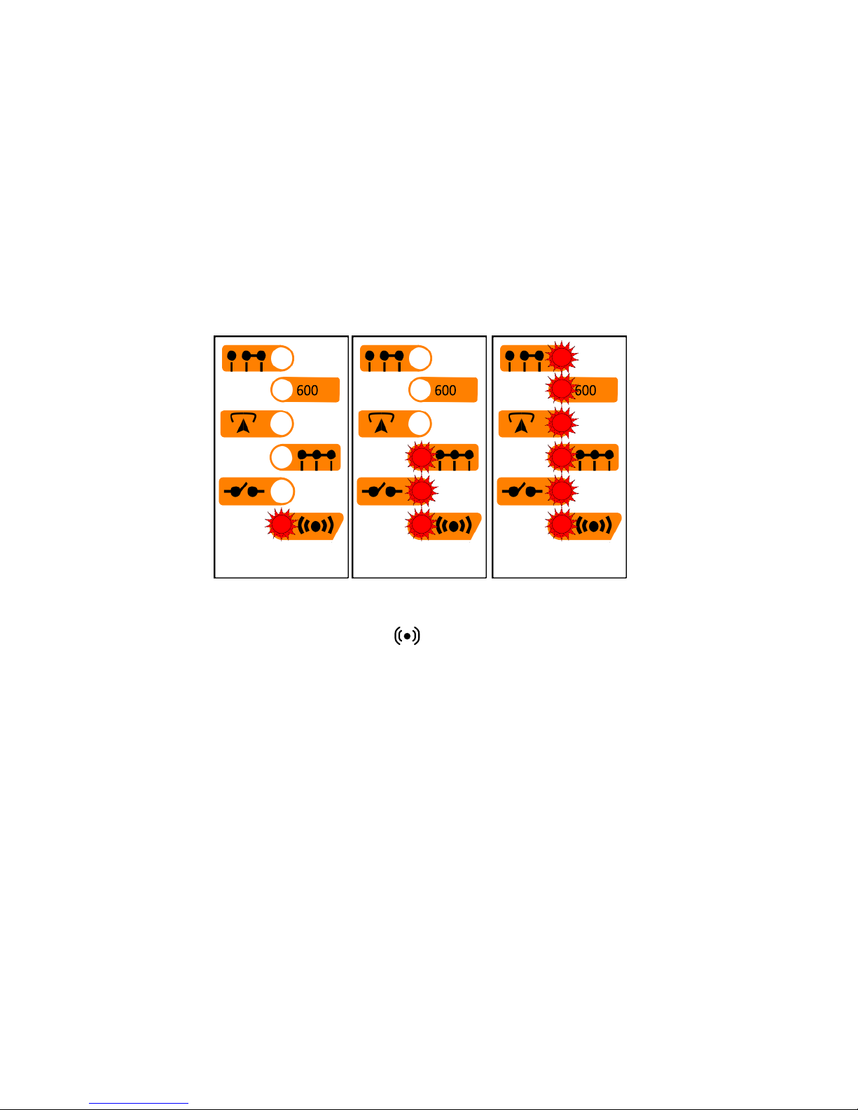
The OSCILLATOR flashes all six of its lights (LEDS) once
simultaneously (< 0.5sec) to indicate that the leads have been
correctly inserted and battery power is present. The OSCILLATOR
then performs a battery level check and displays the battery strength
in the form of a light array bar graph. Maximum battery capacity
displays all six lights but if the battery is nearly flat and needs
replacing, only one light is displayed (See figures 4-1a, 4-1b, 4-1c).
If no lights are displayed then the battery voltage is insufficient for
any operation and should be replaced.
Figure 4-1 Light array indicating: (a) FLAT, (b) LOW, (c) FULL battery level
After indicating the battery level the OSCILLATOR enters TONE
mode. The light next to the symbol will flash every 3 seconds
indicating that the OSCILLATOR is on and generating a tone
signal.
The factory default tone is referred to as the Warble. This is the
tone that will be heard coming from the PROBE when using the
OSCILLATOR in TONE mode for the first time. Three other tones
are available and can be selected using the PROBE (refer to section
5.3 TONES).
4.2. OSCILLATOR POWER OFF
Removing the OSCILLATOR’s test lead from the socket
immediately turns off the OSCILLATOR.
4.3. CABLE SHORT CIRCUIT DETECTION
When this feature is enabled, the OSCILLATOR can be used for
confirming traces over short distances without using a PROBE.
(b) LOW BATTERY
(c) FULL BATTERY
light
on
(a) FLAT BATTERY
Page 9
pg. 9
To enable this feature, connect the PROBE leads to the
OSCILLATOR Blue test leads, either directly or via an unbroken
cable pair. Press the PROBE’s and 600 keys simultaneously
and hold them down for about 1 second until a beep is heard. This
places the OSCILLATOR into TONE mode (the warble tone will be
produced) and causes the OSCILLATOR to sound its buzzer if
either a short circuit or a reverse polarity battery is present between
its Blue test leads. The enabled / disabled status is non-volatile and
will not change, even if the battery is removed. If enabled, the
oscillator will beep three times when it is turned on.
To disable this feature, perform a factory reset, i.e. connect the
PROBE leads to the OSCILLATOR Blue test leads, and press the
PROBE’s and keys simultaneously and hold them down
for about 1 second until a beep is heard.
Note: When in TONE mode, the OSCILLATOR applies a nominal 4.5
V DC to the cable pair to which it is connected. This voltage is
necessary for the OSCILLATOR to be able to detect a short circuit.
4.4. OSCILLATOR MODES
The OSCILLATOR has six operating modes. The selected
operating mode is indicated by a flashing light on the
OSCILLATOR next to the mode symbol. The modes are:
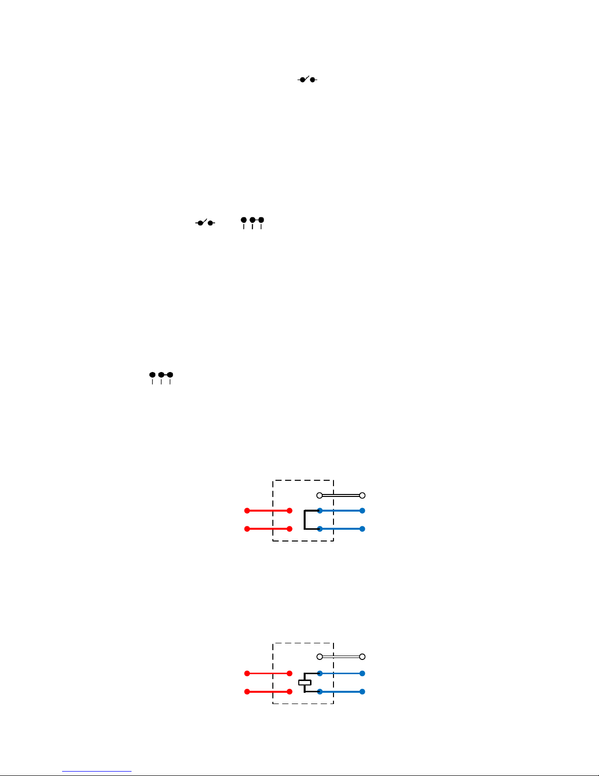
Short Circuit (Without White Wire)
The OSCILLATOR tone generation is stopped and the cable line is
looped. The White lead and the Red leads are open circuit. After
disconnecting the PROBE leads from the line, the loop resistance
and ground leakage can be measured. An RFL Bridge can be used
to locate any short circuit faults on the line (See section 6.3.1, Two
Wire Test). A TDR can measure the distance to the OSCILLATOR.
CustomerExchange
600 Quiet Line – 600 Ω termination
The OSCILLATOR tone generation is disconnected and the line is
terminated with an AC coupled 600 Ω. This termination is suitable
for measuring line noise or Return Loss. The White lead and the
Red leads are open circuit. The termination is 900 Ω in regions
where this is the standard network termination.
CustomerExchange
Page 10
pg. 10
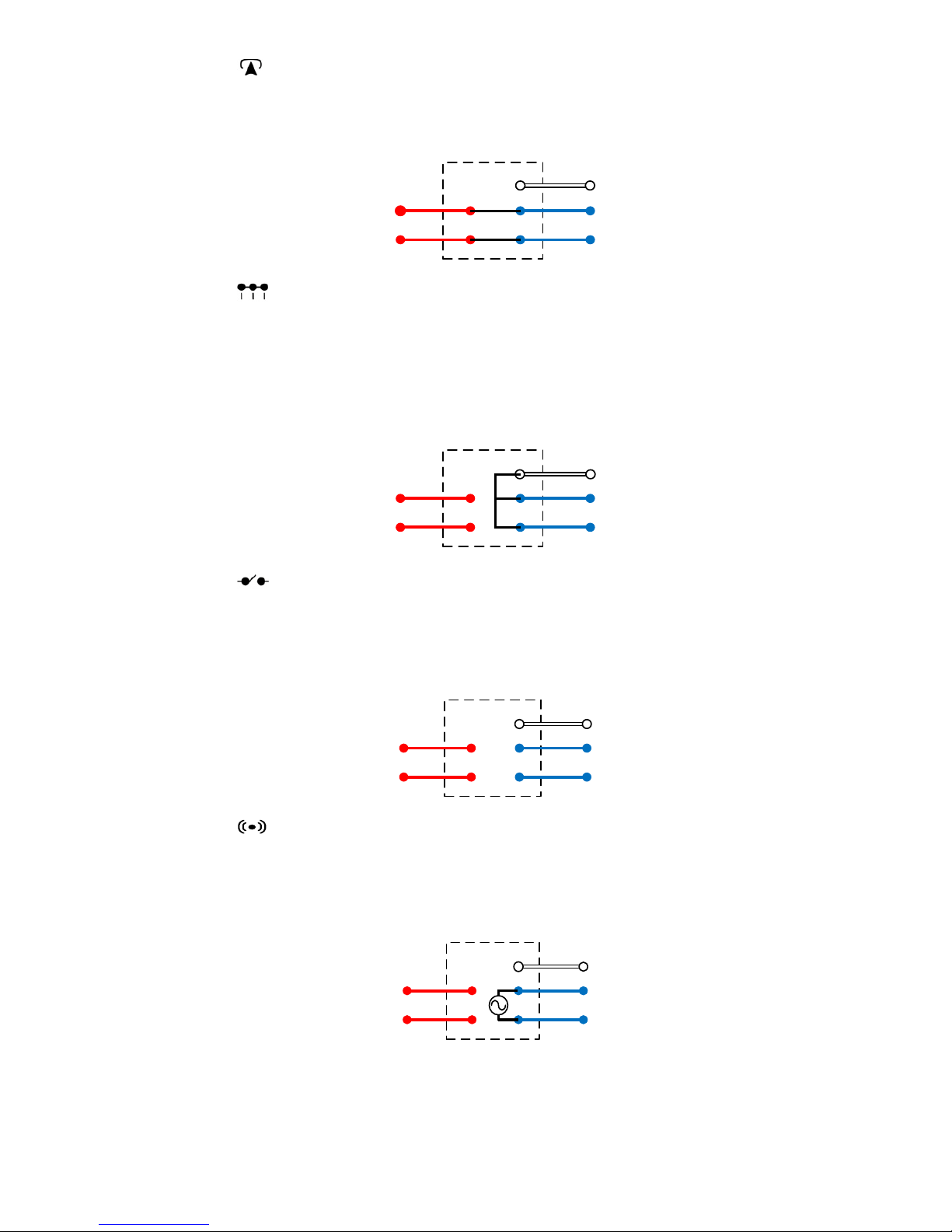
Exchange Connect
The OSCILLATOR tone generation is disconnected and the line is
connected through to Exchange using the Red leads. The White lead is
open circuit.
CustomerExchange
Short Circuit (With White Wire)
The OSCILLATOR tone generation is disconnected and the line is
looped. The White lead is shorted to the Blue leads and the Red leads
are open circuit. After disconnecting the PROBE leads from the line,
the loop resistance and ground continuity may be measured. This
termination is also used for a Three Wire RFL test, (refer to section
6.3.2 Three Wire Test).
CustomerExchange
Open Circuit
The OSCILLATOR tone generation is disconnected and the line is
isolated from the Exchange. After disconnecting the PROBE leads
from the line, insulation resistance, foreign battery voltage or TDR
open circuit tests can be performed.
CustomerExchange
Tone Mode (Pair Identify)
The OSCILLATOR is disconnected from the Exchange and a tone
signal is output on the Blue test leads. The White lead is open circuit.
The PROBE tip is used to detect the tone signal at the Far End (refer to
section 6.1 PAIR IDENTIFICATION).
CustomerExchange
Page 11

pg. 11
5. PROBE OPERATION
5.1. SIGNAL TRACING
To trace the tone signal generated by the OSCILLATOR, slowly
move the PROBE’s antenna within close proximity to the cables
under test. A tone signal picked up on the PROBE antenna will be
reproduced as an audible tone. The audible tone volume increases
as the PROBE antenna tip is brought closer to the cable carrying the
tone signal. This tracing technique is used in Pair Identification
(refer to section 6.1 PAIR IDENTIFICATION.).
5.2. MODE SELECTION
Each key on the PROBE selects one of the six OSCILLATOR
modes. The symbols on the PROBE keys are identical to the
symbols displayed on the OSCILLATOR, (refer to section 4.4
OSCILLATOR MODES).
The PROBE must be connected to the same unbroken line as the
OSCILLATOR to control the OSCILLATOR. Holding a single key
down for about 1 second will cause the PROBE to transmit a
command to the OSCILLATOR to change operating mode. The
PROBE will then beep once and power down, except in the case of
TONE mode, where it will remain powered for 2 minutes and then
power down automatically.
5.3. TONES
There are four selectable OSCILLATOR tones available for use in
pair identification, they are:
• Warble;
• Continuous
• Two high beeps repeating; and
• Three high beeps repeating.
The factory default tone generated by the OSCILLATOR is the
Warble, and this is the tone heard when using the OSCILLATOR
for the first time in TONE mode.
To select a different tone, first connect the PROBE to the same line
as the OSCILLATOR. The technician must then hold the PROBE’s
TONE key down for about 1 second until a SINGLE beep is
heard. If the key continues to be held down for a further second
after the first beep is heard, the PROBE will generate a double beep
indicating that the PROBE has changed from low to high sensitivity
(soft to loud). The PROBE will continue to cycle between high and
low sensitivity until the TONE key is released.
The selected tone is saved when the OSCILLATOR is powered off.
For example, if the tone is on ‘Warble’ and the technician changes
the tone to ‘Two high beeps repeating’, the OSCILLATOR will then
start up next time with the ‘Two high beeps repeating’.
Page 12
pg. 12
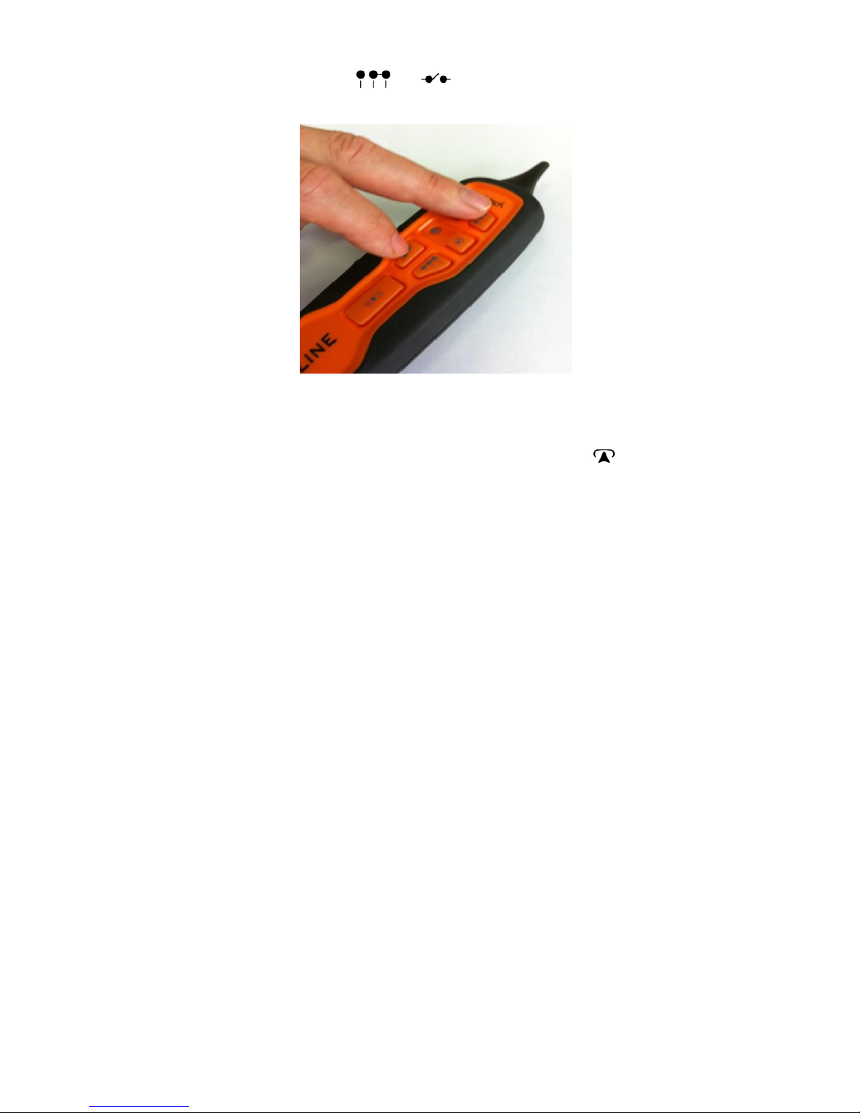
The factory default tone can be restored by simultaneously pressing
and holding down the and keys on the PROBE for 1
second until a beep is heard, see Figure 5-1.
Figure 5-1. Reset Tone to Warble (Factory Default)
5.4. CONNECTED TO EXCHANGE
The PROBE has a red/green light located to the left of the key.
This will light up when the PROBE is connected to a cable pair that
has a battery connected to it that is > 15 V DC. The light colour
displayed indicates the polarity of the line: Green light indicates a
negative Exchange battery on the test lead’s Black clip. Red light
indicates a negative Exchange voltage on the test lead’s Red clip.
5.5. AUDIO BATTERY LEVEL INDICATOR
If the PROBE battery is almost flat, the PROBE will emit a long and
descending pitch screech whenever a key is pressed. This is easily
distinguishable from the normal higher pitch beep emitted when a
key is pressed when operating from a sufficiently charged battery.
The battery should be replaced to ensure correct operation.
6. LINE TESTS
6.1. PAIR IDENTIFICATION
Power on the OSCILLATOR by inserting the test lead into the 6-pin
socket.
For Pair Identification it is sufficient to connect the
OSCILLATOR’s blue leads to the line as follows:
Blue test lead with Red clip to Pair ‘a’ wire
Blue test lead with Black clip to Pair 'b' wire
Note: Reverse the clips if the OSCILLATOR beeps, indicating
incorrect polarity.
Page 13

pg. 13
However, should the technician wish to perform additional tests
following the Pair Identification process, it is recommended that the
following connections be made prior to commencing Pair
Identification:
Red test lead with:
Red clip to Exchange 'a' wire (+’ve);
Black clip to Exchange 'b' wire (-‘ve);
Blue test lead with:
o Red clip to Exchange 'a' wire (+’ve);
o Black clip to Customer 'b' wire (-‘ve);
Connect White lead to the cable sheath (‘e’);
Remove jumper.
Note: If the leads are not connected this way then it is possible to
short a customer's working service if the cross-connection (links,
jumper, etc.) have not been opened and the OSCILLATOR is
switched to EXCHANGE CONNECT mode. Similarly, a short
circuit can occur when the cross-connection is being restored and
the Oscillator has been left in EXCHANGE CONNECT mode.
Move to the Far End of the Line and use the PROBE tip to identify
the cable pair carrying the OSCILLATOR tone signal. Confirm the
pair by selecting a different mode and checking that the
OSCILLATOR’s tone stops. The PROBE’s sensitivity (volume)
can be adjusted by using the TONE key (refer to section 5.3
TONES).
6.2. CHECK FOR BALANCED PAIR
This is accomplished by moving the PROBE tip between the ‘a’ and
‘b’ wires of the cable pair carrying the signal and identifying a null
point (place of negligible signal volume). If no null point is found
then the cable pair is unbalanced and a cable fault is likely present
(refer to section 6.3 FAULT LOCATION).
6.3. FAULT LOCATION
A technician should refer to their fault location test instrument’s
manual for more details. In these manuals the Oscillator is often
referred to as a Remote or Far End Device (FED).
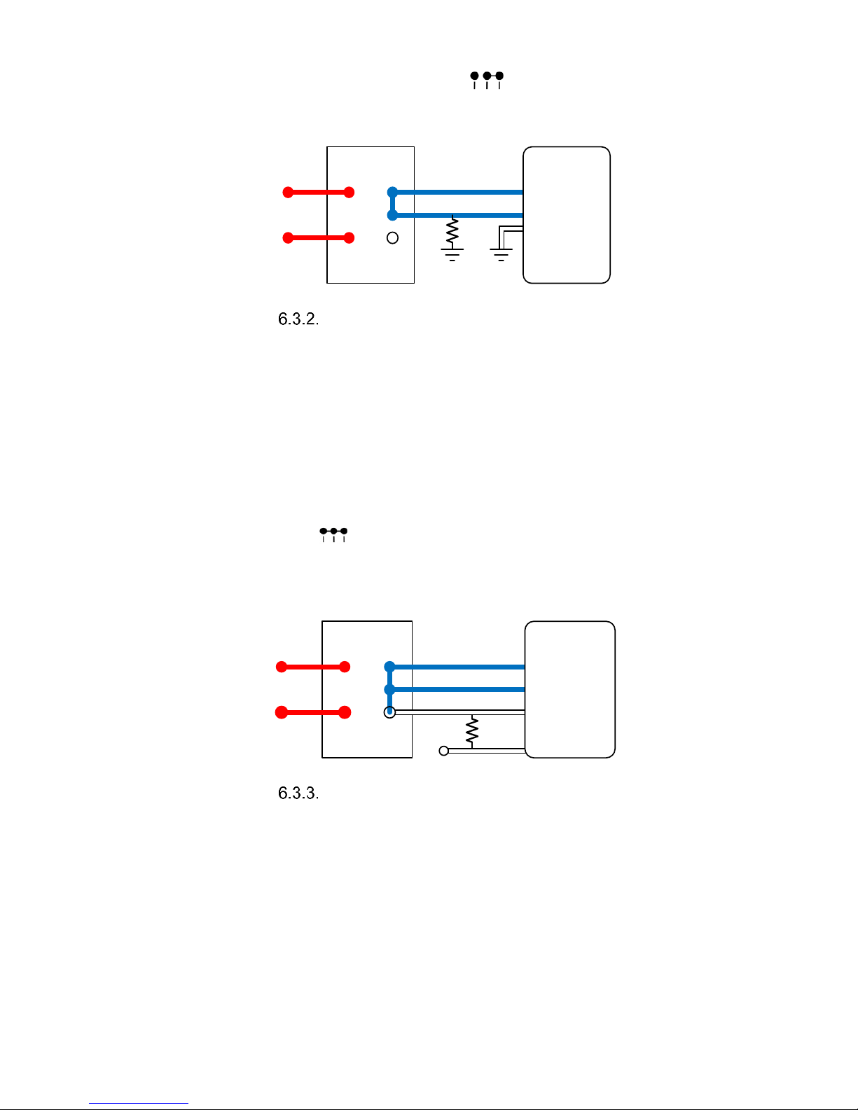
Two Wire Test
This test is performed on a pair containing one good wire and one
faulty wire with leakage to ground. The test requires the use of a
Resistance Bridge in addition to the Loop-a-Line. The test is as
follows:
At the Exchange, connect the Blue and Red
OSCILLATOR leads (refer section 6.1 PAIR
IDENTIFICATION);
Page 14
pg. 14
At the customer end, identify the line pair and connect the
PROBE test leads, then press key;
Disconnect the PROBE and connect the Resistance Bridge
and locate the fault (as per the instrument’s manual).
Oscillator
Resistance
Bridge
Fault
Locator
Three Wire Test
The Three Wire Method for resistance fault location is used when
there is a “good” pair available in the cable and the other two wires
of the “faulty” pair have fault resistance between them, or both have
fault resistance to ground. If only one wire of the pair is faulty, the
Two Wire Method can be used. The Three Wire test is performed as
follows:
Connect the Blue Oscillator leads to a good pair and the
White Oscillator lead to one wire of the faulty pair;
Connect the PROBE’s blue leads to the good pair at the
Far End;
Press SHORT (WITH GROUND) to connect the
Blue leads and the White lead together;
Disconnect the PROBE and carry out fault location using
a Resistance Bridge.
Oscillator
Resistance
Bridge
Fault
Locator
Pulse Echo Test (PET/TDR)
The SHORT / OPEN mode can be used to calibrate a PET (TDR)
for length of line to Oscillator.
Page 15

pg. 15
7. SPECIFICATIONS
7.1. OSCILLATOR
Battery 9 V, alkaline IEC 6LR61
LED low battery indication
Short circuit detection, battery reverse polarity on Blue test leads
Weight and dimensions: 110 g 240 mm x 35 mm x 25 mm
Mode 1: Tone (Pair I/D)
Tone output 1 kHz-2 kHz
Selectable warble(default), continuous, two tone beeps repeating and
three tone beeps repeating
Enable/disable buzzer for short circuit & battery reverse polarity
detection
Max consumption, line pair short circuited and buzzer enabled = 8.8 mA
(70.5 hours, 580 mAh battery)
Tone output level into Line +9 dBm into 600 Ω
Output impedance 600 Ω
Mode 2: Open Circuit
Current consumption approx. 0.75 mA
Resistance between terminals > 1GΩ
Max open circuit voltage 500 V dc
Line Balance: 54 pF (black clip-red clip), 58 pF (black clip-ground
plane), 72 pF (red clip-ground plane)
Mode 3, Mode4: Short Circuit (with or without ground)
Current consumption approx. 0.75 mA
Max short circuit current 2 A
Resistance between terminals, < 0.30 Ω
Mode 5: Connect Exchange
Current consumption approx. 0.75 mA
Mode 6: 600 Ω termination
600 Ω or 900 Ω cable pair termination, configuration for noise
measurement
Current consumption approx. 0.75 mA
7.2. PROBE
Battery 9 V, alkaline IEC 6LR61
Low battery indication using low frequency beep
Tone receiver, loudspeaker or earphone output (<2000 Ω )
High and low tone sensitivity settings
Tone receiver mode automatically powers off after 2 minutes
Max current consumption in tone receiving mode approx. 98 mA
Current consumption in other modes <1 uA
Green/Red LED shows exchange connected
Weight and dimensions: 130 g 200 mm x 50 mm x 28 mm
Page 16

pg. 16
8. WARRANTY
Teletech Pty Ltd provides 12 month warranty for the TX916.
The warranties do not cover any product that has been
misused, abused, improperly or poorly used or disassembled.
The warranty covers any product that becomes defective under
reasonable normal usage as determined solely by Teletech Pty
Ltd.
Items returned for repair or replacement shall be shipped with
a copy of the dated invoice, freight charges prepaid to:
Teletech Pty Ltd
Unit 8
2-6 Apollo Court,
Blackburn 3130 VICTORIA
AUSTRALIA
Tel:
+61
3 9877 3033
Fax:
+61
3 9878 6322
For sales and support
Email…. [email protected]
www.teletech.com.au
MADE IN AUSTRALIA
Copyright Teletech Pty. Ltd. 2017 ©
Document Version 2.5
Quality
ISO 9001
 Loading...