

TELETECH TX905 Instructions Manual
TX905 CABLEMATE
Blue
White
Red
CUST
EXCH
Red
Blue
White
Red
CUST
EXCH
Red
Blue
White
Red
CUST
EXCH
Red
Blue
White
Red
CUST
EXCH
Red
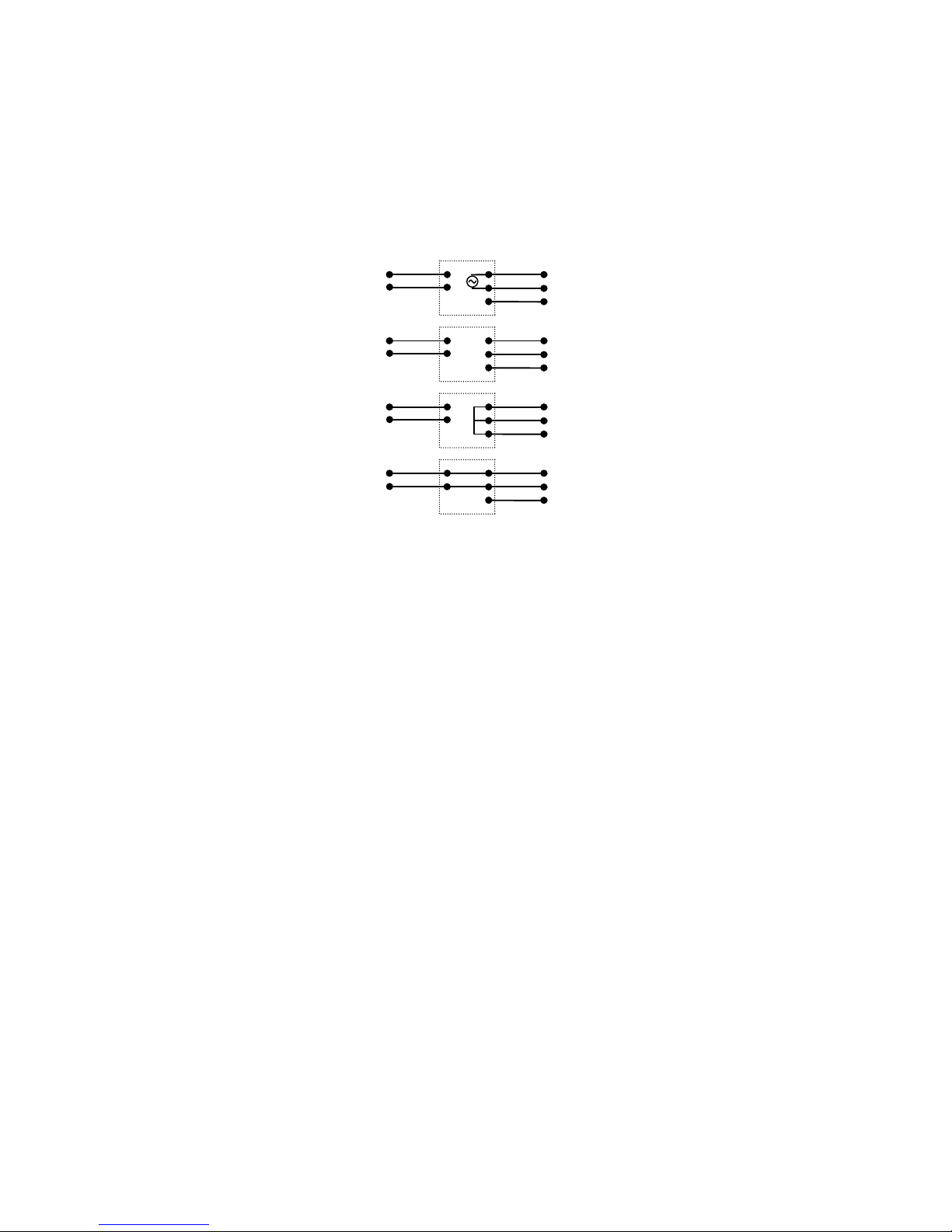
PAIR IDENTIFY
OPEN CIRCUIT
LINE LOOPED
EXCHANGE
Cablemate comprises two components:
(a) Probe – used for tone search, cable pair identification and
to control the mode of the Oscillator unit.
(b) Oscillator – provides ‘pair identify’ signal to line. Also, on
receiving signals sent from the probe, the oscillator will
switch directly to the mode selected, Pair Identify, Open
Circuit, Short Circuit or Exchange Connect. The Red
LED indicates power is on and the battery is OK. At
switch-on the LED should light continuously for 2 seconds,
then flash once per second indicating that it is ON. If the
LED flashes rapidl y at switch-on then the battery needs
replacing.
CONNECT
Note: Switch on always selects Pair Identify Mode.
PAIR IDENTIFICATION
(1) Connect the Blue and Red Oscillator leads to the line (Red
to Exchange and Blue to Customer – W hite Not Used). Switch
on by pressing the POWER button. Select the type of tone by
pressing the TONE button. The tone can be monitored using
the Probe.
(2) Move to far end of line and use Probe tip to identify cable
pair carrying the Oscillator Signal. The Probe sensitivity can be
selected by pressing the TONE button. The pair can be verified
by checking for a null (minimum signal) between the wires
carrying the tone. No null will be found if the pair is
unbalanced.

LINE TESTING
(1) Identify the pair at the customer end.
(2) Insert Probe leads and connect to the identified pair. Press
a Probe button to change the Oscillator to the selected mode.
(3) Open Circuit. Oscillator tone is disconnected and line is left
open circuit. After disconnecting Probe leads from line,
insulation resistance tests may be done on the open line.
(4) Short Circuit. Oscillator tone is disconnected and line is
looped. White wire is also shorted to line. After disconnecting
Probe leads from line, loop resistance may be measured.
(5) Exchange Connect. Oscillator tone is disconnected and
line is connected through to exchange. Green LED on Probe
indicates that 48Vdc is connected to line.
FAULT LOCATION
Two Wire Test
Used with a single pair containing one good wire and the faulty
wire.
(1) Disconnect the pair under test from the exchange.
(2) Connect the Blue Oscillator leads to the pair under test
(white lead not used).
(3) At the customer end identify the pair and press OPEN to
disconnect the oscillator from line.
(4) Disconnect Probe Leads and test the line to identify the
faulty wire.
(5) Press SHORT to loop line then carry out fault location.
Three Wire Test
(1) As for Two-Wire Test but connect the Blue leads to a good
pair and the White lead to the faulty wire. Note that in Short
Circuit Mode, all three wires are looped at the Oscillator.
Pulse Echo Test (PET)
The loop / unloop facility can be used to calibrate a PET for
length of line to Oscillator.
Teletech Pty Ltd
61 Betula Ave,
P O Box 85, Vermont, VIC 3133
Tel: 03 9873 2777
Fax: 03 9873 5902
 Loading...