

Page 1

1
TX 150
CABLE MAPPING
Operator’s Manual
Software Version 1.5.0
Page 2
2
1 PHYSICAL DESCRIPTION
A TX150 kits consist of the following minimum items:
2 x TC150 controller;
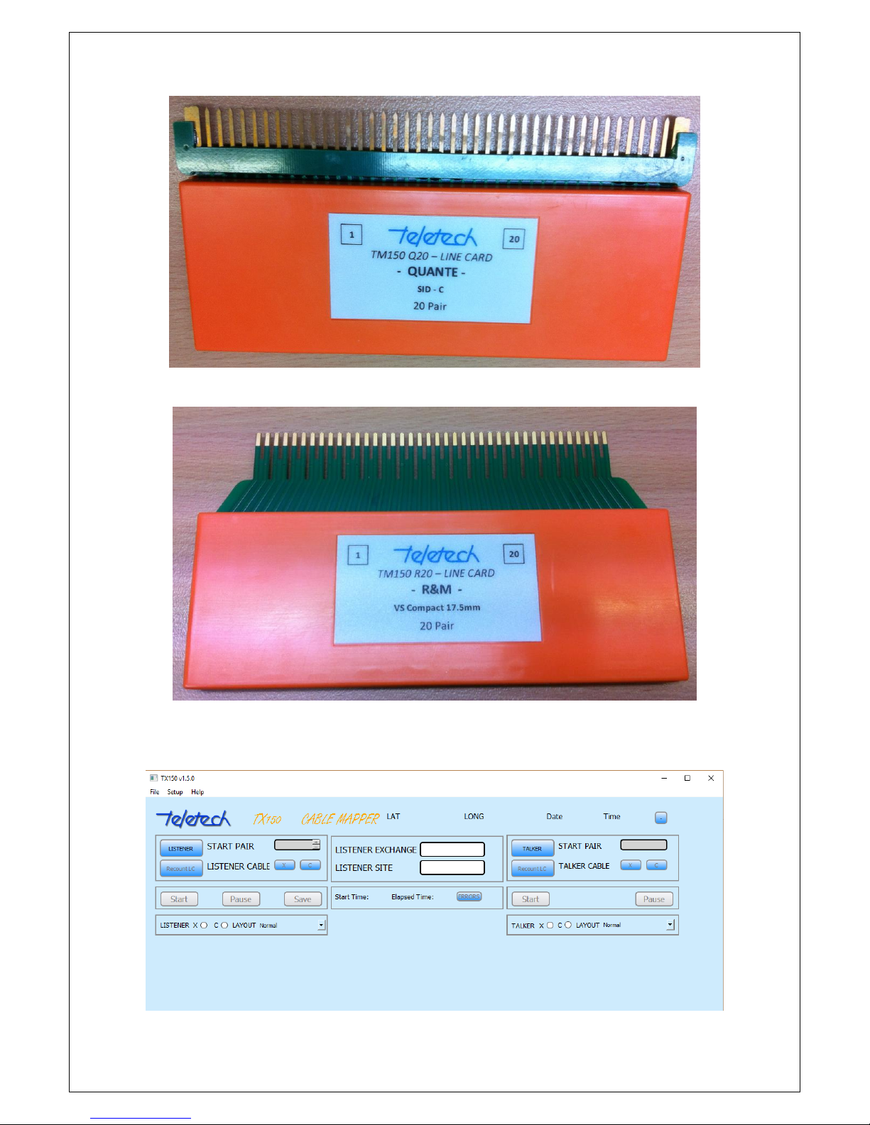
2 x Line Cards;
A Windows Application; and
Associated cables and leads
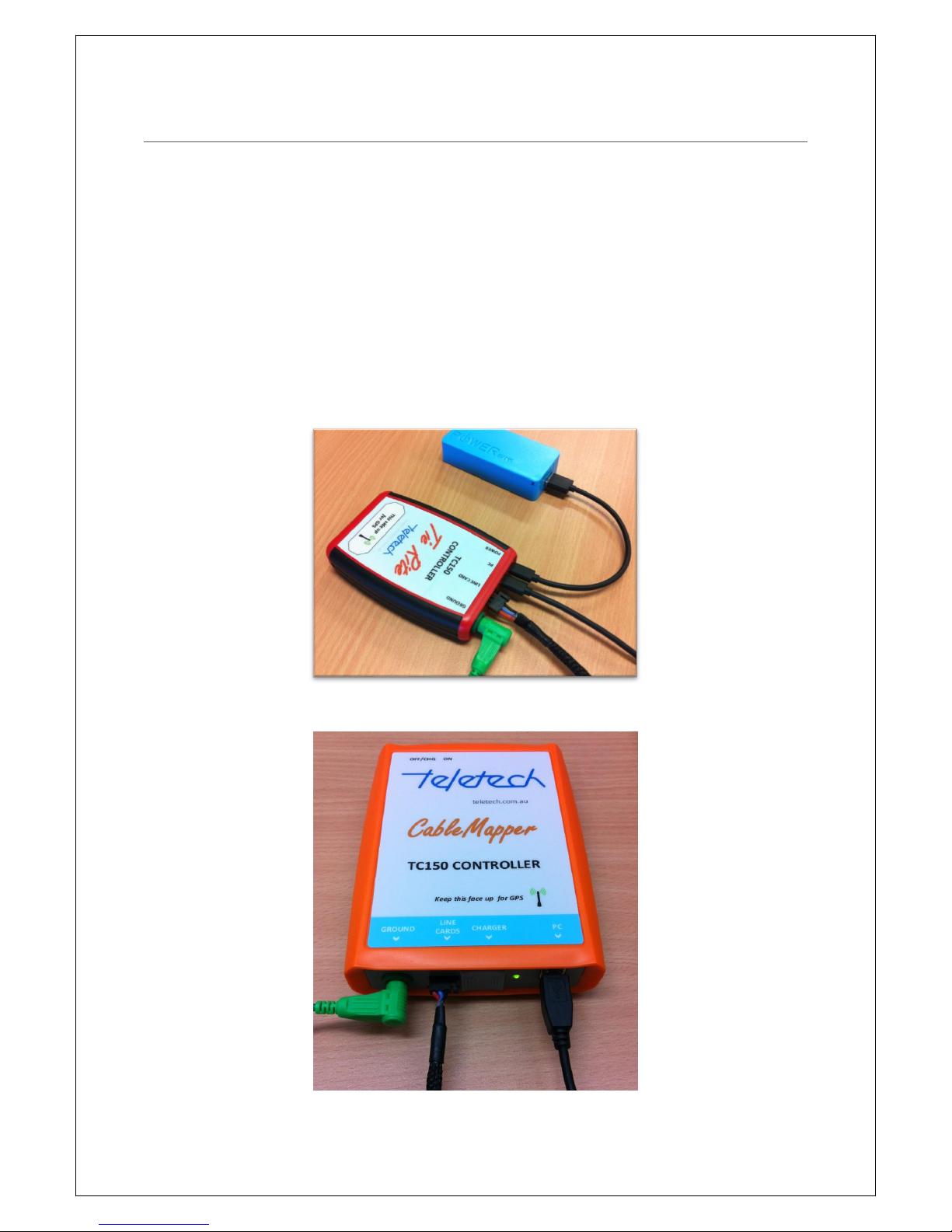
TC150 Controllers. There are two models of the TC150 controller, they are:
Tie Rite (with an external battery); and
TC150 Cable Mapper Controller (with an internal battery and On/Off switch).
TC150 Tie Rite Controller
TC150 Cable Mapper Controller
Page 3
3
Quante 20 pair Line Card
1R&M 20 pair Line Card
TX150 Windows Application version 1.5.0
Page 4

4
2 TABLE OF CONTENTS
1 Physical Description ........................................................................................................................ 2
3 Safety Information .......................................................................................................................... 5
3.1 Warnings and Precautions ...................................................................................................... 5
4 Changes from Previous Version ...................................................................................................... 6
5 Basic Set Up ..................................................................................................................................... 6
6 Connecting the Talker ..................................................................................................................... 7
7 Set Up the Talker ............................................................................................................................. 8
8 Connecting the Listener ................................................................................................................ 10
9 Set Up the Listener ........................................................................................................................ 10
10 Testing Options ......................................................................................................................... 13
11 TX150 Windows Application ..................................................................................................... 14
11.1 Layout and Pop-ups .............................................................................................................. 14
11.2 Menu Bar - File, Setup and Help ........................................................................................... 17
11.3 Results Colour Scheme .......................................................................................................... 18
11.4 App Titles & Button Meanings .............................................................................................. 20
11.5 Saving your work (csv) .......................................................................................................... 22
12 Termination Errors .................................................................................................................... 23
13 Tips ............................................................................................................................................ 24
14 Technical Information ............................................................................................................... 25
15 Warranty ................................................................................................................................... 26
Page 5
5
3 SAFETY INFORMATION
To avoid injury read “Safety Information” and “Warnings
and Precautions” before using this instrument
Safe Working Practices
Review the safety information and adhere to the safe working practices
described in this manual and elsewhere.
Protection may be impaired if the instruments are used for purposes other than described in this
manual.
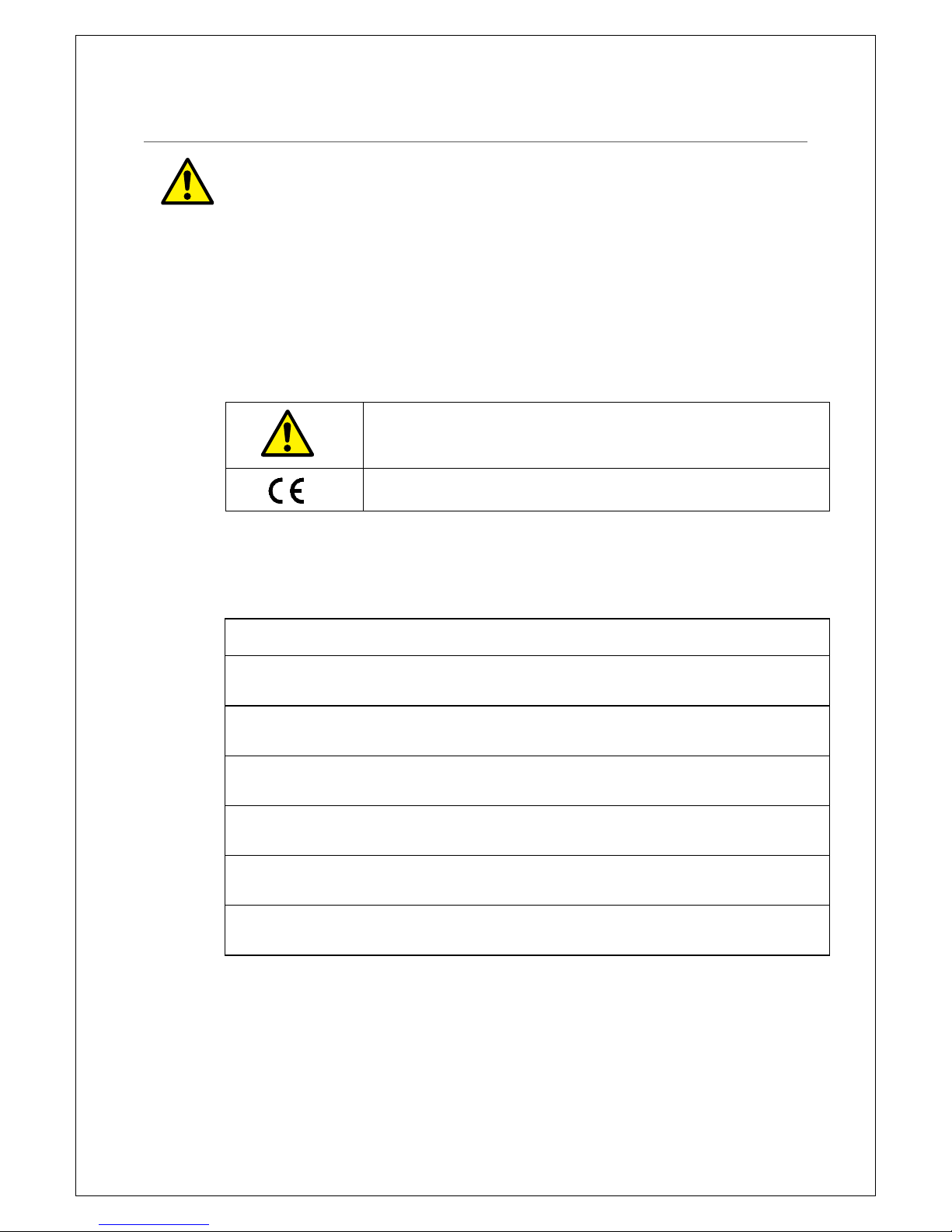
The symbols used on the instrument and in this manual are:
Safety Information Warning,
Refer to Manual
Conforms to European Union Directives
3.1 WARNINGS AND PRECAUTIONS
To avoid possible electric shock or personal injury, and to avoid possible damage to the instrument
or to the equipment under test, adhere to the following practices:
This equipment is to be used by trained operators only.
Before using the equipment inspect the case. Do not use the equipment if it is damaged. Look
for cracks in the case or missing parts.
Inspect the test leads for damaged insulation or exposed metal. Check the test leads for
continuity. Replace damaged test leads before using the equipment.
Do not use the equipment if it operates abnormally. Protection may be impaired. When in doubt
have the equipment serviced.
This equipment must not be connected to active telecommunications circuits. Do not apply any
network voltages to the equipment.
When connecting the test clips be sure to keep your fingers away from potentially live metal
parts.
Do not use this device during electrical storms.
Page 6
6
4 CHANGES FROM PREVIOUS VERSION
The major changes from version 1.4.0 are:
Auto-save function introduced;
User control over: font sizes, default grid layout and Auto-save time delay;
Increased Grid area after the Input section is collapsed;
Controllers are registered as being either a Talker or a Listener – when they are plugged in
the appropriate area is highlighted ;and
The ability to load in a previous job from a saved csv and continue mapping. Note this only
applies to version 1.5 saved csv file.
5 BASIC SET UP
The TX150 is designed to check cable terminations between each end of a multi-pair cable. Line
Cards are plugged into the terminating blocks at each end. At each end the Line Cards are joined
together with Link Cables and the first Line Card at each end is connected to a Controller (TC150).
The Controller and Line Cards at each end are powered by a separate battery. Each Controllers can
operate up to 600 pairs at the same time and the batteries will last more than 20 hours of normal
use from full charge.
One end is designated the Talker and the other end is designated the Listener. The Talker end sends
signals on each pair of the cable and the Listener end identifies these signals. All signals are
transmitted simultaneously so identification of pairs is very quick (less than 10 seconds).
The Listener and Talker are set up by a Windows laptop. The laptop is connected to the controller
by a USB cable. The Operator will launch the TX150 Windows Application from the icon on the
laptop (see later section).
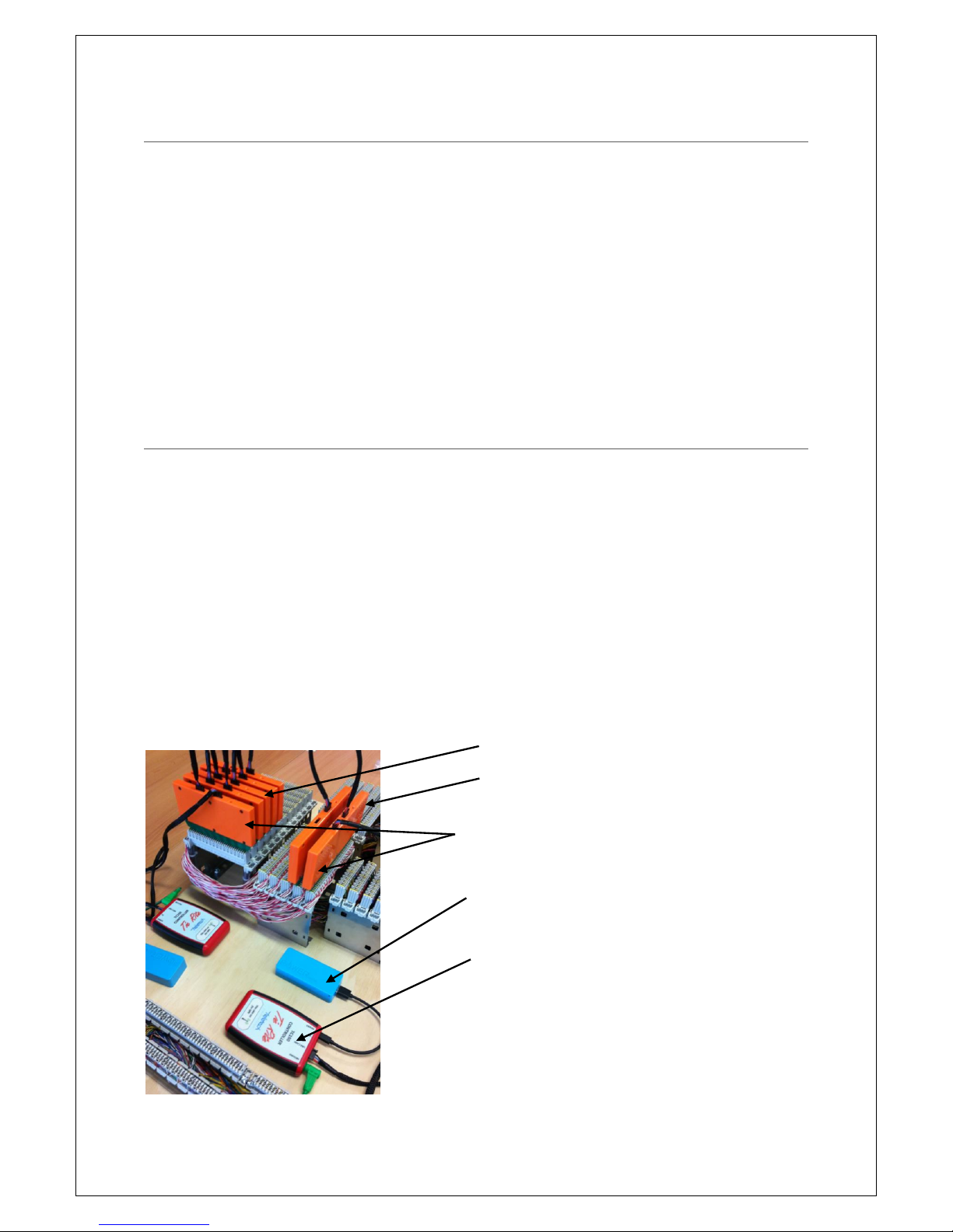
Fig 2 Talker & Listener setup on a Test Jig (not connected to a laptop)
Talker Side
Listener Side
Line Cards
Battery
TC150 Controllers
Page 7
7
6 CONNECTING THE TALKER
Connect the Line Cards to the terminal blocks at the Talker end. (If you are testing using 16-way
R&M connectors this end must be the Talker). Be mindful of the following:
Start from the lowest numbered pairs;
Observe the pair 1 indicator on the Line Card label; and
Be sure to orient the Line Cards the correct way up.
Connect the following components of the TX150 kits:
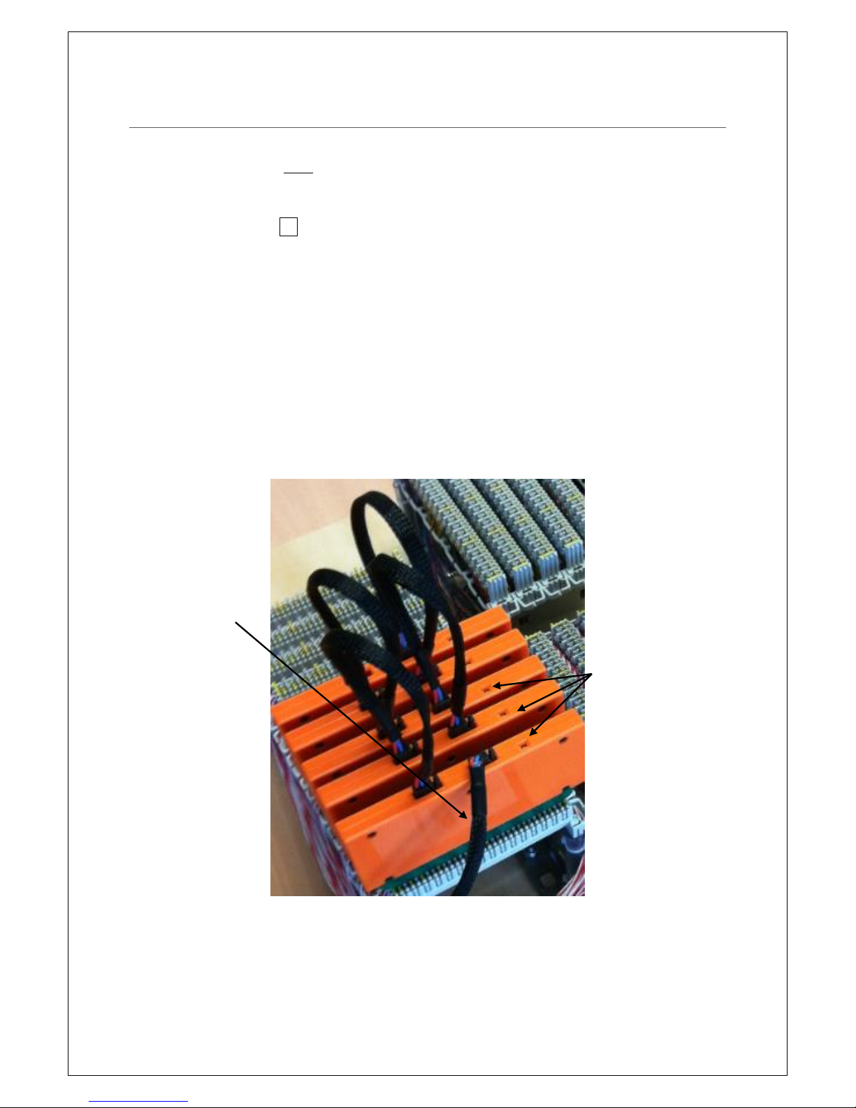
Link Cables to each Line Card in a daisy chain arrangement. The first Line Card (lowest pair
number) connects to the second line card and the second connects to the third etc.;
Ground lead (green lead) from the TC150 to the frame ground;
First Line Card to the Controller (TC150) using the long Link Cable (1.5m);
Battery to the Power input on the Controller – to the connector labelled “Power”; and
Your laptop to the Controller by a USB cable – to the connector labelled “PC”.
Fig 3 Line Cards Daisy Chained Together
Link cable connecting
the Line Cards to the
TC150 Controller
Line Card LED indicator
Page 8
8
7 SET UP THE TALKER
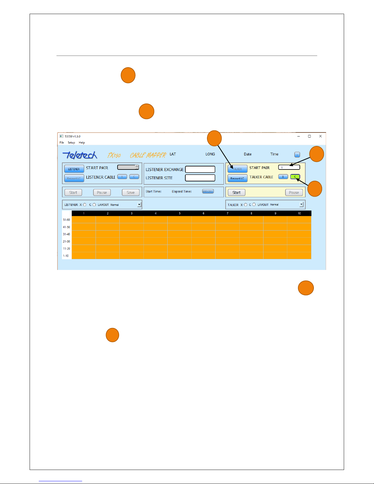
Open the TX150 Application.
Click the TALKER button . The program will respond with a message saying it is locating the
position with the GPS. If you are inside a building or under cover or using a separate PC at the talker
and listener ends cancel this, otherwise wait a maximum of a minute and a half (100 seconds) for the
GPS to locate your position.
Insert the starting pair number . If you are testing from the 16-pair R&M connectors enter the
Row number of the first connector instead of the pair number.
Fig 4 TX150 App screen - with 6 x 10 pair Line Cards
Tab to or click the type of cable to be tested (C or X) – for Customer (C) or Exchange (E) cables .
The exception is for R&M 16s, where the X and C are communicating simultaneously to the Listener.
Click the Tab or Enter on the keyboard after entering the Start Row. The program will respond by
indicating in an Orange colour the number of Line Cards and Pair numbers (or rows) connected by
the Line Cards. This is indicated in a Grid.
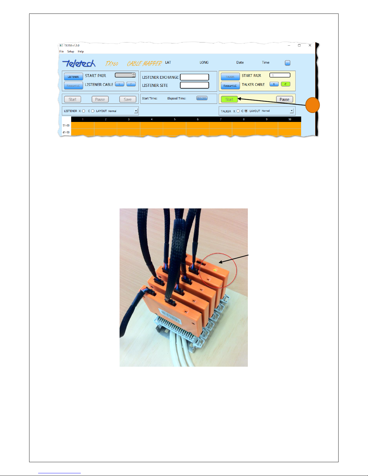
Finally click START . A notification that the line cards are talking will appear for 2 seconds. The
Start button will highlight in green to provide feedback to the user.
Grid of Orange. The controller has identified 6 x 10
pair Lind Cards are connected.
1
1
2
2
3
3
Page 9
9
Fig 5 TX150 App screen – Line Cards are now Talking
Note: The Line Cards will continue ‘talking’ until:
the battery is disconnected or runs flat;
they are disconnected from the TC150 controller; or
they are reconnected to the Laptop and the program closed.
Disconnect the laptop from the TC150 Controller. Take the laptop to the other end of the telephone
cable where it terminates at either a Pillar or a Node. Note that the Talker Line Cards will continue
to ‘talk’ until either they are disconnected from the TC150 controller or the Talker battery runs flat.
The LED indicator on the last (highest
pair number) line card in the chain will
light green
4
Page 10
10
8 CONNECTING THE LISTENER
Connect the Line Cards to the terminal blocks at the Listener end that the Talker is connected to.
Again observe pair 1 indicator on the Line Card label to determine the correct Line Card
orientation.
Connect the following components of the TX150 kits, they are:
Short Link Cables to each Line Card in a daisy chain arrangement. The first Line Card (lowest
pair number) connects to the second line card and the second connects to the third etc;
Ground lead (make sure the lead is clipped to an earth point on the cabinet/pillar);
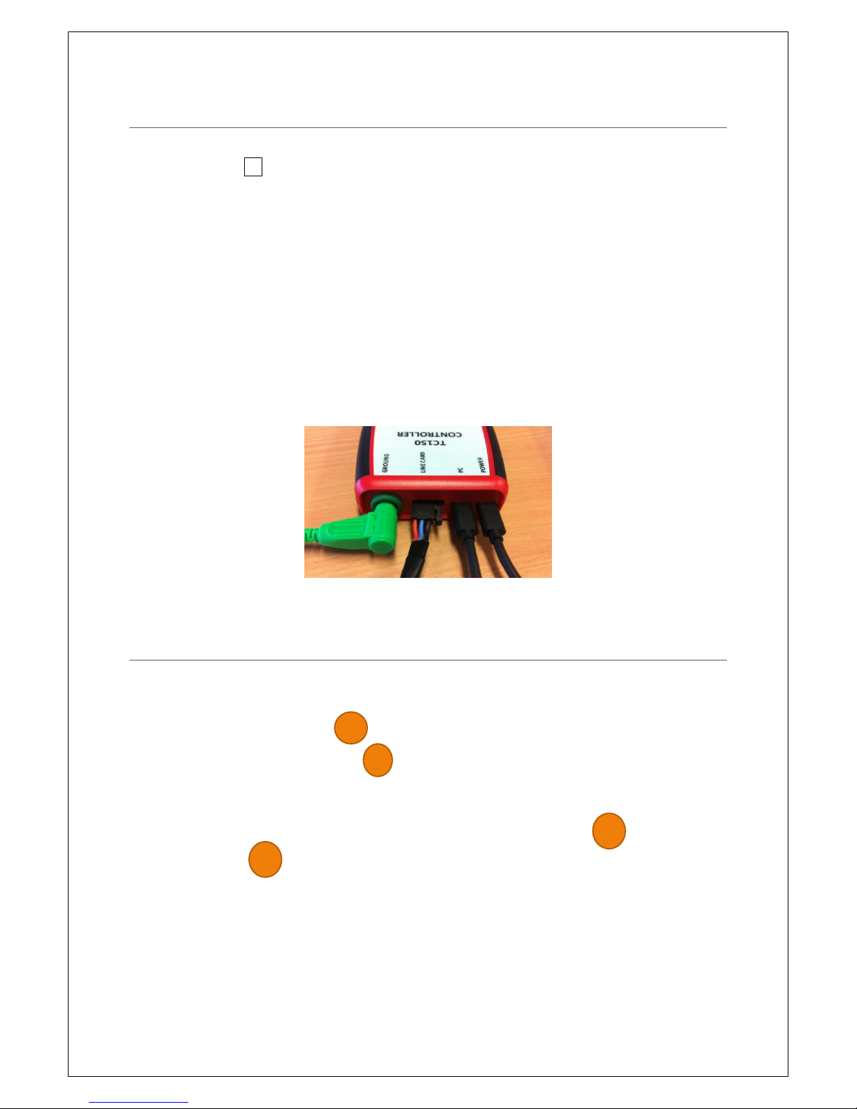
First Line Card to the Controller (TC150) using the long Link Cable; and
The Battery to the Power input on the Controller.
Connect your laptop to the Controller by a USB cable (be sure to disconnect from the talker
controller first).
Fig 6 TC150 Tie Rite Controller connected to Ground, Line Card, PC/Laptop and Power (a battery)
9 SET UP THE LISTENER
If you are using the same laptop at each end, the TX150 Application will still be open, otherwise
open the TX150 Application. Perform the following steps:
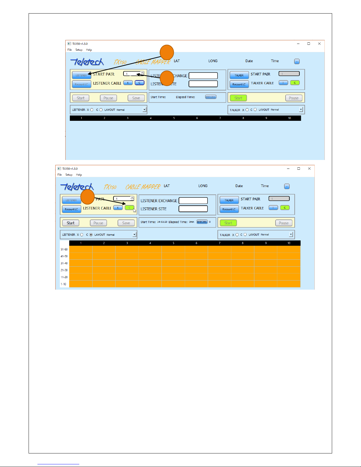
Click the LISTENER button ;
Insert the starting pair number ;
Click the type of cable to be tested (C or X). If a tab key is used the X or C button will be
given a black background highlight. The program will respond by indicating in an Orange
colour the number of Line Cards and pairs connected to the controller ; and
Click START .
3
4
Page 11
11
Fig 7 Listener activated and Cable type "C' selected
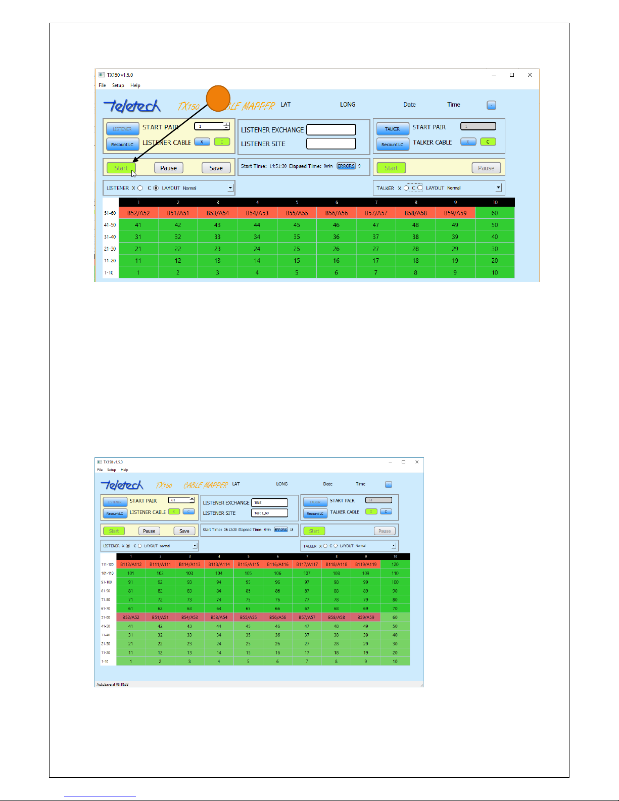
The program should respond after a few seconds with the results of the test. If the cable pair is
terminated correctly the corresponding pair in the results grid will be coloured Green. If there is an
error, the corresponding grid entry will be in Red. If no signal is received on both legs of a pair the
grid entry will be white. The display will constantly update with new results until the ‘Pause” or
“Save” buttons are pressed.
1
2
3
Page 12
12
Fig 8 Testing started and 'live' - showing test results
The work can be saved at this point by clicking the Save button. If there are further pairs to test,
click the Pause button. If you are using the same laptop at both ends, disconnect the laptop to take
to the other end of the cable to change the pair range at the Talker.
If you have tested all of the pairs, complete the location details in the middle of the screen i.e.
Listener Exchange and Listener Site. Then click the Save button. The results will be saved in csv
format to a location on the computer’s hard drive.
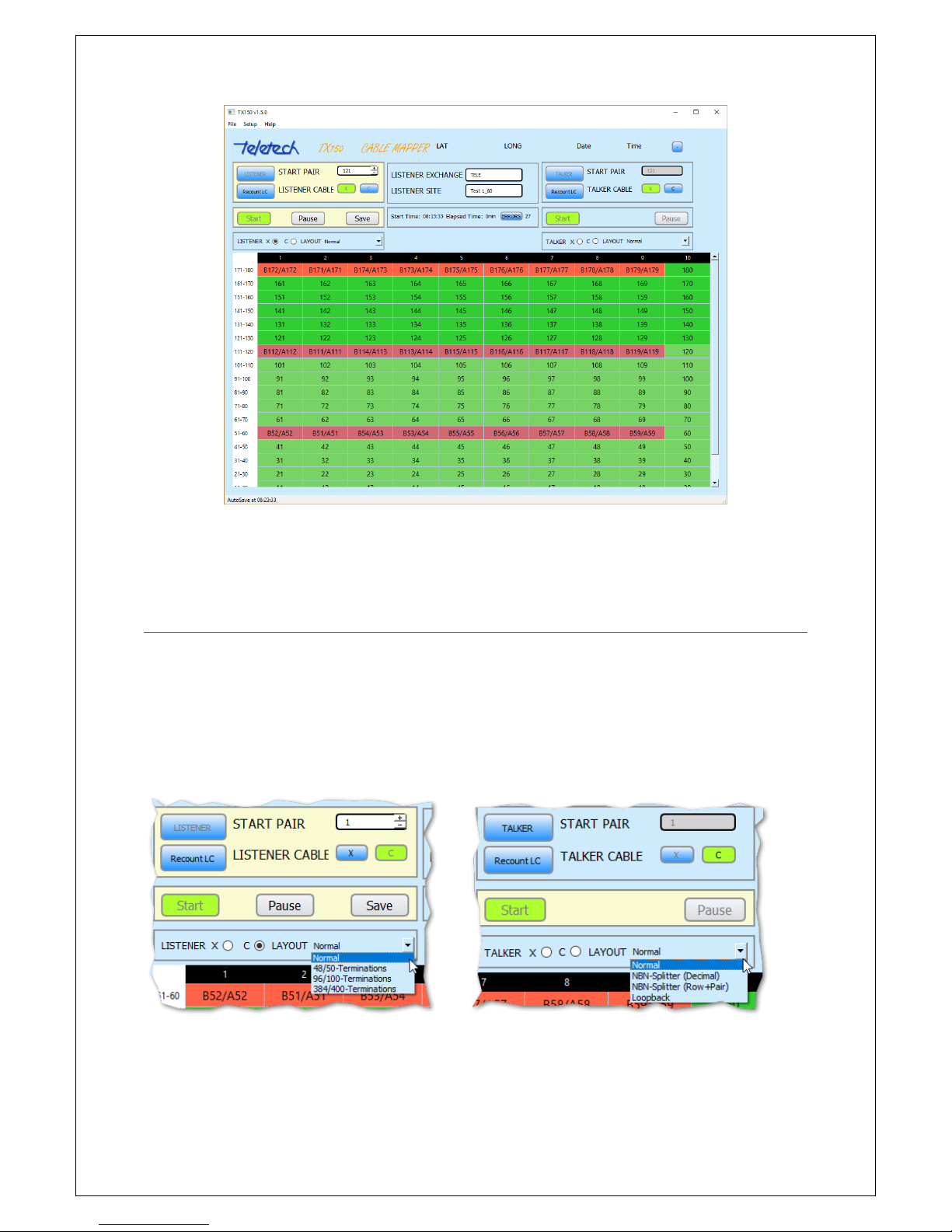
The following two screens show an operator continuing to test more of the pairs after moving the
Line Cards and testing the new ranges. Note the colour changes to indicate the pair range the Line
Cards are connected currently testing.
Fig 9 Continuing testing for the range 61 to 120
4
Page 13
13
Fig 10 Continuing testing for the range 121 to 180
10 TESTING OPTIONS
There are several options when testing the cable terminations. If you are testing the tie cable from
the pillar to the FTTN cabinet, there is a one-to-one correspondence of the pairs at both ends. In
this situation set the Layout options to Normal at both the Talker and Listener.
If you are testing at the 16-pair connectors where the splitters are normally inserted, then set the
Layout at the Talker to NBN-Splitter (Row). You can alternatively choose NBN-Splitter (Decimal)
which shows the Talker Pair Numbers (2 to 768 for a 384-port cabinet).
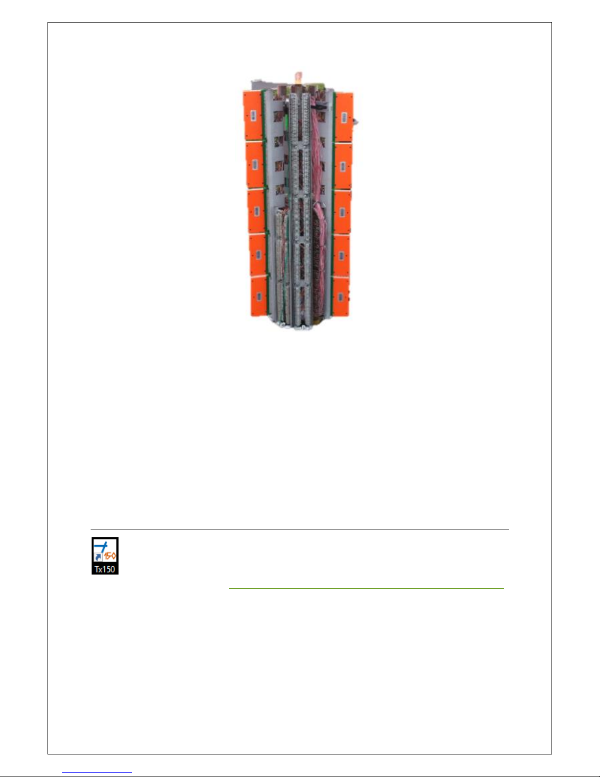
Another layout option is Loopback. This is chosen when testing at the pillar only and you are using
the splitters at the cabinet to connect the X-pairs to the C-pairs. This is usually used for a
preliminary check that the terminations are correct in 384-port cabinets.
Fig 11 Listener Layout Options
Fig 12 Talker Layout Options
Page 14
14
Fig 93 A pillar with 10xQuante 20s in Loopback
At the Listener end there are also several Layout options which determine what pairs are marked as
faults. When testing just the tie cable and there is a one-to-one pair correspondence the Normal
option is chosen.
If you are testing from the 16-pair connectors only 384 of the 400 pairs are connected (384 ports to
400 pair cable). The pairs are usually wired so that 48 pairs are connected to 50 pairs of the cable.
Pairs 49 and 50 are unterminated. Each group of 50 pairs are terminated to 48 ports. In this case
choose 48/50-Terminations. Occasionally the ports are terminated as 96 ports are connected to
every 100 cable pairs (pairs 97-100 are unterminated) or 384 ports are connected to 400 pairs (pairs
385-400 are unterminated). In these cases choose the appropriate termination Layout.
11 TX150 WINDOWS APPLICATION
The application will install the Tx150 icon onto the computers desktop. The application can
be downloaded from Teletech at http://www.teletech.com.au/web?page=Products&category=3#54,
choose TX150 Installer (Installer), the latest version.
11.1 LAYOUT AND POP-UPS
The TX150 Application (App) is divided into two sections, they are; the input and the reporting
sections.
Page 15
15
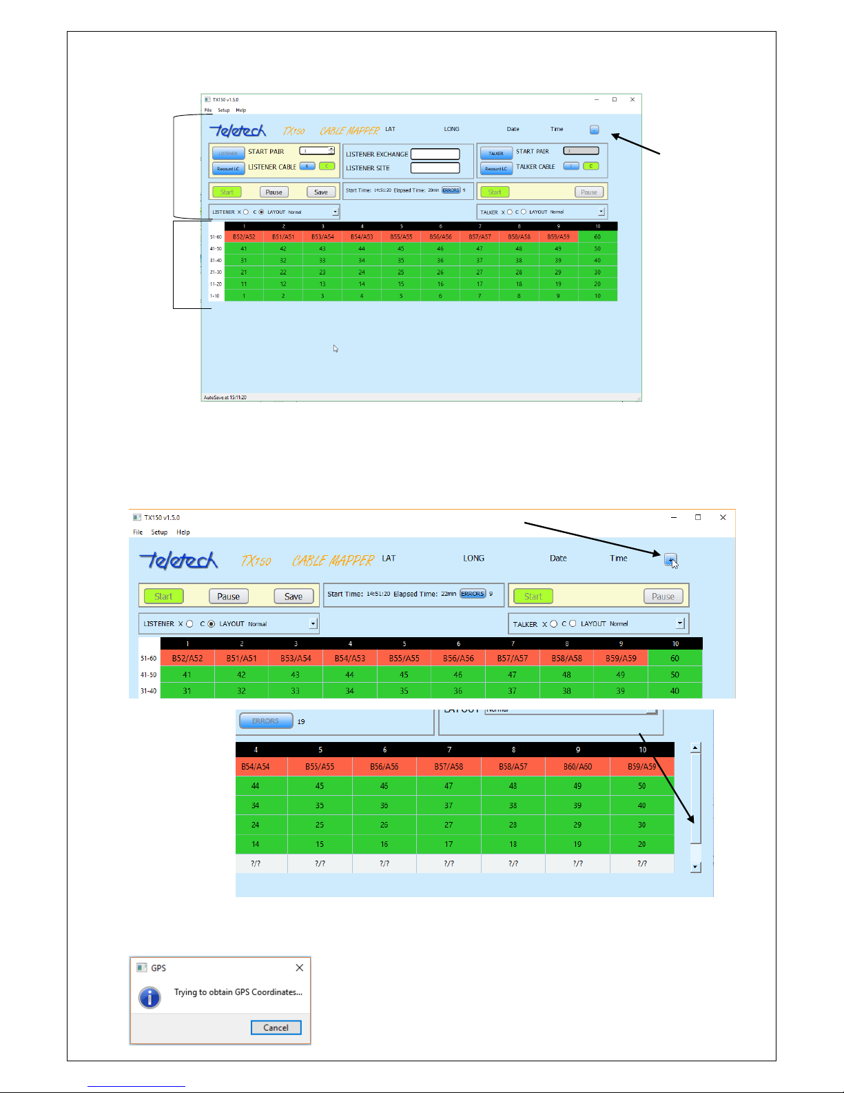
The App has several navigation and user prompt features. For example, the Input section can be
collapsed to increase the display area for the reporting section or if the reporting section rolls over a
page a scroll bar activates.
The App provides feedback on many of the operations. For example, it allows the operator to
bypass obtaining GPS coordinators and advises when GPS cannot be found.
Input
Screen after collapsing
Button to collapse
the Input Section
Scroll bar
Reporting
Page 16
16
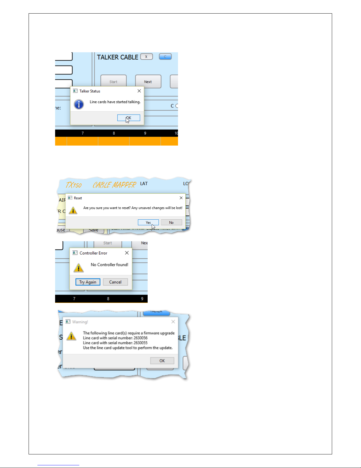
The operator is advised when the Line Cards (LCs) are talking.
The following are examples of warning and messages to the operator.
Warning message after the
‘New Job’ is activated.
When the operator’s TC150
controller was not connected to
the laptop.
A message to warn the Operator that
some Line Cards have out-of-date
firmware.
Page 17
17
11.2 MENU BAR - FILE, SETUP AND HELP
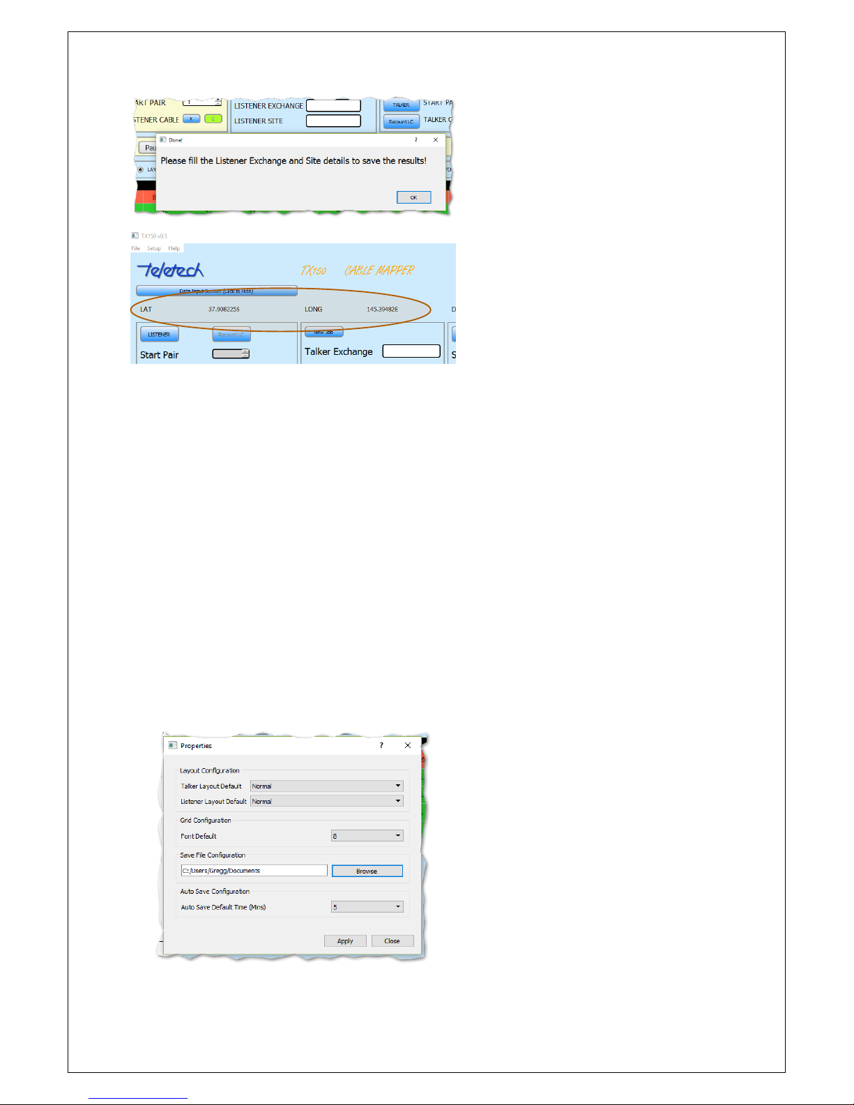
There are various setup and helpful features in File, Setup and Help. The actions and features are:
File:
o Retrieve previously saved jobs (csvs);
o Open the the TX150 Application or as a spreadsheet; and
o Open a new job
Setup, the feature a user can customise are:
o The LAYOUT default option (for example if a user is only performing Loop Back
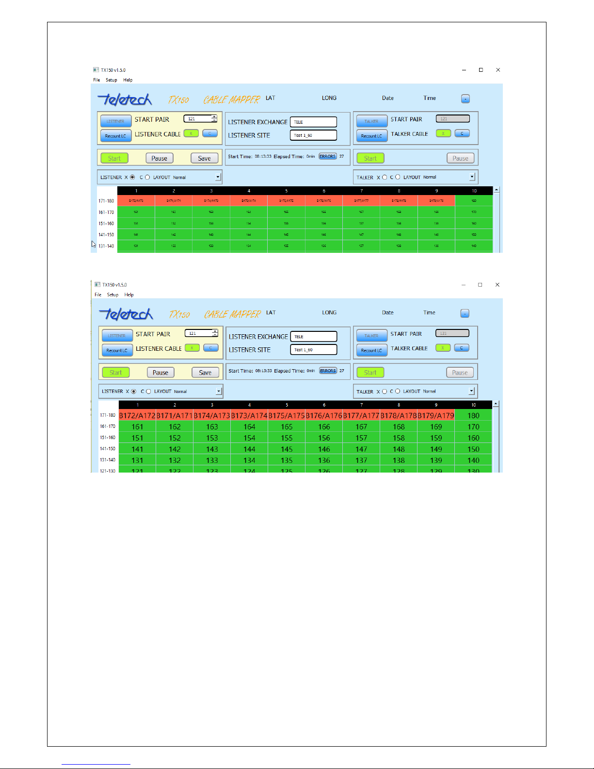
testing they can make it their default);
o Change the size of the results Grid font size;
o Change the location the csv file is saved into;
o Select the time delay between the Auto-saves.
Fig 14 Setup Properties – User customisation
A message to remind the Operator
that the Job details are missing –
after pressing “Finish”.
The GPS co-ordinates are displayed
and stored in the csv after the Job
is saved (or autosaved).
Page 18
18
Fig 15 Font size of 8 point selected
Fig 16 Font size of 20 point selected
Help;
o The Operator’s Manual is available as a pdf (this can be opened while the TX150 App
is in operation and a user can tab between the Manual and the App);
o The version of the Application.
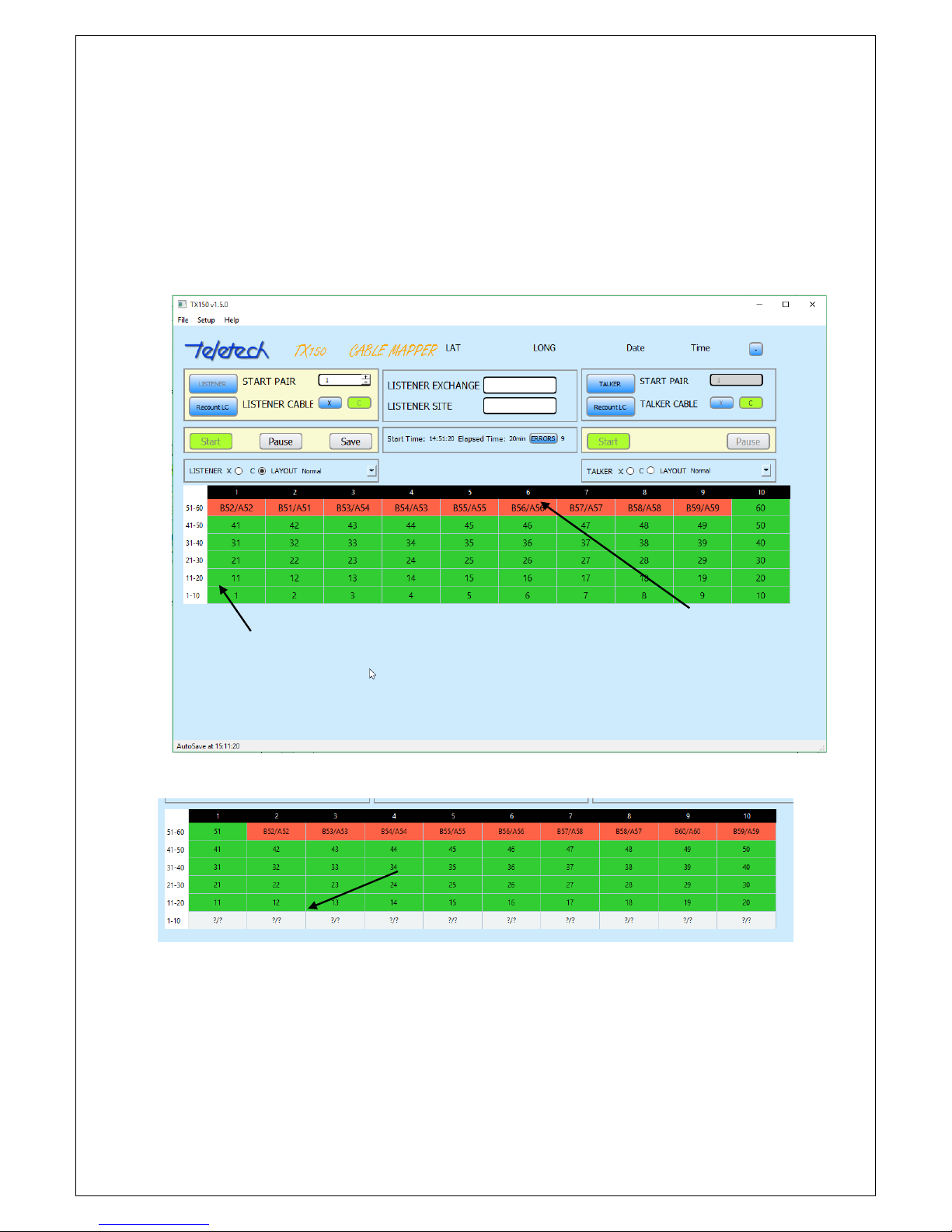
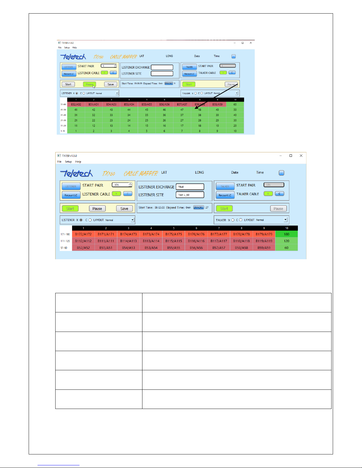
11.3 RESULTS COLOUR SCHEME
The App uses a colour scheme in the Reporting section to provide visual guidance to the Operator,
the colours used are:
Orange - the correct locations of the attached Line Cards is displayed;
Green - the cable connections are correct and are being continuously monitored by the
TX150;
Page 19
19
Light Green – the connections are correct but the TX150 is no longer monitoring (usually as
Pause is activated;
White – there is no signal at the Line Card;
Grey – same as above but monitoring is Paused;
Red -an error has been detected in the cabling; and
Light Red - same as above but monitoring is Paused.
Cabling errors
Rows are laid out to mimic the
cabinet/pillar layout. Lowest number
at the bottom.
10 pair LC removed
Page 20
20
11.4 APP TITLES & BUTTON MEANINGS
The meaning of the Labels and the Buttons is in the following tables:
Button Title
Meaning/Action
Date/Time
Current time (obtained by the GPS). Stops updating once job has finished
Start Time
Time job was started, (obtained by the GPS).
Elapsed time
Duration of current job in minutes
LAT
Latitude obtained by the GPS
LONG
Longitude obtained by the GPS
After the ‘Pause’ button is
activated the reporting section
changes colour to indicate the
results are not ‘live’
Page 21
21
Start Pair
The starting pair the Line Card is connected into
LISTENER CABLE (X) OR (C)
Choose the cable the Line Cards are connected to (X or C)
TALKER CABLE (X) or (C)
Choose the cable the Line Cards are connected to ( X or C). Not used for
16-pair Line Cards which connect to both
TALKER LAYOUT
Option for the user to select the type of testing
Normal
One to one correspondence for pair numbers
NBN-Splitter (Decimal)
Sets Listener to correct format when testing at the NBN Splitters. Results
are displayed with the pair number of the Splitter pair (2 to 768)
NBN-Splitter (Row +
Pair)
As above but pair numbers are displayed as Terminal Block Row and Pair
number
Loopback
Sets Listener to correct format when testing at the pillar with the X pairs
looped to the corresponding C pairs
LISTENER LAYOUT
Sets the format for the Listener to display the correct fault code with
different termination layouts
Normal
One to one correspondence for pair numbers
48/50 - Terminations
Used when pairs 49 and 50 are not wired from the Node to the Pillar
96/100 – Terminations
Used when pairs 97-100 are not wired from the Node to the Pillar
384/400 - Terminations
Used when pairs 385-400 are not wired from the Node to the Pillar
Talker Exchange/Site
Detail to be input by the operator to uniquely identify the Node/Pillar
being tested
Listener Exchange/Site
As above
The functions; File, Setup and Help enable the Operator to retrieve previous Jobs, change the default
location of the saved work and information about the App (including this manual). Action Button
Button Title
Action
TALKER
Commands the Controller to operate as a Talker
Page 22
22
LISTENER
Commands the Controller to operate as a Listener
Recount LC
Instructs the program to refresh and count how many Line Cards are
connected to the TC150 Controller
Start
Either, starts the Talker Line Cards or starts the reporting for the
Listener.
Pause
Will halt testing at the Listener so test results don’t change until Start or
Finish is pressed.
Save
Save the test results to a csv file and close the application
Errors
Will filter the displayed grid so only rows that contain errors are
displayed in the report section
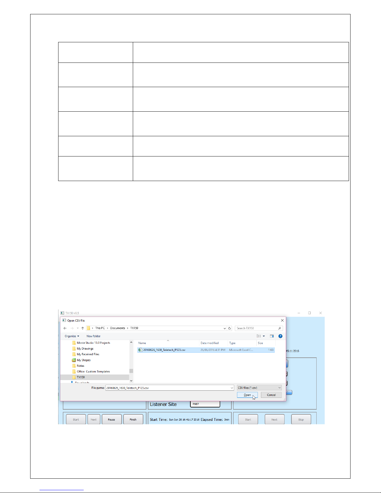
11.5 SAVING YOUR WORK (CSV)
After the Operator has clicked on the ‘Finish’ button the details of the Job are saved to a comma
separated value (CSV) file. The file name is derived from Date; YYYYMMDD, Time; HHmm and
Listener Exchange and Site. A typical file name will look like 20160626_1630_Teletech_P123,
therefore, it is possible to save multiple times at the same site and not overwrite previously saved
files. A suggestion is to include the starting pair number in the file number. Using this method it
makes it easy to load back the correct file into the App.
The Setup function enables an operator to set the default location to save the CSVs files. If a TX150
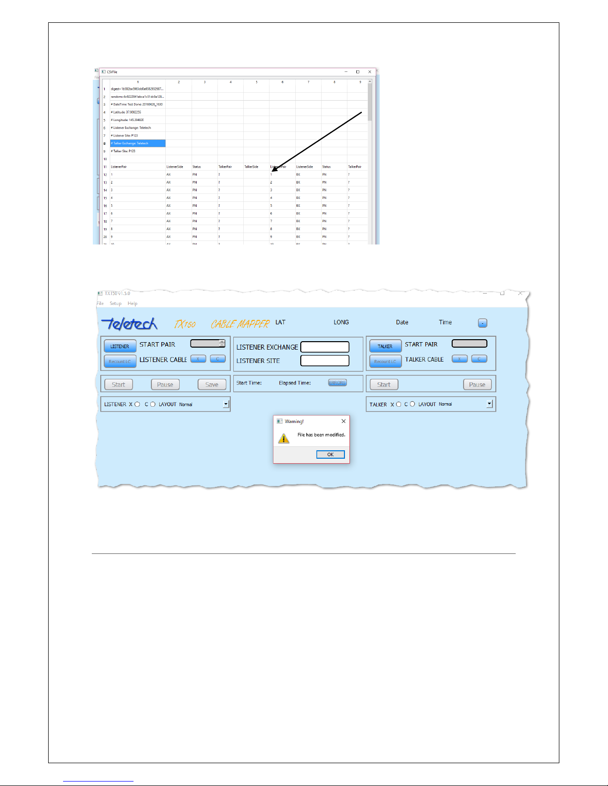
CSV file is edited in any way the App will identify that it has been changed.
After a CSV has been saved it can be retrieved using the File function, either within the APP (Open In
App) or as a CSV (Open In App). The CSV file is proof of TX150 testing and whether the cable was
terminated correctly (or not).
Page 23
23
If the csv file is modified in anyway (eg. a pair number is changed in a cell), the TX150 App will
display a Warning that the, “File has been modified” and will not display the file.
12 TERMINATION ERRORS
The TX150 will detect the following termination errors, they are:
Pair connections;
Split pairs;
Inverted A/B
Open Circuits; and
Short circuits.
The Pair Status flags appearing in the CSV file are:
CSV of a Job
Page 24
24
Status
Meaning
N
No signal received (Open/short)
D
Receiving in progress
S
X/C Side mismatch
P
Pair number mismatched
V
A/B inVerted
F
Interference/intermittent fault
‘-‘
No error. All data items present and matched
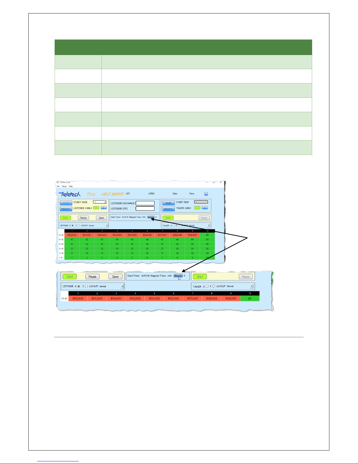
Cabling errors are displayed as red cells within the Reporting section.
Use the ‘Errors’ button to filter and only show rows with cabling errors.
13 TIPS
The following are a list of tips to make using the TX150 application easier:
Save your work frequently. Every 100 pairs is recommended. At least until the operator has
become very proficient with the use of this product;
Use the ‘Pause’ button frequently. Preferably as soon as the operator has the results
displayed;
Ensure that the Line Cards are correctly lined up when plugged into the terminal blocks. This
is particularly important when using R&M 16s, if one R&M16 is up-side down, then it will not
talk to the Listener. Look at the LEDs, they must all be in alignment;
Errors button filtering
Page 25

25
For R&M 16s, pair 1 is at the top. Refer to the legend in the Node;
When testing at the Splitters, test both X and C cables at the Pillar before moving the Line
Cards at the Splitter; and
Check for and remove shards of wire which are occasionally left in the terminal blocks or
gently wiggle the R&M Line Cards till they connect to the termination contacts;
If you get the same pair number - cross talk from the Talker is a possible cause. The solution
is to re-terminate and it should correct the error – note that the TX150 is more sensitive
than your multimeter
Add the pair number to the site information when making frequent saves. This makes the
file name more recognisable if it needs to be re-displayed in the App.
14 TECHNICAL INFORMATION
Line Card
Types: R&M VS Compact 10 pair; R&M 16 pair (X/C); R&M 20 pair; Quante SID-C 10 pair;
Quante 20 pair; Krone CSA-PLUS series 2 10 pair; Krone HD180 10 pair; 3M 20 pair
Line Cards per Controller: Maximum of 60 line cards
Operating Distance: 300-500m maximum cable between Line Cards
Controller
Battery Operated: 5 volts
Battery Type: rechargeable Li (USB charging). Power Bank (NB* many commercial power
banks are not suitable to power the TX150, use only the power bank provided.
Battery Capacity: 20 hours minimum operating time between charging (full charge)
Page 26
26
Quality
ISO 9001
15 WARRANTY
Teletech Pty Ltd provides 12 month warranty for the TX150. The warranties do not cover any
product that has been misused, abused, improperly or poorly used or disassembled. The warranty
covers any product that becomes defective under reasonable normal usage as determined solely by
Teletech Pty Ltd.
Items returned for repair or replacement shall be shipped with a copy of the dated invoice, freight
charges prepaid to:
Teletech Pty Ltd
Unit 8
2-6 Apollo Court,
Blackburn 3130 VICTORIA
AUSTRALIA
Tel:
+61
3 9877 3033
Fax:
+61
3 9878 6322
For sales and support
Email…. [email protected]
www.teletech.com.au
MADE IN AUSTRALIA
Copyright Teletech Pty. Ltd. 2017 ©
Document Version 1.5.0
Innovation Solutions for the telecommunications industry
 Loading...