

Page 1

TDS20065
Quick Installation Guide
Page 2
TDS20065
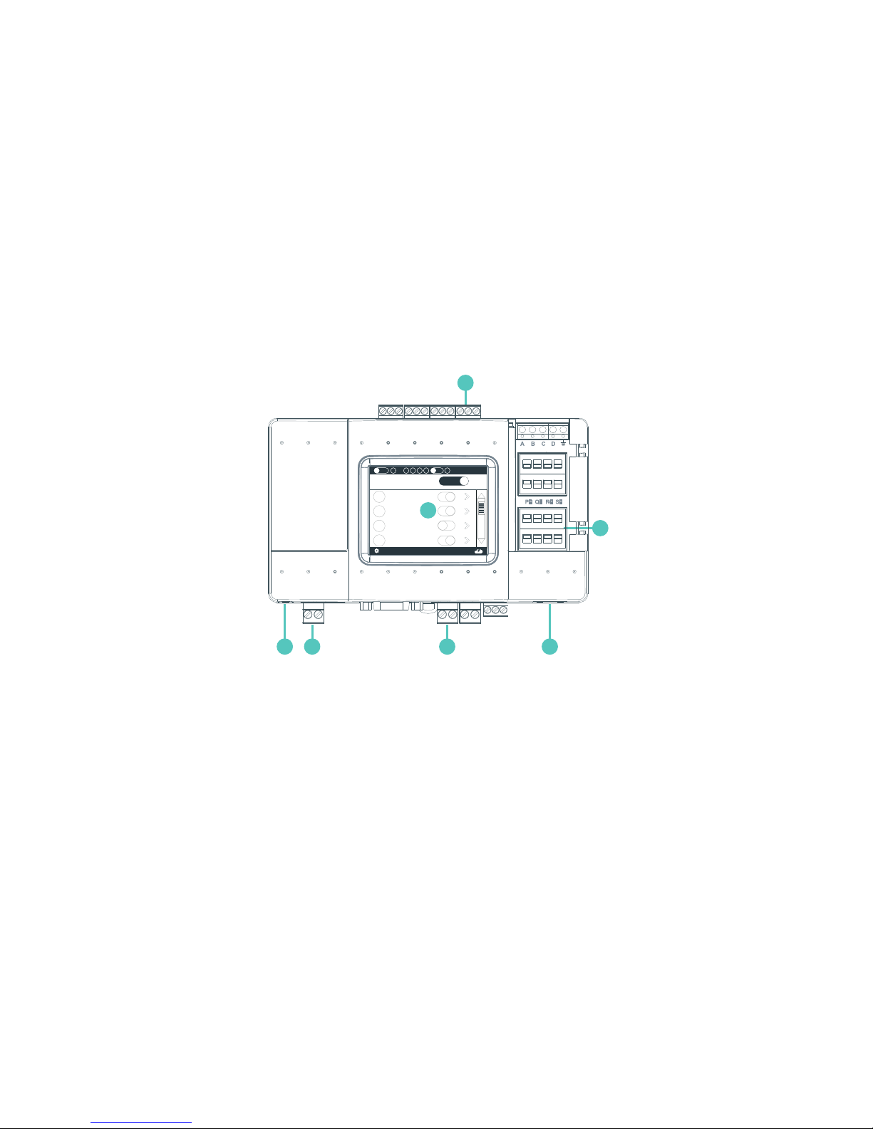
L8 – HVAC Line 8 (USB Host)
Power
L1 – HVAC Line 1
Ethernet Port
L7 – HVAC Line 7
DIP Switches P, Q, R, S
LCD Touch Screen
1 2 3 4
6
5
7
All Units
21 L1.101
23 L1.102
25 L1.103
25 L7.101
MACADDR00001
L6 L8L5L4L3L2
192.168.0.1
cj
9/10
LG
PQW
All O
1
2
3
4
5
6
7
Page 3
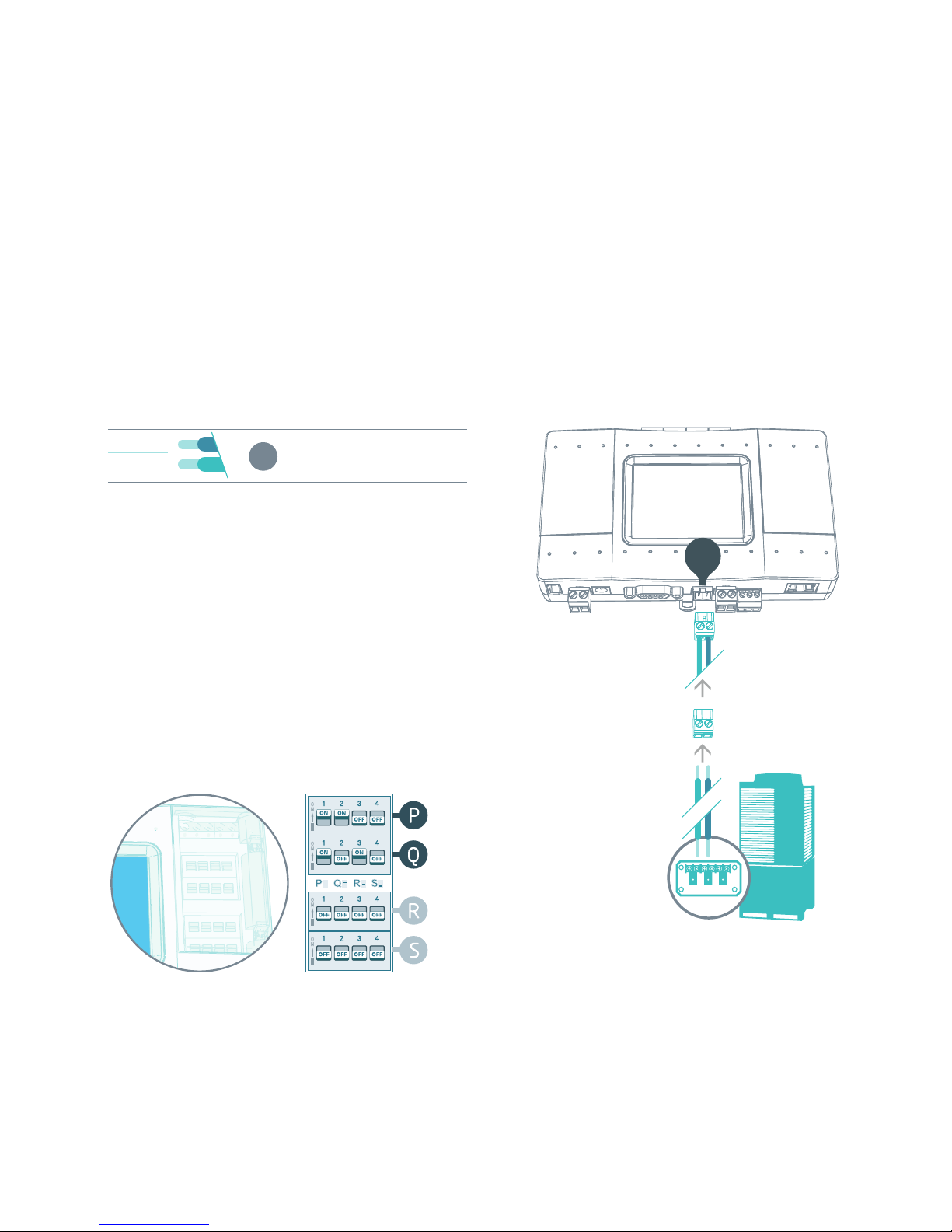
HVAC Daikin VRV — on L1
1
HVAC Communication Terminals
Connect to the communication terminals on
the HVAC equipment:
HVAC communication terminal’s names*
F1
Daikin **
Max. 64 indoor units
F2
* For Heat Recovery systems the connection is at
oudoor units only.
* Polarity is not required on the HVAC
communication line.
** Centralized (group) address required.
2
Connecting to the line plug
Secure the cables in the L1 line plug.
3
Plugging to the TDS20065
Insert the plug in to the TDS20065 L1
socket
4
Check DIP Switches are set correctly
Dip switches setup for VRV HVAC system on L1
DK
Daikin HVAC Terminal
L1
4
3
2
1
Page 4
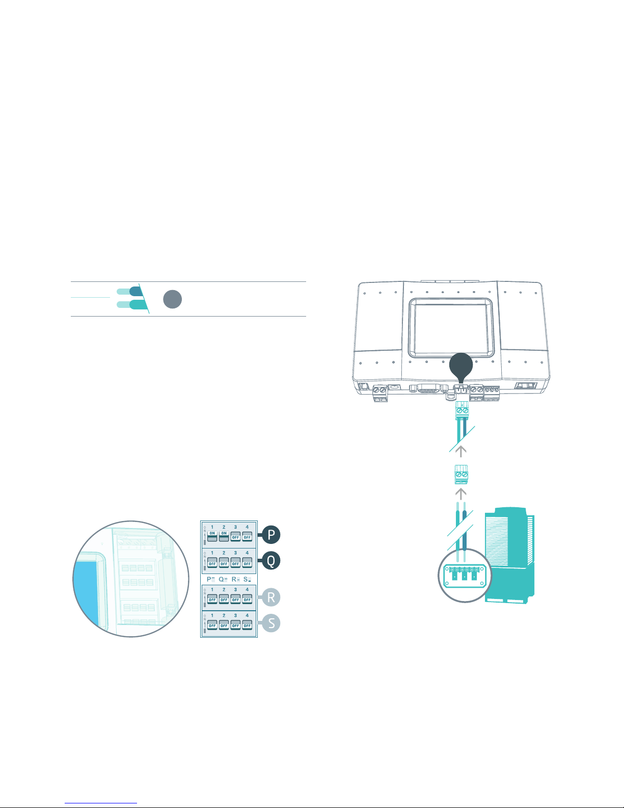
HVAC Mitsubishi Electric VRF — on L1
1
HVAC Communication Terminals
Connect to the communication terminals on
the HVAC equipment:
HVAC communication terminal’s names*
M1
Mitsubishi Electric
Max. 50 indoor units
M2
* For Heat Recovery systems the connection is at
outdoor units only.
* Polarity is not required on the HVAC
communication line.
2
Connecting to the line plug
Secure the cables in the L1 line plug.
3
Plugging to the TDS20065
Insert the plug in to the TDS20065 L1
socket
4
Check DIP Switches are set correctly
Dip switches setup for VRF HVAC system on L1
ME
L1
4
3
2
1
Mitsubishi Electric HVAC Terminal
Page 5
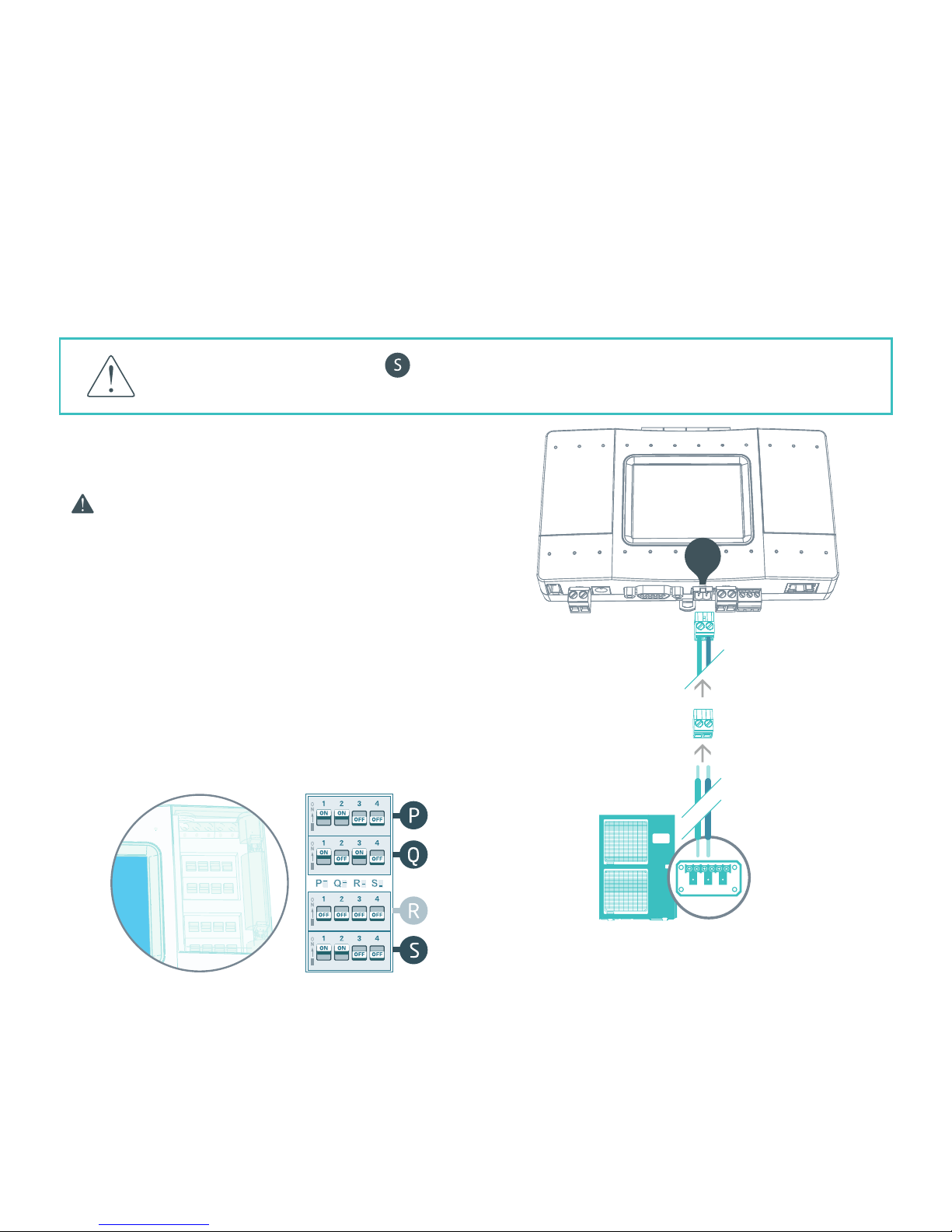
HVAC Daikin Non-VRV — on L1
For Daikin Non-VRV equipment, DC voltage supply
by TDS20065 might be required for proper
operation.
Before enabling DC output from TDS20065 make sure
there is no DC voltage on HVAC communication line.
1
Measure DC voltage on HVAC communication
line L1
2
If no DC voltage . Daikin 14-16V DC change
the dip switches as shown below
3
Turn ON the power for TDS20065 and
connect it to HVAC line.
4
Connect to the communication terminals on
the HVAC equipment and secure the cables in
the L1 line plug.
5
Insert the plug in to the TDS20065 L1
socket.
Daikin Non-VRV HVAC Terminal
Changing the dip switches
, while DC voltage is present on L1, may damage
the TDS20065.
L1
2
1
4
3
5
Page 6

HVAC Mitsubishi Electric Non-VRF — on L1
For Mitsubishi Electric Non-VRF equipment,
DC voltage supply by TDS20065 might be
required for proper operation.
Make sure TDS20065 is disconnected
from power and HVAC line.
1
Measure DC voltage on HVAC communication
line L1
2
If no DC voltage . Mitsubishi 28-30V DC
change the dip switches as shown below
3
Turn ON the power for TDS20065 and
connect it to HVAC line.
4
Connect to the communication terminals on
the HVAC equipment and secure the cables in
the L1 line plug.
5
Insert the plug in to the TDS20065 L1
socket.
Mitsubishi Non-VRF HVAC Terminal
Changing the dip switches
, while DC voltage is present on L1, may damage
the TDS20065.
L1
2
1
4
3
5
Page 7

1
HVAC Communication Terminals
Connect to the communication terminals on
the HVAC equipment:
HVAC communication terminal’s names*
U1
Panasonic / Sanyo
Max. 64 indoor units
U2
* For Heat Recovery systems the connection is at
outdoor units only.
* Polarity is not required on the HVAC
communication line.
2
Connecting to the line plug
Secure the cables in the L1 line plug.
3
Plugging to the TDS20065
Insert the plug in to the TDS20065 L1
socket
4
Check DIP Switches are set correctly
Dip switches setup for VRF HVAC system on L1
PN
HVAC Panasonic/Sanyo VRF — on L1
Panasonic / Sanyo HVAC Terminal
L1
4
3
2
1
Page 8

1
HVAC Communication Terminals
Connect to the communication terminals on
the HVAC equipment:
HVAC communication terminal’s names*
U1
Toshiba
Max. 64 indoor units
U2
* For Heat Recovery systems the connection is at
outdoor units only.
* Polarity is not required on the HVAC
communication line.
2
Connecting to the line plug
Secure the cables in the L1 line plug.
3
Plugging to the TDS20065
Insert the plug in to the TDS20065 L1
socket
4
Check DIP Switches are set correctly
Dip switches setup for VRF HVAC system on L1
TO
HVAC Toshiba VRF — on L1
Toshiba HVAC Terminal
L1
4
3
2
1
Page 9

HVAC Hitachi (JCI) VRF — on L1
1
HVAC Communication Terminals
Connect to the communication terminals on
the HVAC equipment:
HVAC communication terminal’s names*
1
Hitachi
Max. 160 indoor units
2
* For Heat Recovery systems the connection is at
outdoor units only.
* Polarity is not required on the HVAC
communication line.
2
Connecting to the line plug
Secure the cables in the L1 line plug.
3
Plugging to the TDS20065
Insert the plug in to the TDS20065 L1
socket
4
Check DIP Switches are set correctly
Dip switches setup for VRF HVAC system on L1
HT
Hitachi (JCI) HVAC Terminal
L1
4
3
2
1
Page 10

HVAC York (US) VRF — on L1
1
HVAC Communication Terminals
Connect to the communication terminals on
the HVAC equipment:
HVAC communication terminal’s names*
1
York (US)
Max. 164 indoor units
2
* For Heat Recovery systems the connection is at
outdoor units only.
* Polarity is not required on the HVAC
communication line.
2
Connecting to the line plug
Secure the cables in the L1 line plug.
3
Plugging to the TDS20065
Insert the plug in to the TDS20065 L1
socket
4
Check DIP Switches are set correctly
Dip switches setup for VRF HVAC system on L1
YK
York (US) HVAC Terminal
L1
4
3
2
1
Page 11

L1
4
3
2
1
HVAC York VRF — on L1
1
HVAC Communication Terminals
Connect to the communication terminals on
the HVAC equipment:
HVAC communication terminal’s names*
P
York
Max. 64 indoor units
Q
* For Heat Recovery systems the connection is at
outdoor units only.
* Polarity is not required on the HVAC
communication line.
2
Connecting to the line plug
Secure the cables in the L1 line plug.
3
Plugging to the TDS20065
Insert the plug in to the TDS20065 L1
socket
4
Check DIP Switches are set correctly
Dip switches setup for VRF HVAC system on L1
YK
York HVAC Terminal
Page 12

HVAC Haier VRF — on L1
1
HVAC Communication Terminals
Connect to the communication terminals on
the HVAC equipment:
HVAC communication terminal’s names*
P
Haier
Max. 64 indoor units
Q
* For Heat Recovery systems the connection is at
outdoor units only.
* Polarity is not required on the HVAC
communication line.
2
Connecting to the line plug
Secure the cables in the L1 line plug.
3
Plugging to the TDS20065
Insert the plug in to the TDS20065 L1
socket
4
Check DIP Switches are set correctly
Dip switches setup for VRF HVAC system on L1
HA
Haier HVAC Terminal
L1
4
3
2
1
Page 13

HVAC Mitsubishi Heavy VRF — on L7
1
HVAC Communication Terminals
Connect to the communication terminals on
the HVAC equipment:
HVAC outdoor or indoor
A
Mitsubishi Heavy
(Max. 128 indoor units)
B
2
Connecting to the line plug
Secure the cables in the L7 line plug.
3
Plugging to the TDS20065
Insert the plug in to the TDS20065 L7
socket
4
Check DIP Switches are set correctly
Dip switches setup for VRF HVAC system on L7
MH
Mitsubishi Heavy HVAC Terminal
L7
A B
4
3
2
1
Page 14

HVAC LG VRF — on L7
1
HVAC Communication Terminals
Connect to the communication terminals on
the HVAC equipment:
HVAC outdoor or indoor
InterA
LG
(Max. 128 indoor units)
InterB
2
Connecting to the line plug
Secure the cables in the L7 line plug.
3
Plugging to the TDS20065
Insert the plug in to the TDS20065 L7
socket
4
Check DIP Switches are set correctly
Dip switches setup for VRF HVAC system on L7
LG
LG HVAC Terminal
L7
A B
4
3
2
1
Page 15

HVAC Gree VRF — on L7
1
HVAC Communication Terminals
Connect to the communication terminals on
the HVAC equipment:
HVAC outdoor only
A
Gree
Max. 16 indoor units
B
2
Connecting to the line plug
Secure the cables in the L7 line plug.
3
Plugging to the TDS20065
Insert the plug in to the TDS20065 L7
socket
4
Check DIP Switches are set correctly
Dip switches setup for VRF HVAC system on L7
GR
Gree HVAC Terminal
L7
A B
4
3
2
1
Page 16

HVAC Midea VRF — on L7
Midea HVAC Terminal
L7
A B
4
3
2
1
1
HVAC Communication Terminals
Connect to the communication terminals on
the HVAC equipment:
HVAC outdoor only
X
Midea
Max. 64 indoor units
Y
E
2
Connecting to the line plug
Secure the cables in the L7 line plug.
3
Plugging to the TDS20065
Insert the plug in to the TDS20065 L7
socket
4
Check DIP Switches are set correctly
Dip switches setup for VRF HVAC system on L7
MD
Page 17

HVAC Samsung VRF — on L7
1
HVAC Communication Terminals
Connect to the communication terminals on
the HVAC equipment:
HVAC outdoor only
R1
Samsung
Max. 64 indoor units
R2
2
Connecting to the line plug
Secure the cables in the L7 line plug.
3
Plugging to the TDS20065
Insert the plug in to the TDS20065 L7
socket
4
Check DIP Switches are set correctly
Dip switches setup for VRF HVAC system on L7
SM
Samsung HVAC Terminal
L7
A B
4
3
2
1
Page 18

L7
A B
4
3
2
1
HVAC Trane VRF — on L7
1
HVAC Communication Terminals
Connect to the communication terminals on
the HVAC equipment:
HVAC outdoor only
X
Trane
Max. 64 indoor units
Y
E
2
Connecting to the line plug
Secure the cables in the L7 line plug.
3
Plugging to the TDS20065
Insert the plug in to the TDS20065 L7
socket
4
Check DIP Switches are set correctly
Dip switches setup for VRF HVAC system on L7
TR
Trane HVAC Terminal
Page 19

HVAC Trane (US) VRF — on L7
1
HVAC Communication Terminals
Connect to the communication terminals on
the HVAC equipment:
HVAC outdoor only
R1
Tane (US)
Max. 64 indoor units
R2
2
Connecting to the line plug
Secure the cables in the L7 line plug.
3
Plugging to the TDS20065
Insert the plug in to the TDS20065 L7
socket
4
Check DIP Switches are set correctly
Dip switches setup for VRF HVAC system on L7
TR
Trane (US) HVAC Terminal
L7
A B
4
3
2
1
Page 20

HVAC Kentatsu VRF — on L7
1
HVAC Communication Terminals
Connect to the communication terminals on
the HVAC equipment:
HVAC outdoor only
X
Kent atsu
Max. 64 indoor units
Y
E
2
Connecting to the line plug
Secure the cables in the L7 line plug.
3
Plugging to the TDS20065
Insert the plug in to the TDS20065 L7
socket
4
Check DIP Switches are set correctly
Dip switches setup for VRF HVAC system on L7
KN
Kentatsu HVAC Terminal
L7
A B
4
3
2
1
Page 21

Lorem ipsum
HVAC Chigo VRF — on L7
1
HVAC Communication Terminals
Connect to the communication terminals on
the HVAC equipment:
HVAC outdoor only
X
Chigo
Max. 64 indoor units
Y
E
2
Connecting to the line plug
Secure the cables in the L7 line plug.
3
Plugging to the TDS20065
Insert the plug in to the TDS20065 L7
socket
4
Check DIP Switches are set correctly
Dip switches setup for VRF HVAC system on L7
CH
Chigo HVAC Terminal
L7
A B
4
3
2
1
Page 22

1
HVAC Communication Terminals
Connect to the communication terminals on
the HVAC equipment:
HVAC outdoor only
G1
Gree GMV5
Max. 64 indoor units
G2
2
Connecting to the TDSxxx
A USB Network Interface adapter is required for
connecting up to two Gree GMV5 VRF lines.
Please contact support.
This adapter includes a CAN bus 120 Ω resistor
3
Plugging to the TDS20065
Insert the plug in to the TDS20065 L8
(USB)
4
Check DIP Switches are set correctly
3rd dip switch should be ON on the 1st subline
of Gree GMV5.
GR
L8
HVAC Gree GMV5 VRF — on L8
Gree GMV5 HVAC Terminal
4
3
2
1
1 2 3 4 5 6
ON
OFF OFFOFFOFF OFF
Page 23

HVAC Fujitsu VRF — on L8
1
HVAC Communication Terminals
Connect to the communication terminals on
the HVAC equipment:
HVAC communication terminal names:
X1
Fujitsu
Max. 128 indoor units
X2
2
Connecting to the TDS20066 adapter
TDS20066 USB Network Interface (TP/FT-10)
adapter is required for connecting to Fujitsu
VRF.
3
Connect Echelon via USB Extension cable
Connect the USB Extension cable (A-Male to
A-Female) to the adapter.
4
Plug in to the TDS20065 L8
Insert the USB cable in to the L8 USB host.
FJ
L8
Fujitsu HVAC Terminal
3
2
1
4
Page 24

HVAC Rheem VRF — on L8
1
HVAC Communication Terminals
Connect to the communication terminals on
the HVAC equipment:
HVAC communication terminal names:
X1
Rheem
Max. 128 indoor units
X2
2
Connecting to the TDS20066 adapter
TDS20066 USB Network Interface (TP/FT-10)
adapter is required for connecting to Rheem
VRF.
3
Connect Echelon via USB Extension cable
Connect the USB Extension cable (A-Male to
A-Female) to the adapter.
4
Plug in to the TDS20065 L8
Insert the USB cable in to the L8 USB host.
RH
L8
Rheem HVAC Terminal
3
2
1
4
Page 25

CoolMasterNet installation complete
CoolMasterNet Unit screen
After successful installation, units screen will show
all the detected indoor units and their statuses.
Active HVAC line (DK 9/10) (Groups/Units)
Inactive HVAC line
All ON/OFF operation button
Scrollbar
Connected indoor unit with it’s address and
Set-Point temperature indication.
Service settings button
TDS20065 MAC address
TDS20065 IP address
CoolRemote connectivity status
Connected - Communicating
Connected - Idle
Disconnected - with error code
www.coolautomation.com/support/coolmasternet
Firmware update FAQ www.coolautomation.com/support/faq/coolmasternet
1
2
3
4
5
6
7
8
9
10
Page 26

Mounting on a DIN rail
1
Place the device mounting
feet on the DIN rail
To unmount,
pull the mounting
lock down.
2
Push on the lower part of the
device onto the the DIN rail
to lock it in place
Page 27

40
Mounting on a wall
 Loading...