

TeleSwivel 210, 210 DH, 210 AP Owner's Manual
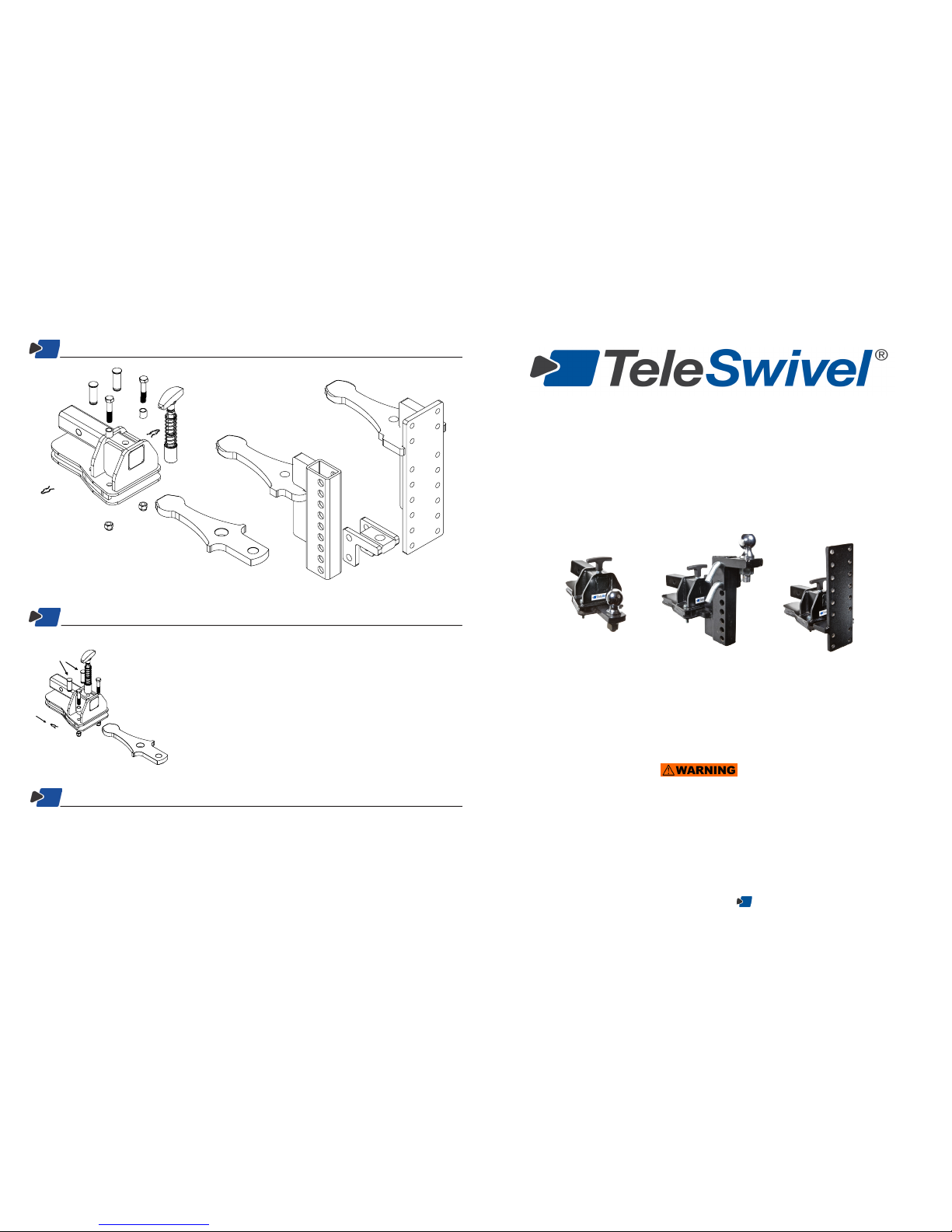
Parts
The TeleSwivel® 210 units are all backed by a limited 2-year warranty. For full details about the
warranty please visit teleswivel.com or email info@teleswivel.com.
Thank you for purchasing a
TeleSwivel
®
210 brand hitching system - the fastest, easiest, and safest
way to connect a trailer to a tow vehicle!
Your TeleSwivel
®
is designed and built to the highest
standards to provide years of trouble-free towing.
Owner’s Manual for
TeleSwivel
®
210 Series
(919) 246-9249 teleswivel.com
TeleSwivel
®
210 APTeleSwivel
®
210 DHTeleSwivel
®
210
Service & Repair
If you need service or replacement parts, please contact us:
Web: teleswivel.com
E-mail: info@teleswivel.com
Phone: (919) 246-9249
(A)
A. Cassette
B. Clips
C. Stop Pins
D. Locking Pin Assembly
E. Probe Options
F. Bolt
G. Bushing
H. Lock Nut
(B)
(B)
(C)
(D)
(F)
(F)
(G)
(E - standard)
(H)
(E - Drop Hitch)
(E - Accessory Plate)
Maintenance & Storage
Periodic cleaning and lubrication will enable you to enjoy your TeleSwivel® for many years.
1. Remove the locking clips (ref A); the stop pins (ref B) will pull out from the top of the cassette.
2. Remove the probe (ref C) from the cassette.
3. Clean with soap and water, or a degreasing agent. You may nd a pressure washer to be
helpful in cleaning out the inside of the cassette. Ensure probe and inside of cassette are dry.
4. Lubricate both sides of the probe with white lithium grease.
5. Place the probe back in the case. Replace the stop pins (insert them from the top of the case)
and secure with locking clips.
6. Do not operate without stop pins securely in place.
(A)
(C)
(B)
NOTE for TS 210 AP and DH owners: You may re-insert the accessory probes
in the reverse position to provide an additional drop/rise capability.
(E - Drop Hitch ball mount)
MAXIMUM GROSS TRAILER
WEIGHT: 10,000 LBS.
MAXIMUM TONGUE WEIGHT:
1,000 LBS.
DO NOT EXCEED THE CAPACITY OF THIS
HITCH OR THE VEHICLE TOW RATING AS
SPECIFIED IN YOUR VEHICLE OWNER’S
MANUAL
FAILURE TO FOLLOW
OPERATING INSTRUCTIONS
COULD RESULT IN SERIOUS
INJURY OR DEATH
This tow-bar complies with the requirements of
the Federal Motor Carrier Safety Administration
Manufactured by TeleSwivel, LLC.
Installation
Safety Guidelines
1. WARNING: Do not exceed the towing capacity of your tow vehicle. Check the owner’s manual for your vehicle
for the manufacturer’s recommendations.
2. WARNING: Never use the TeleSwivel® hitching system without both stop pins securely inserted and clipped in
place. Failure to do so could result in serious injury or death if the trailer becomes disconnected from the hitch
system.
3. WARNING: Do not exceed the tongue weight limits for your trailer or hitch. Always load your trailer properly.
4. WARNING: Do not tow with the TeleSwivel® in the extended position to avoid damage to the TeleSwivel® probe.
5. Use wheel chocks to keep your trailer in place when connecting tow vehicle.
6. Connect safety chains whenever you tow.
7. Always make the electrical connection for trailer lights (and brakes, if your trailer is so equipped).
(A)
(B)
(C)
Troubleshooting
PROBLEM LIKELY CAUSE SOLUTION
The TeleSwivel® probe is not
functioning smoothly
Dirt or other possible contamination is
inside the case
Clean the TeleSwivel® following the instructions
above
The TeleSwivel® locking pin
will not seat back into locked
position
Dirt or other possible contamination is
on the locking pin or in the locking pin
hole
Clean the TeleSwivel® following the instructions
above
The TeleSwivel® probe will not
retract back into cassette
A. The tongue weight of the trailer is too
high.
B. Probe is misaligned due to steep terrain or severe angle.
C. Your trailer brakes may be engaging.
A. Reload the trailer with the weight mainly over
the trailer axle.
B. Drive vehicle to a surface that is more level
and align vehicle & trailer before locking.
C. Chock the trailer and back up to lock.
The TeleSwivel® probe is
jammed
Possible damaged or bent TeleSwivel®
probe due to operating in the extended
position
Contact TeleSwivel® technical support
Your TeleSwivel® hitching system should provide years of problem-free service. Occasionally, however, some incidents may
occur.
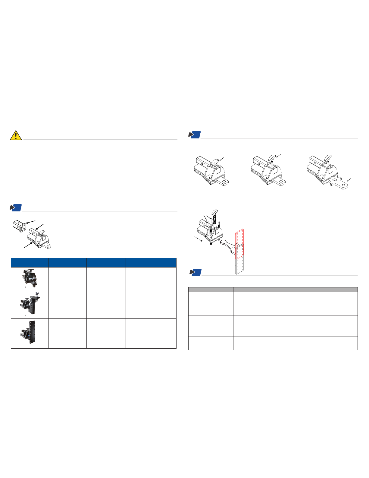
Operation
To connect to your trailer
1. Back up tow vehicle to get close to the trailer.
2. Lift up handle (ref A) to unlock.
(A)
3. Extend and swivel the probe (ref B) to position under the trailer coupler.
4. Connect and lock the trailer coupler, safety chains and electrical cords.
5. Lock the TeleSwivel® into place by either backing into the chocked trailer or pulling slowly forward to align the tow vehicle
and trailer, and applying your tow vehicle’s brakes. The trailer will continue forward and lock in place. Ensure that the
TeleSwivel® locking pin is in place before towing.
Locked
position
Unlocked
position
(B)
Extended
position
1. Insert adapter arm (ref A) into your 2” receiver (ref B).
2. Insert a hitch pin rated at least 10,000 pounds GTW through the receiver hole to
secure your adapter (a locking hitch pin is recommended).
3. For the TeleSwivel® 210 attach any standard hitch ball rated for 10,000 pounds
GTW. For the TeleSwivel® 210 AP, or 210 DH, attach your desired accessory
in accordance with specific weight requirements, not to exceed GTW rating per
probe type (see table below).
Products Max Ratings Rise / Drop Product
Compatibility
TeleSwivel® 210
10,000 lbs gross trailer
weight
1,000 lbs tongue weight
A standard hitch ball is
equivalent to a 4” drop.
Any 1
7/8
”, 2”, or 2
5/16
” hitch ball
with 1” diameter shank.
TeleSwivel® 210 DH
10,000 lbs gross trailer
weight
1,000 lbs tongue weight
Adjustable over 11”
range.
Probe reverses to allow:
Rise: 4”
Drop: 7”
Ball mount can accommodate
any 1
7/8
”, 2”, or 2
5/16
” hitch
ball with 1” diameter shank.
Accomodates most weight
distribution heads.
TeleSwivel® 210 AP
10,000 lbs gross trailer
weight*
1,000 lbs tongue weight
*Note: Pintle Ball accessories
in the lowest drop position
reduces rating to 8,000 lbs
GTW
Adjustable over 11”
range.
Probe reverses to allow:
Rise: 3”
Drop: 8”
Plate will accommodate most
bolt-on combination hitch
accessories, with a hole pattern
of 3
3/8
“ across and 1
3/4
” down.
(A)
To increase the drop on your hitch
1. Remove the two clips (ref A) to release the two stop pins (ref B).
(Note: The unit may need to be pulled out of the receiver in order to
remove the stop pins on some vehicles.)
2. Pull handle (ref C) to unlock and pull the probe (ref D) completely out
and reinsert with the mounting plate (ref H) in the reversed position.
WARNING: Probe is heavy.
3. Replace the two stop pins and secure with the clips.
(A)
(C)
(B)
(D)
 Loading...