

Telestream Wirecast Gear 210, Wirecast Gear 110, Wirecast Gear 220, Wirecast Gear 230 User Manual

User Guide
Wirecast Gear User Guide | 229961
September 2017
Wirecast Gear User Guide 1.0
The latest version of the Wirecast Gear User Guide is available at:
http://www.telestream.net/pdfs/user-guides/Wirecast-Gear-User-Guide.pdf


Preface 7
Introduction to
WC Gear
9
3
Contents
Introduction 9
Overview 9
Wirecast Gear Models 9
Features 10
Unpacking Wirecast Gear 10
Registering Wirecast Gear 11
Specifications 11
Operating System Specifications 11
Software Specifications 11
Hardware Specifications 12
WC Gear
Panels
Introduction 13
Front Panel 14
Rear Panel 15
Rear Panel Differences 16
13
Installation of
WC Gear
19
Introduction 19
Physical Mounting 19
Wireless Connections 19

4
Contents
Using
WC Gear
Introduction 23
Getting Started 23
First Time Boot 23
Configuring the I/O Ports 26
Introduction 26
Setup 26
Reference Input 30
23
Troubleshooting and
Updating WC Gear
Introduction 31
General 31
Drive Initialization 32
Windows Update Issues 33
31
Support for
WC Gear
Introduction 35
Obtaining Support | Information | Assistance 35
Return Merchandise Authorization (RMA) Procedure 37
Support and RMA Process 37
35
Regulatory Compliance Statements 39
Introduction 39
Regulatory Compliance Statements for the Wirecast Gear models 110, 210, 220 and
39
230
Local Restrictions on 802.11a, 802.11b, 802.11g and 802.11n Radio Usage Caution
39
Federal Communications Commission (FCC) Compliance Notices 40
Class B Interference Statement 40
FCC Caution 40
RF Radiation Exposure & Hazard Statement 41
Non-Modification Statement 41
Unlicensed National Information Infrastructure (U-NII) Bands Operation Statement
41
Dynamic Frequency Selection (DFS) 41
Canadian ICES Statements 42
RF Radiation Exposure & Hazard Statement 42
Exposition aux radiations RF & Mention de danger 42
Deployment Statement 43
Déclaration de déploiement 43
Operation in the Frequency Bands 5470-5725 MHz and 5725-5850 MHz 43

Contents
Fonctionnement dans les bandes de fréquence 5470-5725 MHz et 5725-5850 MHz
43
European Union and European Fair Trade Association Regulatory Compliance 43
Declaration of Conformity 44
Warning! 44
Achtung! 44
Attention! 45
National Restrictions 45
Indoor Operation 45
Antenna 45
Power Level Control 45
Operating Frequency 45
Warning and Caution Messages 45
Before operation please read the following: 46
5

6
Contents

Copyrights and Trademark Notices
Copyright 2017 Telestream, LLC. All rights reserved. No part of this publication may be
reproduced, transmitted, transcribed, altered, or translated into any languages without
written permission of Telestream, LLC. Information and specifications in this document
are subject to change without notice and do not represent a commitment on the part
of Telestream.
7
Preface
Limited Warranty and Disclaimers
Telestream, LLC (the Company) warrants to the original registered end user that the
product will perform as stated below for a period of one (1) year from the date of
shipment from factory, unless the customer has purchased additional warranty periods.
The Product hardware components, including equipment supplied but not
manufactured by the Company but NOT including any third party equipment that has
been substituted by the Distributor for such equipment (the "Hardware"), will be free
from defects in materials and workmanship under normal operating conditions and
use.
Warranty Remedies
Your sole remedies under this limited warranty are as follows:
The Company will either repair or replace (at its option) any defective Hardware
component or part with new or fully functioning hardware components.
Components may not be necessarily the same, but will be of equivalent operation and
quality.
Software Updates
Except as may be provided in a separate agreement between Telestream and You, if
any, Telestream is under no obligation to maintain or support the Software and

8
Preface
Telestream has no obligation to furnish you with any further assistance, technical
support, documentation, software, update, upgrades, or information of any nature or
kind.
Note: Wirecast Gear includes 90 days of complimentary support on both hardware
and software.
Restrictions and Conditions of Limited Warranty
This Limited Warranty will be void and of no force and effect if (i) Product Hardware or
Software Media, or any part thereof, is damaged due to abuse, misuse, alteration,
neglect, or shipping, or as a result of service or modification by a party other than the
Company, or (ii) Software is modified without the written consent of the Company.
Limitations of Warranties
THE EXPRESS WARRANTIES SET FORTH IN THIS AGREEMENT ARE IN LIEU OF ALL OTHER
WARRANTIES, EXPRESS OR IMPLIED, INCLUDING, WITHOUT LIMITATION, ANY
WARRANTIES OF MERCHANTABILITY OR FITNESS FOR A PARTICULAR PURPOSE. No oral
or written information or advice given by the Company, its distributors, dealers or
agents, shall increase the scope of this Limited Warranty or create any new warranties.
Damages
Geographical Limitation of Warranty—This limited warranty is valid only within the
country in which the Product is purchased/licensed.
Limitations on Remedies—YOUR EXCLUSIVE REMEDIES, AND THE ENTIRE LIABILITY OF
TELESTREAM, LLC WITH RESPECT TO THE PRODUCT, SHALL BE AS STATED IN THIS
LIMITED WARRANTY. Your sole and exclusive remedy for any and all breaches of any
Limited Warranty by the Company shall be the recovery of reasonable damages which,
in the aggregate, shall not exceed the total amount of the combined license fee and
purchase price paid by you for the Product.
TELESTREAM, LLC SHALL NOT BE LIABLE TO YOU FOR ANY DAMAGES, INCLUDING ANY
LOST PROFITS, LOST SAVINGS, OR OTHER INCIDENTAL OR CONSEQUENTIAL DAMAGES
ARISING OUT OF YOUR USE OR INABILITY TO USE THE PRODUCT, OR THE BREACH OF
ANY EXPRESS OR IMPLIED WARRANTY, EVEN IF THE COMPANY HAS BEEN ADVISED OF
THE POSSIBILITY OF THOSE DAMAGES, OR ANY REMEDY PROVIDED FAILS OF ITS
ESSENTIAL PURPOSE.
Further information regarding this limited warranty may be obtained by writing:
Telestream, LLC
848 Gold Flat Road
Nevada City, CA 95959 USA
You can call Telestream, LLC via telephone at (530) 470-1300.

Introduction
This section presents an overview of Wirecast Gear models, features, etc.), and how to
unpack, setup, and register it. Specifications are also provided.
9
Introduction to
WC Gear
Top ics
Overview
Unpacking Wirecast Gear
Registering Wirecast Gear
Specifications
Overview
Wirecast Gear is an integrated solution for live production, streaming, video ingest and
more. It is designed to provide an easy to operate experience and is based on a
standard Windows 10 personal computer.
Note: Consult the Wirecast User Guide included with Wirecast Gear. You can download
this user guide from the Telestream web site at:
http://www.telestream.net/telestream-support/wire-cast/help.htm
Wirecast Gear Models
Wirecast Gear is available in these models:
• Wirecast Gear 110 - 4 Channel HDMI 250GB SSD Video Storage
• Wirecast Gear 210 - 4 Channel SDI 500GB SSD Video Storage
• Wirecast Gear 220 - 4 Channel SDI 2TB SSD Video Storage
• Wirecast Gear 230 - 4 Channel SDI 2TB SSD Video Storage
(with input and output capability)

10
Introduction to WC Gear
Unpacking Wirecast Gear
Features
• Windows 10 Pro 64-bit OS
• 4 Port (SDI or HDMI) high quality video ingest
• Wirecast Pro
• Convertible mini case with rubber feet for table-top use and included rackmount
brackets for installing in approved flight/transport cases or in-place rack configura-
tions. Unit has no platter-based hard drives, making it ideal for transport
• Extensive source inputs including professional video connectors
• Multiple LAN/Wifi ports, USB 3.0 (including Type C) and more
• USB 3.0 (including Type C) and more
• Up to 4 channel ISO recording with full Instant Replay capability
• Three digital video output ports for multiple display configuration and on-site large
format display outputs (IMAG) with lowest latency including support for up to
UHD/4K resolutions
• Live source processing including scaling, rotation, color correction and keying.
• Compatible with industry standard applications such as Adobe CC, Microsoft Office
and most standard Windows 10 compatible applications/utilities
• System Refresh allows quick recovery to factory settings in case of system corrup-
tion or failure. All Telestream loaded applications will be recovered (user applica-
tions must be reinstalled)
Unpacking Wirecast Gear
Unpack the contents of the shipping container; identify each component and
determine that it has arrived in satisfactory condition.
If there is shipping damage to the box, note it on your shipping documents and contact
the carrier immediately. If the computer or box contents are damaged in any way, you
should file a claim with the carrier and notify Telestream immediately.
Note: Save the shipping container and packaging materials and store them in a safe
place. If you require service—or move your Wirecast Gear — the packaging materials
should be used for safe shipment.
Shipping Container Contents
Each Wirecast Gear box contains the following:
• Wirecast Gear computer
• Logitech Wireless Keyboard/Mouse combo
• Power cord

• Accessory box - feet, screws, rack ears, rack ears, WiFi antenna
• Plastic bag
Registering Wirecast Gear
Registering your Wirecast Gear system is a requirement to gain access to your licensed
copies of Telestream-bundled software. It also ensures the following:
Safety—so you'll be kept informed of product feature updates and improvements
Service—to receive the excellent Telestream warranty service and technical support
Security—in the event of loss, theft or catastrophic events, your registration may serve
as proof of purchase for your insurance carrier
Registration is quick, easy, and important—follow these steps:
1. Go to the Wirecast Gear registration web page: http://www.telestream.net/
telestream-support/Wirecast-Gear/register.htm
Introduction to WC Gear
Registering Wirecast Gear
11
2. Complete the Wirecast Gear registration.
3. Click Submit to complete registration.
Specifications
The following topics summarize Wirecast Gear specifications.
CAUTION: Wirecast Gear is a sealed device, with no user-serviceable parts or useraccessible expansion slots. You should never open or attempt to upgrade or alter the
computer. Doing so exposes you to electrical hazard, may damage the unit, and may
invalidate your warranty. If you have hardware or software problems with your
Wirecast Gear, follow the steps in the Return Merchandise Authorization (RMA)
Procedure later in this guide to obtain service.
Operating System Specifications
Wirecast Gear is pre-installed with Windows 10 OS. Please see the Microsoft web site for
specifications.
Software Specifications
• Tele st rea m Wirecast Pro application software
• Tele st rea m Switch application software

12
Introduction to WC Gear
Specifications
• NewBlueFX Titler Live Standard, Advance NDI, or Ultimate
– Model 110 uses NewBlueFX Titler Present
– Model 210 uses NewBlueFX Titler Sport
– Model 220 & 230 uses NewBlueFX Titler Complete
Hardware Specifications
• Intel Core i7-6700 8M Skylake Quad-Core 3.4 GHz
• Intel HD Graphics 530
• Memory - DDR4 Dual Channel Memory
• System Drive - M.2 SATA System Drive
• Storage Drive(s) - High speed SATA 6Gb/s SSD (single or dual, depending on model)
• Video Ingest - 4-channel professional camera inputs with HDMI or SDI models available
• Motherboard features
– Intel® USB 3.0 with USB Type-C™
– 802.11ac 867 Mbps dual band wireless (including antenna) + Bluetooth®
– 115dB SNR HD Audio with Built-in Rear Audio Amplifier
– Dual Intel® GbE LAN RJ45
– PS/2 Keyboard/Mouse Port
– USB 3.0 Ports - 4 rear/2 front
– Display outputs - DVI-D, dual HDMI
• Wireless Keyboard and Mouse combo
• Power Supply: AC input, auto-sensing, suitable for most countries worldwide
– Input Range: 90 ~ 264Vac (RMS), Full Range Input
– Frequency: 47 ~ 63Hz
– Input Current: Max 6A (RMS) @ 115Vac, 3A (RMS) @ 230Va
• Dimensions: 16.55 x 9.85 x 2.25 inches, 1.3U rackmount height (rear brackets avail-
able for transport cases).
Note: Wirecast Gear has no user-serviceable parts. Any repair or additional PCI card
installation must be performed by Telestream or an authorized Telestream service
technician.

Introduction
The following topics describe the Wirecast Gear front and rear panels.
13
WC Gear
Panels
Top ics
Note: Please do not make any connections just yet. First, read the panel and connector
descriptions and then proceed to the Installation of WC Gear topic for steps to install
and connect to the unit.
Wirecast Gear is available in HDMI and SDI configurations. Both configurations share
the same front panel features, but each configuration has a unique rear panel. Wirecast
Gear 100 series models include 4-channel HDMI professional inputs, while Wirecast
Gear 200 series models are SDI-based and use BNC connectors.
Front Panel
Rear Panel
Rear Panel Differences
14
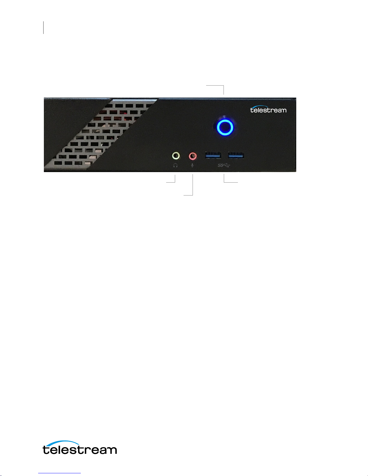
4. USB 3.0
2. Line Out (green)
3. Mic In (Pink)
1. Power Button
WC Gear Panels
Front Panel
Front Panel
Wirecast Gear has the following connectors on the front panel.
1. Power Button This button turns the power on and off. When on, a blue light is
displayed.
2. Line Out (Green) Use this output for headphones or a speaker system. You can also
connect front speakers in a 4/5.1/7.1-channel audio configuration.
3. Mic In (Pink) Use this input for Microphones. Many live producers choose to use a
USB-based external audio configuration with either a simple A/D device with
professional connectors or a full audio mixer panel for tactile control of audio
levels. External devices must be USB 2.1 compatible. Contact the reseller who sold
you your Wirecast Gear unit for specific brand and model information.
4. USB 3.0 Port The USB 3.0 port supports the USB 3.0 specification and is compatible
to the USB 2.0/1.1 specification. Use this port for USB devices.

Rear Panel
11. USB Type-C™
Port
12. HDMI
Output Ports
6. Line In
4. Center/Subwoofer
Speaker Out
1. PS/2 Keyboard/
Mouse Port
3. RJ-45
LAN Ports
9. Optical S/PDIF Out
5. Rear
Speaker Out
7. Line Out
8. Mic In
2. SMA Antenna
Connectors
10. USB 3.0/2.0 Ports
13. DVI-
D Port
The Rear Panel connectors have the following functionality.
WC Gear Panels
Rear Panel
15
1. PS/2 Keyboard/Mouse Port Use this port to connect a PS/2 mouse or keyboard.
2. SMA Antenna Connectors (2T2R) Use this connector to connect an antenna.
Tighten the antenna cables to the antenna connectors and then move the antenna
to a place where the signal is good.
3. RJ-45 LAN Port The Gigabit Ethernet LAN port provides Internet connection at up
to 1 Gbps data rate. The following describes the states of the LAN port LEDs.
4. Center/Subwoofer Speaker Out (Orange) Use this audio jack to connect center/
subwoofer speakers in a 5.1/7.1-channel audio configuration.
5. Rear Speaker Out (Black) This jack can be used to connect speakers in a 4/5.1/7.1channel audio configuration.
6. Line In (Blue) Line in jack. Use this for external audio devices other than
microphones.
7. Line Out (Green) Line out jack. This jack supports audio amplifying function. For
better sound quality, it is recommended that you connect your headphone/
speaker to this jack (actual effects may vary by the device being used). Use this
audio jack for a headphone or 2-channel speaker. This jack can be used to connect
front speakers in a 4/5.1/7.1-channel audio configuration.
8. Mic In (Pink) The Mic in jack. Microphones must be connected to this jack.

16
HDMI Input Connectors
Model 110 Rear Panel with HDMI
1 2 3 4
WC Gear Panels
Rear Panel Differences
CAUTION: When removing any mic cable, pull it straight out from the connector to
prevent causing a short inside the cable connector.
9. Optical S/PDIF Out Connector This connector provides digital audio out to an
external audio system that supports digital optical audio. Before using this feature,
ensure that your audio system provides an optical digital audio in connector.
10. USB 3.0/2.0 Port The USB 3.0 port supports the USB 3.0 specification and is
compatible to the USB 2.0/1.1 specification. Use this port for USB devices.
11. USB Type-C™ Port The USB 3.0 port supports the USB 3.0 specification and is
compatible to the USB 2.0/1.1 specification. Use this port for USB devices.
12. HDMI Output Ports The HDMI port is HDCP compliant and supports Dolby® True
HD and dts® HD Master Audio formats. It also supports up to 192KHz/24bit 8channel LPCM audio output. You can use this port to connect your HDMIsupported monitor. The maximum supported resolution is 4096x2160@24 Hz, but
the actual resolutions supported are dependent on the monitor being used.
13. DVI-D Port The DVI-D port conforms to the DVI-D specification and supports a
maximum resolution of 1920x1200@60 Hz (the actual resolutions supported
depend on the monitor being used). Connect a monitor that supports DVI-D
connection to this port.
Note: The DVI-D port does not support D-Sub connection by adapter.
Rear Panel Differences
Depending on the Wirecast Gear model, four HDMI (model 110) or SD/HD/3G-SDI
(models 210, 220, 230) video inputs are provided on the right side of the rear panel. The
location and numbering of inputs are shown below.

WC Gear Panels
SD/HD/3G-SDI BNC Input Connectors
Model 210/220 Rear Panel with SDI BNC
SDI 4 SDI 2
SDI 3 SDI 1
SD/HD/3G-SDI BNC Input Connectors
Model 230 Rear Panel with SDI BNC and Ref Input
SDI 1 SDI 2
REF SDI 3 SDI 4
Rear Panel Differences
17
Note: The default SDI number assignment on the model 230 are out of order and
differ from the numbering of the model 220.
Connect the inputs to your video sources, such as cameras, DVD players, computers,
editors, graphics cards, and other devices that produce a video output that you want to
use as an input for live production.

18
WC Gear Panels
Rear Panel Differences

Introduction
This section shows you how to install WC Gear. This includes physical mounting and
wireless connections.
19
Installation of
WC Gear
Note: Before installing WC Gear, read through the section on WC Gear Panels.
Top ics
Physical Mounting
Wireless Connections
Physical Mounting
Wirecast Gear comes configured for table-top use with the included feet pre-attached.
The unique size and shape of Wirecast Gear is designed to occupy a minimum of space
while making connectors and cables easily accessible.
Also included with all Gear systems are two rack-mount "ears" and screws that allow the
system to fit into a standard 19-inch rack and take up 1.3 RU (Rack Units). This
configuration is useful for in-place racks and mobile flypacks where convenient and
safe transport of your live production system is required.
Note: The rack-mount configuration will require removal of rubber feet remove the
vent warning label on top of the unit, if desired. It is there to remind you to never block
the top of chassis air vents.
Wireless Connections
To make connections to your Wirecast Gear system, refer to WC Gear Panels for
connector functions and locations, and then follow these steps.

20
Installation of WC Gear
Wireless Connections
Note: The Wirecast Gear system is configured to work with up to three displays.
1. If you plan to use Wifi, connect the antenna to the two jacks and position the
antenna as desired.
2. If available, plug a network cable into one of the available RJ45 Ethernet jacks.
Note: After it is powered on, Wirecast Gear will attempt to automatically connect to
your installed network configuration (via LAN). If your network requires authentication
or specific configuration, please check with your network administrator to determine
computer and network setting requirements.
3. Plug HDMI or SDI cables into the 4 video input connectors on the right rear panel.
4. Plug a standard computer monitor into either the HDMI or DVI monitor output
ports on the back of the unit.
Note: Every Wirecast Gear unit has two HDMI outputs and one DVI-D output. These
are standard display outputs that are used for connecting computer monitors. If you
have more than one monitor installed, Wirecast will allow you to send a full screen
output of your program to the second display as a program monitor. These are also the
ports to be used for in-venue, presentation displays (also known as IMAG) as they
provide for the lowest latency output.
5. Make audio input and output connections to Line In, Mic In, Speaker Out, and
Optical S/PDIF Out.
6. Remove the USB dongles from the bottom of the wireless mouse.
Note: The mouse dongle communicates to both the mouse and the keyboard.

Installation of WC Gear
Front USB ports
Rear USB ports
Wireless Connections
7. Insert the USB dongle into a USB port on the front or back of the WC Gear box.
21
8. Turn the keyboard and mouse on, using the power switch on each.
9. After all connections have been made, plug in the attached power cord to provide
power to the unit. For input power requirements, see Specifications.
10. Turn on Wirecast Gear unit by pushing the power button on the front. The button
will light, and the unit will begin to boot up.

22
Installation of WC Gear
Wireless Connections

Introduction
This section shows you how to get started using WC Gear and what to do when you
boot up for the first time.
23
Using
WC Gear
Top ics
Getting Started
First Time Boot
Configuring the I/O Ports
Getting Started
To get started using Wirecast Gear, follow these steps:
1. If you aren’t familiar with Wirecast, read the Wirecast User Guide. You can download
it from the Telestram web site at:
http://www.telestream.net/telestream-support/wire-cast/help.htm
2. Personalize Windows as explained in the First Time Boot topic below.
3. Create individual Windows user accounts on the Wirecast Gear machine, if desired.
You are now ready to start using Wirecast to stream your live presentations.
First Time Boot
Every Wirecast Gear unit includes a pre-activated copy of Windows 10 Pro 64-bit. There
is no need to enter a serial number or product key.
When you first power up Wirecast Gear, you are prompted to configure Windows for
your locale and personal preferences. The following screen shots explain this process:

24
Using WC Gear
First Time Boot
1. Select Location, Language and Time.
2. When the Microsoft License Acceptance displays, read and click Accept.

3. Unless you have a specific requirement, click Use Express settings.
Using WC Gear
First Time Boot
25
4. When the Create Account window displays, enter your user name and password
and click Next.
After a brief period of configuration, your Wirecast Gear will boot for the first time into
Windows 10.

26
Select
Blackmagic
Using WC Gear
Configuring the I/O Ports
Configuring the I/O Ports
Note: This section applies only to Wirecast Gear model 230.
Introduction
This section demonstrates how to setup the individual SDI connectors on the
Blackmagic DeckLink Duo card. This enables the card to capture from all four inputs
simultaneously in Wirecast.
Setup
To configure the SDI connectors on the Blackmagic card, follow these steps:
1. Press the Windows key and the “S” key together, to open the search window. Enter
“Desktop Video” to display the Blackmagic setup icon, and then press the Enter key
to select it.

Using WC Gear
Click
configure
button
Logical
input (1)
Click
Connectors
tab
Configuring the I/O Ports
2. When the setup window displays, logical input (1) is selected. Click on the configure
button in the middle of the window to setup this logical input.
27
3. When logical input (1) setup window displays, click the Connectors tab.

28
Select
SDI 1
Click
Save
Click right
arrow
Logical
input (2)
Click
configure
button
Using WC Gear
Configuring the I/O Ports
4. When the connector tab window displays, select connector SDI 1 from the drop-
down menu, then click Save.
5. When the setup window displays, click the right arrow to select the setup page for
the DeckLink Duo (2) input. Then click the Configure button in the center of the
page to open the properties for logical input (2).

6. Click the Connectors tab.
Click
Connectors
tab
Select
SDI
Click
Save
Logical input
numbers
7. select connector SDI 3 from the drop-down menu, then click Save.
Using WC Gear
Configuring the I/O Ports
29
8. Check logical inputs (3) and (4) to make sure they are assigned to SDI 2 and SDI 3,
and not to a dual connector setting like “SDI 3 & SDI 4”.
NOTE: Even though you are configuring logical input (2), you are assigning physical
connector SDI 3 to it. The logical input numbers are displayed in parentheses, as “(2)”,
etc., in the Blackmagic setup window:

30
Logical input
numbers
Adjust slider
Using WC Gear
Configuring the I/O Ports
But they are also displayed as selections in Capture Devices of the Shot Selection menu:
The physical SDI connectors are identified by “SDI 1”, etc. (See “Model 230 Rear Panel”
on Rear Panel Differences for details).
Reference Input
The Reference Adjustment enables you to set the timing of the video outputs relative
to the reference input signal. This is often used when the video output needs to be
synced up with other video outputs. The reference adjustment can be accurately timed
down to the sample level.
To adjust the reference input, move the offset slider to time the video output relative to
the reference input. The Reference input slider is located at the bottom of the Video
Output tab at the in the Connector Setup window.
This adjustment makes it possible to switch between devices on a downstream router
(or production switcher), by eliminating any “glitching” when switching is performed.

Introduction
This section shows you how to troubleshoot Wirecast Gear and how to get updates
31
Troubleshooting and
Updating WC Gear
Top ics
General
General
Drive Initialization
Windows Update Issues
If your Wirecast Gear computer does not operate as expected, the following tips may
provide assistance.
CAUTION: Wirecast Gear is a sealed device, with no serviceable parts and no internal
peripheral bays. Please do not open the chassis to try to diagnose the hardware failure
yourself, unless permitted to do so. This will void your warranty with Telestream and
our manufacturer.
• Close any programs (except Wirecast) that you are not using because other pro-
grams can take up too much memory.
• Save any work in progress, then close and reopen Wirecast.
• Restart the computer. Random problems can sometimes be resolved by a restart.
Be sure to save your work before you shut the computer down.
If you cannot resolve an issue yourself, see Obtaining Support | Information | Assistance.

32
Troubleshooting and Updating WC Gear
Drive Initialization
Drive Initialization
If you have received a Wirecast Gear unit and it is missing the secondary hard drive in
Windows, but you can see it in Disk Management (right click on the start button,
choose disk management), the drive is just in need of initialization.
To do this, follow these steps:
1. Open Disk Management, right click the partition you need to format (partition D),
then select Format.
2. In the pop-up window, set file system and cluster size, then click OK.

Your drive is now accessible in Wirecast and Windows.
Question Mark
Windows Update Issues
If you receive an question mark (?) with a yellow exclamation mark next to the capture
devices, you may be experiencing a Microsoft Windows update issue.
Microsoft issued a statement updates will cause Windows computers (including
Wirecast Gear) to lose their drivers to capture devices.The fastest way to resolve this is
to download the latest drivers from the Magewell website:
http://www.magewell.com/downloads.
Troubleshooting and Updating WC Gear
Windows Update Issues
33
Below is a link to an article that further explains the Microsoft Windows update issue:
http://www.howtogeek.com/243581/windows-10-may-delete-your-programswithout-asking/.

34
Troubleshooting and Updating WC Gear
Windows Update Issues

Introduction
This section shows you how to obtain customer support for WC Gear and how to make
returns.
35
Support for
WC Gear
Top ics
Obtaining Support | Information | Assistance
Return Merchandise Authorization (RMA) Procedure
Obtaining Support | Information | Assistance
Support options for your Wirecast Gear are listed and briefly described below. Provide
your organization name, and contact information, and the serial number of the affected
unit. If the problem cannot be resolved remotely, request an RMA (Return Material
Authorization).

36
Support for WC Gear
Obtaining Support | Information | Assistance
Support Resources Details and Contact Information
Reseller Support If you purchased your Wirecast Gear from a reseller and
did not also purchase GearCare Premium Support, please
contact your reseller for product support.
Telestream WC Gear
Support
GearCare Premium
Support
Wirecast Information,
Assistance, FAQs,
Forums, & Upgrades
Telestream, LLC General
Information
Customers who bought Wirecast Gear directly from
Telestream may request support as outlined below.
• Support Web Site: http://www.telestream.net/
telestream-support/Wirecast-Gear/support.htm
• Support Email: desktopsupport@telestream.net
Terms and times of support services vary, per the terms of
your current service contract with Telestream.
Customers who bought GearCare Premium Support may
request support as outlined below. Includes a 3-year
extended warranty and overnight replacement.
• US Support Phone: 1-844-550-5208
• International Support Phone: 1-530-470-2029
• Support Email: desktopsupport@telestream.net
See also the web sites above and below.
• Wirecast Web Site: http://www.telestream.net/
telestream-support/wire-cast/support.htm
• Web Site: www.telestream.net
• Sales and Marketing Email: info@telestream.net
Telestream Technical
Writers
Physical location and mailing address:
Telestream, LLC
848 Gold Flat Road
Nevada City, CA USA 95959
• Email: techwriter@telestream.net
Comments, corrections, or suggestions about this guide
and other Telestream guides are encouraged.

Return Merchandise Authorization (RMA) Procedure
Return Merchandise Authorization (RMA)
Procedure
If your Wirecast Gear needs service of any kind, see Obtaining Support | Information |
Assistance on the previous page for contact information.
If you are instructed by Telestream Support to return your Wirecast Gear, follow the
procedure below. Please do not return a Wirecast Gear unit unless you receive an RMA
number from Telestream first.
Before returning your Wirecast Gear, Telestream recommends that you back up the
entire contents of all computer drives.
Support and RMA Process
1. Contact the reseller where your hardware was purchased for service. If you
purchased directly from Telestream or your unit is covered by Premium Support,
contact Telestream.
Support for WC Gear
37
2. Telestream Support opens a case for you.
3. Telestream Support follows an established drill-down to categorize the problem,
and determine a resolution path.
4. If the problem is beyond our initial level of Support, our representatives will access
and diagnose your device remotely. You will need to grant us Internet access to
your device.
5. Upon a failed hardware diagnosis, our representative escalates the case to an RMA
and gives you instructions for shipping the unit to our manufacturing partner for
repair.
6. The RMA process triggers a case with our manufacturing partner.
a. If you have Premium Support, the manufacturing partner gathers your shipping
and contact information and sends you an overnight replacement. The
manufacturer will also give you instructions and an RMA for returning the failed
unit.
b. If you do not have Premium Support, the manufacturing partner gives you
instructions and an RMA for returning the failed unit and gathers your return
shipping information. You are requested to ship the unit to our manufacturing
partner for repair and return to you.
7. Upon case resolution, Telestream Support reviews and closes the case and sends
you a satisfaction questionnaire.
8. We appreciate your business and ask you to return the questionnaire promptly so
that we can continue to improve the quality of our product support to you and our
other customers.

38
Support for WC Gear
Return Merchandise Authorization (RMA) Procedure

Introduction
This section presents the Regulatory Compliance Statements for the Wirecast Gear
models 110, 210, 220 and 230. It also includes European Union and European Fair Trade
Association Regulatory Compliance, along with Warning and Caution Messages
39
Regulatory
Compliance
Statements
Top ics
Regulatory Compliance Statements for the Wirecast Gear models 110, 210, 220 and 230
Federal Communications Commission (FCC) Compliance Notices
Canadian ICES Statements
European Union and European Fair Trade Association Regulatory Compliance
Warning and Caution Messages
Regulatory Compliance Statements for the Wirecast
Gear models 110, 210, 220 and 230
Local Restrictions on 802.11a, 802.11b, 802.11g and
802.11n Radio Usage Caution
Due to the fact that the frequencies used by 802.11a, 802.11b, 802.11g and 802.11n
wireless LAN devices may not yet be harmonized in all countries, 802.11a, 802.11b,
802.11g and 802.11n products are designed for use only in specific countries, and are
not allowed to be operated in countries other than those of designated use. As a user of
these products, you are responsible for ensuring that the products are used only in the
countries for which they were intended and for verifying that they are configured with
the correct selection of frequency and channel for the country of use. Any deviation
from the permissible power and frequency settings for the country of use is an
infringement of national law and may be punished as such.
To determine whether you are allowed to use your wireless network device in a specific
country, please check to see if the radio type number that is printed on the

40
Regulatory Compliance Statements
Federal Communications Commission (FCC) Compliance Notices
identification label of your device is listed in the manufacturer's OEM Regulatory
Guidance document at URL http://www.telestream.net/pdfs/regulatory/
Gear-regulatory-guidance.pdf, or contact Telestream directly.
Federal Communications Commission (FCC)
Compliance Notices
This section includes the following FCC statements for the Wirecast Gear models 110,
210, 220 and 230:
• These models contain FCC ID: PD98260NG
• Class B Interference Statement
• RF Radiation Exposure & Hazard Warning
• Non-Modification Statement
• Unlicensed National Information Infrastructure Bands Operation Statement
Class B Interference Statement
This equipment has been tested and found to comply with the limits for a Class B digital
device, pursuant to Part 15 of the FCC Rules. These limits are designed to provide
reasonable protection against harmful interference in a residential installation. This
equipment generates, uses, and can radiate radio frequency energy and, if not installed
and used in accordance with the instructions, may cause harmful interference to radio
communications. However, there is no guarantee that interference will not occur in a
particular installation. If this equipment does cause harmful interference to radio or
television reception, which can be determined by turning the equipment off and on,
the user is encouraged to try to correct the interference by one or more of the following
measures:
• Reorient or relocate the receiving antenna.
• Increase the separation between the equipment and receiver.
• Connect the equipment into an outlet on a circuit different from that to which the
receiver is connected.
• Consult the dealer or an experienced radio/TV technician for help.
FCC Caution
This device complies with Part 15 of the FCC Rules. Operation is subject to the following
two conditions: (1) This device may not cause harmful interference, and (2) this device
must accept any interference received, including interference that may cause
undesired operation.

Federal Communications Commission (FCC) Compliance Notices
RF Radiation Exposure & Hazard Statement
To ensure compliance with FCC RF exposure requirements, this device must be installed
in a location such that the antenna of the device will be greater than 20 cm (7.8 in.)
from all persons. Using higher gain antennas and types of antennas not covered under
the FCC certification of this product is not allowed. Installers of the radio and end users
of the product must adhere to the installation instructions provided in this manual. This
transmitter must not be co-located or operated in conjunction with any other antenna
or transmitter.
Non-Modification Statement
Use only the supplied antenna. Unauthorized antennas, modifications, or attachments
could damage the Wirecast Gear models 110, 210, 220 and 230 and violate FCC
regulations. Any changes or modifications not expressly approved by the party
responsible for compliance could void the user's authority to operate this equipment.
Please contact Telestream for a list of approved 2.4 GHz and 5.0 GHz antennas.
Regulatory Compliance Statements
41
Unlicensed National Information Infrastructure (U-NII)
Bands Operation Statement
Within the 5.25-5.35 GHz band, U-NII devices will be restricted to indoor operations to
reduce any potential for harmful interference to co-channel MSS operations.
The U-NII devices shall accept any interference from legal communications and shall
not interfere with the legal communications. If interference is caused, the user must
stop operating the device immediately and cannot resume operation until the harmful
interference is clear.
Manufacturers of U-NII devices are responsible for ensuring frequency stability such
that an emission is maintained within the band of operation under all conditions of
normal operation as specified in this user manual.
Dynamic Frequency Selection (DFS)
U-NII devices operating in the 5.25-5.35 GHz and 5.47-5.725 GHz bands shall employ a
DFS radar detection mechanism to detect the presence of radar systems and to avoid
co-channel operation with radar systems in order to reduce the likelihood of
interference to radar.
The modification of wireless broadband and other transceiver devices to operate on
unauthorized frequencies or the disabling of DFS capabilities is a violation of FCC rules
and may result in unlawful interference to radio communications services critical to
public safety

42
Regulatory Compliance Statements
Canadian ICES Statements
Canadian ICES Statements
Contains IC: 1000M-8260NG
This device complies with ICES-003 and RSS-247 of Industry Canada.
Operation is subject to the following two conditions:
1. This device may not cause interference, and
2. This device must accept any interference, including interference that may cause
undesired operation of the device.
Ce dispositif est conforme aux normes NMB003 et CNR-247 d'Industrie Canada.
1. L'utilisation de ce dispositif est autorisée seulement aux conditions suivantes :
2. il ne doit pas produire de brouillage et l'utilisateur du dispositif doit être prêt à
accepter tout brouillage radioélectrique reçu, même si ce brouillage est susceptible
de compromettre le fonctionnement du dispositif.
To prevent radio interference to the licensed service (i.e. co-channel Mobile Satellite
systems) this device is intended to be operated indoors and away from windows to
provide maximum shielding. Equipment (or its transmit antenna) that is installed
outdoors is subject to licensing and not supported by Wirecast Gear 110, 210, 220 and
230 Models.
Pour éviter les interférences radio au service agréé (c.-à-d. Les systèmes par satellite
mobile co-canal), cet appareil est destiné à fonctionner à l'intérieur et à l'extérieur des
fenêtres pour assurer un blindage maximal. L'équipement (ou son antenne d'émission)
installé à l'extérieur est soumis à l'octroi de licences et n'est pas pris en charge par les
modèles Wirecast Gear 110, 210, 220 et 230.
RF Radiation Exposure & Hazard Statement
To ensure compliance with RSS-102 RF exposure requirements, this device must be
installed in a location such that the antenna of the device will be greater than 20 cm
(7.8 in.) away from all persons. Using higher gain antennas and types of antennas not
covered under the IC certification of this product is not allowed. Installers of the radio
and end users of the product must adhere to the installation instructions provided in
this manual. This transmitter must not be co-located or operated in conjunction with
any other antenna or transmitter.
Exposition aux radiations RF & Mention de danger
Pour assurer la conformité avec les exigences RSS-102 d'exposition aux RF (Radio
Fréquences), cet appareil doit être installé dans un endroit ou l'antenne de l'appareil
sera située à une distance de plus de 20 cm (7.8 po) de toutes personnes. L'utilisation
d'antennes à gain plus élevé et les types d'antennes qui ne sont pas couverts en vertu
de la certification IC de ce produit n'est pas autorisée. Les installateurs de la radio et les
utilisateurs du produit final doivent se conformer aux instructions d'installation

Regulatory Compliance Statements
European Union and European Fair Trade Association Regulatory Compliance
fournies dans ce manuel. Cet émetteur ne doit pas être co-implanté ou exploité en
conjonction avec toute autre antenne ou transmetteur.
Deployment Statement
This product is certified for indoor deployment only in the 5150 - 5250 MHz band. Do
not install or use this product outdoors in that frequency band in Canada.
Déclaration de déploiement
Ce produit est certifié pour le déploiement à l'intérieur tout en rencontrant les limites
de cette bande de fréquences: 5150 - 5250 MHz. Ne pas installer ou utiliser ce produit
à l'extérieur au Canada, si cette bande de fréquences ne peut ne peut être rencontrée.
Operation in the Frequency Bands 5470-5725 MHz and
5725-5850 MHz
43
Until further notice, devices subject to this section shall not be capable of transmitting
in the band from 5600-5650 MHz. This restriction is for the protection of Environment
Canada's weather radars operating in this band.
Users are advised that high-power radars are allocated as primary users (i.e. priority
users) of the bands 5250-5350 MHz and 5650-5850 MHz and that these radars could
cause interference and/or damage to LE-LAN devices.
Fonctionnement dans les bandes de fréquence 5470-5725
MHz et 5725-5850 MHz
Jusqu'à nouvel avis, les appareils soumis à cette section ne doivent pas être transmis
dans la bande de 5600-5650 MHz. Cette restriction concerne la protection des radars
météorologiques d'Environnement Canada opérant dans cette bande.
Les utilisateurs êtes avisés que les utilisateurs de radars de haute puissance sont
désignés utilisateurs principaux (c.-à-d., qu'ils ont la priorité) pour les bandes 52505350 MHz et 5650-5850 MHz et que ces radars pourraient causer du brouillage et/ou
des dommages aux dispositifs LAN-EL.
European Union and European Fair Trade
Association Regulatory Compliance
This equipment may be operated in the countries that comprise the member countries
of the European Union and the European Fair Trade Association. These countries, listed
below, are referred to as The European Community throughout this document:
AUSTRIA, BELGIUM, BULGARIA, CYPRUS, CZECH REPUBLIC, DENMARK, ESTONIA,
FINLAND, FRANCE, GERMANY, GREECE, HUNGARY, IRELAND, ITALY, LATVIA, LITHUANIA,

44
Regulatory Compliance Statements
European Union and European Fair Trade Association Regulatory Compliance
LUXEMBOURG, MALTA, NETHERLANDS, POLAND, PORTUGAL, ROMANIA, SLOVAKIA,
SLOVENIA, SPAIN, SWEDEN, UNITED KINGDOM, ICELAND, LICHTENSTEIN, NORWAY,
SWITZERLAND
Declaration of Conformity
Declaration of Conformity is marked by this symbol:
This indicates compliance with the Essential Requirements of the Radio Equipment
Directive (RED) of the European Union (2014/53/EU). This equipment meets the
following conformance standards:
Safety: EN 60950-1: 2006 + A11: 2009 + A1: 2010 + A12: 2011 + A2: 2014 (T-Mark
License), IEC 60950-1: 2005 (2nd Ed.) + Am 1: 2009 + Am 2: 2013 (CB Scheme Certificate)
EMC: EN 301 489-1 v2.1.1 (2017-02), EN 301 489-17 v3.1.1 (2016-11),
EN 55032: 2012, CISPR 32: 2015, EN 55024: 2010, CISPR 24: 2010,
EN 61000-3-2: 2014, EN 61000-3-3: 2013,
EN 61000-4-2: 2009, EN 61000-4-3: 2006 + A1: 2008 + A2: 2010,
EN 61000-4-4: 2012, EN 61000-4-5: 2006, EN 61000-4-6: 2009, EN 61000-4-11: 2004
Note: The products are licensed, as required, for additional country specific standards
for the International Marketplace. Additional issued licenses available upon request.
Radio: EN 300 328v2.1.1 (2016-11), EN 301 893v2.1.1 (2017-05) & EN 300 440v2.1.1
(2017-03)
SAR: EN 62311: 2008
Environmental: RoHS 2011/65/EU, WEEE 2012/19/EU
You can visit the following URL for a complete copy of the Declaration of Conformity:
http://www.telestream.net/pdfs/regulatory/Wirecast-Gear-CE-cert-9-7-2017.pdf
Warning!
This is a Class B product. In a domestic environment, this product may cause radio
interference, in which case, the user may be required to take appropriate measures.
Achtung!
Dieses ist ein Gerät der Funkstörgrenzwertklasse B. In Wohnbereichen können bei
Betrieb dieses Gerätes Rundfunkstörungen auftreten, in welchen Fällen der Benutzer
für entsprechende Gegenmaßnahmen verantwortlich ist.

Attention!
Ceci est un produit de Classe B. Dans un environnement domestique, ce produit risque
de créer des interférences radioélectriques, il appartiendra alors à l'utilisateur de
prendre les mesures spécifiques appropriées.
National Restrictions
Indoor Operation
The Wirecast Gear models 110, 210, 220 and 230 operate in the 5150 to 5350 MHz
frequency band and are restricted to indoor use only!
Antenna
The Wirecast Gear models 110, 210, 220 and 230 have integrated antennas which
cannot be replaced.
Regulatory Compliance Statements
Warning and Caution Messages
45
Power Level Control
The Wirecast Gear models 110, 210, 220 and 230 do not allow for customized power
level control.
Operating Frequency
The operating frequency of the Wirecast Gear models 110, 210, 220 and 230 is
determined by the host access point. As such, it is important that the host access point
is correctly configured to meet the local regulations.
The above symbol on the product or its packaging indicates that this product must not
be disposed of with your other household waste. Instead, it is your responsibility to
dispose of your waste equipment by handing it over to a designated collection point
for the recycling of waste electrical and electronic equipment. The separate collection
and recycling of your waste equipment at the time of disposal will help conserve
natural resources and ensure that it is recycled in a manner that protects human health
and the environment. For more information about where you can drop off your waste
for recycling, please contact your local authority, or where you purchased your product.
Warning and Caution Messages
The following caution statements, warning conventions, and warning messages apply
to this product and manual.

46
Regulatory Compliance Statements
Warning and Caution Messages
Warning Symbol Hazard Symbol Caution Symbol
Before operation please read the following:
Warning! Read and follow all warning notices and instructions marked on the product
or included in the documentation.
the device to ensure proper CPU cooling. Install in accordance with the manufacturer's
instructions.
stoves, or other apparatus (including amplifiers) that produce heat.
Warning! Do not use this device near water and clean only with a dry cloth.
Warning! Do not block any ventilation openings or place anything on top of
Warning! Do not install near any heat sources such as radiators, heat registers,
Warning! Refer all servicing to qualified Tele stream or Telestrea m-des ignated
service personnel. Servicing is required when the device has been damaged in any way,
such as power-supply cord or plug is damaged, liquid has been spilled or objects have
fallen into the device, the device has been exposed to rain or moisture, does not
operate normally, or has been dropped.
Warning! Disconnect the external AC power supply line cord(s) from the mains
power before moving the unit.
Warning! Only use attachments and accessories specified and/or sold by the
manufacturer.
Warning! Unplug this device during lightning storms or when unused for long
periods of time.
Warning! Do not defeat the safety purpose of the polarized or grounding-
type plug. A polarized plug has two blades with one wider than the other. A grounding
type plug has two blades and a third grounding prong. The wide blade or the third
prong are provided for your safety. If the provided plug does not fit into your outlet,
consult an electrician for replacement of the obsolete outlet.

Regulatory Compliance Statements
Warning and Caution Messages
Warning! Since the Mains plug is used as the disconnection for the device, it
must remain readily accessible and operable.
Warning! Protect the power cord from being walked on or pinched particularly
at plugs, convenience receptacles, and the point where they exit from the device.
Warning! Do not open the chassis. There are no user-serviceable parts inside.
Opening the chassis will void the warranty unless performed by a Telestream service
center or licensed facility.
Hazard! High Voltage. This situation or condition can cause injury due to
electric shock.
47

48
Regulatory Compliance Statements
Warning and Caution Messages
 Loading...