


Dual-Band Selective Repeater
User’s Manual
Beijing Telestone Technology Co., Ltd.
6F, Saiou Plaza, No. 5 Haiying Road,
Fengtai Science Park, Beijing
100070, China
Tel: 010-8367-0088#8089

Ver. 0 2
Contents
Contents ............................................................................................................................................2
1. Introduction...................................................................................................................................3
1.1. Product Features.................................................................................................................4
1.2. Front View..........................................................................................................................5
1.3. Bottom View......................................................................................................................5
2. Specification .................................................................................................................................6
2.1. RF Specifications...............................................................................................................6
2.2. Electrical Specifications.....................................................................................................6
2.3. Mechanical Specifications .................................................................................................6
2.4. Environmental Specifications ............................................................................................7
2.5. Monitor and Control........................................................................................................... 7
3. Functional Description..................................................................................................................8
3.2. Unit Descriptions .............................................................................................................9
4. Installation...................................................................................................................................10
4.1. Mounting..........................................................................................................................10
4.2. Connection .......................................................................................................................11
5. Operation and Maintenance ........................................................................................................12
5.1. WEB Interface..................................................................................................................12
5.1.1. Introduction...........................................................................................................12
5.1.2. Hardware and Software Requirements..................................................................12
5.1.3. Environment Configuration...................................................................................13
5.1.4. Basic Operation of WEB Interface........................................................................17
5.2. Keypad Interface..............................................................................................................23
Ver. 0 3
1. Introduction
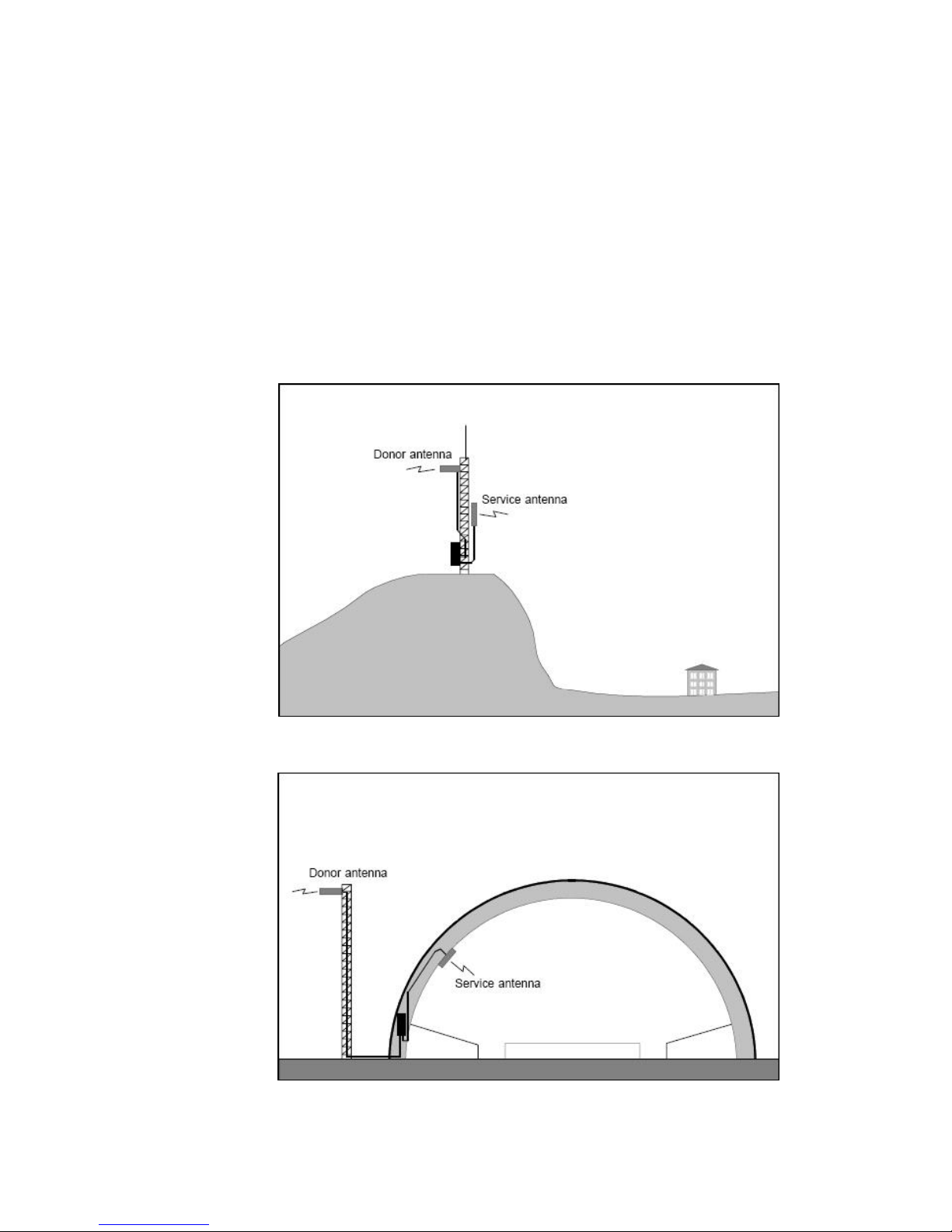
Repeaters are used to fill out uncovered areas in cellular mobile systems, such as base
station fringe areas, road tunnels, business and industrial buildings, etc.
A repeater receives signals from a base station, amplifies and retransmits the signals
to mobile stations. Also it receives, amplifies and retransmits signals in the opposite
direction. Both directions are served simultaneously.
To be able to receive and transmit signals in both directions, the repeater is connected
to a donor antenna directed towards the base station and to a service antenna directed
towards the area to be covered.
Figure 1 Outdoor Application
Figure 2 Indoor Application
Ver. 0 4
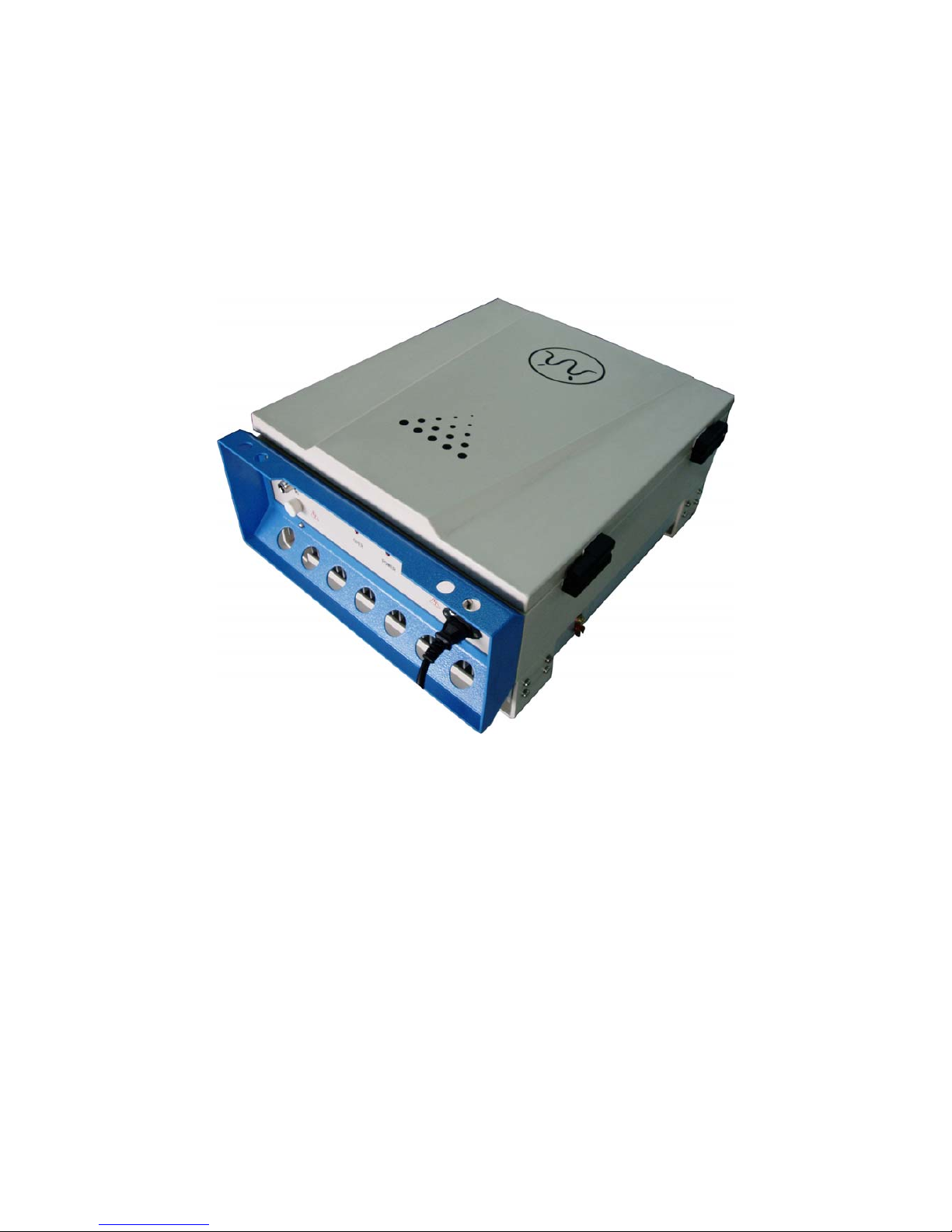
Longent dual-band selective repeaters with 2 adjustable bandwidths have filters that
can be set to various bandwidths. This repeater type is suitable for the most carriers that need
2 band blocks support in 800 MHz cellular band.
Figure 3 Longent Repeater
1.1. Product Features
Full Block A + A* or Block B + B* support
2 programmable bandwidth, 0.5 MHz to 20 MHz for each
RF output power in user definable, 30 dBm max.
Web interface for monitoring and control
Integrated RF module
Ver. 0 5
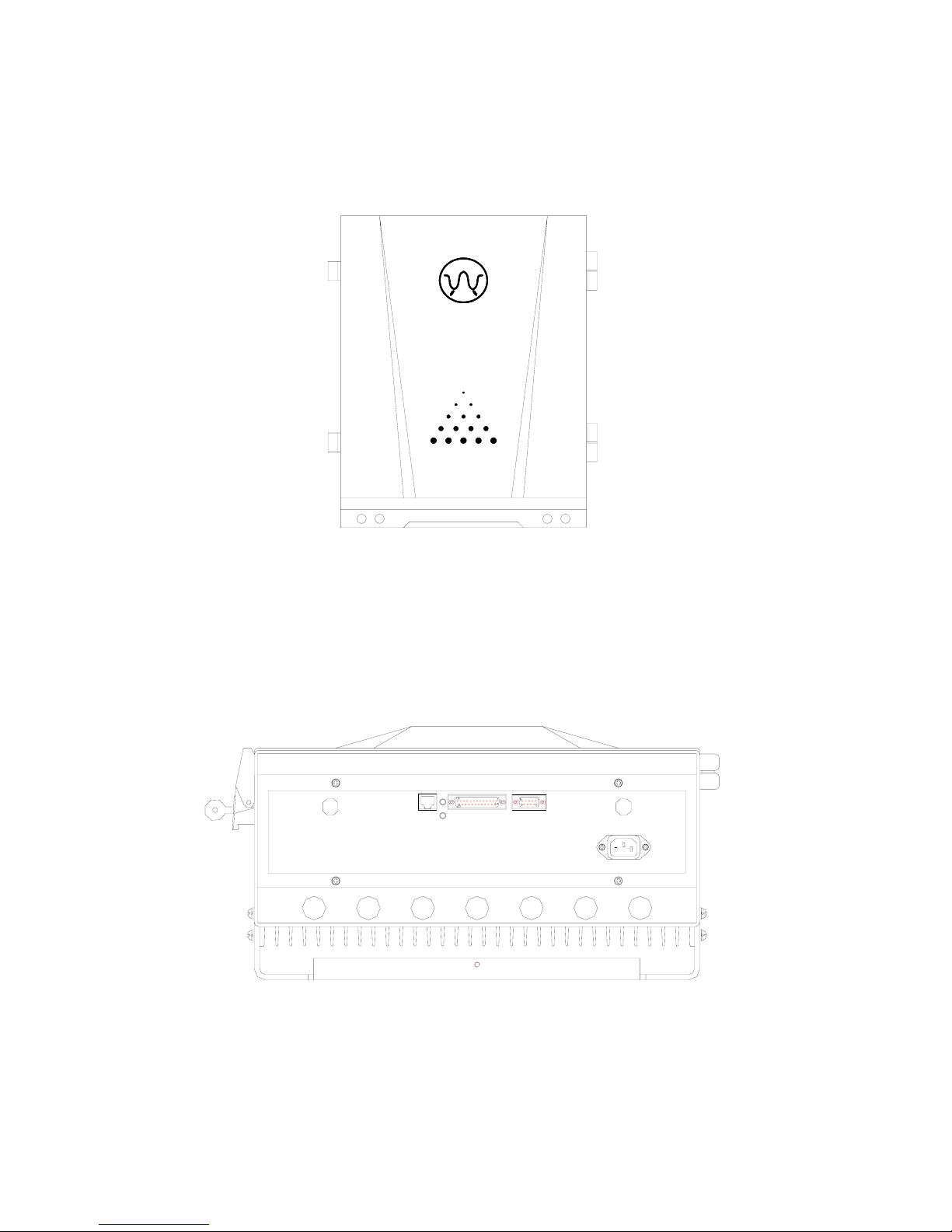
1.2. Front View
1.3. Bottom View
MS BSBS
AC
☺

Ver. 0 6
2. Specification
2.1. RF Specifications
Frequency Band 824 – 849 MHz, Uplink (Reverse Link)
869 – 894 MHz, Downlink (Forward Link)
Number of Bands 2
Bandwidth 0.5 – 20 MHz, Programmable
Gain Adjustment Range 55 – 85 dB (1 dB Steps)
ALC > 30 dB
Absolute Group Delay < 10 µs (8 µs Typical)
Output Power +30 dBm, Total
Maximum Input Power +13 dBm
(Non-destructive)
Out of Band Spurious Emission -30 dBm, max.
Selectivity < -20 dB @ +/-500 kHz out of band
< -30 dB @ +/-700 kHz out of band
< -50 dB @ +/-1 MHz out of band
Pass Band Ripple 6 dB
(Typical 3 dB @ +/-1 MHz departure from the
edge within the selected band)
Noise Figure at Max Gain 5 dB
VSWR < 1.5 : 1
2.2. Electrical Specifications
Power Supply Voltage (default) 115 V AC
Power Consumption, max 200 W
DC Output of PSU 27 V, 12 V
2.3. Mechanical Specifications
Dimensions (W×H×D) 410 mm × 520 mm × 234 mm
Weight 23 kg
RF Connector N-type female
Signal Connectors RJ45 Modular Jack
DB25 female for 8 dry contact output
DB9 female for 6 dry contact input

Ver. 0 7
2.4. Environmental Specifications
Temperature Range -25 to +55 ℃
Humidity 95%, Relative
Casing Class IP53
2.5. Monitor and Control
Monitor
Output Power
ALC Attenuation
DGC Attenuation
PA Enable
PA temperature
VSWR
Band Setting
Used Gain
Control
ALC level
DGC Attenuation
PA Enable
Band Setting
Alarm
PA fault
High T emperature
Overpower
Synthesizer Fault (unlock)
PSU (Power Supply Unit) fault
Self-oscillation
VSWR Alarm
Door Open Alarm
External Alarm 1 ~ 6

Ver. 0 8
The signal from the base station is received via the repeater donor (BS) antenna and is
then forwarded through a directional coupler (DC). The signal passes a duplex filter
(DPX), is amplified in a low noise amplifier (LNA), and enters the band selective
amplifier (BSA), which has two parallel bands.
The first mixer stage on the BSA amplifier, which is controlled by a synthesizer,
converts the received frequency down to the IF frequency. The signal is then filtered
by a SAW band pass filter and amplified before it is fed to the second mixer stage,
controlled by the same synthesizer as the previous one, for converting back to the
original frequency. The SAW filter can be adjustable for each BSA has adjustable
bandwidth.
A detector on the PA measures continuously the output level. The signal from this
detector is used by the automatic level control, ALC, to supervise and, if necessary,
reduce the output power to keep it under a setting level.
The output signal passes duplex filter (DPX) and fed to the repeater service (MS)
antenna.
The uplink signal path, i.e. from the mobile station through the repeater to the base
station, is identical to the downlink path the other way round. Only some levels and
component values differ.

Ver. 0 9
3.2. Unit Descriptions
1. LAN and Dry Contact Interface board
2. PSU (Power Supply Unit)
3. MS Duplexer
4. Battery for Control Unit
5. Modem
6. BS Directional Coupler
7. Downlink Integrated Module
8. Uplink Integrated Module
9. BS Duplexer
10. Keypad and LCD
11. Control Unit board
12. Door Switch
1
2
3
4
5
6
7
8
9
10
11
N
+9V- ADJ
L
TS-SDY03- 27V/4AⅢ
+27 V
GND
GND
+27 V
+12V-ADJ
+12V-ADJ
GND
GND
PE
12

Ver. 0 10
4. Installation
A preferable site for the repeater is a tempered and ventilated place. If a repeater is
placed outdoor and can be exposed to direct sunshine, it is essential that the air can
circulate around the repeater with no obstacle.
Do not install or open a repeater at bad weather, such as intense rainfall, snowfall or
hail, storm or high wind, extremely low or high temperature and high humidity.
4.1. Mounting
1. Mount the provide bracket
Normally, the repeater is mounted on a wall. The mounting bracket is attached to a
wall using locking screws.
2. Hang the repeater
After attached the bracket, hang the repeater on the two upper supports and use one
M5 screw to fasten the repeater to the bracket.
M5 clamp screw

Ver. 0 11
4.2. Connection
1. Connect antennas
Connect the service antenna (MS) and donor antenna (BS) coaxial cables to the N
type female connectors marked with MS and BS.
2. Connect repeater to AC supply
Plug in the power connector on the bottom of the repeater.
3. Station ground
For the repeater supplied from mains, the mains outlet must be grounded. There is a
ground screw (M5) on the right side of the repeater.

Ver. 0 12
5. Operation and Maintenance
5.1. WEB Interface
5.1.1. Introduction
Longent repeaters allow you to read and modify the current status via local WEB as well as
remote SNMP.
The main program features:
Supporting local WEB interface to show and modify the status value
Supporting Http 1.0
Supporting remote SNMP to show and modify the status value
Supporting SNMP versions 1, 2.
5.1.2. Hardware and Software Requirements
Your computer must meet the following requirements to be able to connect the repeaters via local
WEB interface:
Pentium III processor 600MHz or higher
RAM 64 MB minimum, 256 MB recommended
SVGA-compatible video card supporting the resolution of 800*600 or higher
Network adaptor
A cross cable to connect your computer and the repeater
A WEB browser like IE 5.0 or higher
Installed and configured TCP/IP protocol stack
Your computer must meet the following requirements to be able to connect the repeaters via
remote SNMP:
Pentium III processor 600MHz or higher
RAM 64 MB minimum, 256 MB recommended
SVGA-compatible video card supporting the resolution of 800*600 or higher
A wireless CDMA Modem to connect through the Asynchronous and Fax Service
A SNMP Manager to append MIB file and read repeater

Ver. 0 13
5.1.3. Environment Configuration
The repeater uses the WEB interface to configuration. It used the static IP. Default IP is
192.168.15.15. So your computer must use the static IP too and the same subnet mask
(255.255.255.0). Your computer can use all the IP from 192.168.15.1 to 192.168.15.254 except the
repeater’s one (default is 192.168.15.15).
The method of configuration is following:
First, open the “start” menu. Choose the “Show all the connects” from the “Connect to”.

Ver. 0 14
In the “Network Connections” window, right click the “Local Area Connection” and choose the
“Properties” in the pop menu.

Ver. 0 15
In the “Local Area Connection Properties”, there is a “General” page. In this page, choose the
“Internet Protocol(TCP/IP)” in the “This connection uses the following items” list. Click the
“Properties” button.

Ver. 0 16
In this “Internet Protocol (TCP/IP) Properties” page, choose the “Use the following IP
address”, and sign the “IP address” like 192.168.15.14 and “Subnet mask” 255.255.255.0.
Others are empty.
Press the “OK” button, you’ll finish the configuration.
Now you can use a cross cable to connect your computer and the repeater. You can use IE to read
and notify the repeater information.
Exception: Access without the IP.

Ver. 0 17
5.1.4. Basic Operation of WEB Interface
After configuration is done, you’re able to use IE to read and notify the repeater information.
Open a new IE. Input the http://192.168.15.15
(or http:// IP you had set before) in the “Address”.

Ver. 0 18
The IE will show the “Station WEB” page.
1. Login
The first page is the “Login” page. You must input the correct user name and password.
Then you will press the “Enter” or “login” to login.

Ver. 0 19
2. Station View Page
If you input the right user name and password, the page will jump to the main page – “Station
View Page”.
This page has two parts divided by a line. The top part is the link to other operation page. The
other is showing the station information.
Operation page link:
Read Status Read the new information of the station.
Configuration Repeater Configure the station like ALC, DGC etc.
Configuration Repeater IP Configure the local IP for next connect.
Configuration Modem Configure the modem to the wireless connect.
Exit End of the using and return login page.
Station Information:
Basic Information Show the basic information of the repeater.
IP/Modem Information Show the IP and the Modem information.
Read Status Show the parameters of the repeater that can read only.
Configuration Show the parameters that you can change to change the repeater state.
Alarm Information Show the Alarm state that the repeater has then. If don’t have show “No
alarm”.

Ver. 0 20
3. Read the repeater status
If you press the Read Status link, wait for a minute, the page will refresh and show the new status
of the repeater.
Note: If there are some wrong strings or illegal strings on the page, please press the “refresh” on
the IE, and then the page will show the right one.
4. Configuration the repeater
If you press the Configuration Repeater link, you will in the Configuration Repeater page. In
this page you can change the basic information and the settable information.
There are two links in the Configuration Repeater:
View Page Return the view page and do nothing of configuration.
Exit End of configuration, do nothing of configuration and return the login page.
Two parts you can Configuration:
Basic Information Setting Change the basic information of the repeater.
RF Parameters Setting Change the parameters of the repeater and the repeater will
work as the input.
If you finish changing, you will press “Enter” or “Set” button to affirm the change. Please wait
for a moment, and then the page will jump to the View Page and show the new status.
Note: If there are some wrong strings or illegal strings on the page, please press the “refresh” on
the IE, and then the page will show the right one.

Ver. 0 21
5. Configuration the repeater IP
If you press the Configuration Repeater IP link, you will in the Configuration Repeater IP
page. In this page you can change the IP that you next time connect to.
There are two links in the Configuration Repeater:
View Page Return the view page and do nothing of configuration.
Exit End of configuration, do nothing of configuration and return the login page.
The input box has the IP now. You can input the new one and press “Set” to affirm.
Note: If there are some wrong strings or illegal strings on the page, please press the “refresh” on
the IE, and then the page will show the right one.

Ver. 0 22
6. Configuration the Modem
If you press the Configuration Modem link, you will in the Configuration Modem page. In this
page you can change the IP that you next time connect to.
There are two links in the Configuration Repeater:
View Page Return the view page and do nothing of configuration.
Exit End of configuration, do nothing of configuration and return the login page.
The input box has the modem information. You can input the new one and press “Set” to affirm.
Note: If there are some wrong strings or illegal strings on the page, please press the “refresh” on
the IE, and then the page will show the right one.
7. Exit
If you don’t want to do the read or configuration, you can press the “Exit” to end of you operation
and do nothing of the configuration.

Ver. 0 23
5.2. Keypad Interface
To be continued

Federal Communications Commission Statement
This equipment has been tested and found to comply with the limits for a Class
B digital device, pursuant to part 15 of the FCC Rules. These limits are
designed to provide reasonable protection against harmful interference in a
residential installation. This equipment generates, uses and can radiate radio
frequency energy and, if not installed and used in accordance with the
instructions, may cause harmful interference to radio communications.
However, there is no guarantee that interference will not occur in a particular
installation. If this equipment does cause harmful interference to radio or
television reception, which can be determined by turning the equipment off and
on, the user is encouraged to try to correct the interference by one or more of
the following measures:
-Reorient or relocate the receiving antenna.
-Increase the separation between the equipment and receiver.
-Connect the equipment into an outlet on a circuit different from that to which
the receiver is connected.
-Consult the dealer or an experienced radio/ TV technician for help.
CAUTION:
Any changes or modifications not expressly approved by the grantee of this
device could void the user's authority to operate the equipment.
 Loading...