

Page 1

Telesto Private Wire Modem
Manual
Page 2

Page 3

Telesto P rivate Wire Modem Manual
Page 4

Revision History
Filenames are:
G:\Company\Manuals&graphics\Manuals\ReferenceManual\Components\Telesto_modem\Private
Wire\Remote\RevA\CompleteManual\TelestoPwModemCover.lwp
G:\Company\Manuals&graphics\Manuals\ReferenceManual\Components\Telesto_modem\Private
Wire\Remote\RevA\CompleteManual\TelestoPwModemManual.lwp
G:\Company\Manuals&graphics\Manuals\ReferenceManual\Components\Telesto_modem\Private
Wire\Remote\RevA\CompleteManual\TelestoPwModemTitle.lwp
Rev Date Author Description
A May 6, 2002 R. Catalfamo Initial release.
Approval: ________________________________
Page 5

Configuration
Theory of Operation
Table of Conten ts
Telesto Private Wire Modem 1
1. Introduction
2. Organization of this Manual
3. Unpacking & Post Delivery Inspection
4. Technical Description
5. Servicing
Basic troubleshooting ........................................................................................
Appendix A - Connector Pinouts
...................................................................................................
............................................................................
............................................................
.....................................................................................
.........................................................................................
................................................................................................
......................................................................................................
.......................................................................
Appendix B - Outline and Installation Drawing
....................................................
3
5
7
9
9Overview of the Hardware ...................................................................................
9
11
15
17
19
Appendix C - Technical Specifications
...............................................................
21
Page 6

This page intentionally left blank.
Page 7

1. Introduction
Telesto Private Wire Modem 3
Telesto Private Wire Modems work in conjunction with Europa digitisers, greatly extending the
aperture of Nanometrics ter restrial Callisto networks.
It is strongly recommended that you read the entire manual before commencing testing,
configuring, or using the Telesto. On the following pages you will find a wealth of information
regarding all aspects of the Telesto modem. Please read the instructions carefully.
If you have problems or need technical support, please submit requests for technical support by
e-mail or fax. When communicating your problem to us please give as much information as
possible and inclu de "evidence" of the problem. This allows us to reproduce the pro blem in our
laboratories and to find a solution to your problem.
Introduction
by e-mail: [email protected]
by fax: To: Support at fax (613) 592-5929
by phone: Please ask for Support at (613) 592-6776
Nanometrics Inc.
250 Herzberg Road
Kanata, Ontario Canada
K2K 2A1
Page 8

This page intentionally left blank.
Page 9

Telesto Private Wire Modem 5
Organization of this Manual
2. Organization of this Manual
This manual is organized in these major sections:
Chapter 1 Introduction Introductory notes to this manual.
Chapter 2 Organization of this Manual Notes on how to use this manual.
Chapter 3 Unpacking and Identifies components and
Post Delivery Inspection references an "as-shipped" section.
Chapter 4 Technical Description Description of features
Chapter 5 Servicing Recommended maintenance and
Appendices These list pin connections, outline & installation drawings and the Telesto
Private Wire Modem Technical Specification
and technical specifications.
repair procedures.
Page 10

This page intentionally left blank.
Page 11

Telesto Private Wire Modem 7
Unpacking & Post Delivery Inspection
3. Unpacking & Post Delivery Inspection
Open and inspect the shipment for possible damage. Carefully check each item for damage or
defects. The following list includes items generally included with the Telesto modem. This list can
vary from application to application. To determine the exact list of items included in your shipment
refer to the shipping documents.
The system may include one or more of the following:
1. Telesto Private Wire Modem
2. Power cable
3. Telesto Private Wire Modem Manual
4. As-shipped Sheet
5. OEM Modem Manual
Checking the As-Shipped Sheets
Please study the as-shipped data sheet to determine the exact configuration of the Telesto modem .
The as-shipped sheet lists the serial numbers of the parts shipped and the exact configuration of
the parameters associated with your hardware. This determines how your Telesto modem operates
when first powered-on and how it functions within your network.
Page 12

This page intentionally left blank.
Page 13
Technical Description
Telesto Private Wire Modem 9
4. Technical Description
Overview of the Hardware
The Telesto Private Wire Modem is the interface at a remote seismic site between the Nanometrics
Europa digitiser and the telephony communications network. The Europa digitises analog seismic
signals, packages and outputs this information in the form of a serial data stream of a proprietary
format. The Telesto modem integrates all the hardware necessary to receive data from the Europa
digitiser and sends these data to the network central site. It also provides for the reverse flow of
data by receiving various network management information from the central site and passing it to
the Europa digitiser. Optionally, the Telesto Private Wire Modem provides power to its associated
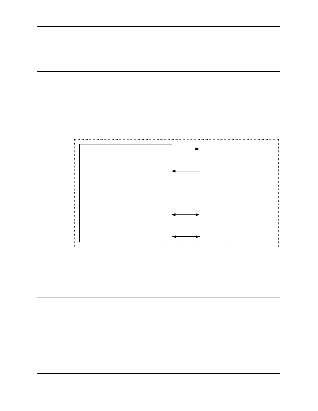
Europa digitiser . The general function of the Telesto is shown in Figure 1.
Optional 12 VDC out (to Europa Digitiser)
POWER
24 VDC in (from external power supply)
Theory of Operation
The two main functions of the Telesto modem are to interface the data from the Europa digitiser to
the leased-line telephony network and, optionally, to supply power to the Europa digitiser. The
functions are performed by a Printed Circ uit Board (PCB) mounted inside the Telesto enclosure .
This PCB contains two principal components - a modem and three DC/DC converters. Other
ancillary comp onents include flex circuits which interface the PCB to the Telesto front panel
connectors. The main functions are described below.
TELESTO
PRIVATE WIRE
MODEM
RS-232 serial data (to/from Europa Digitiser)
DATA
Telephony traffic (to/from leased-line telephone network)
Figure 1: Telesto Private Wire Modem, General Function
Interfacing serial data to the leased-line telephony network
The serial data stream produced by the Europa digitiser uses an RS-232 physical layer protocol.
This format is not suitable for transmission over a leased-line telephone network because of signal
Page 14

Technical Description
Telesto Private Wire Modem 10
levels, voltages , bit duration, etc. In order to efficiently couple the RS-232 data to the telephone
network a device known as a modem (MOdulator/DEModulator) is used to transform the RS-232
digital data into an analog signal which can be efficiently carried on the telephony channel. By
varying the properties of the analog signal such as signal amplitude, phase and duration, one can
efficiently pack the RS-232 data onto the telephony channel. The telephony channel then carries
the data traffic to the eventual destination. At the receiving end (in this case, the central station)
the telephony signal is transformed back to RS-232 format which can then be used by DTEs (Data
Terminal Equipment) such as computers and data processing equipment.
Therefore, the Telesto modem at a remote site must be paired with a corresponding modem at the
central site. Both of these units perform the same function - they transform the local data stream to
a form suitable for transmission on the leased line tel ephone network. Because data flow can occur
in both directions, i.e., to/from a remote site, the Telesto private wire modem is a full-duplex device.
This allows seis mic data to be sent continuously to the central data acquisition site while also
providing a return path for retransmission requests from the central site.
Both the remote site Telesto modem and its counterpart at the central site perform error detection
and correction which may have been caused by noise on the telephone channel. This function is
performed transparently, i.e., neither the Europa digitiser nor the central site data acquisition
equipment have knowledge of this real-time error correction.
The Telesto modem has been designed to require no “handshaking” between itself and the data
device connected to it, e.g., Eu ropa digitiser. Only 3 signal lines are necessary to transmit/receive
data over the leased-line telephone network with the Telesto; thes e are Tx (Transmit), Rx (Receive)
and GND (Ground). Data to be transmitted is simply placed on the Tx line while data to be received
is obtained by monitoring the Rx line; GND serves as an electrical return path.
Power Conversion (Optional)
Because the available power at the remote site is 24 VDC, the Telesto Private Wire Modem
converts this voltage to a 12 VDC level re quired by the Europa digitiser. As well the Telesto’s
internal electronics require differe nt voltage levels. The power conversion is accomplished inside
the Telesto with the use of 3 DC/DC converters. These solid state devices provide 15 VDC, 12 VDC
and 5 VDC. The 12 VDC is made available to the Europa Digitizer via a MIL connector on the front
panel of the Telesto enclosure.
Page 15
Configuration
Telesto Private Wire Modem 11
The Telesto Private Wire Modem requires configuration in order to properly integrate it into the
seismic network. This config uration assumes that the telephone network is a 4-wire leased line
system. Because the Telesto Modem at the remote site is paired with a corresponding unit at the
central site, it is important to configure the remote site Telesto Modem in ANSWER mode (the
central site modem, in this case, is in ORIGINATE mode). Both the hardware and firmware
configurations are detailed below.
Hardware Configuration
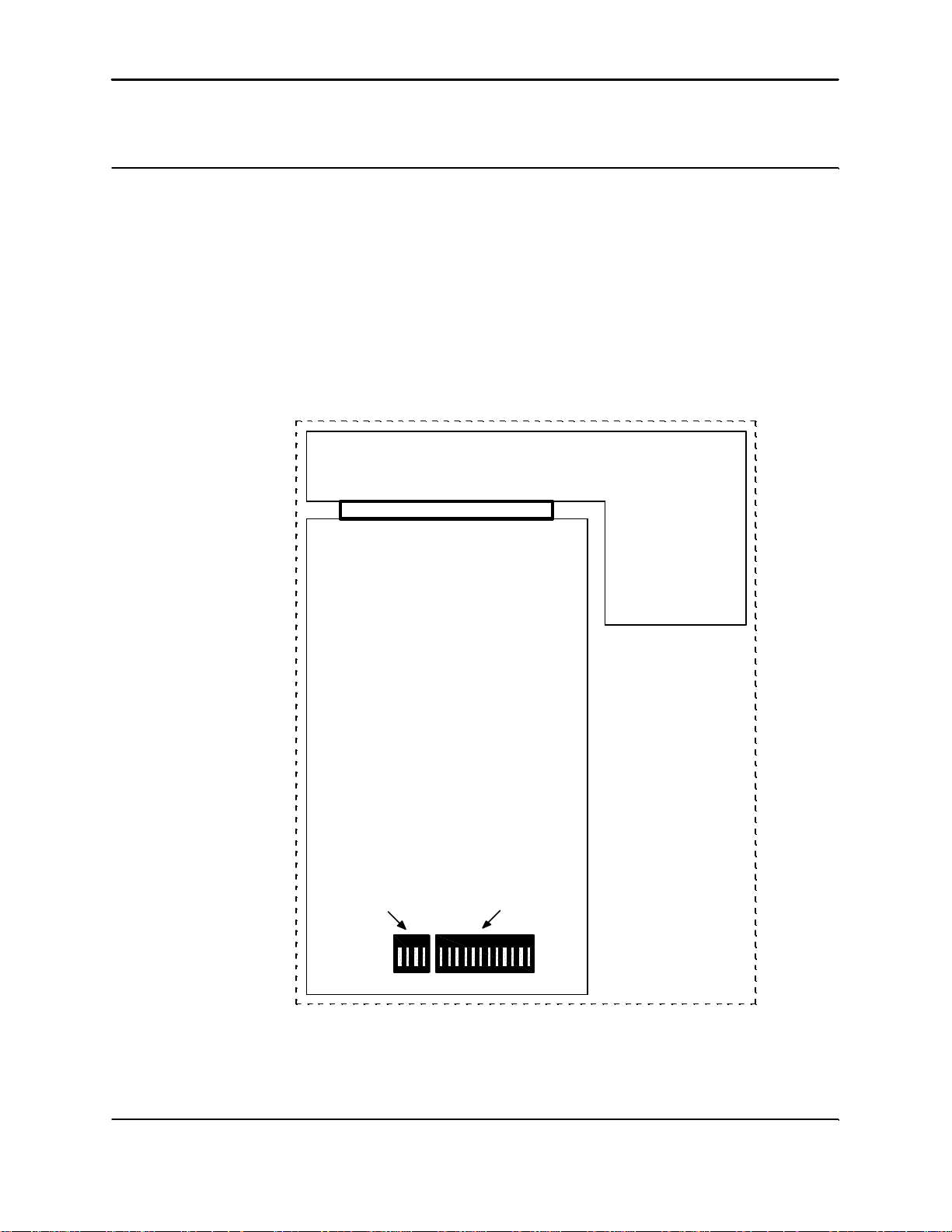
Inside the Telesto Private Wire Modem can be found a telephone modem PCB (model Multitech,
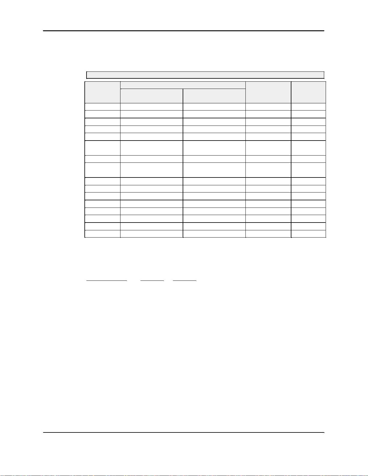
MT2834BLRe) as shown in Figure 2. The PCB has two dip switches containing a total of 16
switches which must be configured as in Table 1.
Technical Description
TELEPHONE MODEM
PCB
switches
13 to 16
13 1
Figure 2: DIP Switch Location on Telephone Modem PCB
switches
1 to 12
OPENOPEN
Page 16
No.
Telesto Private Wire Modem 12
6
8
Technical Description
TELEPHONE MODEM DIP SWITCH SETTINGS
FunctionDIP Switch
DOWNUP
Maximum throughput
enabled
Command modem
disabled
Table 1: DIP Switch Settings (UP = OPEN, DOWN = CLOSED)
disabled
enabled
Manufacturer’s
Default
Telesto
Modem
downdownDTR forcedDTR from interface1
downupFlow control di sabledFlow control enabled2
downdownTx level = -9dBTx level = -15 dB3
upupUUCP enabledUUCP disabled4
downupAnswerOriginate5
upupMaximum throughput
downdownRTS forced onRTS normal7
downdownCommand modem
downdownRemote loopbackLocal loopback9
downupLeased lineDial-up10
downdownMT result codesAT result codes11
downdownAsynchronousSynchronous12
upupSee note belowSee note below13
upupSee note belowSee note below14
upupCD forced onCD from interface15
downdown4-wire2-wire16
NOTE:
Baud Rate(kbps) Switch 13 Switch 14
28.8 UP UP
19.2 DOWN UP
14.4 UP DOWN
9.6 DOWN DOWN
Firmware Configuration
Firm ware configuration allows the user to tailor such configurable param eters as data port rate, flow
control, error correction, etc. In this application, as a point-to-point private wire modem, the
following settings are required. The Telesto Private Wire Modem is shipped with this
configuration. The firmware configuration procedure is given below.
1. Ensure that the Telesto Private Wire Modem is undowered.
2. Remove the cover and gain access to the telephone modem PCB inside the Telesto Private
Wire Modem.
3. Configure the DIP switches as described above.
4. Change dip switch 10 to UP position.
Page 17
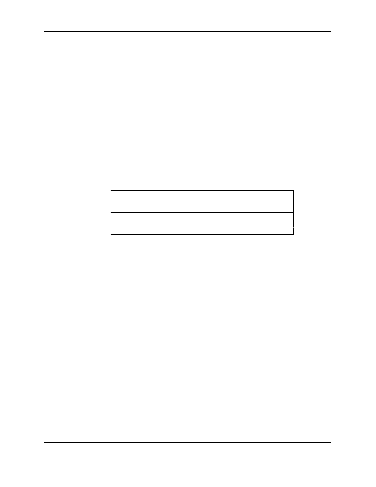
Serial port data rate = 9600 bps
$
sb9600
Data compression disabled
&e14
No flow control
&e3
No error correction
&e0
Function
AT Command
TELEPHONE MODEM “AT” COMMAND SETTINGS
Technical Description
Telesto Private Wire Modem 13
5. Connect the comms port of the Telesto Private Wire Modem to the serial COM port of a PC or
laptop computer.
6. Start a terminal emulator, e.g., ZOC, on the computer and configure it to the correct COM port.
7. Power up the Telesto Private Wire Modem.
8. Type in the following command (this is a sequence of “AT” commands) at the terminal
emulator:
at&e0&e3&e14$sb9600&w0
The modem should reply with: OK (displayed by the terminal emulator).
9. Reset the modem by typing atz in the terminal emulator. The modem should reply with: OK.
10. Type in atl5 at the terminal emulator. The modem will display the configured parameters.
Ensure that the above commands have configured the parameters correctly as shown in Table
2.
11. Power down the Telesto Private Wire Modem.
12. Change dip switch 10 to DOWN position.
13. The firmware has now been configured; reassemble the Telesto Private Wire Modem.
Table 2: Telephone Modem “AT” Command Settings
Page 18

This page intentionally left blank.
Page 19

5. Servicing
Telesto Private Wire Modem 15
Basic troubleshooting
The Telesto Private Wire Modem is always used as part of a network containing Europa digitisers.
Therefore troubleshooting the Telesto usually involves setting up some combination of
(digitiser,Telesto Modem,central site) equipment under laboratory conditions. In this manner the
commas port of the Telesto Modem can be checked for data continuity which is sufficient proof
that the Telesto Modem is operational.
Before you attempt any troubleshooting check all the connections, batteries and fu ses to rule out
the possibility that the malfunctioning is due to one of these items .
Unable to communicate with the Telesto Modem
If the Telesto Modem fails to send any data or, during firmware configuration, the terminal emulator
menu appears inaccessible on power-up, check both the settings of the terminal emulator and the
Telephone Modem PCB firmware. In most cases the cause is either a mismatch in baud rate settings
or the AT command settings in the modem PCB firm ware are incorrect.
Disassembly and Reassembly
There are two paired boards within the Telesto. The objective is to troubleshoot to the board level
and replace these boards. Attempt to identify the faulty PCB board pair by swapping in the
corresponding board pair from a working unit. The necessary tools are:
1. Phillips screwdriver.
2. Allan key 3 mm for socket head cap screws.
Servicing
Disassembly Instructions
1. Disconnect all the cables from the Telesto.
2. Remove the screws around the edge of the front plate of the enclosure box and pull
out the electr onics tray using two of the face plate connectors..
3. Remove the sma ller board by first unscrewing the only screw on the board and then
pulling out the board away from the edge connector.
4. Remove the other board by 1.unscrewing the 4 screws to the flex circuits attached to
the front panel connectors, 2. Pulling off each flex circuit from the board connector, 3.
unsrewing the 7 screws holding this board to the chassis .
Assembly Instructions
The assembly instructions are the reverse of the disassembly instruction. Make sure that the
repaired unit has the same configuration parameter values as the previously faulty unit. Refer to the
as-shipped sheets for the configuration parameters. After power up , check the following:
} The telephone PCB firmware menu is accessible.
} The Europa Digitiser is transmitting data.
} Re-requested packets from the central site are received by the central site.
Page 20

This page intentionally left blank.
Page 21
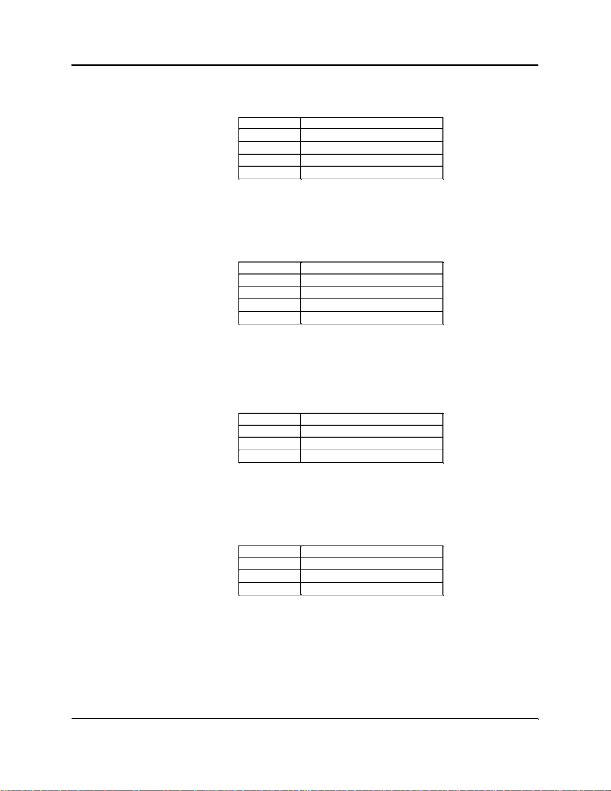
Appendix A - Connector Pinouts
Dgnd
T
Shield
SHD
leased 4
C
Earth
B
Earth
B
Telesto Private Wire Modem 17
RDH
TDG
Table 1: Comms Connector Pinout
leased 1A
leased 2 (Dial 1)B
leased 3 (Dial 2)D
Table 2: Leased Line Connector Pinout
Signal NamePin Number
Signal NamePin Number
Signal NamePin Number
Battery+A
Battery-C
Table 3: Input Power Connector Pinout
Signal NamePin Number
Battery+A
Battery-C
Table 4: Output Power Connector Pinout
Page 22

This page intentionally left blank.
Page 23
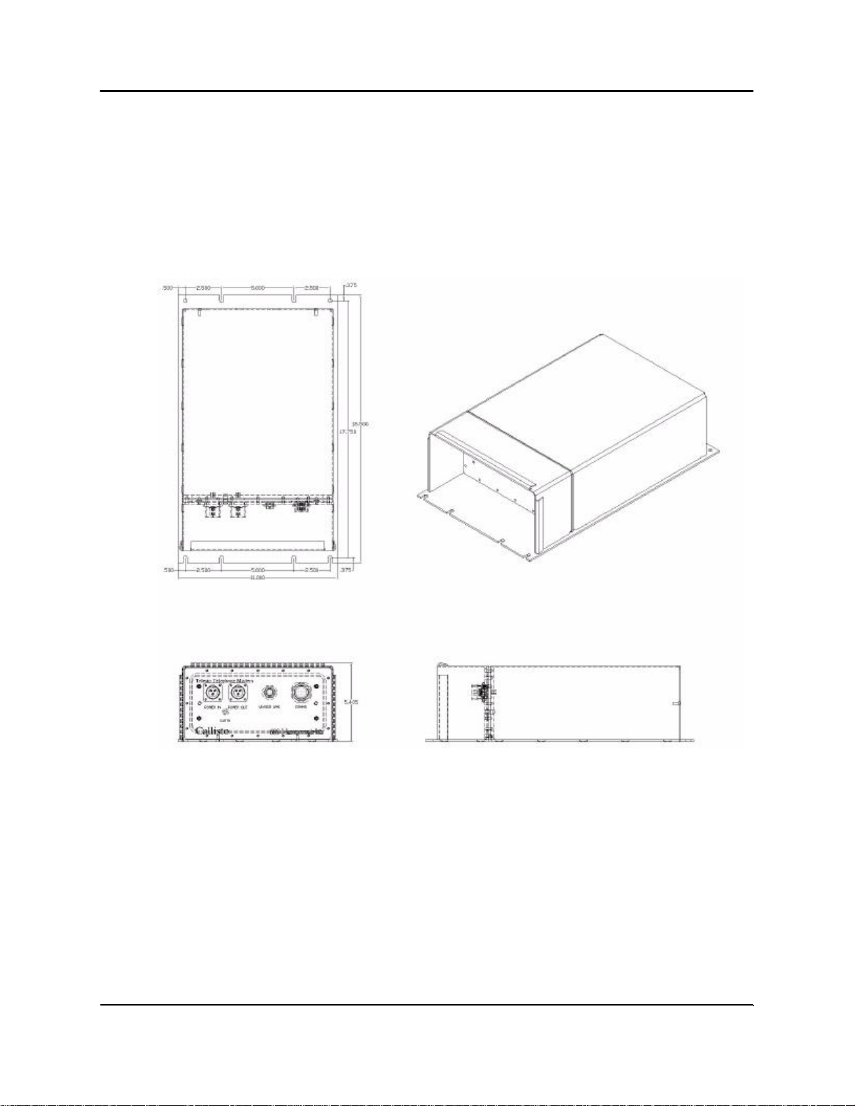
Appendix B - Outline and Installation Drawing
Telesto Private Wire Modem 19
Page 24

Appendix C - Technical Specifications
Telesto Private Wire Modem 20
Description
The Telesto Private Wire Modem is an interfacing unit between an RS232 line and an analog
private wire line (dedicated telephone line). At one end it connects to the serial data port (port 2) of
the Callisto Europa digitiser and at the other end to a 2 or 4 wire analog telephone line. The Telesto
is powered from a 24 Vdc power source and provides 12 Vdc to the Callisto Europa digitiser.
Specifications
Power Consumption 15 W (Typical)
Supply voltage 24 Vdc
Voltage Range 22-26 VDC
Surge Level no voltages above +/- 30 VDC
Interfaces
To Callisto Europa: RS232 with RTS/CTS data flow control
To telephone line: analog private wire on 2 or 4 wires
Baud rate: 19.2K and below
Standards: Data: Enhanced V.34, V.34, V.32bis, V.32,
V.22bis
Error Correction: V.42
Data Compression: V.42bis, MNP® 3 & 4
& Class 5
Environment
Housing Rugged waterproof aluminum enclosure
Size 469.9 mm L x 279.4mm W x 137.2mm H (18.50" L x 11.00"
W x 5.40" H)
Weight 3 kg (6 lbs)
Connectors RS-232, 19 pin cicular
Power, 3 pin
Telephone line, 4 pin circular
Environment meets or exceeds protected outdoor specification, see
Nanometrics document 13065
Page 25

Included Parts
Telesto Private Wire Modem 21
Telesto Private Wire Modem
Power Mating connector
Notes
1. See Nanometrics document 13005 for physical characteristics.
2. The unit must be properly grounded with a ground wire connected to the grounding lug
on the front panel.
 Loading...