

Teleste UHC-P User Manual
EASITM Accessories
User Manual
Teleste Corporation
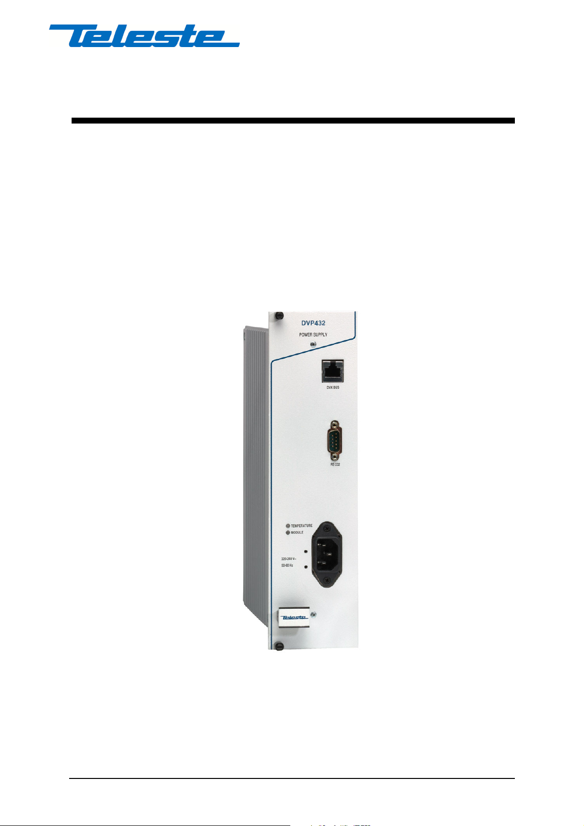
DVP432
DVP432 User Manual, 59300088, rev004
Power Supply

Contents
Introduction 2
General .....................................................................................................................................................2
Installation 4
Quick Instructions ....................................................................................................................................4
Mechanical Installation ............................................................................................................................5
Connectors................................................................................................................................................5
Indicators..................................................................................................................... .............................6
Using several DVP’s in parallel to implement back-up ...........................................................................6
Configuring the DVP432 7
General .....................................................................................................................................................7
Establishing a Data Connection................................................................................................................7
Starting CATVisor Commander...............................................................................................................8
CATVisor Commander - Connected Window .........................................................................................9
Configuring the units using CATVisor Commander..............................................................................10
DVP432 Configuration Display 12
General ...................................................................................................................................................12
Status Page .............................................................................................................................................13
Current Values Page............................................................................................................ ...................15
Measured values at the moment...............................................................................................15
Min & Max Page....................................................................................................................................17
Measured maximum and minimum values ..............................................................................17
The Fans Page ........................................................................................................................................18
Fan Control ..............................................................................................................................18
The Properties Page................................................................................................................................19
Legal Declarations 20
Copyright Acknowledgements...............................................................................................................20
Trademark Acknowledgements..............................................................................................................20
DVP432 User Manual, 59300088, rev004 Contents • i

Introduction
General
The DVP432 is a power supply for the EASITM rack
installations. It features enhanced EMC protection, output
voltage fine-tuning and stabilisation. Two logically controlled
long life fans gives the unit optimal cooling and thus further
increased reliability.
The DVP432 is using the primary switch mode technology
providing a wide input voltage range, high efficiency and
reliability. It is short circuit and over temperature protected and
it includes the PFC (Power Factor Correction). Additionally,
the outputs are diode protected to allow two or several units to
be connected in parallel to implement backup functions. The
DVP432 also features fine-tuning capabilities and enhanced
stability for all of the three output voltage circuits.
NOTE! When two or several DVP power supplies are connected in parallel
to feed a common system it is especially important that the voltages are
fine-tuned so that the currents drawn from the voltage circuit in question
spreads evenly between the feeding supplies. This can be verified by
comparing the “Current (A)” values between power supplies used. See the
configuration displays for more information.
The specified output voltages and currents per circuit are 25V /
8A, 12.5V / 5A and 6.3V / 10A. These voltages are connected
to the EASITM -system via the DVX002 installation frame, so
no connection cables are needed. If an output has overload, the
built-in current limiting function begins to take effect at 25V /
9A, 12.5V / 5.5A and 6.3V / 12A. The 12.5V and 6.3V current
is drawn from the 25V output, so note that the total maximum
available power from all 3 outlets must not exceed 200W. All
the outputs are short circuit protected.
DVP432 User Manual, 59300088, rev004 Introduction • 2

The power supply has an electrical screening of class 1 and it is
intended for an indoor installation in a dry place. The unit must
not be installed in a place where it can be exposed to dripping
or splashing water. The operating voltage is 220…240 VAC,
50…60 Hz.
DVP432 User Manual, 59300088, rev004 Introduction • 3

Installation
Quick Instructions
• The DVP power supply unit is installed on the extreme left-
• Lock the unit into place, connect the mains power cable to a
• Connect a PC (with the CATVisor Commander software
•
• Start the CATVisor Commander. See that the unit is not
• No programming of the power supply itself is required. The
hand side of the DVX002 installation frames (positions
1&2), but it can also be installed to any other frame
position, if necessary. When the EASITM system consists of
several installation frames, each frame must have a bus
address specified (refer to the DVX002’s User Manual).
220…240 VAC, 50…60 Hz wall outlet and see that the
green “MODULE” -indicator of the unit is lit.
installed) to the DVX BUS connector on the front panel of
the DVP power supply using the DVX021 connection
cable.
indicating any alarms or warnings (Status page). Both of the
"TEMPERATURE" and "MODULE" -indicators on the
front panel should now show green.
system is now ready for installation of additional units.
Install and select the unit to configure and proceed by
filling in the required parameters according to the unit in
question.
DVP432 User Manual, 59300088, rev004 Installation • 4

Mechanical Installation
Place the DVP432 power supply into a DVX002 installation
frame equipped with a specified DVX bus address (see frame
User Manual). The unit is normally placed into the first frame
position on the left-hand side, but it also can be put to any other
frame position, if necessary. Lock the module into place using
the screws on the module front panel.
Note! The unit must not be installed in a place where it is exposed to
dripping or splashing water!
Connect the mains power cable to a 220…240 VAC, 50…60
Hz wall outlet. A securing plate (included in the packing) can
be mounted to secure the connection. See that the green
“MODULE” -indicator on the front panel of the unit is lit and
that the “TEMPERATURE” -indicator also shows green. No
programming of the power supply itself is required. The system
is now ready for the installation of additional units.
Connectors
On the front panel of the unit there are RS485 and RS232
interfaces with a data bus. The RS485 (DVX BUS) -connector
is used to connect the CATVisor Commander cable DVX021 to
program the DVX units powered by the PSU, or just to monitor
the DVP power supply functions. The connection between the
CATVisor Commander (PC) and the PSU (and the EASITM
module) can also be established through a standard null-modem
cable by connecting it to the RS232 connector.
The blank F-connector on the backside of the unit has no RFsignalling, its purpose is to enhance grounding.
DVP432 User Manual, 59300088, rev004 Installation • 5

Indicators
The “MODULE” -indicator normally shows green, turning to
flashing green when software or a programmer addresses the
module. If the module have alarm(s), the indicator shows red.
The “TEMPERATURE” -indicator should also show green. If
the indicator turns to yellow, the unit temperature has already
risen above the error flag temperature (see table) and the output
power is switched off until the temperature is back to the
normal level. Possible reasons for the overheating are overload,
poor ventilation or too high environmental temperature. The
specified environmental temperature range for the power
supply unit is from -10°C to +45°C.
Ensure the sufficient supply of cooling air by installing passive
ventilation units (CVU014) or leaving at least 10 cm of free
space above and below each installation frame. The active fan
unit DVX911 can also be used if necessary.
Using several DVP’s in parallel to
implement back-up
When adding a second power supply to a EASITM system that
is already powered up and running, it is advisable to connect
the mains plug for the PSU to be added before it is inserted into
the rack. This is to ensure the stability of the other signal
processing units in the EASITM system.
When two or several DVP power supplies are connected in
parallel to feed a common system it is especially important that
the voltages are fine-tuned so that the currents drawn from the
voltage circuit in question spreads evenly between the feeding
supplies. This can be verified by comparing the “Current (A)”
values between power supplies used. See the configuration
displays for more information.
DVP432 User Manual, 59300088, rev004 Installation • 6
 Loading...