

Teleste MPH241, MPH242 User Manual
User manual – MPH241/242
MPH series video encoders
H.264 / MPEG-4 / MJPEG / MPEG-2 video encoders
for PTZ and fixed camera networking applications
MPH241 – 1-ch stand-alone video encoder
MPH242 – 2-ch stand-alone video encoder
SD, HD-SDI (1080p)
MPH200 series video encoders user manual, 59300463, rev002

Contents
MPH series video encoders introduction ............................................................................................................... 1
MPH series video encoders front and rear panel ............................................................................................... 2-3
Getting started .......................................................................................................................................................... 4
Quick instructions ............................................................................................................................................... 4
Device’s IP address ............................................................................................................................................ 4
MPH200 series models ............................................................................................................................................. 5
Ethernet interface ..................................................................................................................................................6-7
Local ports, electrical interfaces ........................................................................................................................ 6
Power over Ethernet (PoE+) option .................................................................................................................... 6
Up-link ports, optical interfaces (SFP) ............................................................................................................... 6
How to unplug or plug-in the SFP transceiver module ...................................................................................... 7
To unplug and plug-in the SFP module, follow these steps ............................................................................... 7
Some generic notes for successful optical connections: ................................................................................... 7
Management interface .............................................................................................................................................. 8
General .............................................................................................................................................................. 8
WebUI ................................................................................................................................................................ 8
ONVIF ................................................................................................................................................................8
CLI – command line interface ............................................................................................................................ 8
Web user interface (WebUI) ................................................................................................................................ 9-11
General .............................................................................................................................................................. 9
System requirements for WebUI ........................................................................................................................ 9
Operation ........................................................................................................................................................... 9
Starting WebUI session ................................................................................................................................... 10
User levels and permissions ............................................................................................................................ 10
MA IN PAGE ..................................................................................................................................................... 11
Event management system ............................................................................................................................... 12-13
MPH event management system ..................................................................................................................... 12
Event management for video ........................................................................................................................... 13
Event management for contact closure (digital I/O) ......................................................................................... 13
Conguring video channels ..............................................................................................................................14 -24
Video connection ............................................................................................................................................. 14
Video channel conguration ............................................................................................................................. 14
Video streaming methods ................................................................................................................................ 15
High-denition serial digital interface (HD-SDI) ............................................................................................... 15
Media prole (video) ......................................................................................................................................... 16
Video interfaces .............................................................................................................................................. 17
JPEG snapshot conguration .......................................................................................................................... 18
Video source and sinks ................................................................................................................................... 19
Video encoders ............................................................................................................................................... 20
Video stream multiplication .............................................................................................................................. 23
Video streaming performance .......................................................................................................................... 24
Conguring audio channels .............................................................................................................................2 7- 34
Conguring data channels ................................................................................................................................35-39
Conguring contact closure channels ........................................................................................................... 40-42
Event management ........................................................................................................................................... 43-44
Video analytics congurations ............................................................................................................................ 45
Metadata congurations ........................................................................................................................................ 46
Network settings ................................................................................................................................................ 47-4 8
Date & time settings ...............................................................................................................................................49
Device management ...............................................................................................................................................50
Services settings ............................................................................................................................................... 51- 53
User management ................................................................................................................................................... 54
Conguring ethernet switch ............................................................................................................................. 55 -74
Command line interface - CLI ...........................................................................................................................75 - 87
MPH200 specications ........................................................................................................................................... 89
Legal declarations .................................................................................................................................................. 90

MPH series video encoders introduction
Stand-alone video encoder with 1 or 2 video inputs, bi-direc-
tional data, audio & contact closure channels + Ethernet switch
General
MPH series encoders are ONVIF (Open Network Video Interface Forum)
compliant products. This provides wide interoperability with any ONVIF
compliant device or system.
Many similarities exist between the MPH series video encoders; the main
difference being the number of video channels available and the mechanics. MPH series video encoders are high performance video processing
products encoding real time video in mission critical applications for
customers in Transportation, City Center Monitoring, and Corporate
Security. MPH200 series encoders are temperature-hardened compact
size stand-alone video processing products in the MPX platform.
MPH200 series video encoders provides in addition to transparent link
of CVBS or HD-SDI video signal up to 1080p resolution (SMTP292M),
independently congurable general-purpose bi-directional asynchronous
data, bi-directional audio channels and bi-directional contact closure
channels. Additionally a layer 2 manageable Ethernet switch is integrated into the encoder. The Ethernet switch comes with four gigabit
ports and full-feature layer 2 switching functions such as RSTP, IGMP,
QoS and VLAN.
The encoded signal from MPH series encoder can be decoded with MPC/
MPX (except H.264) or VMX series HW and/or SW, as well as with industry
standard SW players such as Quicktime and VLC. The transmission is
accomplished over 10/100/1000BASE-T or 100BASE-FX (SFP) or
1000BASE-X (SFP) network utilizing IP/Ethernet streaming.
MPH series video encoders are equipped with the H.264, MPEG-4,
MJPEG and MPEG-2 video encoding engine. The default encoding
combination is H.264, MPEG-4 and MJPEG. MPEG-2 is an add-on
option, and it should be ordered separately.
The H.264 video encoding engine is compliant with the ISO/IEC 14496-10
(H.264@MP, BP, CBP) standard. The MPEG-4 video encoding engine is
compliant with the ISO/IEC14496-2 (MPEG-4@SP/ASP L5) simple prole
standard. The MJPEG video encoding engine is compliant with the ISO/
IEC 13818-2 (RFC 2435) standard. The MPEG-2 video encoding engine is
compliant with the ISO/IEC13818 (MPEG-2 MP@ML) standard.
Note! This product is under
development and Teleste
reserves the rights to alter
specications, features,
manufacturing release dates and
even the general availability of
the product at any time.
1 MPH200 series video encoders user manual
General-purpose asynchronous data channels are transferred separately from the encoded video signals.
Firmware version
The functionality and operation of the devices described in this manual
applies for rmware version 6.0.x.
MPH series video encoders front and rear panel
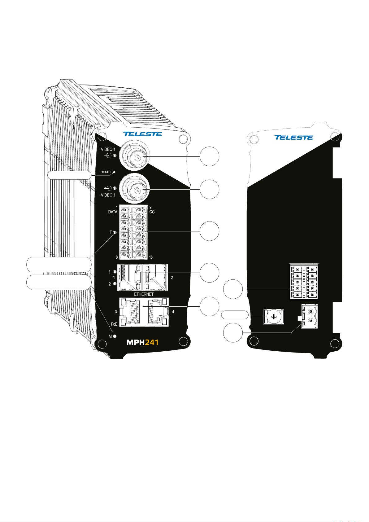
Front panel Back panel
MPH200 stand-alone encoder (example view from MPH241 device)
1
Reset button
2
T - Led. Terminal
server indicator led
M - Led. Power and
status indicator led
3
4
5
6
Ground
7
GND
AUDIO
1
5 10
12...24 VDC
6
_
+
2 MPH200 series video encoders WebUI user manual
CVBS
V
CVBS or
HD-SDI
x1
D
x2
A
x2
C
C
x2
E
x4
MPH241 signals.
MPH200 series video encoders mechanical connections
1. CVBS video input 1, or optional HD-SDI video input (BNC female) and
indicator led.
2. CVBS video input 2
Video loop through port for 1-ch versions and indicator led.
3. 16-pin screw terminal block and T indicator led:
Data interfaces, EIA RS422/485 (data1), EIA RS232 (data 2) /management interface (CLI) or general purpose serial port.
Contact closure interfaces (cc input 1, cc input 2, cc output)
4. Ethernet switch up-link interfaces, 2 x socket for SFP module (GE,
see a product catalogue for supported models).
5. Ethernet switch local port interfaces, 2 x 10/100/1000Base-T, RJ-45.
6. Audio interface (10-pin screw terminal block).
7. Power supply connector (2-pin screw terminal block, +12...28 VDC).
Reset button: Device software reboot and hard/soft factory defaults
restoration (see section Factory reset).
Ground: Device ground connection.
(BNC female)
for 2-ch versions or
V
x2
D
x2
A
x2
C
C
x2
E
x4
MPH242 signals.
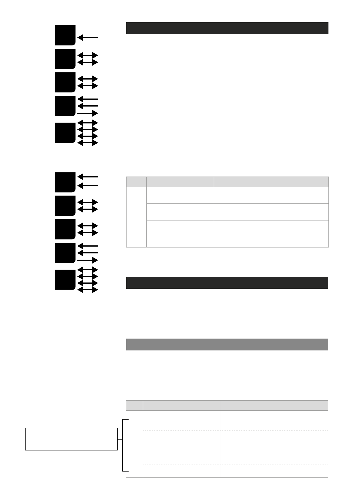
Led Colour Mode
OFF / Dark Power off
Yellow Device starts up
Red Device self-test failed
M
M - (module/power led) LED indicator operation. This LED indicates power
status, factory reset, interface activity.
Factory reset
The factory reset can be done via WebUI, CLI, or using the pinhole reset
button on the front panel of device. There are two types of factory resets;
Soft factory and Hard factory reset. The Soft factory reset restores all,
except IP conguration to the default factory settings. The Hard factory
reset restores all settings to default factory settings.
Reset button
Green Power on / Device is functional
Device is being accessed from any interface.
Blinking Green
Whenever device is accesed from WebUI, CLI or ONVIF
interface, led blinks 2s. During software update, LED will
blink throughout the rmware image transfer duration.
The reset pinhole is a button that resets the device to its original default
settings. To use this button, insert a stiff wire (such as a straightened paper
Note! If pinhole button is not
released within time window,
operation will cancelled.
3 MPH200 series video encoders WebUI user manual
clip) into the pinhole. If you release the button immediately the device will
reboot with current settings. But if you hold the button you can restore the
default settings as following table shows.
Led Colour Mode
6 x (short) green blinks at
boot time
2 x (short) red blinks
M
24 x yellow blinks at boot time
(after the 6 green blinks)
4 x (short) red blinks
Time window to select Soft factory reset.
If reset button is released in this time window, soft factory
reset is selected.
Soft factory reset shall be applied.
Wait until device has fully started (power led green).
Time window to select Hard factory reset.
If reset button is released in this time window, hard
factory reset is selected.
Hard factory reset shall be applied.
Wait until device has fully started (power led green).
Getting started
Quick instructions
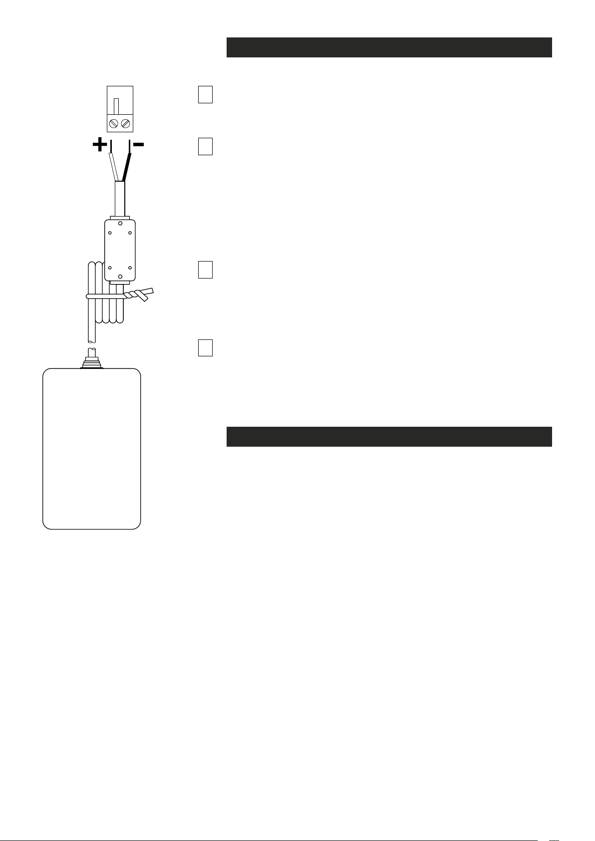
Install the temperature hardened stand-alone MPH200 series encoder to
1
the installation location. A +12 VDC supply voltage is provided by a CPS25x
series power supply (see example picture beside), or alternately through the
LAN cable (CAT5) when using Power over Ethernet (PoE+) technology.
2
3
Connect all needed signals to their respective connectors on the
device’s front panel:
• HD-SDI / CVBS video signals to the BNC female connector(s).
• Data and contact closure signals to the screw terminal connector.
• Audio signal(s) to the screw terminal connector.
• Ethernet network to Ethernet connectors.
Switch on the power and wait until the power led “M” lits green (start-up
time approx. 100 secs). This indicates that the device hardware is
operating properly and ready for usage.
Note! If led doesn’t lit green, refer to “M- LED indicator” section to
know the status of the device.
Log on to the device using the IP address assigned by DHCP server,
or locally from a Mgmt port (CLI) and then set all necessary settings in
the device.
4
Note! Device uses always two IP-addresses, one for encoder and an
another for internal switch management. By default device will
automatically assign IP addresses via DHCP.
contain DHCP server, then the MPH encoder shall use Zeroconf
(link-local) as DHCP fallback (see section below).
If network doesn’t
CPS25x series power
supply for MPH200 device.
Device’s IP address
There are two ways of assigning IP address to the MPH device. The IP
address can be automatically assigned via DHCP, or you can set it
manually as a static IP address. Factory default IP settings for the
device is DHCP enabled.
By default when you have DHCP server in the network, DHCP server
assigns an IP address automatically to the MPH encoder. The DHCP server
offers an IP address from its address pool when a device is starting up.
If DHCP server is not available device uses zero conguration (link-local
address) as DHCP fallback. With Zeroconf protocol MPH chooses an IP
address randomly in the IP range from 169.254.0.1 to 169.254.255.254.
Alternatively you can manually assign the IP address, subnet mask and
gateway address to the unit.
If there is no DHCP address in the network, the unit chooses randomly
an IP address from the private IP range 169.254.0.1 - 169.254.255.254.
In this case in order to nd the chosen IP address you have two options.
You can use Teleste MPH Discovery Tool to browse all the available
ONVIF compliment devices in the network, note that your PC IP address
should be in the same IP range. Second option is, connecting to the
MPH device locally via the serial port and use the CLI (Command Line
Interface) to see device IP address.
See section Network command to see how to change IP address via CLI.
4 MPH200 series video encoders WebUI user manual
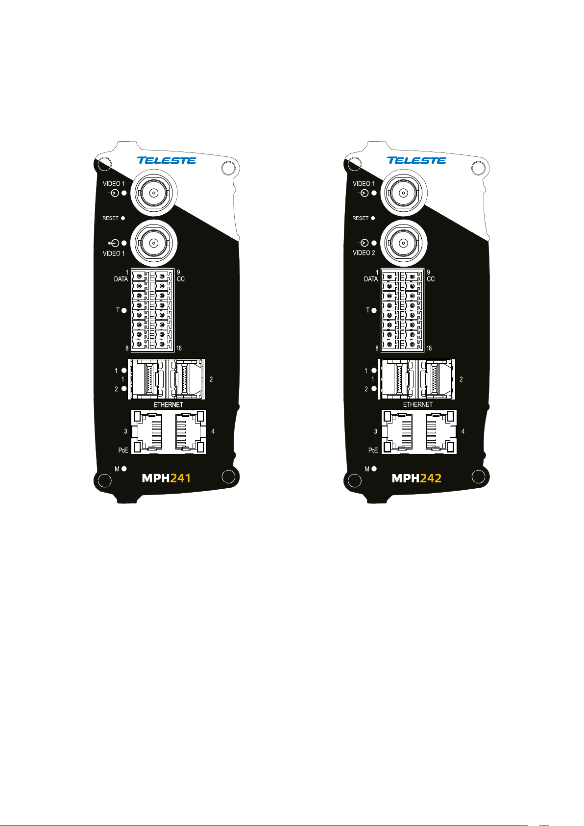
MPH200 series models
One video input (digital HD-SDI or analog CVBS). Two video inputs (analog CVBS).
MPH241 encoder supports both
digital HD (HD-SDI) and analog
CVBS video formats.
For HD-SDI operation the MPH241
needs to have the HD encoding
license MLH213 enabled.
5 MPH200 series video encoders WebUI user manual
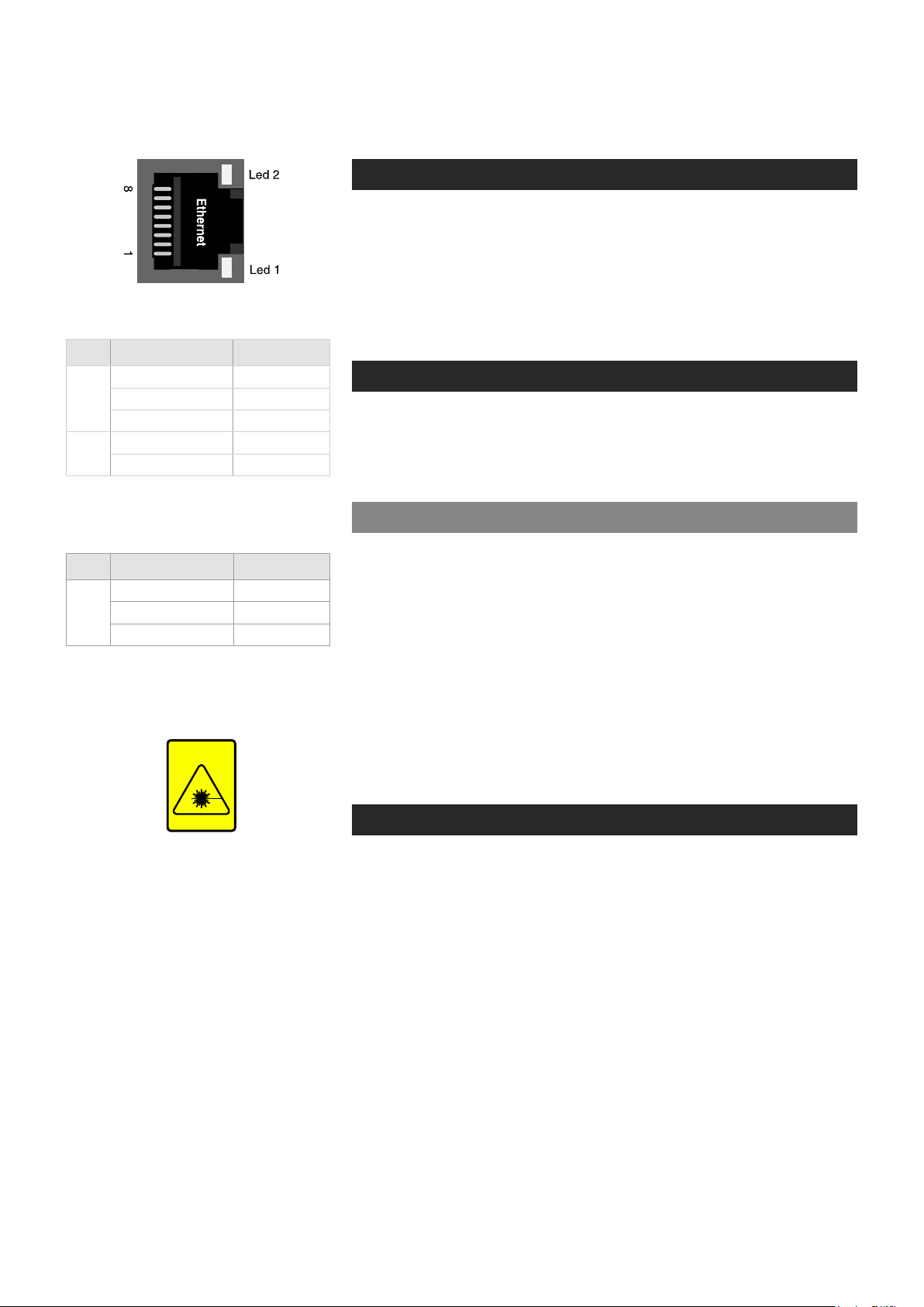
Ethernet interface
Electrical Ethernet connector (RJ-45).
Led Colour Mode
Green Link up
2
Blinking Green Trafc
OFF / Dark No link
Orange 1000 Mbps
1
OFF / Dark 100 Mbps
Ethernet port’s led indicator operation
(RJ-45 connector).
Ethernet connections
The unit has a built-in 4-port managed Ethernet switch and supports both
Fast Ethernet and Gigabit Ethernet connection speeds. Ethernet
interface type is either a xed electrical (copper), or has support for a
small form-factor pluggable transceiver (SFP) module. Supported SFP
transceivers are specied by Teleste. Please see the latest list of available
SFP products.
Local ports, electrical interfaces
Device include two (2) xed electrical Ethernet connectors. The electrical
Ethernet connector type is a RJ-45 female. The interfaces are supporting
10/100/1000Base-T operation (Gigabit Ethernet).
Power over Ethernet (PoE+) option
Led Colour Mode
Green Link up
SFP
Blinking Green Trafc
OFF / Dark No link
Ethernet port’s led indicator operation
(when SFP optical connector).
INVISIBLE LASER
RADIATION
CLASS 1
MPH200 series encoders supports PoE standard (PoE+ 802.3at class 4).
This means that the encoders can be powered through the LAN cable
without the need of individual power supplies. PoE is available from port
number three (3).
Requirements for the use of PoE:
• A Power over Ethernet (PoE) compliant switch or hub.
• MLH251 license activation.
Note!
MPH200 series device PoE port is only used to powered
device itself, it not provide output power to other devices.
Up-link ports, optical interfaces (SFP)
SFP modules for optical Ethernet operation are available with a variety of
different types (see the latest list of available SFP products), allowing users
to select the suitable module for to provide the required optical reach over
the available optical bre type. The optical connector type is LC/PC (single
or dual). Ethernet interface speed is 1000BASE-X (Gigabit Ethernet).
When installing the bre optic cable, do not exceed the minimum
bending radius when connecting cable to the system.
Optical Ethernet connection meets class 1 laser safety requirements of
IEC 60825-2: 2004 and US department of health services 21 CFR
1040.10 and 1040.11 (1990) when operated within the specied temperature, power supply and duty cycle ranges.
6 MPH200 series video encoders WebUI user manual
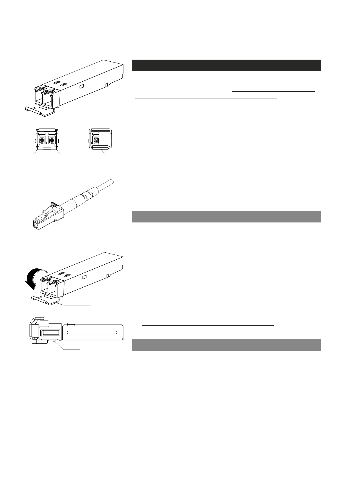
latch
2 fibre version 1 fibre version
Tx Rx Tx/Rx
SFP plug-in optical transceiver module.
How to unplug or plug-in the SFP transceiver module
If your up-link port requirements change, simply unplug the existing SFP
module, and plug-in the new module. The SFP transceiver modules
must be installed before the encoder is powered on. Installing SFP:
1. Switch off the unit supply voltage.
2. Mount the SFP transceiver to the unit (see bottom instructions).
3. Connect the bre optic cable(s).
4. Ensure that the remote end of the bre is already connected to an
active switch.
5. Switch on the unit supply voltage.
The SFP transceiver module has a bale-clasp latch that makes easier to
install or remove the module. Protect the SFP module by inserting a
clean dustplug into the module after you remove the ber cable. Be sure
to clean the optic surfaces of the ber cable before you plug the cable
into another module. When using 2 bre version SFP, select carefully
the correct optical port for TX and RX operation.
To unplug and plug-in the SFP module, follow these steps
Optical connector is the type of LC.
bale clasp
SFP module’s locking release points.
1. Open the bale clasp on the SFP module by pressing the clasp
downward until it is in a horizontal position.
2. Use a small at-blade screwdriver or
push on the hinge pin to unlock the SFP cage latch.
3. Grasp the SFP module by the bale clasp and gently pull it out of the
SFP cage
To plug-in the module:
1. Orient the transceiver with the bale clasp on the bottom, close the
bale clasp by pushing it up over the transceiver, then gently insert
the transceiver into the port until it clicks into place.
Note! Reboot the device when the SFP is changed.
.
other long, narrow instrument
to
Some generic notes for successful optical connections:
• Ensure that the ber patch cord is damage-free (ber condition can
be easily checked by a visible laser tester)
• Do not exceed the minimum bending radius of the bre
• Avoid sharp corners on cable shelves and in cable management
in overall
• Make sure that correct optical connectors are used
• Open connectors are always secured by dustcaps during maintenance
• Always before mating clean all connectors (wet cleaning by high
purity alcohol & drying, or dry cleaning with reel-based lint-free wipes,
ber adapters may require special ferrule end-face cleaning tools)
• Before making any visual inspections ensure that system has been
shutdown or no optical power is present
• For fault nding at least a optical power meter is required, a complex
ber cable environment may require use of an OTDR equipment.
7 MPH200 series video encoders WebUI user manual

9 10
11
12 13 14 15 16
Management interface
General
MPH encoders support web user interface (WebUI), ONVIF congura-
tion interface and command line user interface (CLI) for various conguration purposes.
WebUI
1 2
PC/
PSION
Receive
data
Transmit
data
System
ground
4 5 6 7 8
3
D9
female
2 6
3 7
5 8 Ground
Screw
terminal
MPH
encoder
Mgmt
output
Mgmt
input
MPH series video encoders can be fully congured using Web user inter-
face (WebUI). You can access the Web user interface via web browser.
ONVIF
MPH series video encoder support ONVIF (Open Network Video
Interface Forum) global interface (version 1.02, Prole S).
Local management connection (CLI)
and management cable (CIC506)
pinout (D9 female/screw terminal).
CLI – command line interface
MPH series video encoder include a command line interface (CLI) for
conguration purposes. The CLI is a text-based interface that allows the
user to interact with the operating system by entering commands and
optional arguments. CLI is accessible through any terminal emulator
application (e.g. Hyper Terminal or PuTTY). The command structure is
the same for all session types. A typical CLI usage is to access the
device IP address settings. By default the data channel 2 is set for CLI
usage. The data channel 2 can be set to normal RS232 data mode with
WebUI when needed.
Note! Data 2 channel can be set either general RS232 data
transport mode or CLI mode (not simultaneously). The default
factory setting is CLI mode (Hard and soft factory reset restores
the data channel 2 to the CLI mode).
Local CLI connection
The local CLI session can be establish via data channel 2 by using a
serial data connection (RS232) cable (type Teleste CIC506).
Note! Data 2 port must be set to CLI mode .
Remote CLI connection
8 MPH200 series video encoders WebUI user manual
Over the IP network you can make Telnet or SSH connection to open the
command line interface remotely. SSH protocol secures your data session.
Note! Remote CLI is always available through network, even
when data 2 is congured for non-CLI usage.
Web user interface (WebUI)
General
The MPH series video encoders can be fully congured using Web
user interface (WebUI). You can access the Web user interface via
your web browser, eg. Mozilla Firefox (recommended), Internet
Explorer, Apple Safari and Google Chrome. The Secure HTTP
(HTTPS, SSL 3.0 or TLS 1.0) feature is supported in MPH encoders.
System requirements for WebUI
• Network connection
• Ethernet cable
• Browser installed (Mozilla Firefox recommended)
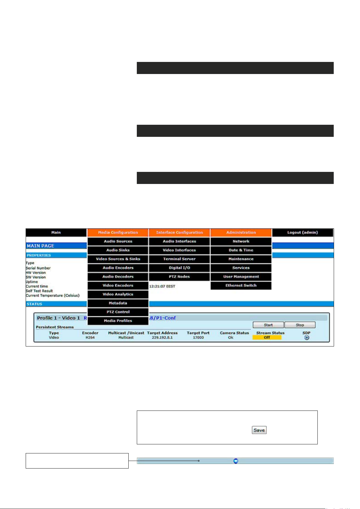
Operation
Web user interface consists of several menus and pages. Only one
page can be loaded at the same time. You can open a page by clicking
the related menu (see picture below).
The Web user interface has the following menu structure:
The information on conguration pages is shown in data elds or boxes.
The settings can be changed in the data elds and boxes having white
background. The unavailable or read-only options are grayed out. Place
the cursor in the desired data eld or box and enter a new setting.
Settings are entered by ticking a checkbox or clicking on a radio button,
by selecting from a pull-down list or by scrolling digits with the help of
spin buttons.
Press keyboard’s F5 button to refresh the WebUI page view.
When changing the settings, always click button to
conrm settings.
By clicking this button on a page
you can see more settings.
9 MPH200 series video encoders WebUI user manual
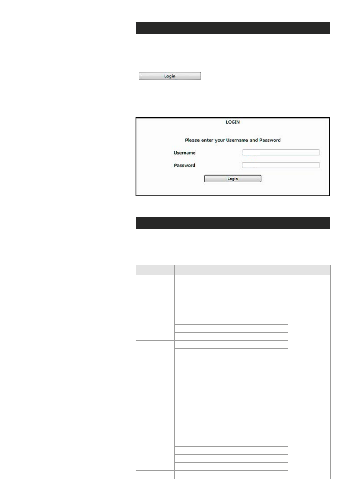
Starting WebUI session
To create a WebUI session, rst enter the device IP address into the
web browser’s address bar (see section Device’s IP address). The
following LOGIN window appears on the screen. Enter the required
username and password (see bottom) in the elds and then click
to continue --> Web user interface’s MAIN
PAGE appears on the screen.
The Web user interface session to MPH series video encoder is
now activated.
admin
admin
Login window with the default username and password (for administrator).
User levels and permissions
The user management supports three different user levels of which each
has specic priviledges as shown below. The individual usernames, passwords and approved user level can be changed via the WebUI and CLI.
Page Operation User Operator Administrator
General Access
SDP download
Main
Video & Audio
Encoder
Maintenance
User
Management
Ethernet switch Conguration
Log download
Start/Stop
RTSP link copy
General Access
Save
Cancel
General Access
Backup
Restore
Reboot device
Soft factory reset
Hard factory reset
Software upload
Software download
License install
General Access
Save
Cancel
Change password
Change user group
View/Edit other users
Add User
x
x
x
x
x
-
-
-
-
-
-
-
-
-
-
-
-
x
x
x
x
-
-
-
-
x
x
x
x
x
x
x
x
x
x
x
x
x
-
-
-
-
x
x
x
x
-
-
-
-
Read and write
access to all
pages and
all settings
10 MPH200 series video encoders WebUI user manual
Hint! You can open sdp le with the VLC player to
Shows installed and available
licenses for device.
view the stream, but notice the following requirements:
Stream port number should be even number. If you
are using multicast stream, ensure that you have set
valid multicast IP address. Make sure that windows
rewall is congured to allow this connection.
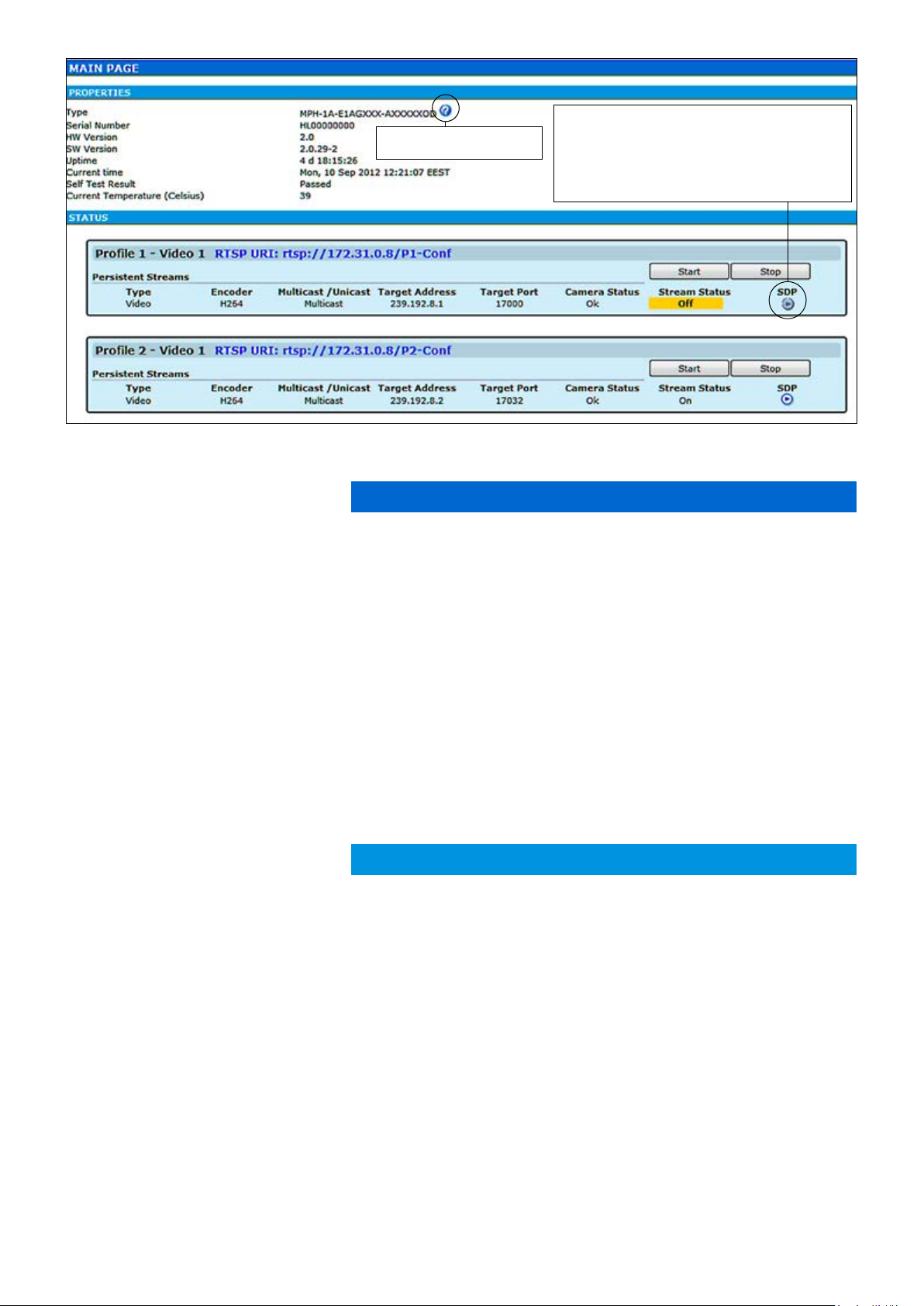
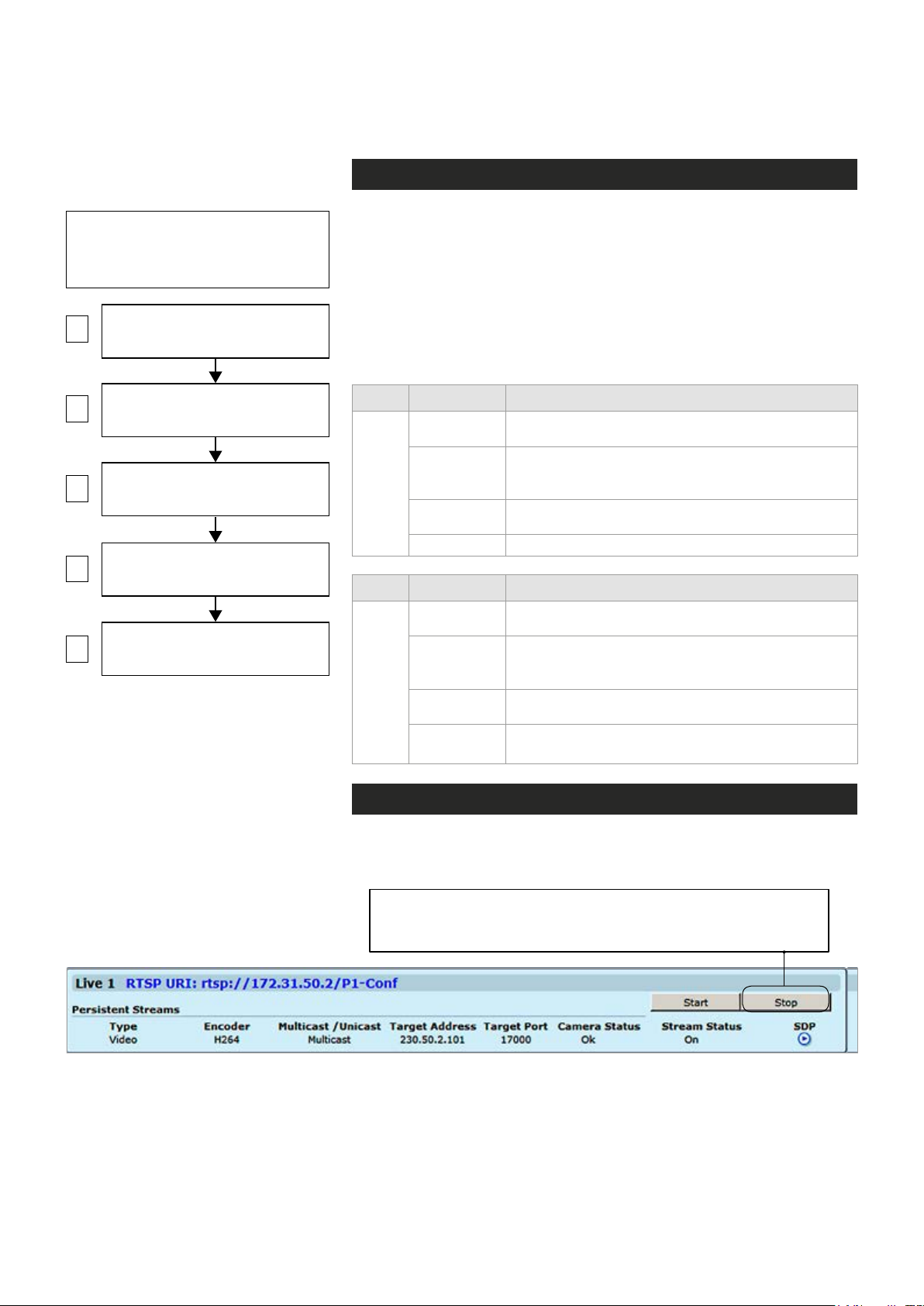
MAIN PAGE
The MAIN PAGE is opened after the WebUI session has been established to the MPH200 series video encoder.
Type:
Serial Number:
HW Version:
SW Version:
Uptime:
Current time:
Self Test Result:
Current Temperature:
Type:
Encoder:
Multicast /Unicast:
Target Address:
Target Port:
Camera Status:
Stream Status:
SDP:
MPH200 encoder contains maximum six (6) encoding proles, which
can be individually congured. On this page you can see each prole’s
current status and start/stop their video streaming.
PROPERTIES
Device type (conguration map code)
Device serial number
Device hardware version
Device rmware version
Device uptime
Device current time
Device test result
Current ambient temperature
STATUS
Here you can see each
Stream type (Video)
Encoding format (H.264/MJPEG/MPEG-4,MPEG-2)
Video transmission mode (multicast/unicast)
Multicast: Multicast IP address / multicast group
Unicast: IP address of receiving decoder
UDP port number
Camera status (Ok/No signal)
Video stream status (On/Off)
Link to SDP le (Session Description Protocol). The SDP le contains
stream parameters that are meant for 3rd party applications (e.g. SW
decoders) to open/view the stream. SDP-link requires that video streaming is active.
prole’s current status.
Download short term logs:
Download long term logs:
11 MPH200 series video encoders WebUI user manual
Debug log le
Debug log le
Event management system
MPH event management system
MPH encoders internally controls events as specied by ONVIF. Events
are generated from Digital IO inputs, motion detection, tampering
detection and video signal loss and each of those generate event with
different Topic. In addition to event topics, events contain data describing the event such as the video interface related, amount of motion and
threshold, etc.
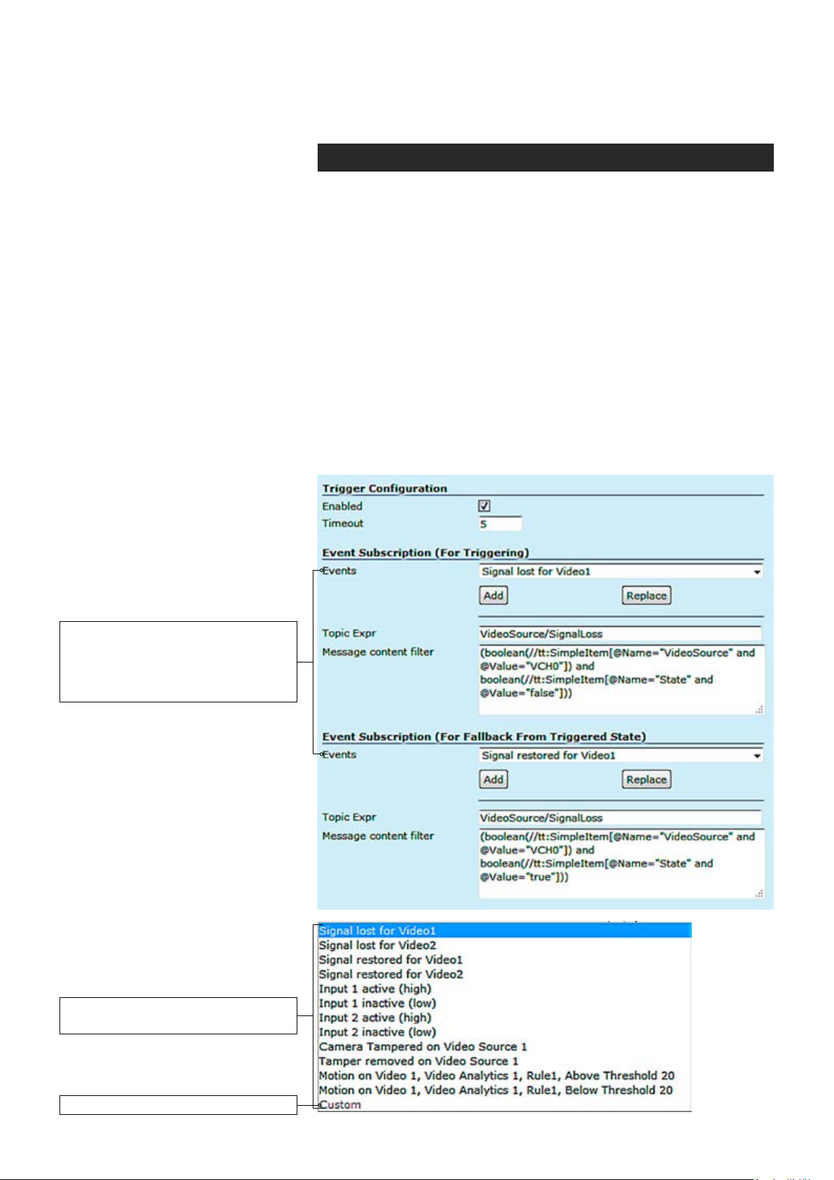
The event data is available in the “Message Content lter” box, which is
XPath format for matching XML content. Triggering occurs when dened
“Topic expression” and “message content lter” matches the internal event.
MPH encoder can trigger actions for video, audio (only MPH200 series)
and contact closers (Digital I/O) output. These events are also avail-
able for video management system to trigger congurable alarms. You
can add multiple event at the same time and each one triggers action.
Available events for triggering. First
choose the required event from the list
and then click Add button to select the
event -> The event data appears on
the Message content lter box.
The list of available events
for triggering.
Custom = Modied event for triggering.
12 MPH200 series video encoders WebUI user manual
An example when the video bit rate
and frame rate change when an
event triggered.
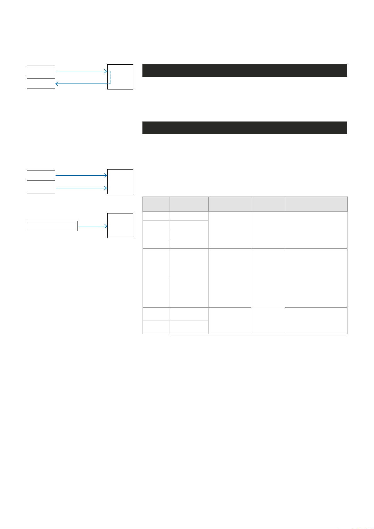
Event management for video
For video it can trigger actions such as changing video settings, frame
rate, bit rate and video quality for each video prole based on events.
Event subscription (for triggering)
Signal lost for video 1 and 2 Signal restored for video 1 and 2
Camera tempered for video source 1 and 2 Temper removed for video source 1 and 2
Motion detection above the threshold for
video 1 and 2
Event subscription (for fallback from
triggered state)
Motion Detection below the threshold for
video 1 and 2
Available events for video.
Event management for contact closure (digital I/O)
For contact closure it can trigger actions such as changing output state
in case of an event.
Event subscription (for triggering)
I/O Inputs activation I/O Inputs deactivation
Event subscription (for fallback from
triggered state)
Available events for contact closure.
13 MPH200 series video encoders WebUI user manual
Conguring video channels
Video connection
Note! MPH encoder has automatic
NTSC/PAL video format detection.
When changing the video format, the
device must reboot.
1
2
VIDEO ENCODER CONFIGURATIONS
3
4
5
VIDEO INTERFACES
(Physical video input)
VIDEO SOURCE CONFIGURATIONS
(Video overlay settings)
(6 encoding combinations)
MEDIA PROFILE CONFIGURATIONS
(up to 12 media profiles)
MAIN PAGE
(Start / Stop video streaming)
Step-by-step owchart how to congure
video channel in the MPH encoder.
MPH encoder is available in one and two video input models. One
channel model has support for
channel model has support only for
CVBS or HD-SDI video signal,
CVBS video signal.
One channel
two
(CVBS input) model has equipped with additional loop-though output
connector. The video connector type is a BNC female. The video input
impedance is 75 Ω. The nominal input level is 1 Vpp. Video inputs are
equipped with dual colour VIDEO indicator led’s on the front panel.
Video port settings can be congured from web user interface (WebUI).
Led Colour Video mode
Green
(Short)
Video 1
Led Colour Video mode
Video 2
Blinking
Green
Orange
Off / Dark Power is OFF or device is restarting.
Green
(Short)
Blinking
Green
Orange
Off / Dark
Video connector is used as video input and is locked
to valid video signal
The video input is not used in any active media
prole, but is locked to video
Video connector is used as video input, but no valid
video signal is detected
Video connector is used as video input and is locked
to valid video signal
The video input is not used in any active media
prole, but is locked to video
Video connector is used as video input, but no valid
video signal is detected
Power is OFF or device is restarting, or congured
for loop-through output (1-ch version only)
Video channel conguration
MPH is an ONVIF compliant encoder and video channel conguration is
designed according to ONVIF standard.
Note! Before modifying the conguration of a video prole, make
sure that video stream is stopped on the MAIN page (changing
only encoding parameters don’t require stopping of the stream).
14 MPH200 series video encoders WebUI user manual
Camera
Monitor
CVBS
loop-through
MPH241 contains one video input
(with loop-through).
Note! One channel MPH encoder’s
second video connector is loopthrough port for an analog monitor.
It is designed to transmit the same
analog video signal out that is
received from video input.
Camera 1
Camera 2
CVBS
CVBS
MPH
MPH
Video streaming methods
Video input is the physical video connector (BCN female) available for
video signal. Naturally each video input can be connected to a camera or
any other standard video source. The default video input mode is set to
PAL/NTSC format (CVBS). MPH241 model has also support fot HD-SDI.
High-denition serial digital interface (HD-SDI)
MPH241 encoder supports HD-SDI digital video interface. HD-SDI inter-
face is dened by SMPTE 292M standard and allows bitrates up to 1.485
Gbit/s. Progressive input signals are recommended to provide the best
picture quality. The HD-SDI support can be enabled with MLH213 license.
When changing the video format from CVBS to HD-SDI, the device must
reboot. The loop-through port is not available in HD-SDI mode.
MPH242 contains two video inputs.
HD video camera
HD-SDI
MPH
MPH241 encoder supports HD-SDI digital video format up to 1080p resolution
(when license MLH213 enabled) .
Input
Signal
720p25 1...25fps
720p30
720p60
1080i50 1...25fps
1080i60 1...30fps
1080p25 1...25fps
1080p30 1...30fps
Output frame/
eld rates
1...30fps720p50
Resolutions Coding Notes
1280x720,
QCIF, CIF, 4CIF
1920x1080),
QCIF, CIF, 4CIF
1920x1080),
QCIF, CIF, 4CIF
Progressive
Field coded
Progressive
Supported HD signal formats and encoding formats.
Input signal is progressive, thus deinterlace is
not needed neither at
encoder or decoder side
Input signal 1080i is
interlaced format
containing 60 elds/s.
Transmitted video
stream is interlaced
(eld-coded), thus
deinterlacing at decoder
side is required when
display is progressive
Input signal is progressive, thus deinterlace is
not needed neither at
encoder or decoder side
15 MPH200 series video encoders WebUI user manual
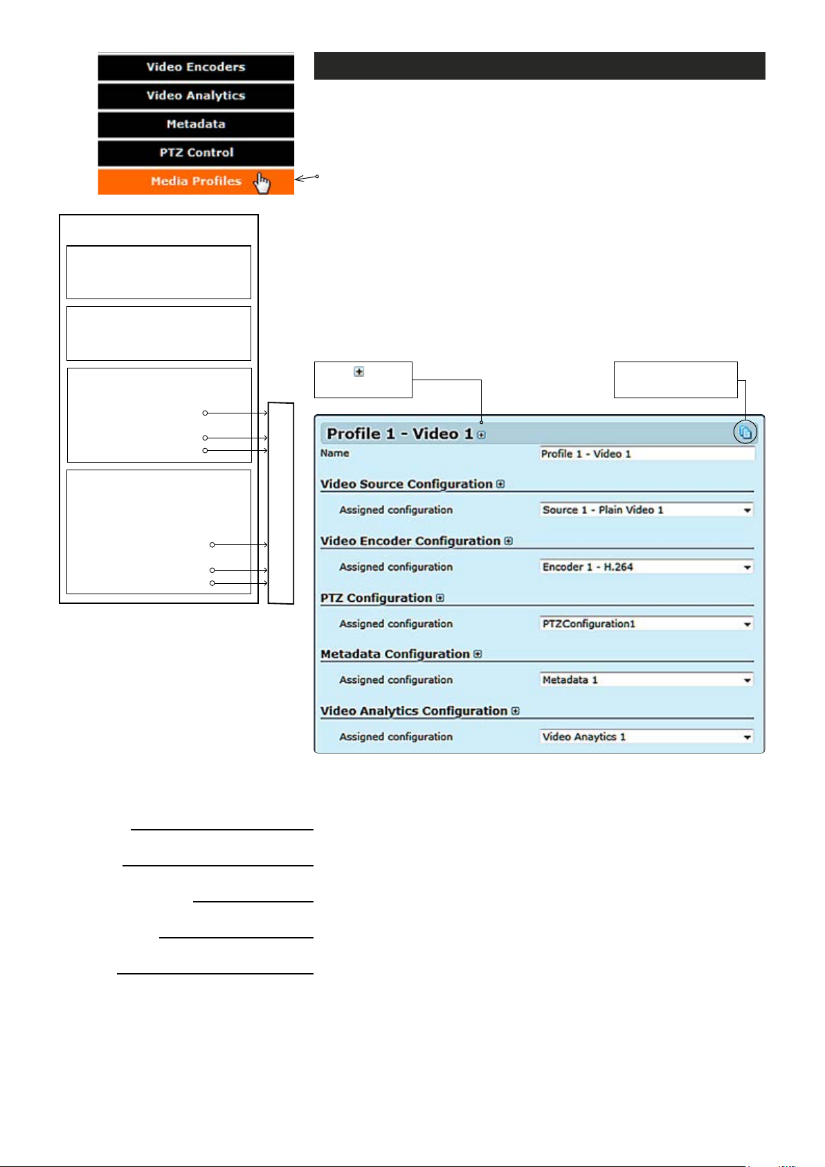
MEDIA PROFILE
Media prole (video)
MPH series encoders has a total of six (6) media proles. Each media
prole can be set separately for individual resolution, frame rate, GOP
structure and bitrate, within the processing power of the device.
Click “Media Proles” under the Media Conguration menu. Media
Prole Congurations page appears on the screen. On this page you
can associate virtual video sources with physical video inputs and
encoding proles.
VIDEO INTERFACE
•
Brightness, contrast & saturation
•
Privacy zone masking
VIDEO SOURCE CONFIGURATION
•
Physical video interface selection
•
Text overlay
ENCODER CONFIGURATION
•
Destination IP address
- primary stream
•
Additional IP address(es)
- stream multiplication
•
Dynamic streams (RTSP)
• Events
• Analytics (Motion detection,
tampering detection
• Destination IP address
- primary stream
• Additional IP address(es)
- stream multiplication
• Dynamic streams (RTSP)
METADATA
Description how the video encoder,
a video source and video input is
assembled to the media prole.
Click to see
more settings.
Streams output (RTP)
By default this page contains six different media proles.
Notes! It is not possible to change encoding format /resolution
and video input settings on this page. Before modifying the proles
the video stream must be stopped on the MAIN page.
Click this to create
copy from prole.
MEDIA PROFILE CONFIGURATIONS page.
Name:
Video Source Conguration
Assigned conguration:
Video Encoder Conguration
Assigned conguration:
PTZ Conguration
Assigned conguration:
Metadata Conguration
Assigned conguration:
Video Analytics Conguration
Assigned conguration:
16 MPH200 series video encoders WebUI user manual
User dened alias name for
_________________________________________________________
Select assigned video source conguration.
_________________________________________________________
Select assigned video encoder conguration.
_________________________________________________________
Select assigned PTZ conguration.
_________________________________________________________
Select assigned metadata conguration.
_________________________________________________________
Select assigned video analytics conguration.
media prole (max 63 chars).
Video status. The colour bar reect
the status of the video. Green colour
bar means that there is video signal.
Yellow colour bar with text tells that
there is no video.
Screenshot from the current video.
Indicates what media prole is using
this video interface.
When monitoring an area for security,
there may be certain parts within the
camera’s eld of view that need to be
kept private. Masking is a feature that
enables these areas to be concealed
from view.
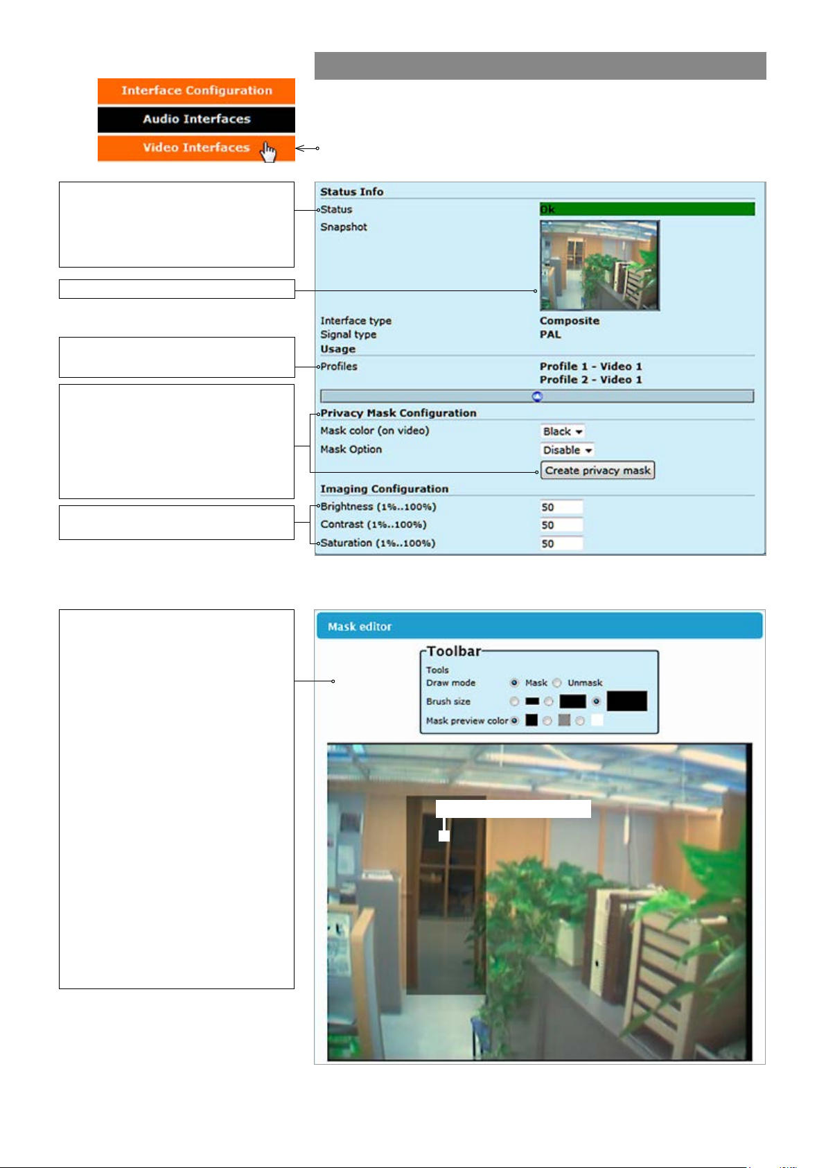
Video interfaces
Click “Video Interfaces” under the Interface Conguration menu. Video
Interfaces page appears on the screen. In this page you can see the
number of physical video inputs available and adjust the brightness,
contrast and saturation values for them.
Brightness, Contrast and Saturation
values for the video channel.
User can congure the encoder to
automatically hide certain areas with
a mask, which can be adjusted in
terms of its colour
Mask editor shows a screenshot from
camera view and overlays a
translucent mask on the image.
.
Draw mode: Masked (highlighted)
areas are private areas that are
removed (concealed) from
camera’s view.
Brush size: Select brush size
for masking.
Mask color: Depending on the
brightness of the image snapshot,
appropriate mask preview color can
be chosen. This color affects the
preview on mask editor only and
doesn’t reect on the streaming video.
VIDEO INTERFACES page.
Masked/Highlighted area
MASK EDITOR page contains settings for hiding certain areas from the
encoded picture.
17 MPH200 series video encoders WebUI user manual
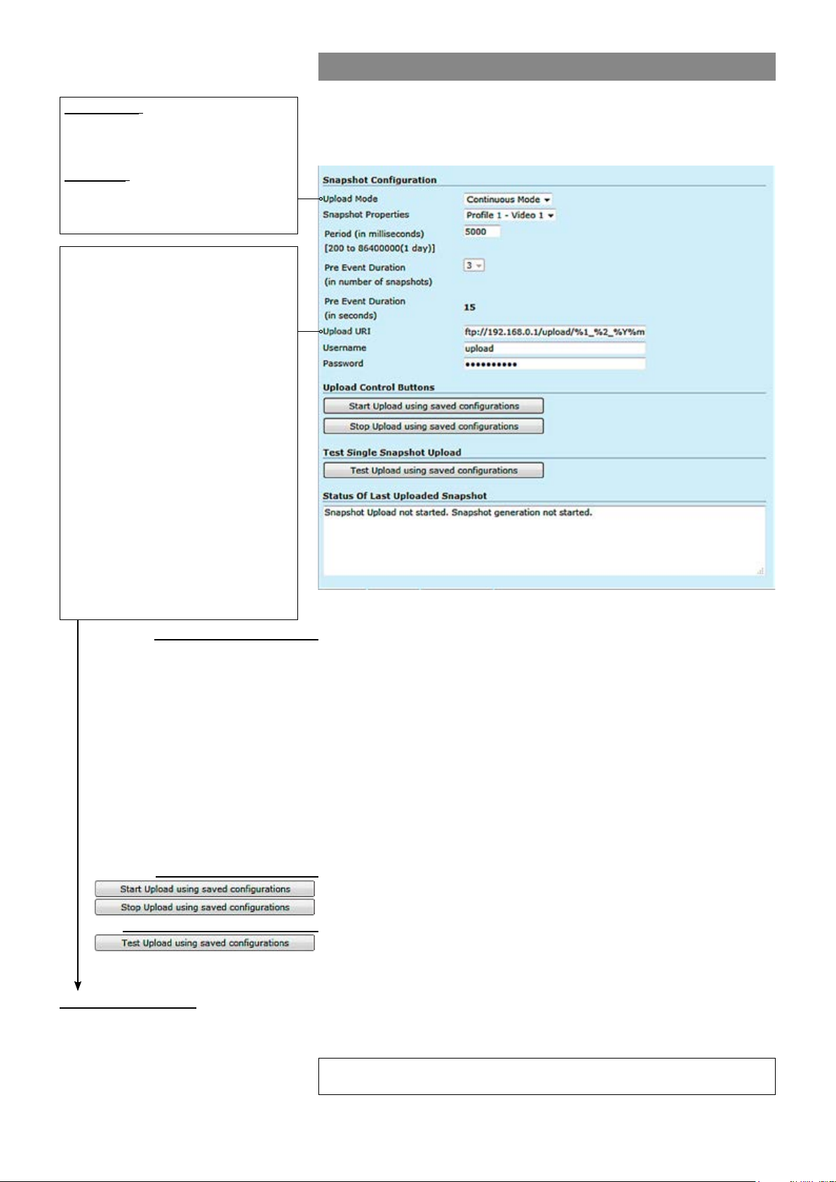
JPEG snapshot conguration
Continuous: Device generates a
snapsthot at specied interval (period)
and sends the images to congured
Additionally there is a JPEG image capture feature that allows taking
JPEG snapshots from the video and storing them into a ftp server. It is
also possible view JPEG captures with http.
FTP server.
Triggered: Snapshots are generated
when internal event triggers it. Triggering event can be motion detection,
tampering or digital IO event.
%d: The day of the month as a decimal
number (range 01...31).
%H: The hour as a decimal number using a
24-hour clock (range 00...23).
%I: The hour as a decimal number using a
12-hour clock (range 01...12).
%m: The month as a decimal number
(range 01...12).
%M: The minute as a decimal number
(range 00...59).
%S: The second as a decimal number
(range 00...60).
%4: The milliseconds as a decimal number
(range 0000...9999).
%p: Either “AM” or “PM” according to the
given time value, or the corresponding
strings for the current locale. Noon is
treated as “PM” and midnight as “AM”.
%y: The year as a decimal number without
a century (range 00...99).
%Y: The year as a decimal number
including the century.
%1: Device hostname (manually conf. or
received from DHCP-server).
Snapshot Conguration:
Upload Mode:
_________________________________________________________
Snapshot generation can operate in two separate modes: Continous
and triggered mode.
Snapshot Properties:
Period (in milliseconds):
Pre Event Duration:
Keeps the event state unchanged for the dened period for instance if an
Specied interval when device generates a snapsthot.
After event has occured, device sends rst congured number of images
before the event and then continues sending images until dened timeout
[ms] elapses.
Upload URI:
Denes the remote FTP server address. URI can contain arbitrary
directory path and device shall create the directory if it does not yet exist.
Username:
Password:
Set username for server.
Set password for server.
Note! Hard Factory reset restores admin password to defaults.
Upload Control Buttons:
_________________________________________________________
Starts uploading using saved congurations.
:
Stops uploading using saved congurations.
Test single Snapshot Upload:
Status of last Uploaded Snapshot:
_________________________________________________________
Tests upload using saved congurations.
:
_________________________________________________________
Shows status of last uploaded snapshots.
Snapshot URI example:
ftp://192.168.0.247/upload/%1_%Y%m%d/camera1_%H%M%S_%4.jpg expands to:
ftp://192.168.0.247/upload/MPH102-RD00101126_20140424/camera1_183059”)_830.jpg
Trigger Conguration
See section “Event management system” from page 31 for more details.
18 MPH200 series video encoders WebUI user manual

Video source and sinks
Click “Video Source and Sinks” under the Media Conguration menu.
Video Source Congurations page appears on the screen. Video
overlay settings can be changed on this page, you can enter a text and
time/date on the video.
Note! Date and time settings can be changed from Date & Time page.
There are four different virtual video sources available for video inputs.
This feature allows you to set four different views with/without video
overlay content.
VIDEO SOURCE CONFIGURATIONS page.
19 MPH200 series video encoders WebUI user manual
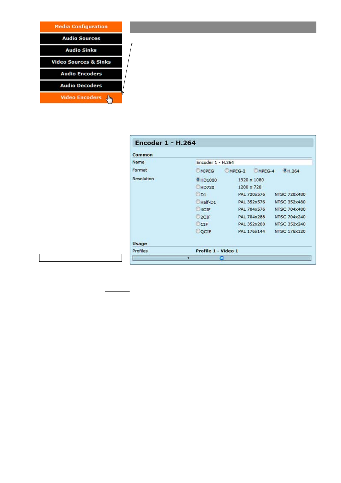
Video encoders
Click “Video Encoders” under the Media Conguration menu. Video
Encoder Congurations page appears on the screen. Video encoding
settings can be congured on this page, e.g. select format (MJPEG,
MPEG-2, MPEG-4 and H.264), set resolution, bit rate, frame rate and
multicast IP/port settings for each prole.
This page contains (by default) six different customizable encoding
proles. This feature allows you to set six different video encoding
combinations, each with their own settings.
On this page you can also add multiplied multicast/unicast streams from
each encoder.
Click this to see more settings.
Common
Name:
Resolution:
VIDEO ENCODER CONFIGURATIONS page.
_________________________________________________________
User dened alias name for
Video resolution, either digital HD1080 or HD720, or analog D1, Half-
D1, 4CIF, 2CIF, CIF or QCIF.
video prole (max 63 chars).
20 MPH200 series video encoders WebUI user manual
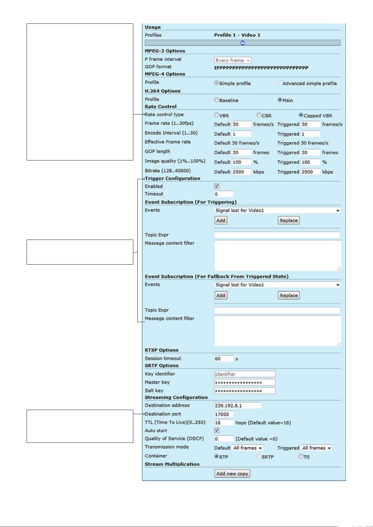
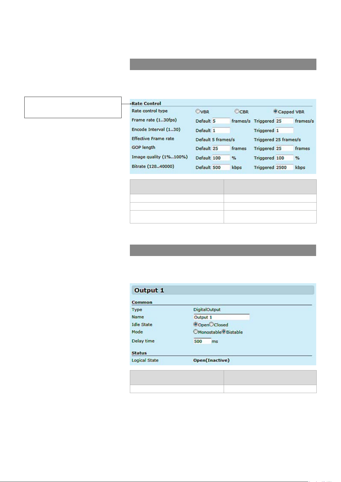
VBR (Variable Bit Rate) video aims at
constant quality, but as the bit rate
uctuates over time.
CBR (Constant Bit Rate) video
uctuates in quality, while its multiplexing behaviour is easy to predict.
Because in unconstrained VBR video
the bit rate uctuation might be too
large, capped VBR video is proposed
as an alternative. Capped VBR video
aims at a constant quality, but when in
certain intervals this requires a too
high bit rate, the bit rate is limited
(i.e.,capped) in order to support more
video ows on the links, at the
expense of a quality reduction.
Trigger Conguration
See section “Event management
system” from page 60 for more details.
Note! Only even port numbers can
be used for RTP, and then the
following odd port number shall be
used for RTCP (RFC 1889).
VIDEO ENCODER CONFIGURATIONS page.
21 MPH200 series video encoders WebUI user manual

Usage
Proles:
MPEG-2 Options:
P frame interval:
GOP format:
MPEG-4 Options:
Simple prole:
Advanced simple prole:
H.264 options:
Baseline:
Main:
Rate control:
Rate control type:
Frame rate (1...30fps):
Encode Interval (1...30):
GOP length:
Image quality (1%...100%):
Bitrate (128...20000):
Trigger conguration:
Enabled:
Timeout:
Event subscription (for triggering):
Events:
Topic Expr:
Message content lter:
RTSP options:
Session timeout:
Streaming Conguration:
Destination address:
Destination port:
TTL (Time To Live):
Auto start:
_________________________________________________________
Here you see how the media prole is assigned to a video source.
_________________________________________________________
There are three options; Every frame = IP, Every second frame = IBP,
Every third frame = IBBP.
MPEG-2 GOP format.
_________________________________________________________
Simple Prole (SP) is recommended only for decoder compatibility.
Interlacing toolsets are not used.
Advanced Simple Prole (ASP) Level 5 enables Macroblock-Adaptive
Frame/Field Coding (MBAFF) which offers better image quality and
better compression ratio with interlaced video signal. Recommended
choice when interlaced stream is selected (D1 and Half-D1 resolutions).
_________________________________________________________
Baseline Prole (BP) Level 3 is recommended only for decoder compat-
ibility. Interlacing toolsets are not used.
Main Prole (MP) Level supports eld encoding which which offers
better image quality and better compression ratio with interlaced video
signal. Recommended choice when interlaced stream is selected (D1
and Half-D1 resolutions).
_________________________________________________________
Denes video bitrate mode. There are three options available, variable
bitrate (VBR), constant bitrate (CBR) or capped VBR. Rate control is a
trade off between quality uctuations and bit rate variability.
Denes video frame rate (adjustable 1...30fps for PAL/NTSC).
Denes encoding frame interval; for instance when encoding interval is 1,
all frames are encoded, value 2 means, every second frame is encoded.
Species the order in which intra- and inter-frames are arranged. The
GOP is a group of successive pictures within an encoded video stream.
Each coded video stream consists of successive GOPs. From the pic
tures contained in it, the visible frames are generated. For instance if you
25 FPS video stream, GOP= 25 means one I-frame per full frame.
GOP = 13 means two I-frames per full frame. GOP = 5 means 5 I-frames,
20 p-frames per second
Encoded video image quality, can adjust in VBR or capped VBR mode.
Encoded video bitrate, 128Kbps...15Mbps.
_________________________________________________________
Enables or disables the trigger feature.
Keeps the event state unchanged for the dened period for instance if an
event clears quickly, it does not change its state for the dened timeout,
recommended 5 seconds.
_________________________________________________________
Select the event type.
The topic expression of the event.
Event description, lter and values.
_________________________________________________________
Timeout for RTSP session
_________________________________________________________
Destination IP address. Multicast: Multicast IP address / multicast group.
This multicast IP address has to be same at both encoder and corresponding decoders. Unicast: IP address of receiving decoder.
UDP port number (0...65536). This number has to be same at both
encoder and decoder pairs. Use even port numbers only.
Time-To-Live for video packets = number of hops that a packet is permitted to travel before being discarded by a router
(0...255)
.
Video streaming will automatically start after reboot. Changing autostart
does not immediately start or stop streams.
22 MPH200 series video encoders WebUI user manual
Quality of Service (DSCP )(0...63):
Transmission mode:
Container:
Note! Only even port numbers can
be used for RTP, and then the
following odd port number shall be
used for RTCP (RFC 1889).
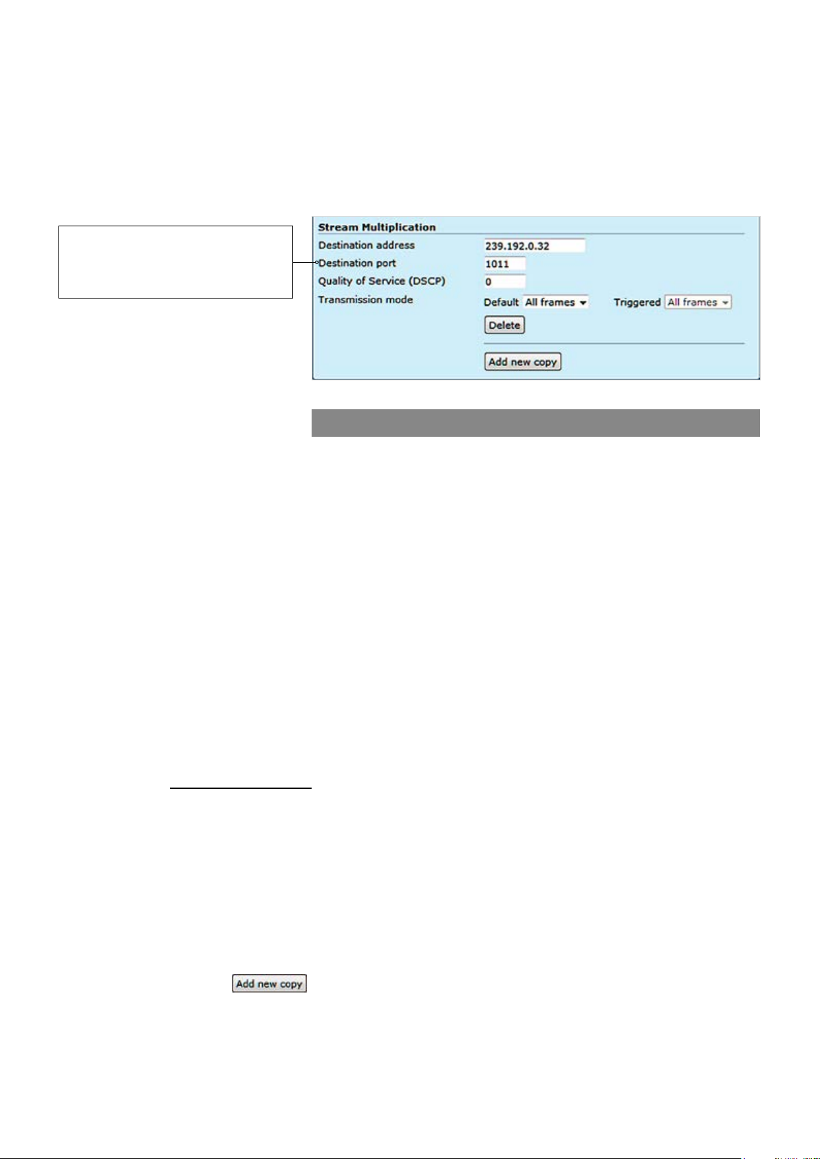
Stream multiplication:
Destination address:
Destination port:
Quality of Service (DSCP/DiffServ ):
Transmission mode:
(Differentiated Services Code Point) eld lets you set bits in the stream IP
header allowing a network device to apply rules such as how the packet is
forwarded in the network and QoS (Quality of service) management.
All frames is the default option and enables the encoder to pass (stream)
all frames (I and P frames). I frames enables encoder to send only
I-frames, meaning ltering all P frames. Paused = pause streaming.
RTP (Real-time Transport Protocol), SRTP (Secure Real-time Transport
Protocol) or TS (MPEG transport stream).
Video stream multiplication
Each video encoding prole can be assigned with ve (5) different destination addresses (primary stream and additional streams). These addresses
can be freely set to unicast, multicast or a combination of these. In addi-
tion there is a tick box that enables to lter out P-frames from each output
stream for low frame rate applications. This approach provides for a very
cost efcient dual streaming in situations where the low frame rate stream
is a direct subset of the higher frame rate stream. In practise this means
that the number of I-frames is the common nominator. As an example, one
MPH241 unit can stream (unicast or multicast) 2 x D1@25fps for monitoring and 4 x 2CIF@3fps (unicast or multicast) for recording simultaneously.
The precondition is, the number of I-frames per second in the primary
stream should match to frame rate of the low frame rate stream. In the
example above the I-frame interval of the primary stream would need to be
8 (GOP = IPPPPPPPIPPPPPPPIPP…) generating 3 I-frames per second
thus resulting in 3fps stream when P-frames are ltered out. The use of
multiple destination addresses up to a certain degree doesn’t load the
MPU; however one should take into account that the aggregate bit rate of
all output streams does not exceed the capacity of the 100Mbps interface.
_________________________________________________________
Destination IP address. Multicast: Multicast IP address / multicast group.
This multicast IP address has to be same at both encoder and
corresponding decoders. Unicast: IP address of receiving decoder.
UDP port number (0...65536). This number has to be same at both
encoder and decoder pairs. Use even port numbers only.
Differentiated Services Code Point eld lets you set bits in the stream IP
header allowing a network device to apply rules such as how the packet is
forwarded in the network and QoS (Quality of service) management.
All frames is the default option and enables the encoder to pass (stream)
all frames (I and P frames). I frames enables encoder to send only
I-frames, meaning ltering all P frames. Paused = pause streaming.
:
Adds new copy from stream.
23 MPH200 series video encoders WebUI user manual

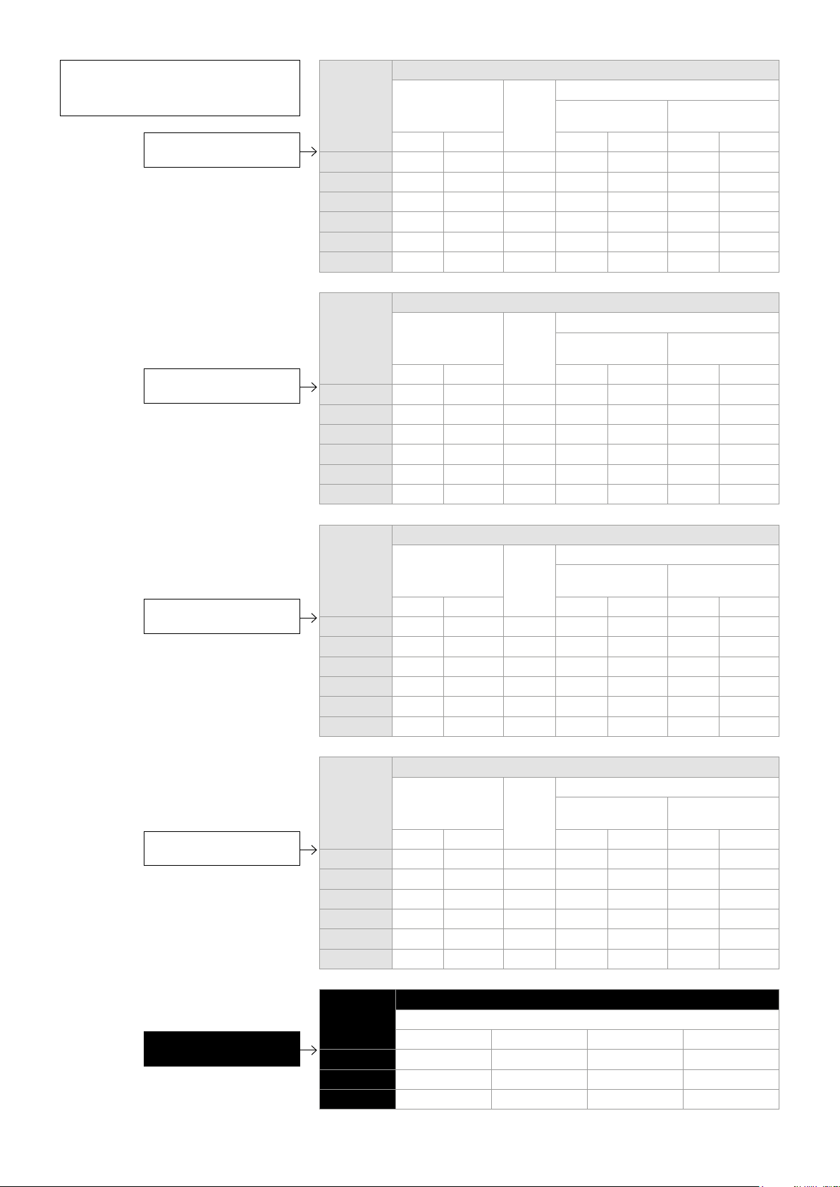
Video streaming performance
The following performance table shows the performance of MPH200
devices in encoding and streaming video signal per video input
simultaneously.
Total video sessions = original video stream + multiplied streams.
SRTP (Secure Real-time Transport Protocol) = encrypted RTP stream.
De-interlacing is done by choosing right prole.
Congurations for single input in two channel encoder (NTSC/PAL)
MPEG-2/
MPEG-4/H.264
Encoder 1
D1 30fps
6Mbps
D1 30fps
6Mbps
D1 30fps
6Mbps
CIF 30fps
1.5Mbps
MPEG-2/
MPEG-4/H.264
Encoder 1
D1 30fps
6Mpbs
1080p 30fps
20Mbps
MPEG-2/
MPEG-4/H.264
Encoder 2
4CIF 30fps
6Mbps
4CIF 15fps
6Mbps
2CIF 30fps
3Mbps
CIF 30fps
1.5Mbps
Congurations for single input in single channel encoder (NTSC/PAL)
MPEG-2/
MPEG-4/H.264
Encoder 2
D1 30fps
6Mpbs
MPEG-2/
MPEG-4/H.264
Encoder 3
CIF 30fps
1.5Mbps
MPEG-2/
MPEG-4/H.264
Encoder 3
4CIF 30fps
6Mbps
MPEG-2/
MPEG-4/H.264
Encoder 4
CIF 30fps
1.5Mbps
MPEG-2/
MPEG-4/H.264
Encoder 4
4CIF 30fps
6Mbps
Privacy
zone
De-
masking
interlace
30 fps Yes
15 fps Yes
Yes
Yes
Privacy
zone
De-
masking
interlace
30fps Yes
Yes
Motion
detection
QCIF
5fps
QCIF
5fps
QCIF
5fps
Motion
detection
QCIF
5fps
QCIF
5fps
Tampering
Yes
Yes
Yes
Tampering
Yes
Yes
Text
overlay
40 chars/
encoder
40 chars/
encoder
40 chars/
encoder
40 chars/
encoder
Text
overlay
40 chars/
encoder
40 chars/
encoder
Total
sessions
3 3
3 3
3 3
4 4
Total
sessions
8 4
2 1
SRTP
sessions
SRTP
sessions
Audio
1xAAC
stereo
1xAAC
stereo
1xAAC
stereo
1xAAC
stereo
Audio
1xAAC
stereo
stereo
1xAAC
720p 30fps
10Mbps
Yes
QCIF
5fps
Yes
40 chars/
encoder
4 2
1xAAC
Available video streaming performance for MPH200 series encoders.
Note! Video trafc could overload Fast Ethernet throughput
depending on number of streams/bitrate combination. Be sure that
the conguration does not exceed Fast Ethernet port throughput.
24 MPH200 series video encoders WebUI user manual
stereo
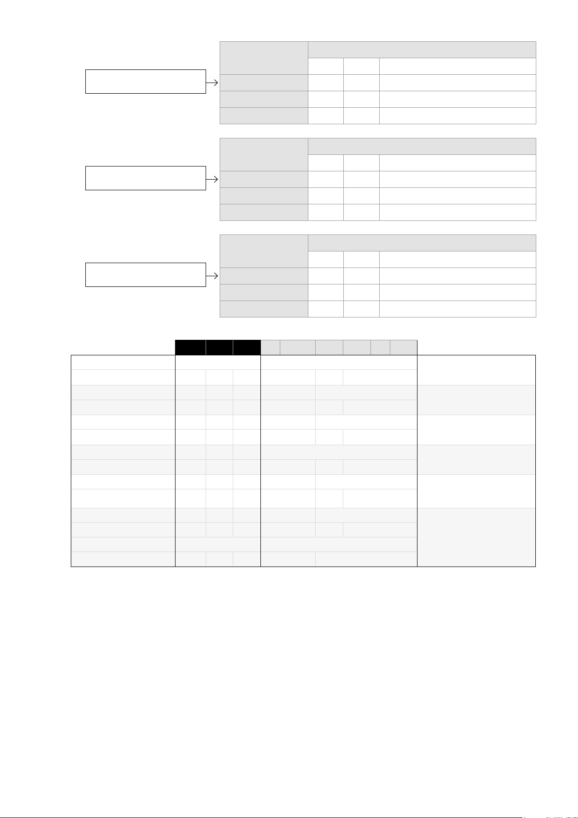
*Note! Minimum (Min) values may
be smaller without any picture
quality degradation.
Recommended bitrates
for H.264 encoding.
Recommended bitrates
for MPEG-4 encoding.
Resolution Bitrate (kbps)
Min* Max Recommended
Interlacing
toolsets OFF
CBR CapVBR CBR CapVBR CBR CapVBR
D1 1900 1900 5500 2500 2500 2800 2300
4CIF 1900 1900 5500 2500 2500 2800 2300
Half D1 1000 1000 3000 1400 1400 1700 1300
2CIF 1000 1000 3000 1400 1400
CIF 500 500 1700 650 650
QCIF 150 150 500 200 200
Resolution Bitrate (kbps)
Min* Max Recommended
Interlacing
toolsets OFF
CBR CapVBR CBR CapVBR CBR CapVBR
D1 2200 2200 6000 3500 3500 3200 3200
4CIF 2200 2200 6000 3500 3500 3200 3200
Half D1 1200 1200 3200 1900 1900 1800 1800
2CIF 1200 1200 3200 1900 1900
CIF 600 600 2000 1000 1000
QCIF 200 200 600 300 300
Interlacing
toolsets ON
Interlacing
toolsets ON
Recommended bitrates
for MJPEG encoding.
Recommended bitrates
for MPEG-2 encoding.
Resolution Bitrate (kbps)
Min* Max Recommended
Interlacing
toolsets OFF
CBR CapVBR CBR CapVBR CBR CapVBR
D1 6000 6000 12000 8000 8000 8000 8000
4CIF 6000 6000 12000 8000 8000 8000 8000
Half D1 3000 3000 6000 4500 4500 4500 4500
2CIF 3000 3000 6000 4500 4500
CIF 2000 2000 4500 2500 2500
QCIF 600 600 1300 750 750
Resolution Bitrate (kbps)
Min* Max Recommended
Interlacing
toolsets OFF
CBR CapVBR CBR CapVBR CBR CapVBR
D1 2500 2500 6600 4600 4600 4200 4200
4CIF 2500 2500 6600 4600 4600 4200 4200
Half D1 1300 1300 3500 2500 2500 2300 2300
2CIF 1300 1300 3500 2500 2500
CIF 700 700 2500 1300 1300
QCIF 200 200 600 350 350
Interlacing
toolsets ON
Interlacing
toolsets ON
Resolution Bitrate (Mbps)
Recommended
Recommended bitrates
for HD video encoding.
25 MPH200 series video encoders WebUI user manual
720p 4...5 4.6...5.8 8...10 12.6...15.8
1080i60 10...12 11.5...13.8 21...24 31.5...37.8
1080p30 10...12 11.5...13.8 21...24 31.5...37.8
H.264 MPEG-4 MPEG-2 MJPEG
Recommended GOP sizes
for H.264 encoding.
Recommended GOP sizes
for MPEG-4 encoding.
Recommended GOP sizes
for MPEG-2 encoding.
Rate Control Mode GOP
Min Max Recommended
CBR 7 3000 60 -->
Capped VBR 7 3000 15 -->
VBR 7 3000 7 -->
Rate Control Mode GOP
Min Max Recommended
CBR 7 120 60...120
Capped VBR 7 120 15...120
VBR 7 120 7...120
Rate Control Mode GOP
Min Max Recommended
CBR 7 120 60...120
Capped VBR 7 120 15...120
VBR 7 120 7...120
Field Encoding
Deinterlacer
Field Encoding
Deinterlacer
Field Encoding
Deinterlacer
MBAFF
Deinterlacer
MBAFF
Field Encoding
Deinterlacer
Type eld value
Type specic eld values
1080p 1080i 720p D1 Half D1 4 CIF 2 CIF CIF QCIF
Not available Not available
x One eld used
na x na x Not available
x One eld used
x x
x One eld used
x One eld used
x x
x One eld used
x x
x One eld used
0 0
0 1 & 2 0 1 & 2 0
Supported interlace coding tools for the MPH video encoders.
H.264 Base Prole (BP)
Level 3
H.264 Main Prole (MP)
Level 3
MPEG-2 Main Prole (MP)
Main Level
MPEG-4 Simple Prole (SP)
Level 5
MPEG-4 Advanced Simple
Prole (ASP)
Level 5Deinterlacer
MJPEG
26 MPH200 series video encoders WebUI user manual
 Loading...