

Page 1
User manual – MPH241/242
MPH series video encoders
H.264 / MPEG-4 / MJPEG / MPEG-2 video encoders
for PTZ and fixed camera networking applications
MPH241 – 1-ch stand-alone video encoder
MPH242 – 2-ch stand-alone video encoder
SD, HD-SDI (1080p)
MPH200 series video encoders user manual, 59300463, rev002
Page 2

Contents
MPH series video encoders introduction ............................................................................................................... 1
MPH series video encoders front and rear panel ............................................................................................... 2-3
Getting started .......................................................................................................................................................... 4
Quick instructions ............................................................................................................................................... 4
Device’s IP address ............................................................................................................................................ 4
MPH200 series models ............................................................................................................................................. 5
Ethernet interface ..................................................................................................................................................6-7
Local ports, electrical interfaces ........................................................................................................................ 6
Power over Ethernet (PoE+) option .................................................................................................................... 6
Up-link ports, optical interfaces (SFP) ............................................................................................................... 6
How to unplug or plug-in the SFP transceiver module ...................................................................................... 7
To unplug and plug-in the SFP module, follow these steps ............................................................................... 7
Some generic notes for successful optical connections: ................................................................................... 7
Management interface .............................................................................................................................................. 8
General .............................................................................................................................................................. 8
WebUI ................................................................................................................................................................ 8
ONVIF ................................................................................................................................................................8
CLI – command line interface ............................................................................................................................ 8
Web user interface (WebUI) ................................................................................................................................ 9-11
General .............................................................................................................................................................. 9
System requirements for WebUI ........................................................................................................................ 9
Operation ........................................................................................................................................................... 9
Starting WebUI session ................................................................................................................................... 10
User levels and permissions ............................................................................................................................ 10
MA IN PAGE ..................................................................................................................................................... 11
Event management system ............................................................................................................................... 12-13
MPH event management system ..................................................................................................................... 12
Event management for video ........................................................................................................................... 13
Event management for contact closure (digital I/O) ......................................................................................... 13
Conguring video channels ..............................................................................................................................14 -24
Video connection ............................................................................................................................................. 14
Video channel conguration ............................................................................................................................. 14
Video streaming methods ................................................................................................................................ 15
High-denition serial digital interface (HD-SDI) ............................................................................................... 15
Media prole (video) ......................................................................................................................................... 16
Video interfaces .............................................................................................................................................. 17
JPEG snapshot conguration .......................................................................................................................... 18
Video source and sinks ................................................................................................................................... 19
Video encoders ............................................................................................................................................... 20
Video stream multiplication .............................................................................................................................. 23
Video streaming performance .......................................................................................................................... 24
Conguring audio channels .............................................................................................................................2 7- 34
Conguring data channels ................................................................................................................................35-39
Conguring contact closure channels ........................................................................................................... 40-42
Event management ........................................................................................................................................... 43-44
Video analytics congurations ............................................................................................................................ 45
Metadata congurations ........................................................................................................................................ 46
Network settings ................................................................................................................................................ 47-4 8
Date & time settings ...............................................................................................................................................49
Device management ...............................................................................................................................................50
Services settings ............................................................................................................................................... 51- 53
User management ................................................................................................................................................... 54
Conguring ethernet switch ............................................................................................................................. 55 -74
Command line interface - CLI ...........................................................................................................................75 - 87
MPH200 specications ........................................................................................................................................... 89
Legal declarations .................................................................................................................................................. 90
Page 3

MPH series video encoders introduction
Stand-alone video encoder with 1 or 2 video inputs, bi-direc-
tional data, audio & contact closure channels + Ethernet switch
General
MPH series encoders are ONVIF (Open Network Video Interface Forum)
compliant products. This provides wide interoperability with any ONVIF
compliant device or system.
Many similarities exist between the MPH series video encoders; the main
difference being the number of video channels available and the mechanics. MPH series video encoders are high performance video processing
products encoding real time video in mission critical applications for
customers in Transportation, City Center Monitoring, and Corporate
Security. MPH200 series encoders are temperature-hardened compact
size stand-alone video processing products in the MPX platform.
MPH200 series video encoders provides in addition to transparent link
of CVBS or HD-SDI video signal up to 1080p resolution (SMTP292M),
independently congurable general-purpose bi-directional asynchronous
data, bi-directional audio channels and bi-directional contact closure
channels. Additionally a layer 2 manageable Ethernet switch is integrated into the encoder. The Ethernet switch comes with four gigabit
ports and full-feature layer 2 switching functions such as RSTP, IGMP,
QoS and VLAN.
The encoded signal from MPH series encoder can be decoded with MPC/
MPX (except H.264) or VMX series HW and/or SW, as well as with industry
standard SW players such as Quicktime and VLC. The transmission is
accomplished over 10/100/1000BASE-T or 100BASE-FX (SFP) or
1000BASE-X (SFP) network utilizing IP/Ethernet streaming.
MPH series video encoders are equipped with the H.264, MPEG-4,
MJPEG and MPEG-2 video encoding engine. The default encoding
combination is H.264, MPEG-4 and MJPEG. MPEG-2 is an add-on
option, and it should be ordered separately.
The H.264 video encoding engine is compliant with the ISO/IEC 14496-10
(H.264@MP, BP, CBP) standard. The MPEG-4 video encoding engine is
compliant with the ISO/IEC14496-2 (MPEG-4@SP/ASP L5) simple prole
standard. The MJPEG video encoding engine is compliant with the ISO/
IEC 13818-2 (RFC 2435) standard. The MPEG-2 video encoding engine is
compliant with the ISO/IEC13818 (MPEG-2 MP@ML) standard.
Note! This product is under
development and Teleste
reserves the rights to alter
specications, features,
manufacturing release dates and
even the general availability of
the product at any time.
1 MPH200 series video encoders user manual
General-purpose asynchronous data channels are transferred separately from the encoded video signals.
Firmware version
The functionality and operation of the devices described in this manual
applies for rmware version 6.0.x.
Page 4
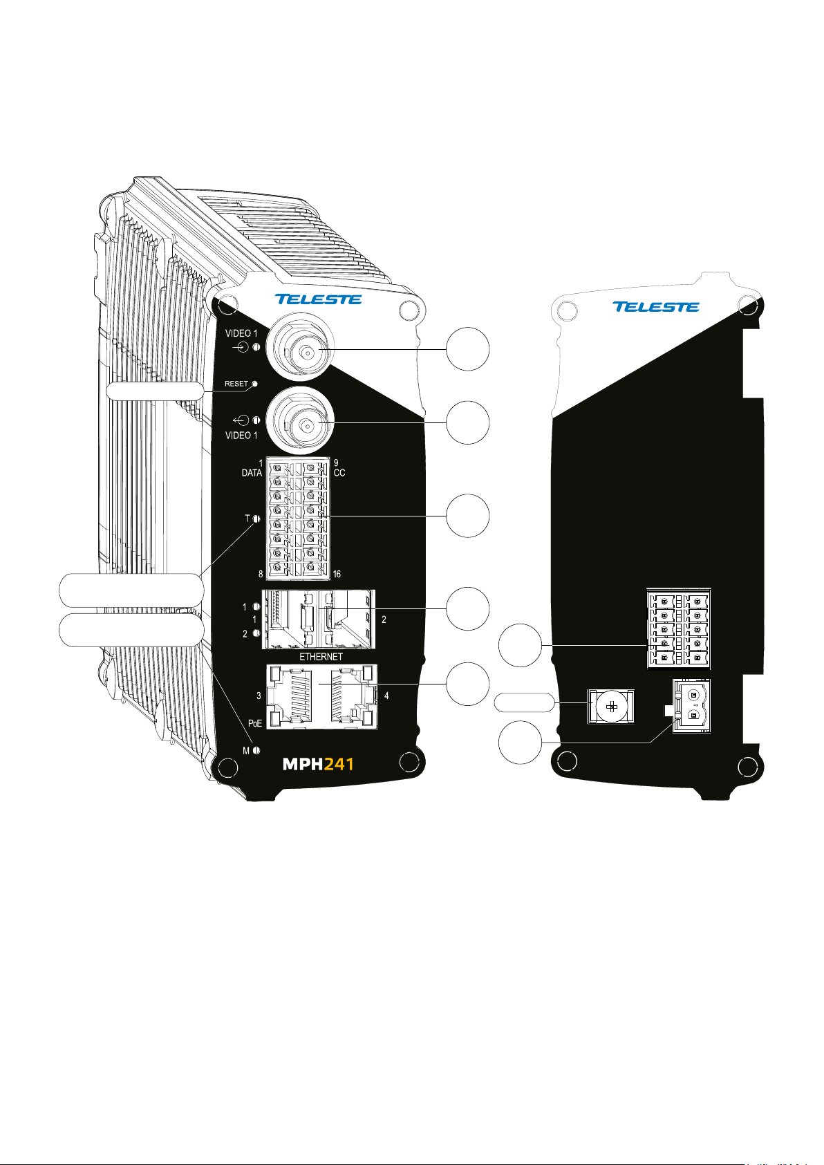
MPH series video encoders front and rear panel
Front panel Back panel
MPH200 stand-alone encoder (example view from MPH241 device)
1
Reset button
2
T - Led. Terminal
server indicator led
M - Led. Power and
status indicator led
3
4
5
6
Ground
7
GND
AUDIO
1
5 10
12...24 VDC
6
_
+
2 MPH200 series video encoders WebUI user manual
Page 5
CVBS
V
CVBS or
HD-SDI
x1
D
x2
A
x2
C
C
x2
E
x4
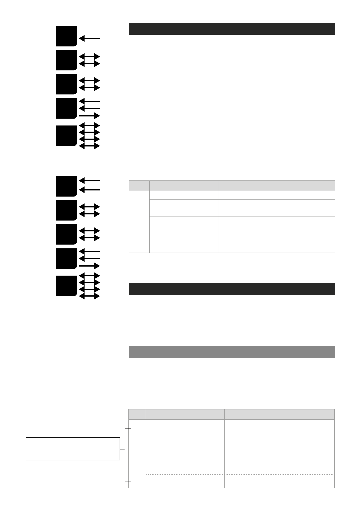
MPH241 signals.
MPH200 series video encoders mechanical connections
1. CVBS video input 1, or optional HD-SDI video input (BNC female) and
indicator led.
2. CVBS video input 2
Video loop through port for 1-ch versions and indicator led.
3. 16-pin screw terminal block and T indicator led:
Data interfaces, EIA RS422/485 (data1), EIA RS232 (data 2) /management interface (CLI) or general purpose serial port.
Contact closure interfaces (cc input 1, cc input 2, cc output)
4. Ethernet switch up-link interfaces, 2 x socket for SFP module (GE,
see a product catalogue for supported models).
5. Ethernet switch local port interfaces, 2 x 10/100/1000Base-T, RJ-45.
6. Audio interface (10-pin screw terminal block).
7. Power supply connector (2-pin screw terminal block, +12...28 VDC).
Reset button: Device software reboot and hard/soft factory defaults
restoration (see section Factory reset).
Ground: Device ground connection.
(BNC female)
for 2-ch versions or
V
x2
D
x2
A
x2
C
C
x2
E
x4
MPH242 signals.
Led Colour Mode
OFF / Dark Power off
Yellow Device starts up
Red Device self-test failed
M
M - (module/power led) LED indicator operation. This LED indicates power
status, factory reset, interface activity.
Factory reset
The factory reset can be done via WebUI, CLI, or using the pinhole reset
button on the front panel of device. There are two types of factory resets;
Soft factory and Hard factory reset. The Soft factory reset restores all,
except IP conguration to the default factory settings. The Hard factory
reset restores all settings to default factory settings.
Reset button
Green Power on / Device is functional
Device is being accessed from any interface.
Blinking Green
Whenever device is accesed from WebUI, CLI or ONVIF
interface, led blinks 2s. During software update, LED will
blink throughout the rmware image transfer duration.
The reset pinhole is a button that resets the device to its original default
settings. To use this button, insert a stiff wire (such as a straightened paper
Note! If pinhole button is not
released within time window,
operation will cancelled.
3 MPH200 series video encoders WebUI user manual
clip) into the pinhole. If you release the button immediately the device will
reboot with current settings. But if you hold the button you can restore the
default settings as following table shows.
Led Colour Mode
6 x (short) green blinks at
boot time
2 x (short) red blinks
M
24 x yellow blinks at boot time
(after the 6 green blinks)
4 x (short) red blinks
Time window to select Soft factory reset.
If reset button is released in this time window, soft factory
reset is selected.
Soft factory reset shall be applied.
Wait until device has fully started (power led green).
Time window to select Hard factory reset.
If reset button is released in this time window, hard
factory reset is selected.
Hard factory reset shall be applied.
Wait until device has fully started (power led green).
Page 6
Getting started
Quick instructions
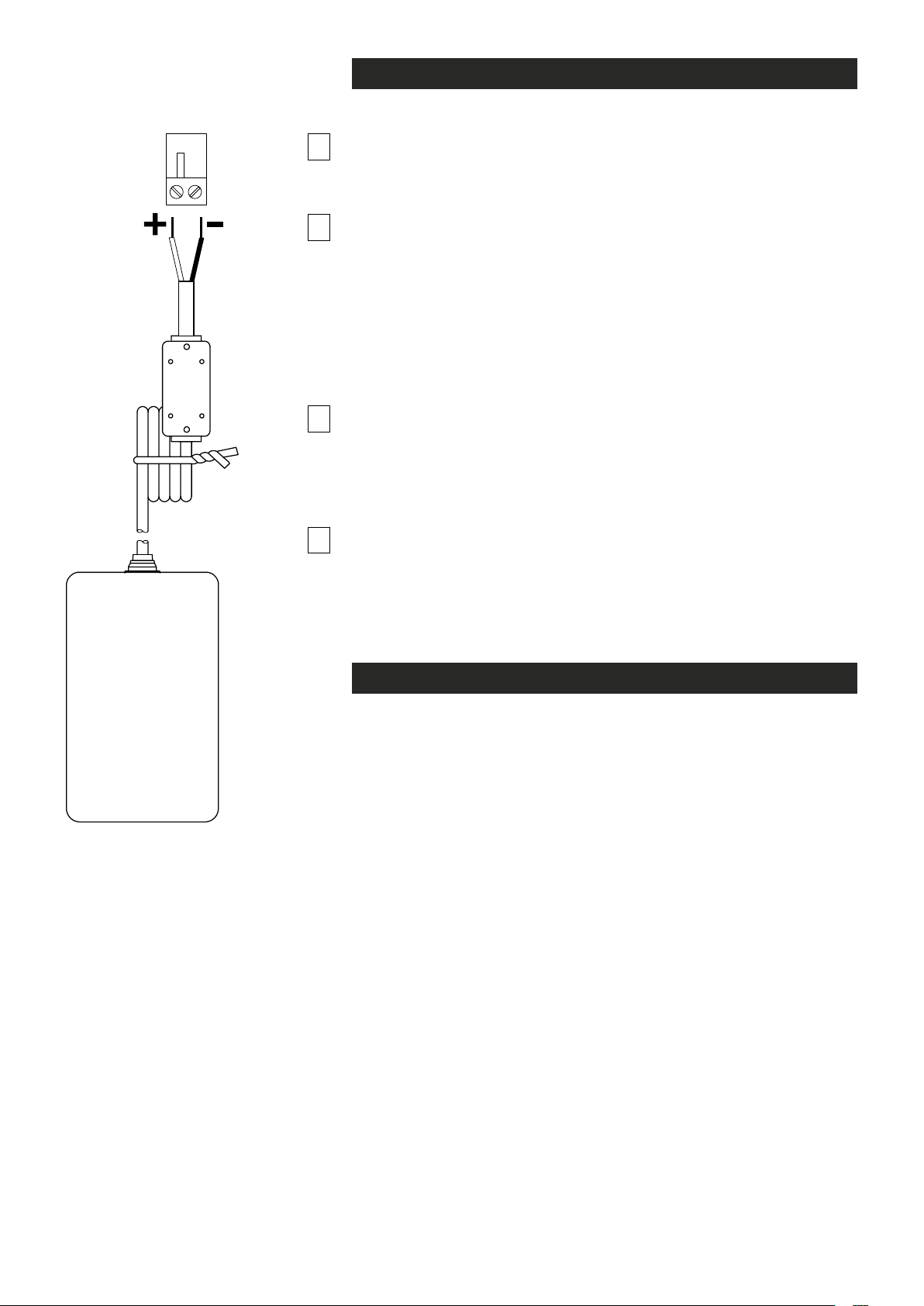
Install the temperature hardened stand-alone MPH200 series encoder to
1
the installation location. A +12 VDC supply voltage is provided by a CPS25x
series power supply (see example picture beside), or alternately through the
LAN cable (CAT5) when using Power over Ethernet (PoE+) technology.
2
3
Connect all needed signals to their respective connectors on the
device’s front panel:
• HD-SDI / CVBS video signals to the BNC female connector(s).
• Data and contact closure signals to the screw terminal connector.
• Audio signal(s) to the screw terminal connector.
• Ethernet network to Ethernet connectors.
Switch on the power and wait until the power led “M” lits green (start-up
time approx. 100 secs). This indicates that the device hardware is
operating properly and ready for usage.
Note! If led doesn’t lit green, refer to “M- LED indicator” section to
know the status of the device.
Log on to the device using the IP address assigned by DHCP server,
or locally from a Mgmt port (CLI) and then set all necessary settings in
the device.
4
Note! Device uses always two IP-addresses, one for encoder and an
another for internal switch management. By default device will
automatically assign IP addresses via DHCP.
contain DHCP server, then the MPH encoder shall use Zeroconf
(link-local) as DHCP fallback (see section below).
If network doesn’t
CPS25x series power
supply for MPH200 device.
Device’s IP address
There are two ways of assigning IP address to the MPH device. The IP
address can be automatically assigned via DHCP, or you can set it
manually as a static IP address. Factory default IP settings for the
device is DHCP enabled.
By default when you have DHCP server in the network, DHCP server
assigns an IP address automatically to the MPH encoder. The DHCP server
offers an IP address from its address pool when a device is starting up.
If DHCP server is not available device uses zero conguration (link-local
address) as DHCP fallback. With Zeroconf protocol MPH chooses an IP
address randomly in the IP range from 169.254.0.1 to 169.254.255.254.
Alternatively you can manually assign the IP address, subnet mask and
gateway address to the unit.
If there is no DHCP address in the network, the unit chooses randomly
an IP address from the private IP range 169.254.0.1 - 169.254.255.254.
In this case in order to nd the chosen IP address you have two options.
You can use Teleste MPH Discovery Tool to browse all the available
ONVIF compliment devices in the network, note that your PC IP address
should be in the same IP range. Second option is, connecting to the
MPH device locally via the serial port and use the CLI (Command Line
Interface) to see device IP address.
See section Network command to see how to change IP address via CLI.
4 MPH200 series video encoders WebUI user manual
Page 7
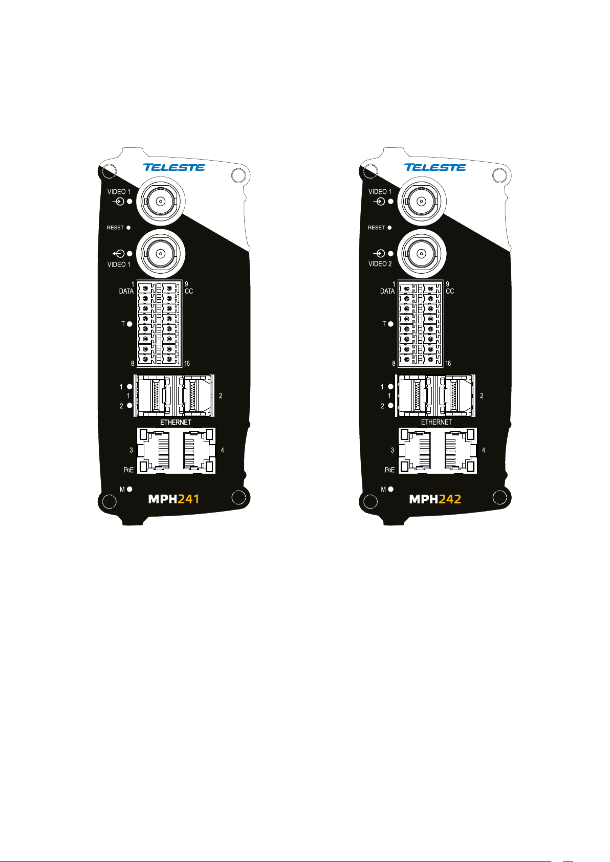
MPH200 series models
One video input (digital HD-SDI or analog CVBS). Two video inputs (analog CVBS).
MPH241 encoder supports both
digital HD (HD-SDI) and analog
CVBS video formats.
For HD-SDI operation the MPH241
needs to have the HD encoding
license MLH213 enabled.
5 MPH200 series video encoders WebUI user manual
Page 8
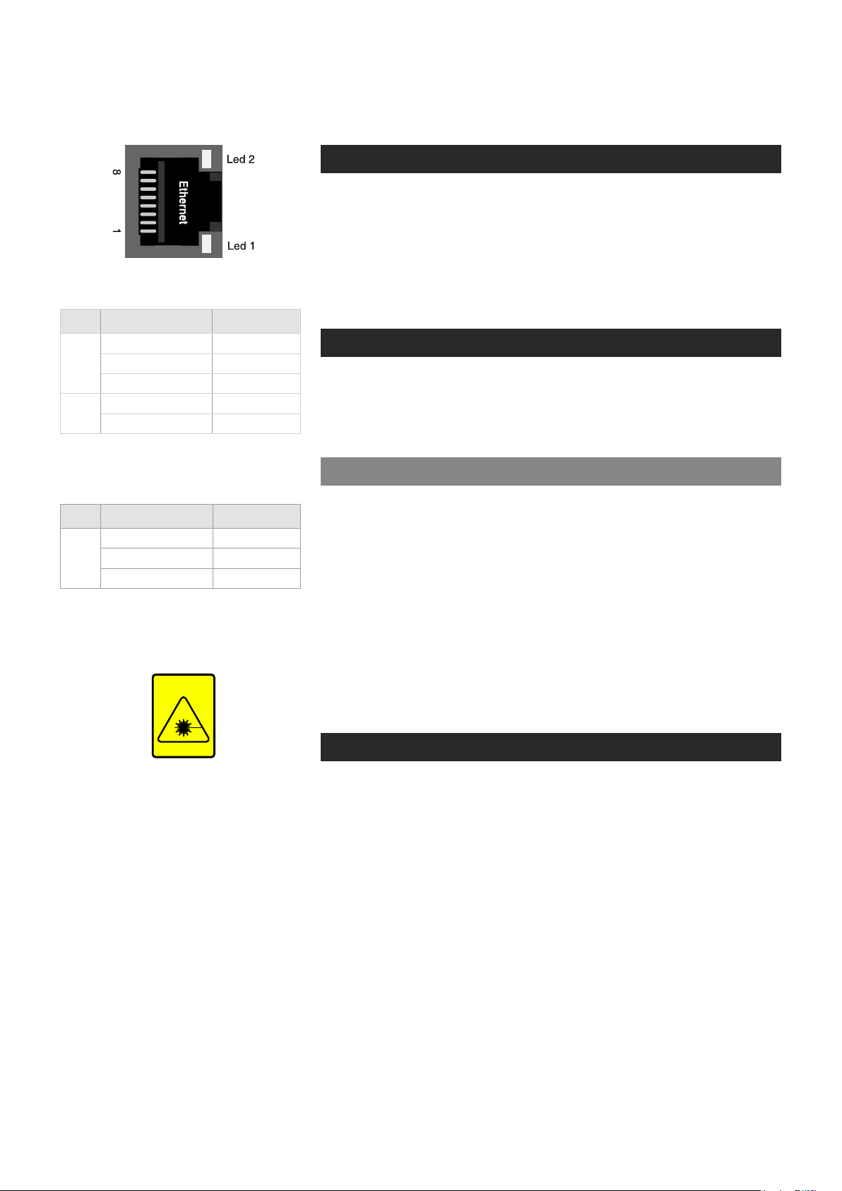
Ethernet interface
Electrical Ethernet connector (RJ-45).
Led Colour Mode
Green Link up
2
Blinking Green Trafc
OFF / Dark No link
Orange 1000 Mbps
1
OFF / Dark 100 Mbps
Ethernet port’s led indicator operation
(RJ-45 connector).
Ethernet connections
The unit has a built-in 4-port managed Ethernet switch and supports both
Fast Ethernet and Gigabit Ethernet connection speeds. Ethernet
interface type is either a xed electrical (copper), or has support for a
small form-factor pluggable transceiver (SFP) module. Supported SFP
transceivers are specied by Teleste. Please see the latest list of available
SFP products.
Local ports, electrical interfaces
Device include two (2) xed electrical Ethernet connectors. The electrical
Ethernet connector type is a RJ-45 female. The interfaces are supporting
10/100/1000Base-T operation (Gigabit Ethernet).
Power over Ethernet (PoE+) option
Led Colour Mode
Green Link up
SFP
Blinking Green Trafc
OFF / Dark No link
Ethernet port’s led indicator operation
(when SFP optical connector).
INVISIBLE LASER
RADIATION
CLASS 1
MPH200 series encoders supports PoE standard (PoE+ 802.3at class 4).
This means that the encoders can be powered through the LAN cable
without the need of individual power supplies. PoE is available from port
number three (3).
Requirements for the use of PoE:
• A Power over Ethernet (PoE) compliant switch or hub.
• MLH251 license activation.
Note!
MPH200 series device PoE port is only used to powered
device itself, it not provide output power to other devices.
Up-link ports, optical interfaces (SFP)
SFP modules for optical Ethernet operation are available with a variety of
different types (see the latest list of available SFP products), allowing users
to select the suitable module for to provide the required optical reach over
the available optical bre type. The optical connector type is LC/PC (single
or dual). Ethernet interface speed is 1000BASE-X (Gigabit Ethernet).
When installing the bre optic cable, do not exceed the minimum
bending radius when connecting cable to the system.
Optical Ethernet connection meets class 1 laser safety requirements of
IEC 60825-2: 2004 and US department of health services 21 CFR
1040.10 and 1040.11 (1990) when operated within the specied temperature, power supply and duty cycle ranges.
6 MPH200 series video encoders WebUI user manual
Page 9
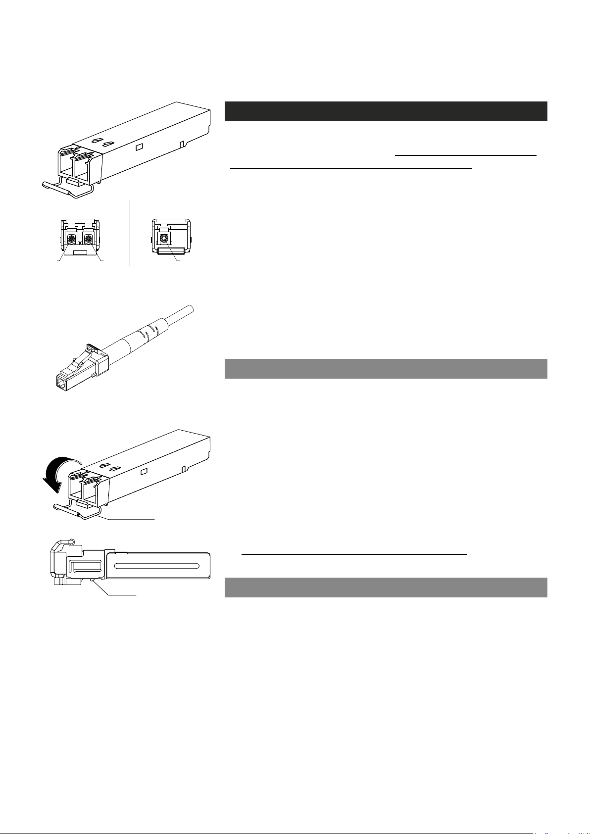
latch
2 fibre version 1 fibre version
Tx Rx Tx/Rx
SFP plug-in optical transceiver module.
How to unplug or plug-in the SFP transceiver module
If your up-link port requirements change, simply unplug the existing SFP
module, and plug-in the new module. The SFP transceiver modules
must be installed before the encoder is powered on. Installing SFP:
1. Switch off the unit supply voltage.
2. Mount the SFP transceiver to the unit (see bottom instructions).
3. Connect the bre optic cable(s).
4. Ensure that the remote end of the bre is already connected to an
active switch.
5. Switch on the unit supply voltage.
The SFP transceiver module has a bale-clasp latch that makes easier to
install or remove the module. Protect the SFP module by inserting a
clean dustplug into the module after you remove the ber cable. Be sure
to clean the optic surfaces of the ber cable before you plug the cable
into another module. When using 2 bre version SFP, select carefully
the correct optical port for TX and RX operation.
To unplug and plug-in the SFP module, follow these steps
Optical connector is the type of LC.
bale clasp
SFP module’s locking release points.
1. Open the bale clasp on the SFP module by pressing the clasp
downward until it is in a horizontal position.
2. Use a small at-blade screwdriver or
push on the hinge pin to unlock the SFP cage latch.
3. Grasp the SFP module by the bale clasp and gently pull it out of the
SFP cage
To plug-in the module:
1. Orient the transceiver with the bale clasp on the bottom, close the
bale clasp by pushing it up over the transceiver, then gently insert
the transceiver into the port until it clicks into place.
Note! Reboot the device when the SFP is changed.
.
other long, narrow instrument
to
Some generic notes for successful optical connections:
• Ensure that the ber patch cord is damage-free (ber condition can
be easily checked by a visible laser tester)
• Do not exceed the minimum bending radius of the bre
• Avoid sharp corners on cable shelves and in cable management
in overall
• Make sure that correct optical connectors are used
• Open connectors are always secured by dustcaps during maintenance
• Always before mating clean all connectors (wet cleaning by high
purity alcohol & drying, or dry cleaning with reel-based lint-free wipes,
ber adapters may require special ferrule end-face cleaning tools)
• Before making any visual inspections ensure that system has been
shutdown or no optical power is present
• For fault nding at least a optical power meter is required, a complex
ber cable environment may require use of an OTDR equipment.
7 MPH200 series video encoders WebUI user manual
Page 10
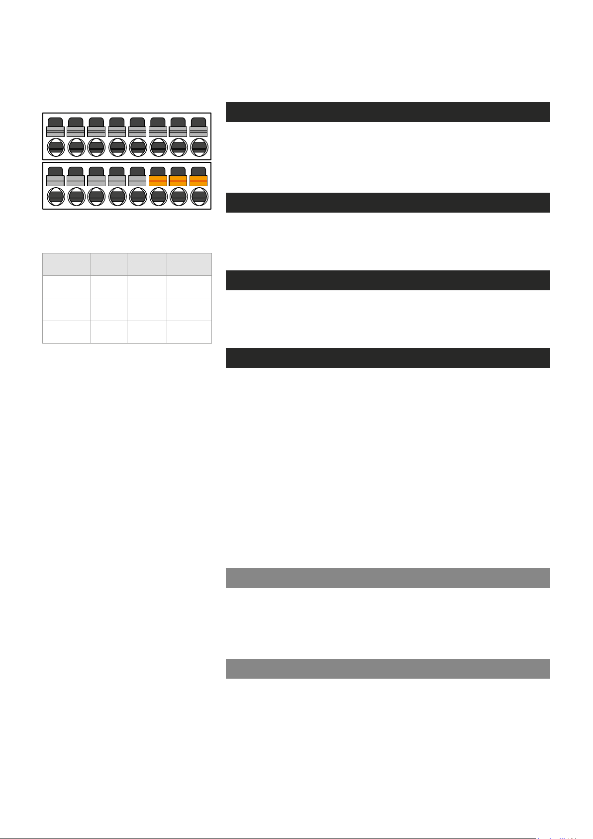
9 10
11
12 13 14 15 16
Management interface
General
MPH encoders support web user interface (WebUI), ONVIF congura-
tion interface and command line user interface (CLI) for various conguration purposes.
WebUI
1 2
PC/
PSION
Receive
data
Transmit
data
System
ground
4 5 6 7 8
3
D9
female
2 6
3 7
5 8 Ground
Screw
terminal
MPH
encoder
Mgmt
output
Mgmt
input
MPH series video encoders can be fully congured using Web user inter-
face (WebUI). You can access the Web user interface via web browser.
ONVIF
MPH series video encoder support ONVIF (Open Network Video
Interface Forum) global interface (version 1.02, Prole S).
Local management connection (CLI)
and management cable (CIC506)
pinout (D9 female/screw terminal).
CLI – command line interface
MPH series video encoder include a command line interface (CLI) for
conguration purposes. The CLI is a text-based interface that allows the
user to interact with the operating system by entering commands and
optional arguments. CLI is accessible through any terminal emulator
application (e.g. Hyper Terminal or PuTTY). The command structure is
the same for all session types. A typical CLI usage is to access the
device IP address settings. By default the data channel 2 is set for CLI
usage. The data channel 2 can be set to normal RS232 data mode with
WebUI when needed.
Note! Data 2 channel can be set either general RS232 data
transport mode or CLI mode (not simultaneously). The default
factory setting is CLI mode (Hard and soft factory reset restores
the data channel 2 to the CLI mode).
Local CLI connection
The local CLI session can be establish via data channel 2 by using a
serial data connection (RS232) cable (type Teleste CIC506).
Note! Data 2 port must be set to CLI mode .
Remote CLI connection
8 MPH200 series video encoders WebUI user manual
Over the IP network you can make Telnet or SSH connection to open the
command line interface remotely. SSH protocol secures your data session.
Note! Remote CLI is always available through network, even
when data 2 is congured for non-CLI usage.
Page 11
Web user interface (WebUI)
General
The MPH series video encoders can be fully congured using Web
user interface (WebUI). You can access the Web user interface via
your web browser, eg. Mozilla Firefox (recommended), Internet
Explorer, Apple Safari and Google Chrome. The Secure HTTP
(HTTPS, SSL 3.0 or TLS 1.0) feature is supported in MPH encoders.
System requirements for WebUI
• Network connection
• Ethernet cable
• Browser installed (Mozilla Firefox recommended)
Operation
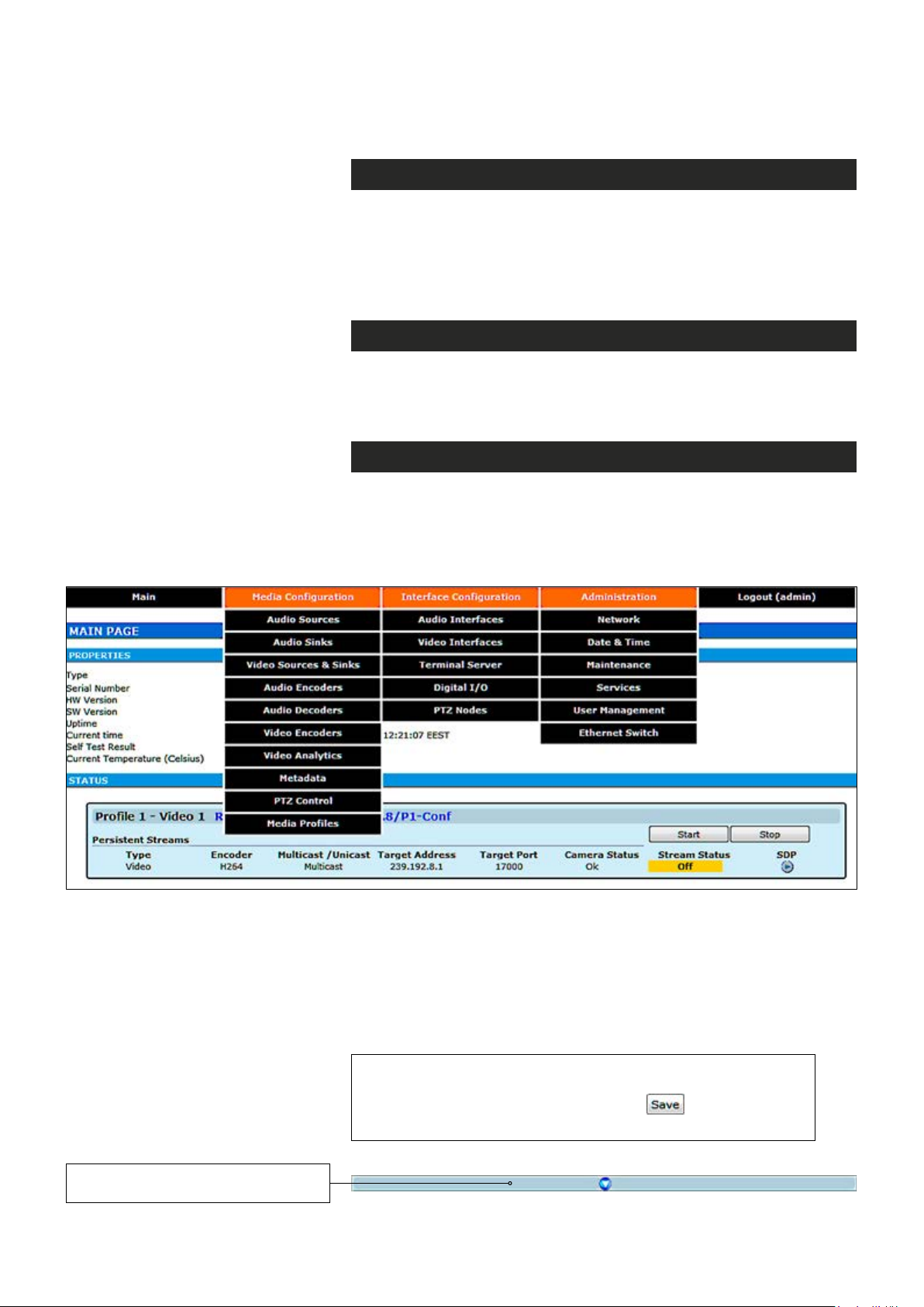
Web user interface consists of several menus and pages. Only one
page can be loaded at the same time. You can open a page by clicking
the related menu (see picture below).
The Web user interface has the following menu structure:
The information on conguration pages is shown in data elds or boxes.
The settings can be changed in the data elds and boxes having white
background. The unavailable or read-only options are grayed out. Place
the cursor in the desired data eld or box and enter a new setting.
Settings are entered by ticking a checkbox or clicking on a radio button,
by selecting from a pull-down list or by scrolling digits with the help of
spin buttons.
Press keyboard’s F5 button to refresh the WebUI page view.
When changing the settings, always click button to
conrm settings.
By clicking this button on a page
you can see more settings.
9 MPH200 series video encoders WebUI user manual
Page 12
Starting WebUI session
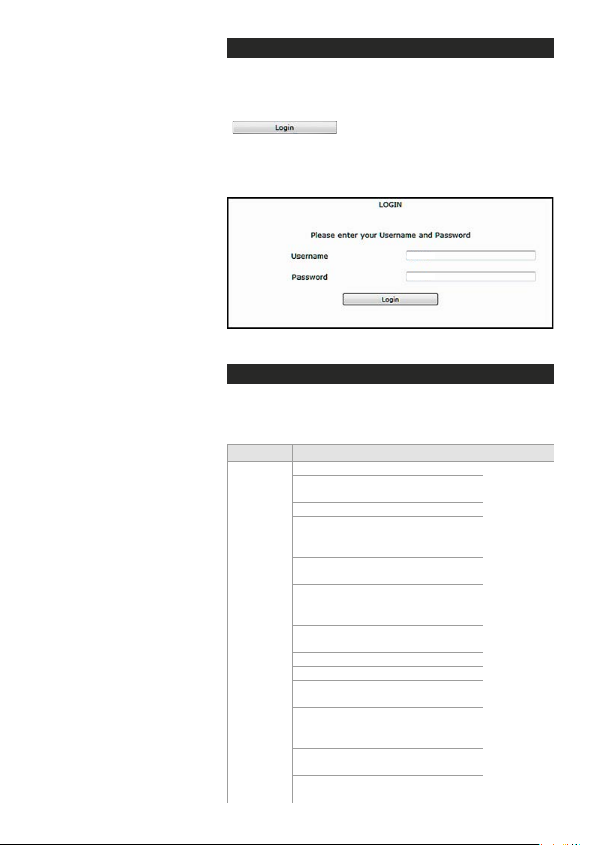
To create a WebUI session, rst enter the device IP address into the
web browser’s address bar (see section Device’s IP address). The
following LOGIN window appears on the screen. Enter the required
username and password (see bottom) in the elds and then click
to continue --> Web user interface’s MAIN
PAGE appears on the screen.
The Web user interface session to MPH series video encoder is
now activated.
admin
admin
Login window with the default username and password (for administrator).
User levels and permissions
The user management supports three different user levels of which each
has specic priviledges as shown below. The individual usernames, passwords and approved user level can be changed via the WebUI and CLI.
Page Operation User Operator Administrator
General Access
SDP download
Main
Video & Audio
Encoder
Maintenance
User
Management
Ethernet switch Conguration
Log download
Start/Stop
RTSP link copy
General Access
Save
Cancel
General Access
Backup
Restore
Reboot device
Soft factory reset
Hard factory reset
Software upload
Software download
License install
General Access
Save
Cancel
Change password
Change user group
View/Edit other users
Add User
x
x
x
x
x
-
-
-
-
-
-
-
-
-
-
-
-
x
x
x
x
-
-
-
-
x
x
x
x
x
x
x
x
x
x
x
x
x
-
-
-
-
x
x
x
x
-
-
-
-
Read and write
access to all
pages and
all settings
10 MPH200 series video encoders WebUI user manual
Page 13
Hint! You can open sdp le with the VLC player to
Shows installed and available
licenses for device.
view the stream, but notice the following requirements:
Stream port number should be even number. If you
are using multicast stream, ensure that you have set
valid multicast IP address. Make sure that windows
rewall is congured to allow this connection.
MAIN PAGE
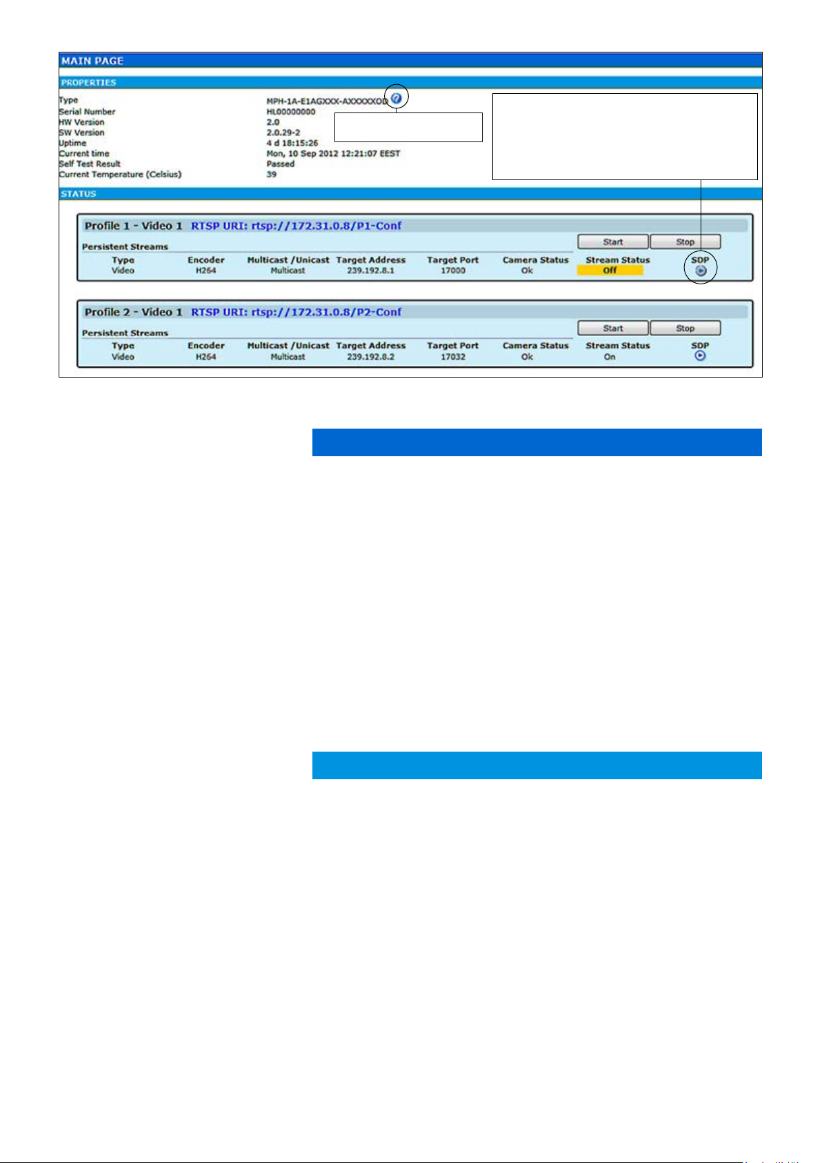
The MAIN PAGE is opened after the WebUI session has been established to the MPH200 series video encoder.
Type:
Serial Number:
HW Version:
SW Version:
Uptime:
Current time:
Self Test Result:
Current Temperature:
Type:
Encoder:
Multicast /Unicast:
Target Address:
Target Port:
Camera Status:
Stream Status:
SDP:
MPH200 encoder contains maximum six (6) encoding proles, which
can be individually congured. On this page you can see each prole’s
current status and start/stop their video streaming.
PROPERTIES
Device type (conguration map code)
Device serial number
Device hardware version
Device rmware version
Device uptime
Device current time
Device test result
Current ambient temperature
STATUS
Here you can see each
Stream type (Video)
Encoding format (H.264/MJPEG/MPEG-4,MPEG-2)
Video transmission mode (multicast/unicast)
Multicast: Multicast IP address / multicast group
Unicast: IP address of receiving decoder
UDP port number
Camera status (Ok/No signal)
Video stream status (On/Off)
Link to SDP le (Session Description Protocol). The SDP le contains
stream parameters that are meant for 3rd party applications (e.g. SW
decoders) to open/view the stream. SDP-link requires that video streaming is active.
prole’s current status.
Download short term logs:
Download long term logs:
11 MPH200 series video encoders WebUI user manual
Debug log le
Debug log le
Page 14
Event management system
MPH event management system
MPH encoders internally controls events as specied by ONVIF. Events
are generated from Digital IO inputs, motion detection, tampering
detection and video signal loss and each of those generate event with
different Topic. In addition to event topics, events contain data describing the event such as the video interface related, amount of motion and
threshold, etc.
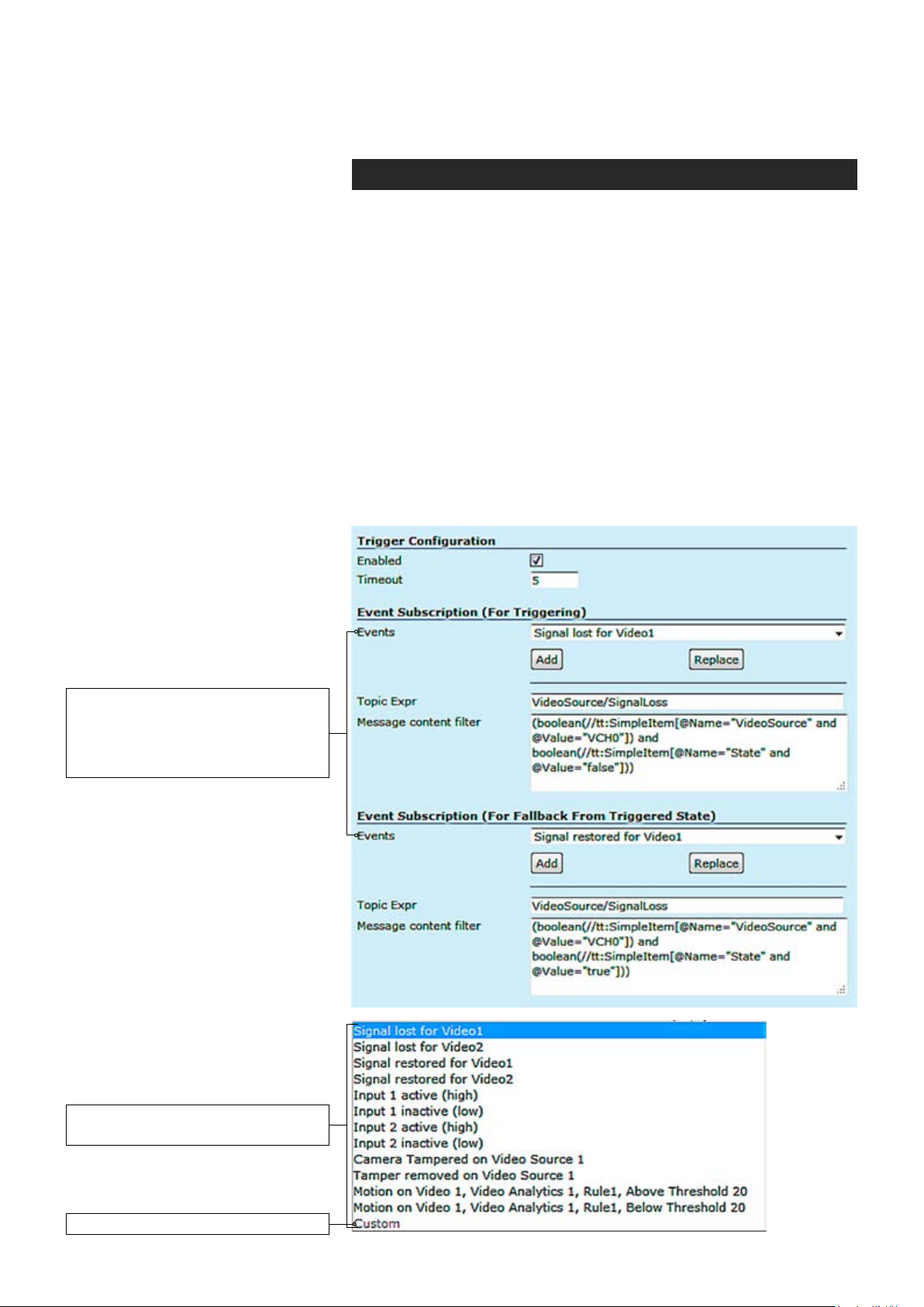
The event data is available in the “Message Content lter” box, which is
XPath format for matching XML content. Triggering occurs when dened
“Topic expression” and “message content lter” matches the internal event.
MPH encoder can trigger actions for video, audio (only MPH200 series)
and contact closers (Digital I/O) output. These events are also avail-
able for video management system to trigger congurable alarms. You
can add multiple event at the same time and each one triggers action.
Available events for triggering. First
choose the required event from the list
and then click Add button to select the
event -> The event data appears on
the Message content lter box.
The list of available events
for triggering.
Custom = Modied event for triggering.
12 MPH200 series video encoders WebUI user manual
Page 15
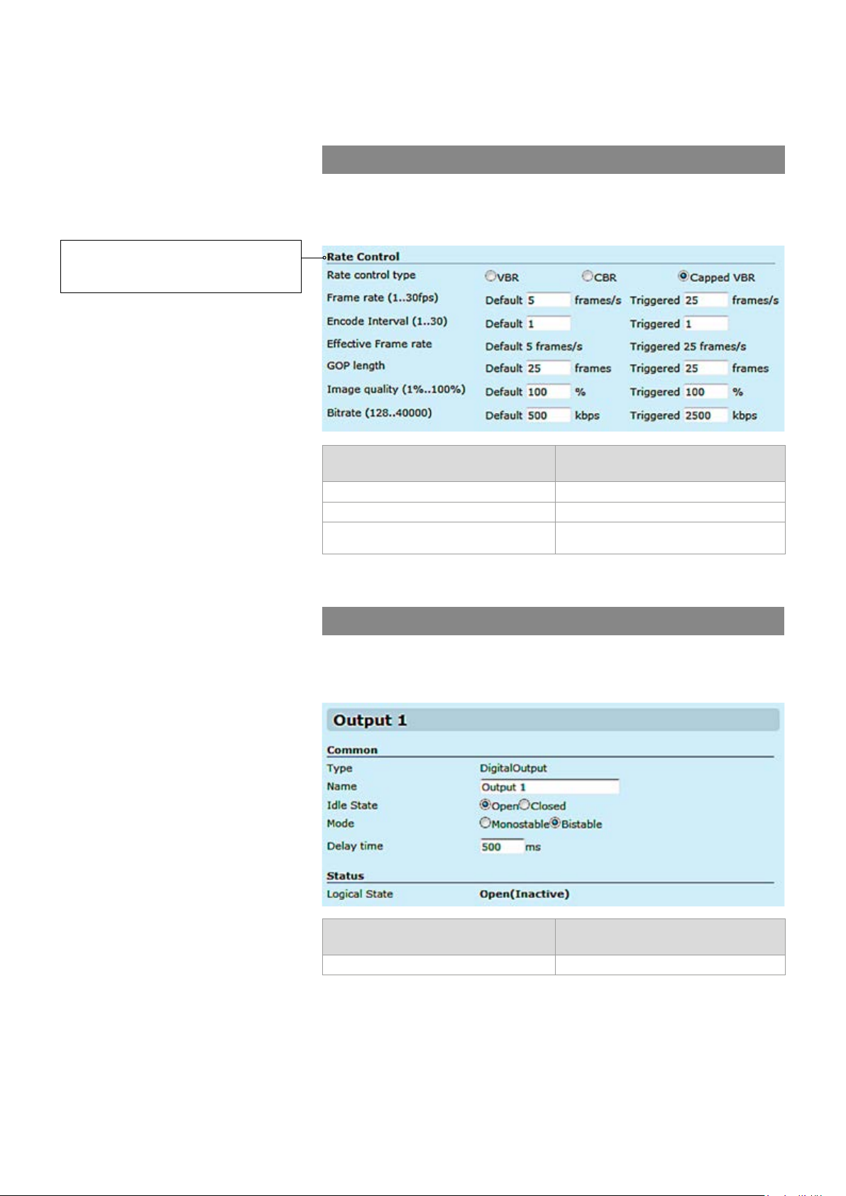
An example when the video bit rate
and frame rate change when an
event triggered.
Event management for video
For video it can trigger actions such as changing video settings, frame
rate, bit rate and video quality for each video prole based on events.
Event subscription (for triggering)
Signal lost for video 1 and 2 Signal restored for video 1 and 2
Camera tempered for video source 1 and 2 Temper removed for video source 1 and 2
Motion detection above the threshold for
video 1 and 2
Event subscription (for fallback from
triggered state)
Motion Detection below the threshold for
video 1 and 2
Available events for video.
Event management for contact closure (digital I/O)
For contact closure it can trigger actions such as changing output state
in case of an event.
Event subscription (for triggering)
I/O Inputs activation I/O Inputs deactivation
Event subscription (for fallback from
triggered state)
Available events for contact closure.
13 MPH200 series video encoders WebUI user manual
Page 16
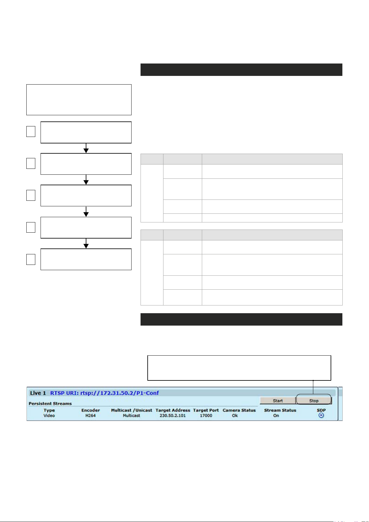
Conguring video channels
Video connection
Note! MPH encoder has automatic
NTSC/PAL video format detection.
When changing the video format, the
device must reboot.
1
2
VIDEO ENCODER CONFIGURATIONS
3
4
5
VIDEO INTERFACES
(Physical video input)
VIDEO SOURCE CONFIGURATIONS
(Video overlay settings)
(6 encoding combinations)
MEDIA PROFILE CONFIGURATIONS
(up to 12 media profiles)
MAIN PAGE
(Start / Stop video streaming)
Step-by-step owchart how to congure
video channel in the MPH encoder.
MPH encoder is available in one and two video input models. One
channel model has support for
channel model has support only for
CVBS or HD-SDI video signal,
CVBS video signal.
One channel
two
(CVBS input) model has equipped with additional loop-though output
connector. The video connector type is a BNC female. The video input
impedance is 75 Ω. The nominal input level is 1 Vpp. Video inputs are
equipped with dual colour VIDEO indicator led’s on the front panel.
Video port settings can be congured from web user interface (WebUI).
Led Colour Video mode
Green
(Short)
Video 1
Led Colour Video mode
Video 2
Blinking
Green
Orange
Off / Dark Power is OFF or device is restarting.
Green
(Short)
Blinking
Green
Orange
Off / Dark
Video connector is used as video input and is locked
to valid video signal
The video input is not used in any active media
prole, but is locked to video
Video connector is used as video input, but no valid
video signal is detected
Video connector is used as video input and is locked
to valid video signal
The video input is not used in any active media
prole, but is locked to video
Video connector is used as video input, but no valid
video signal is detected
Power is OFF or device is restarting, or congured
for loop-through output (1-ch version only)
Video channel conguration
MPH is an ONVIF compliant encoder and video channel conguration is
designed according to ONVIF standard.
Note! Before modifying the conguration of a video prole, make
sure that video stream is stopped on the MAIN page (changing
only encoding parameters don’t require stopping of the stream).
14 MPH200 series video encoders WebUI user manual
Page 17
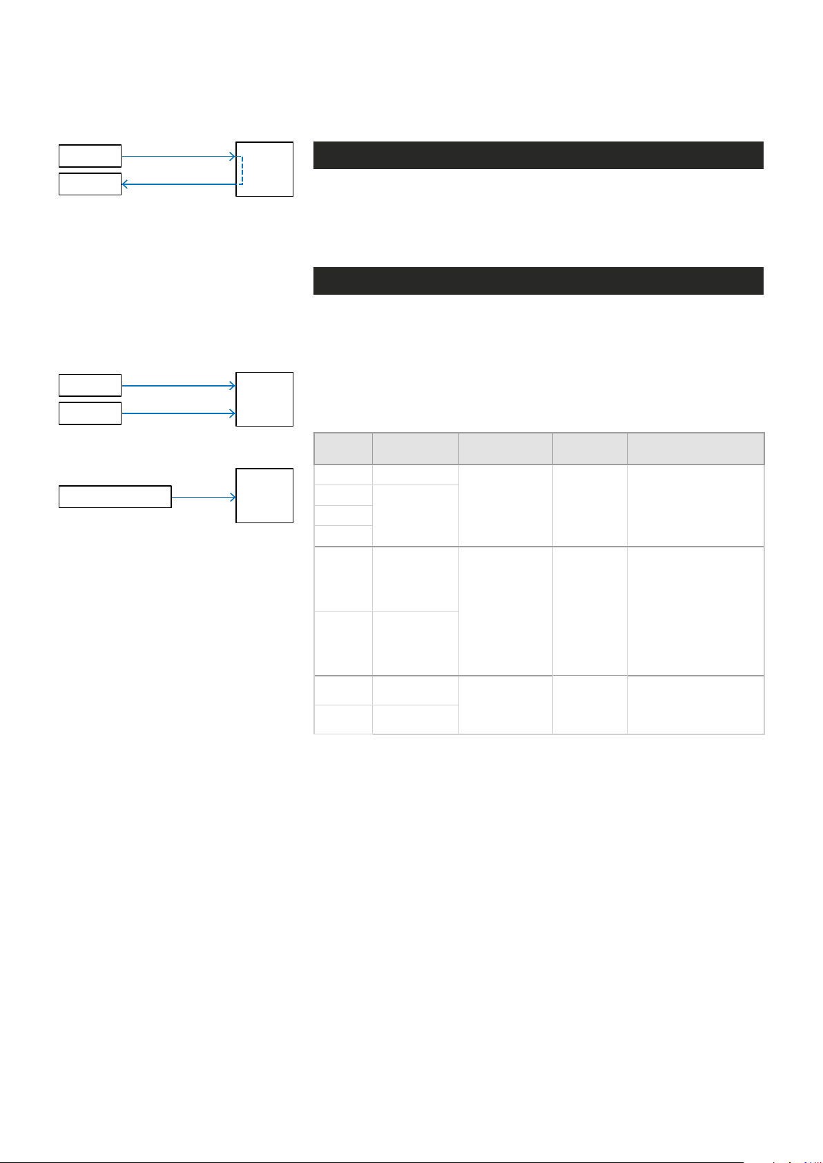
Camera
Monitor
CVBS
loop-through
MPH241 contains one video input
(with loop-through).
Note! One channel MPH encoder’s
second video connector is loopthrough port for an analog monitor.
It is designed to transmit the same
analog video signal out that is
received from video input.
Camera 1
Camera 2
CVBS
CVBS
MPH
MPH
Video streaming methods
Video input is the physical video connector (BCN female) available for
video signal. Naturally each video input can be connected to a camera or
any other standard video source. The default video input mode is set to
PAL/NTSC format (CVBS). MPH241 model has also support fot HD-SDI.
High-denition serial digital interface (HD-SDI)
MPH241 encoder supports HD-SDI digital video interface. HD-SDI inter-
face is dened by SMPTE 292M standard and allows bitrates up to 1.485
Gbit/s. Progressive input signals are recommended to provide the best
picture quality. The HD-SDI support can be enabled with MLH213 license.
When changing the video format from CVBS to HD-SDI, the device must
reboot. The loop-through port is not available in HD-SDI mode.
MPH242 contains two video inputs.
HD video camera
HD-SDI
MPH
MPH241 encoder supports HD-SDI digital video format up to 1080p resolution
(when license MLH213 enabled) .
Input
Signal
720p25 1...25fps
720p30
720p60
1080i50 1...25fps
1080i60 1...30fps
1080p25 1...25fps
1080p30 1...30fps
Output frame/
eld rates
1...30fps720p50
Resolutions Coding Notes
1280x720,
QCIF, CIF, 4CIF
1920x1080),
QCIF, CIF, 4CIF
1920x1080),
QCIF, CIF, 4CIF
Progressive
Field coded
Progressive
Supported HD signal formats and encoding formats.
Input signal is progressive, thus deinterlace is
not needed neither at
encoder or decoder side
Input signal 1080i is
interlaced format
containing 60 elds/s.
Transmitted video
stream is interlaced
(eld-coded), thus
deinterlacing at decoder
side is required when
display is progressive
Input signal is progressive, thus deinterlace is
not needed neither at
encoder or decoder side
15 MPH200 series video encoders WebUI user manual
Page 18
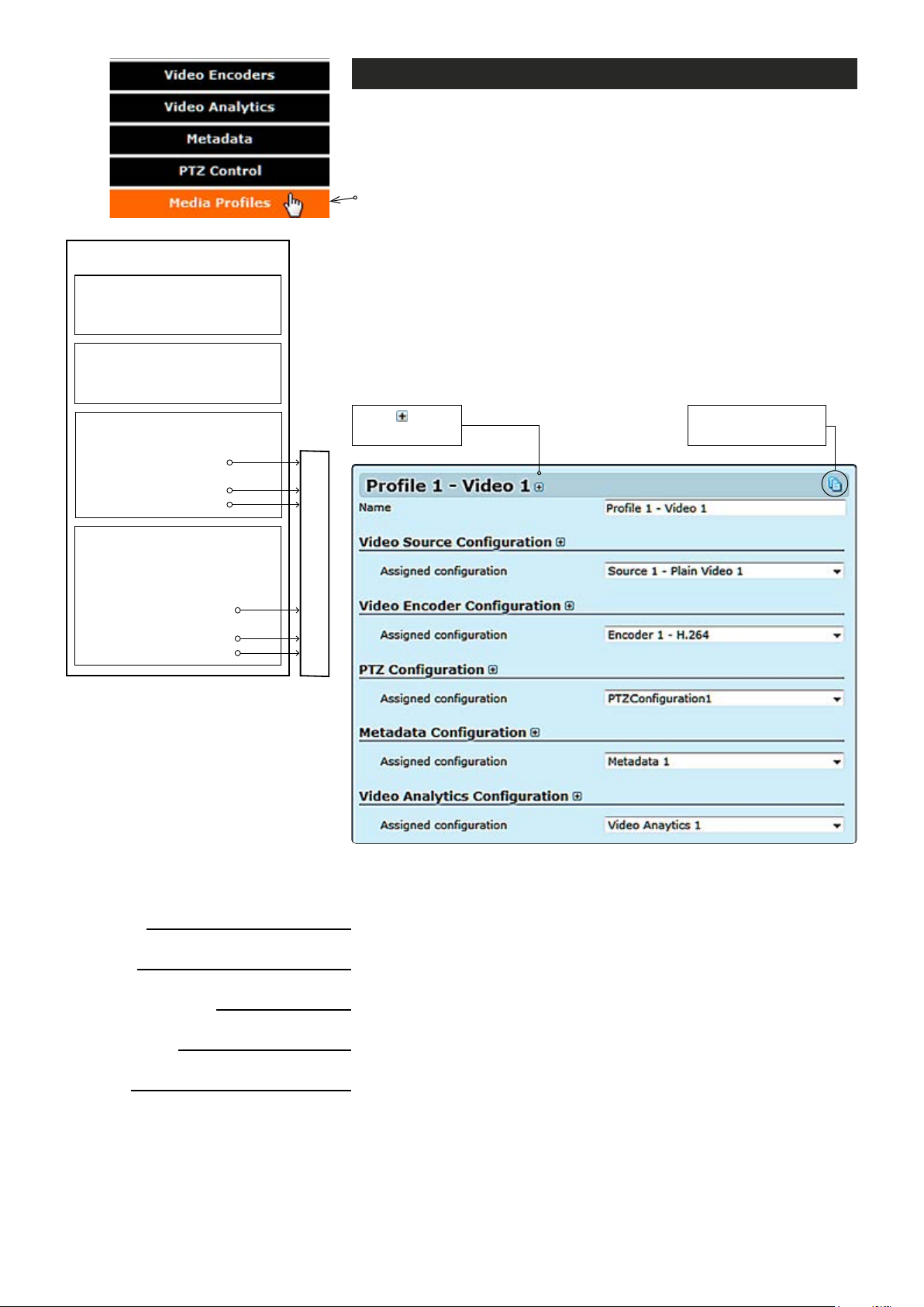
MEDIA PROFILE
Media prole (video)
MPH series encoders has a total of six (6) media proles. Each media
prole can be set separately for individual resolution, frame rate, GOP
structure and bitrate, within the processing power of the device.
Click “Media Proles” under the Media Conguration menu. Media
Prole Congurations page appears on the screen. On this page you
can associate virtual video sources with physical video inputs and
encoding proles.
VIDEO INTERFACE
•
Brightness, contrast & saturation
•
Privacy zone masking
VIDEO SOURCE CONFIGURATION
•
Physical video interface selection
•
Text overlay
ENCODER CONFIGURATION
•
Destination IP address
- primary stream
•
Additional IP address(es)
- stream multiplication
•
Dynamic streams (RTSP)
• Events
• Analytics (Motion detection,
tampering detection
• Destination IP address
- primary stream
• Additional IP address(es)
- stream multiplication
• Dynamic streams (RTSP)
METADATA
Description how the video encoder,
a video source and video input is
assembled to the media prole.
Click to see
more settings.
Streams output (RTP)
By default this page contains six different media proles.
Notes! It is not possible to change encoding format /resolution
and video input settings on this page. Before modifying the proles
the video stream must be stopped on the MAIN page.
Click this to create
copy from prole.
MEDIA PROFILE CONFIGURATIONS page.
Name:
Video Source Conguration
Assigned conguration:
Video Encoder Conguration
Assigned conguration:
PTZ Conguration
Assigned conguration:
Metadata Conguration
Assigned conguration:
Video Analytics Conguration
Assigned conguration:
16 MPH200 series video encoders WebUI user manual
User dened alias name for
_________________________________________________________
Select assigned video source conguration.
_________________________________________________________
Select assigned video encoder conguration.
_________________________________________________________
Select assigned PTZ conguration.
_________________________________________________________
Select assigned metadata conguration.
_________________________________________________________
Select assigned video analytics conguration.
media prole (max 63 chars).
Page 19
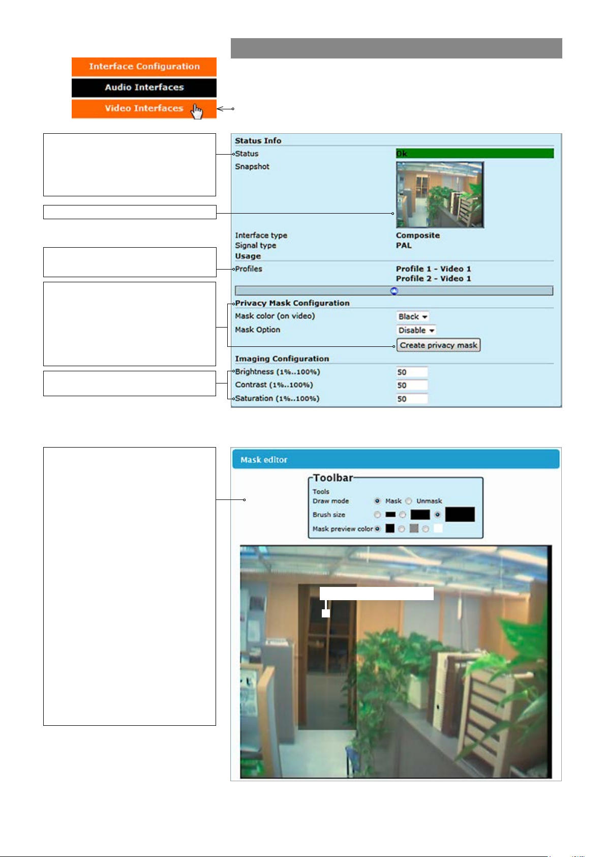
Video status. The colour bar reect
the status of the video. Green colour
bar means that there is video signal.
Yellow colour bar with text tells that
there is no video.
Screenshot from the current video.
Indicates what media prole is using
this video interface.
When monitoring an area for security,
there may be certain parts within the
camera’s eld of view that need to be
kept private. Masking is a feature that
enables these areas to be concealed
from view.
Video interfaces
Click “Video Interfaces” under the Interface Conguration menu. Video
Interfaces page appears on the screen. In this page you can see the
number of physical video inputs available and adjust the brightness,
contrast and saturation values for them.
Brightness, Contrast and Saturation
values for the video channel.
User can congure the encoder to
automatically hide certain areas with
a mask, which can be adjusted in
terms of its colour
Mask editor shows a screenshot from
camera view and overlays a
translucent mask on the image.
.
Draw mode: Masked (highlighted)
areas are private areas that are
removed (concealed) from
camera’s view.
Brush size: Select brush size
for masking.
Mask color: Depending on the
brightness of the image snapshot,
appropriate mask preview color can
be chosen. This color affects the
preview on mask editor only and
doesn’t reect on the streaming video.
VIDEO INTERFACES page.
Masked/Highlighted area
MASK EDITOR page contains settings for hiding certain areas from the
encoded picture.
17 MPH200 series video encoders WebUI user manual
Page 20
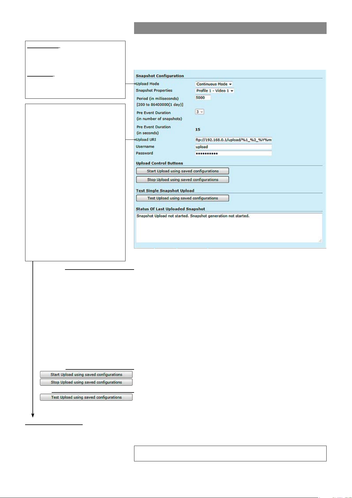
JPEG snapshot conguration
Continuous: Device generates a
snapsthot at specied interval (period)
and sends the images to congured
Additionally there is a JPEG image capture feature that allows taking
JPEG snapshots from the video and storing them into a ftp server. It is
also possible view JPEG captures with http.
FTP server.
Triggered: Snapshots are generated
when internal event triggers it. Triggering event can be motion detection,
tampering or digital IO event.
%d: The day of the month as a decimal
number (range 01...31).
%H: The hour as a decimal number using a
24-hour clock (range 00...23).
%I: The hour as a decimal number using a
12-hour clock (range 01...12).
%m: The month as a decimal number
(range 01...12).
%M: The minute as a decimal number
(range 00...59).
%S: The second as a decimal number
(range 00...60).
%4: The milliseconds as a decimal number
(range 0000...9999).
%p: Either “AM” or “PM” according to the
given time value, or the corresponding
strings for the current locale. Noon is
treated as “PM” and midnight as “AM”.
%y: The year as a decimal number without
a century (range 00...99).
%Y: The year as a decimal number
including the century.
%1: Device hostname (manually conf. or
received from DHCP-server).
Snapshot Conguration:
Upload Mode:
_________________________________________________________
Snapshot generation can operate in two separate modes: Continous
and triggered mode.
Snapshot Properties:
Period (in milliseconds):
Pre Event Duration:
Keeps the event state unchanged for the dened period for instance if an
Specied interval when device generates a snapsthot.
After event has occured, device sends rst congured number of images
before the event and then continues sending images until dened timeout
[ms] elapses.
Upload URI:
Denes the remote FTP server address. URI can contain arbitrary
directory path and device shall create the directory if it does not yet exist.
Username:
Password:
Set username for server.
Set password for server.
Note! Hard Factory reset restores admin password to defaults.
Upload Control Buttons:
_________________________________________________________
Starts uploading using saved congurations.
:
Stops uploading using saved congurations.
Test single Snapshot Upload:
Status of last Uploaded Snapshot:
_________________________________________________________
Tests upload using saved congurations.
:
_________________________________________________________
Shows status of last uploaded snapshots.
Snapshot URI example:
ftp://192.168.0.247/upload/%1_%Y%m%d/camera1_%H%M%S_%4.jpg expands to:
ftp://192.168.0.247/upload/MPH102-RD00101126_20140424/camera1_183059”)_830.jpg
Trigger Conguration
See section “Event management system” from page 31 for more details.
18 MPH200 series video encoders WebUI user manual
Page 21

Video source and sinks
Click “Video Source and Sinks” under the Media Conguration menu.
Video Source Congurations page appears on the screen. Video
overlay settings can be changed on this page, you can enter a text and
time/date on the video.
Note! Date and time settings can be changed from Date & Time page.
There are four different virtual video sources available for video inputs.
This feature allows you to set four different views with/without video
overlay content.
VIDEO SOURCE CONFIGURATIONS page.
19 MPH200 series video encoders WebUI user manual
Page 22
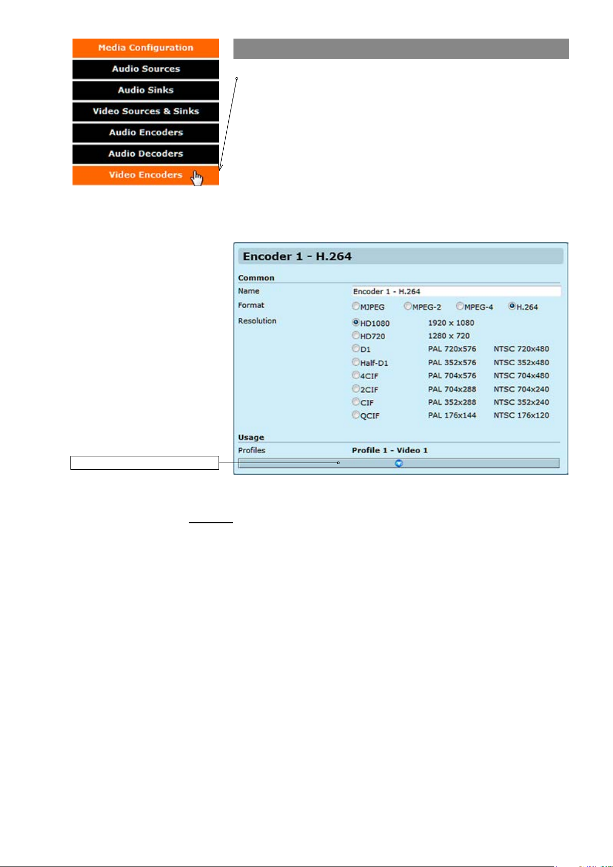
Video encoders
Click “Video Encoders” under the Media Conguration menu. Video
Encoder Congurations page appears on the screen. Video encoding
settings can be congured on this page, e.g. select format (MJPEG,
MPEG-2, MPEG-4 and H.264), set resolution, bit rate, frame rate and
multicast IP/port settings for each prole.
This page contains (by default) six different customizable encoding
proles. This feature allows you to set six different video encoding
combinations, each with their own settings.
On this page you can also add multiplied multicast/unicast streams from
each encoder.
Click this to see more settings.
Common
Name:
Resolution:
VIDEO ENCODER CONFIGURATIONS page.
_________________________________________________________
User dened alias name for
Video resolution, either digital HD1080 or HD720, or analog D1, Half-
D1, 4CIF, 2CIF, CIF or QCIF.
video prole (max 63 chars).
20 MPH200 series video encoders WebUI user manual
Page 23
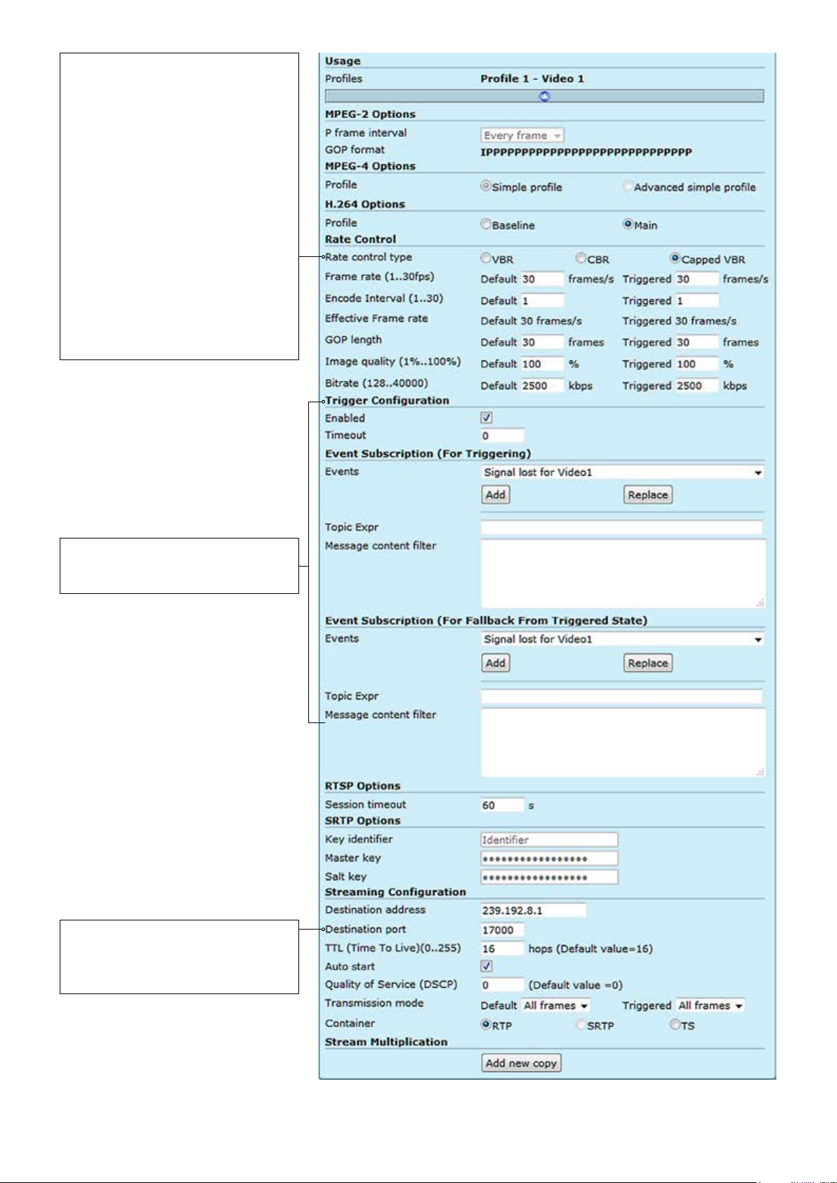
VBR (Variable Bit Rate) video aims at
constant quality, but as the bit rate
uctuates over time.
CBR (Constant Bit Rate) video
uctuates in quality, while its multiplexing behaviour is easy to predict.
Because in unconstrained VBR video
the bit rate uctuation might be too
large, capped VBR video is proposed
as an alternative. Capped VBR video
aims at a constant quality, but when in
certain intervals this requires a too
high bit rate, the bit rate is limited
(i.e.,capped) in order to support more
video ows on the links, at the
expense of a quality reduction.
Trigger Conguration
See section “Event management
system” from page 60 for more details.
Note! Only even port numbers can
be used for RTP, and then the
following odd port number shall be
used for RTCP (RFC 1889).
VIDEO ENCODER CONFIGURATIONS page.
21 MPH200 series video encoders WebUI user manual
Page 24

Usage
Proles:
MPEG-2 Options:
P frame interval:
GOP format:
MPEG-4 Options:
Simple prole:
Advanced simple prole:
H.264 options:
Baseline:
Main:
Rate control:
Rate control type:
Frame rate (1...30fps):
Encode Interval (1...30):
GOP length:
Image quality (1%...100%):
Bitrate (128...20000):
Trigger conguration:
Enabled:
Timeout:
Event subscription (for triggering):
Events:
Topic Expr:
Message content lter:
RTSP options:
Session timeout:
Streaming Conguration:
Destination address:
Destination port:
TTL (Time To Live):
Auto start:
_________________________________________________________
Here you see how the media prole is assigned to a video source.
_________________________________________________________
There are three options; Every frame = IP, Every second frame = IBP,
Every third frame = IBBP.
MPEG-2 GOP format.
_________________________________________________________
Simple Prole (SP) is recommended only for decoder compatibility.
Interlacing toolsets are not used.
Advanced Simple Prole (ASP) Level 5 enables Macroblock-Adaptive
Frame/Field Coding (MBAFF) which offers better image quality and
better compression ratio with interlaced video signal. Recommended
choice when interlaced stream is selected (D1 and Half-D1 resolutions).
_________________________________________________________
Baseline Prole (BP) Level 3 is recommended only for decoder compat-
ibility. Interlacing toolsets are not used.
Main Prole (MP) Level supports eld encoding which which offers
better image quality and better compression ratio with interlaced video
signal. Recommended choice when interlaced stream is selected (D1
and Half-D1 resolutions).
_________________________________________________________
Denes video bitrate mode. There are three options available, variable
bitrate (VBR), constant bitrate (CBR) or capped VBR. Rate control is a
trade off between quality uctuations and bit rate variability.
Denes video frame rate (adjustable 1...30fps for PAL/NTSC).
Denes encoding frame interval; for instance when encoding interval is 1,
all frames are encoded, value 2 means, every second frame is encoded.
Species the order in which intra- and inter-frames are arranged. The
GOP is a group of successive pictures within an encoded video stream.
Each coded video stream consists of successive GOPs. From the pic
tures contained in it, the visible frames are generated. For instance if you
25 FPS video stream, GOP= 25 means one I-frame per full frame.
GOP = 13 means two I-frames per full frame. GOP = 5 means 5 I-frames,
20 p-frames per second
Encoded video image quality, can adjust in VBR or capped VBR mode.
Encoded video bitrate, 128Kbps...15Mbps.
_________________________________________________________
Enables or disables the trigger feature.
Keeps the event state unchanged for the dened period for instance if an
event clears quickly, it does not change its state for the dened timeout,
recommended 5 seconds.
_________________________________________________________
Select the event type.
The topic expression of the event.
Event description, lter and values.
_________________________________________________________
Timeout for RTSP session
_________________________________________________________
Destination IP address. Multicast: Multicast IP address / multicast group.
This multicast IP address has to be same at both encoder and corresponding decoders. Unicast: IP address of receiving decoder.
UDP port number (0...65536). This number has to be same at both
encoder and decoder pairs. Use even port numbers only.
Time-To-Live for video packets = number of hops that a packet is permitted to travel before being discarded by a router
(0...255)
.
Video streaming will automatically start after reboot. Changing autostart
does not immediately start or stop streams.
22 MPH200 series video encoders WebUI user manual
Page 25
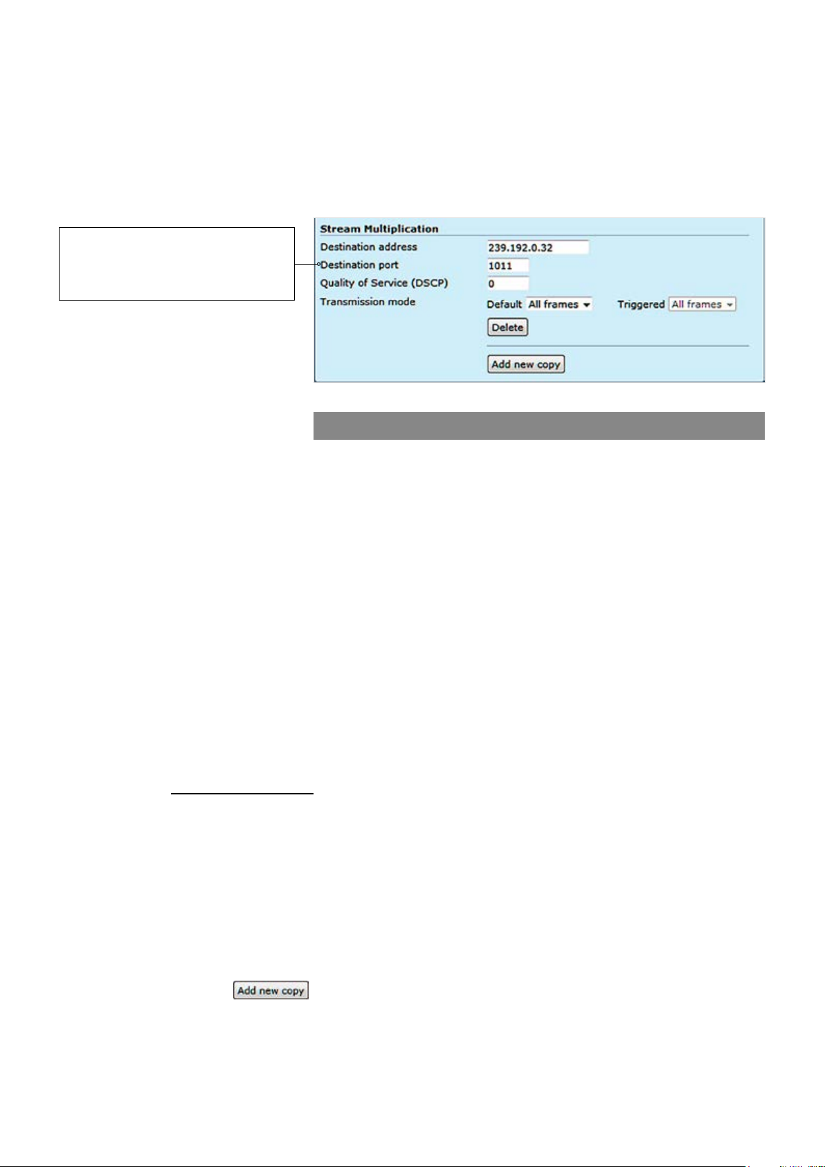
Quality of Service (DSCP )(0...63):
Transmission mode:
Container:
Note! Only even port numbers can
be used for RTP, and then the
following odd port number shall be
used for RTCP (RFC 1889).
Stream multiplication:
Destination address:
Destination port:
Quality of Service (DSCP/DiffServ ):
Transmission mode:
(Differentiated Services Code Point) eld lets you set bits in the stream IP
header allowing a network device to apply rules such as how the packet is
forwarded in the network and QoS (Quality of service) management.
All frames is the default option and enables the encoder to pass (stream)
all frames (I and P frames). I frames enables encoder to send only
I-frames, meaning ltering all P frames. Paused = pause streaming.
RTP (Real-time Transport Protocol), SRTP (Secure Real-time Transport
Protocol) or TS (MPEG transport stream).
Video stream multiplication
Each video encoding prole can be assigned with ve (5) different destination addresses (primary stream and additional streams). These addresses
can be freely set to unicast, multicast or a combination of these. In addi-
tion there is a tick box that enables to lter out P-frames from each output
stream for low frame rate applications. This approach provides for a very
cost efcient dual streaming in situations where the low frame rate stream
is a direct subset of the higher frame rate stream. In practise this means
that the number of I-frames is the common nominator. As an example, one
MPH241 unit can stream (unicast or multicast) 2 x D1@25fps for monitoring and 4 x 2CIF@3fps (unicast or multicast) for recording simultaneously.
The precondition is, the number of I-frames per second in the primary
stream should match to frame rate of the low frame rate stream. In the
example above the I-frame interval of the primary stream would need to be
8 (GOP = IPPPPPPPIPPPPPPPIPP…) generating 3 I-frames per second
thus resulting in 3fps stream when P-frames are ltered out. The use of
multiple destination addresses up to a certain degree doesn’t load the
MPU; however one should take into account that the aggregate bit rate of
all output streams does not exceed the capacity of the 100Mbps interface.
_________________________________________________________
Destination IP address. Multicast: Multicast IP address / multicast group.
This multicast IP address has to be same at both encoder and
corresponding decoders. Unicast: IP address of receiving decoder.
UDP port number (0...65536). This number has to be same at both
encoder and decoder pairs. Use even port numbers only.
Differentiated Services Code Point eld lets you set bits in the stream IP
header allowing a network device to apply rules such as how the packet is
forwarded in the network and QoS (Quality of service) management.
All frames is the default option and enables the encoder to pass (stream)
all frames (I and P frames). I frames enables encoder to send only
I-frames, meaning ltering all P frames. Paused = pause streaming.
:
Adds new copy from stream.
23 MPH200 series video encoders WebUI user manual
Page 26
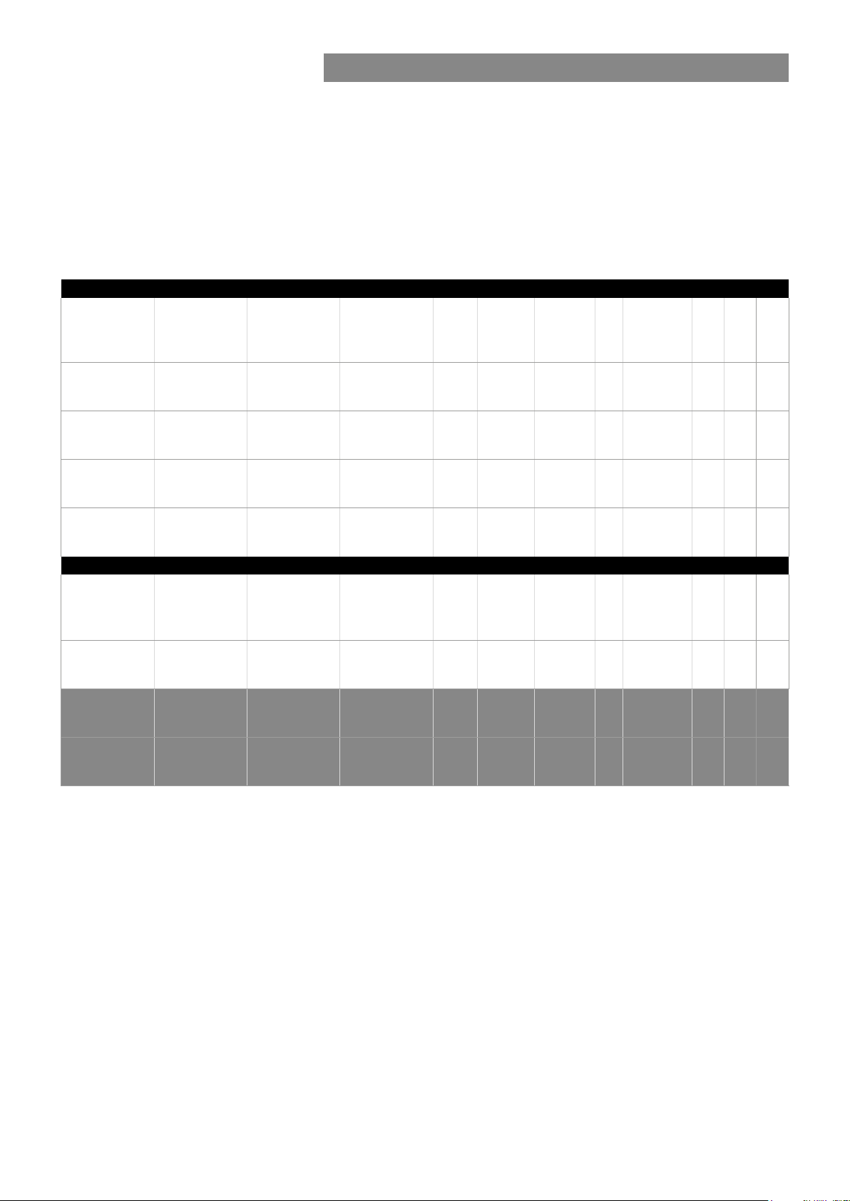
Video streaming performance
The following performance table shows the performance of MPH200
devices in encoding and streaming video signal per video input
simultaneously.
Total video sessions = original video stream + multiplied streams.
SRTP (Secure Real-time Transport Protocol) = encrypted RTP stream.
De-interlacing is done by choosing right prole.
Congurations for single input in two channel encoder (NTSC/PAL)
MPEG-2/
MPEG-4/H.264
Encoder 1
D1 30fps
6Mbps
D1 30fps
6Mbps
D1 30fps
6Mbps
CIF 30fps
1.5Mbps
MPEG-2/
MPEG-4/H.264
Encoder 1
D1 30fps
6Mpbs
1080p 30fps
20Mbps
MPEG-2/
MPEG-4/H.264
Encoder 2
4CIF 30fps
6Mbps
4CIF 15fps
6Mbps
2CIF 30fps
3Mbps
CIF 30fps
1.5Mbps
Congurations for single input in single channel encoder (NTSC/PAL)
MPEG-2/
MPEG-4/H.264
Encoder 2
D1 30fps
6Mpbs
MPEG-2/
MPEG-4/H.264
Encoder 3
CIF 30fps
1.5Mbps
MPEG-2/
MPEG-4/H.264
Encoder 3
4CIF 30fps
6Mbps
MPEG-2/
MPEG-4/H.264
Encoder 4
CIF 30fps
1.5Mbps
MPEG-2/
MPEG-4/H.264
Encoder 4
4CIF 30fps
6Mbps
Privacy
zone
De-
masking
interlace
30 fps Yes
15 fps Yes
Yes
Yes
Privacy
zone
De-
masking
interlace
30fps Yes
Yes
Motion
detection
QCIF
5fps
QCIF
5fps
QCIF
5fps
Motion
detection
QCIF
5fps
QCIF
5fps
Tampering
Yes
Yes
Yes
Tampering
Yes
Yes
Text
overlay
40 chars/
encoder
40 chars/
encoder
40 chars/
encoder
40 chars/
encoder
Text
overlay
40 chars/
encoder
40 chars/
encoder
Total
sessions
3 3
3 3
3 3
4 4
Total
sessions
8 4
2 1
SRTP
sessions
SRTP
sessions
Audio
1xAAC
stereo
1xAAC
stereo
1xAAC
stereo
1xAAC
stereo
Audio
1xAAC
stereo
stereo
1xAAC
720p 30fps
10Mbps
Yes
QCIF
5fps
Yes
40 chars/
encoder
4 2
1xAAC
Available video streaming performance for MPH200 series encoders.
Note! Video trafc could overload Fast Ethernet throughput
depending on number of streams/bitrate combination. Be sure that
the conguration does not exceed Fast Ethernet port throughput.
24 MPH200 series video encoders WebUI user manual
stereo
Page 27
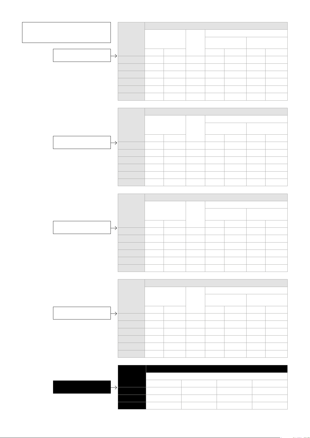
*Note! Minimum (Min) values may
be smaller without any picture
quality degradation.
Recommended bitrates
for H.264 encoding.
Recommended bitrates
for MPEG-4 encoding.
Resolution Bitrate (kbps)
Min* Max Recommended
Interlacing
toolsets OFF
CBR CapVBR CBR CapVBR CBR CapVBR
D1 1900 1900 5500 2500 2500 2800 2300
4CIF 1900 1900 5500 2500 2500 2800 2300
Half D1 1000 1000 3000 1400 1400 1700 1300
2CIF 1000 1000 3000 1400 1400
CIF 500 500 1700 650 650
QCIF 150 150 500 200 200
Resolution Bitrate (kbps)
Min* Max Recommended
Interlacing
toolsets OFF
CBR CapVBR CBR CapVBR CBR CapVBR
D1 2200 2200 6000 3500 3500 3200 3200
4CIF 2200 2200 6000 3500 3500 3200 3200
Half D1 1200 1200 3200 1900 1900 1800 1800
2CIF 1200 1200 3200 1900 1900
CIF 600 600 2000 1000 1000
QCIF 200 200 600 300 300
Interlacing
toolsets ON
Interlacing
toolsets ON
Recommended bitrates
for MJPEG encoding.
Recommended bitrates
for MPEG-2 encoding.
Resolution Bitrate (kbps)
Min* Max Recommended
Interlacing
toolsets OFF
CBR CapVBR CBR CapVBR CBR CapVBR
D1 6000 6000 12000 8000 8000 8000 8000
4CIF 6000 6000 12000 8000 8000 8000 8000
Half D1 3000 3000 6000 4500 4500 4500 4500
2CIF 3000 3000 6000 4500 4500
CIF 2000 2000 4500 2500 2500
QCIF 600 600 1300 750 750
Resolution Bitrate (kbps)
Min* Max Recommended
Interlacing
toolsets OFF
CBR CapVBR CBR CapVBR CBR CapVBR
D1 2500 2500 6600 4600 4600 4200 4200
4CIF 2500 2500 6600 4600 4600 4200 4200
Half D1 1300 1300 3500 2500 2500 2300 2300
2CIF 1300 1300 3500 2500 2500
CIF 700 700 2500 1300 1300
QCIF 200 200 600 350 350
Interlacing
toolsets ON
Interlacing
toolsets ON
Resolution Bitrate (Mbps)
Recommended
Recommended bitrates
for HD video encoding.
25 MPH200 series video encoders WebUI user manual
720p 4...5 4.6...5.8 8...10 12.6...15.8
1080i60 10...12 11.5...13.8 21...24 31.5...37.8
1080p30 10...12 11.5...13.8 21...24 31.5...37.8
H.264 MPEG-4 MPEG-2 MJPEG
Page 28
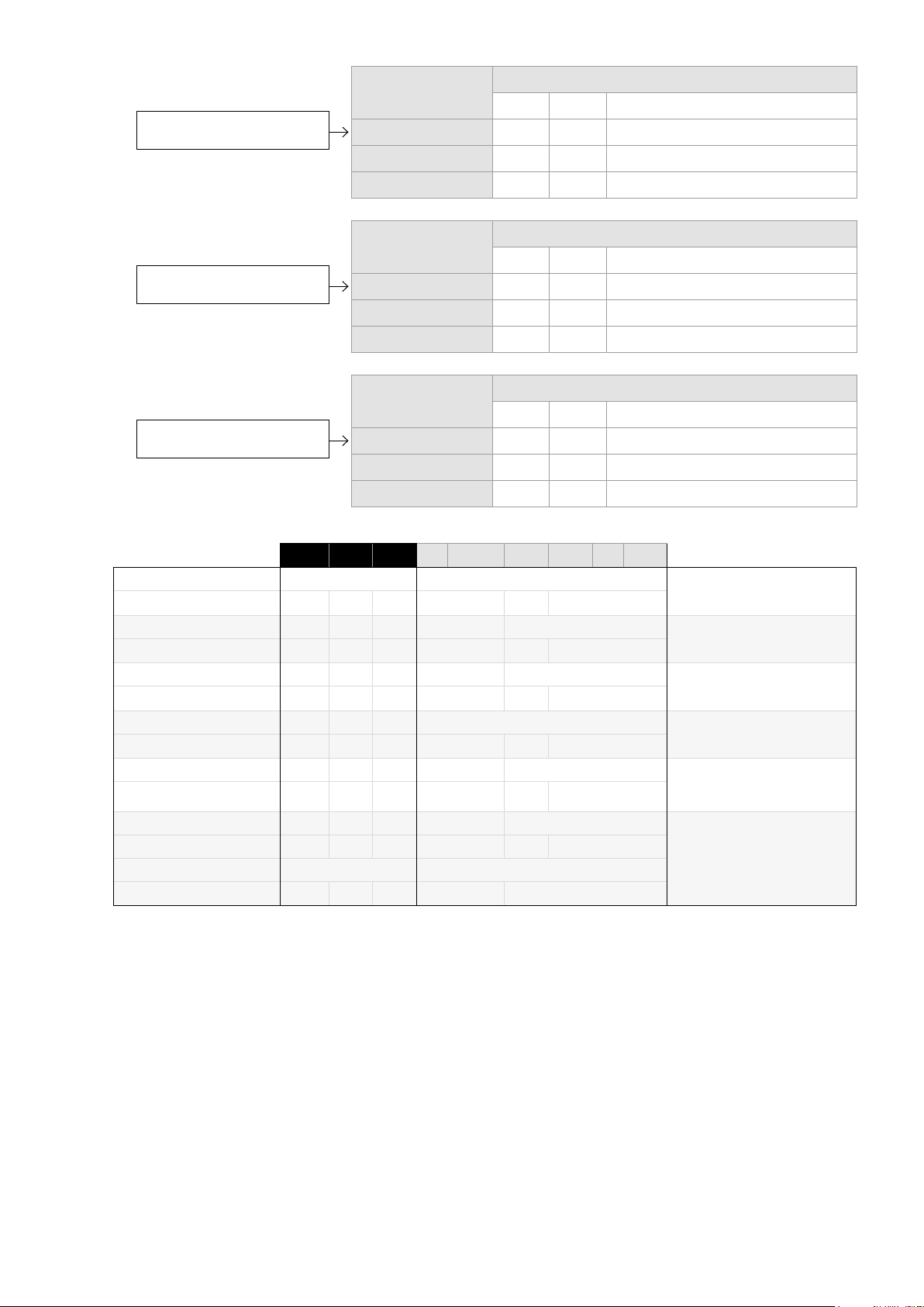
Recommended GOP sizes
for H.264 encoding.
Recommended GOP sizes
for MPEG-4 encoding.
Recommended GOP sizes
for MPEG-2 encoding.
Rate Control Mode GOP
Min Max Recommended
CBR 7 3000 60 -->
Capped VBR 7 3000 15 -->
VBR 7 3000 7 -->
Rate Control Mode GOP
Min Max Recommended
CBR 7 120 60...120
Capped VBR 7 120 15...120
VBR 7 120 7...120
Rate Control Mode GOP
Min Max Recommended
CBR 7 120 60...120
Capped VBR 7 120 15...120
VBR 7 120 7...120
Field Encoding
Deinterlacer
Field Encoding
Deinterlacer
Field Encoding
Deinterlacer
MBAFF
Deinterlacer
MBAFF
Field Encoding
Deinterlacer
Type eld value
Type specic eld values
1080p 1080i 720p D1 Half D1 4 CIF 2 CIF CIF QCIF
Not available Not available
x One eld used
na x na x Not available
x One eld used
x x
x One eld used
x One eld used
x x
x One eld used
x x
x One eld used
0 0
0 1 & 2 0 1 & 2 0
Supported interlace coding tools for the MPH video encoders.
H.264 Base Prole (BP)
Level 3
H.264 Main Prole (MP)
Level 3
MPEG-2 Main Prole (MP)
Main Level
MPEG-4 Simple Prole (SP)
Level 5
MPEG-4 Advanced Simple
Prole (ASP)
Level 5Deinterlacer
MJPEG
26 MPH200 series video encoders WebUI user manual
Page 29
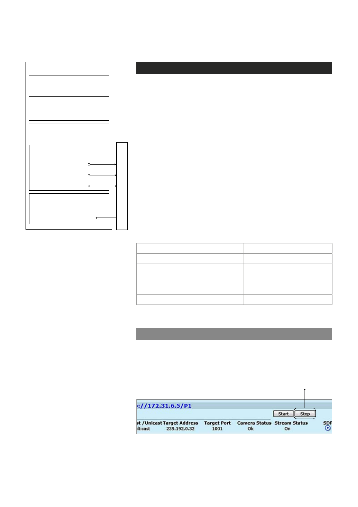
Conguring audio channels
MEDIA PROFILE
AUDIO INTERFACE
•
Balanced or unbalanced
AUDIO SOURCE
•
Fixed audio sources:
Mono 1, Mono 2, Stereo
AUDIO SINK
•
Audio sink naming
AUDIO ENCODER CONFIGURATION
•
Encoder type and parameters
•
Destination IP address
- primary stream
•
Additional IP address(es)
- stream multiplication
•
Dynamic streams (RTSP)
AUDIO DECODER CONFIGURATION
•
Decoder type and parameters
(samplerate same as in encoder)
•
Source multicast address/port
Streams (RTP)
Description how the audio encoder,
audio source, audio input and audio de-
coder is assembled to the media prole.
Audio connection
MPH200 encoder supports two bi-directional audio channels, which can
be used for one stereo audio or two mono audio purposes. The audio
interface supports both balanced (both channels separately) and unbal-
anced wiring. Audio input impedance is 6.6 kΩ in unbalanced mode and
13 kΩ in balanced mode. The device is capable of driving 0.707 Vrms
(single-ended output) / 1.414 Vrms (differential output) into a 10 kΩ load.
The audio channels operates independently, i.e. despite the absence of
all video signals.
Note! Physical audio interface is shared between audio interfaces, so audio interface mode (balanced/unbalanced) and
sampling rate congured to each used audio encoder and
decoder conguration must be equal.
Normally audio is transmitted and received in separate RTP streams.
However, if video stream is using transport stream (TS), audio packets
can be encapsulated inside the same video stream. Note that if audio
packets are encapsulated inside the video stream , MPH audio decoder
cannot decode it. Audio settings can be congured from web user interface (WebUI).
Pin Balanced signal Unbalanced signal
1 Audio in - GND for Audio 1 in
2 Audio in + Audio 1 in
3 GND (shield) GND
4 Audio out + Audio 2 out
5 Audio out - GND for Audio 2 out
Audio connector’s pinout.
Audio channel conguration
MPH is an ONVIF compliant device and audio channel encoder conguration is designed according to ONVIF standard. Audio decoder is
designed similarly but is not according to ONVIF standard.
Note! Before addinging the audio conguration to a video prole,
make sure that video stream is stopped on the MAIN page.
27 MPH200 series video encoders WebUI user manual
Page 30
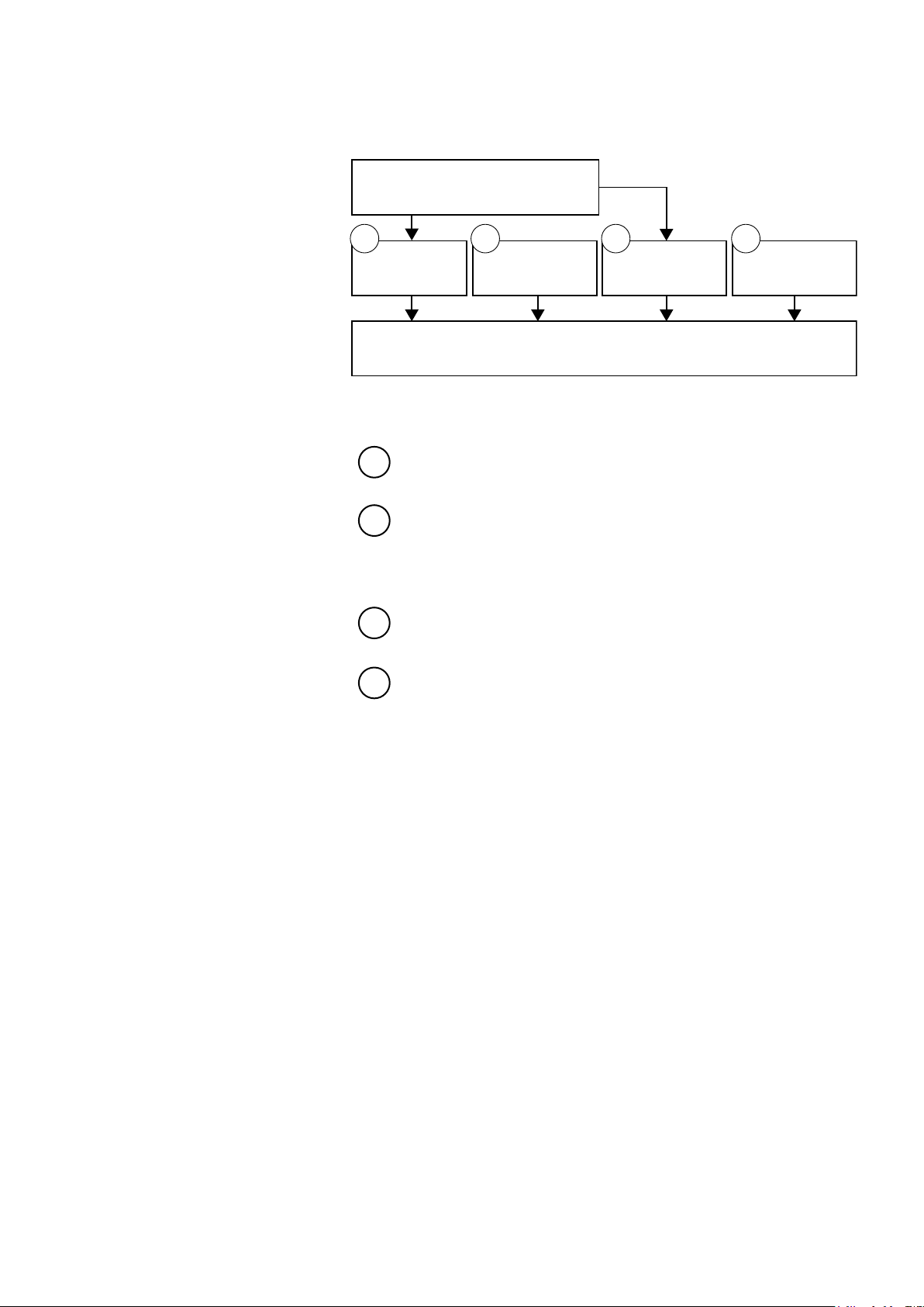
AUDIO INTERFACES
Balanced or unbalanced
1 2 3 4
AUDIO SOURCE
Stereo, Mono L/R
AUDIO ENCODER
Audio format
MEDIA PROFILE CONFIGURATIONS
(add audio to media profile)
Stereo, Mono L/R
AUDIO DECODERAUDIO SINKS
Audio conguration owchart.
Adding audio encoder to media prole:
1. Add to media prole (Media Conguration/Media Proles) desired
audio source conguration. Choises “Mono Audio In 1”, “Mono
Audio In 2”, “Stereo Audio In”.
2. Add to media prole desired audio encoder conguration (Media
Conguration/Audio Encoders). Choises are “Audio Encoder -
AAC-LC” and “Audio Encoder – G.711”.
Adding audio decoder to media prole:
3. Add to media prole (Media Conguration/Media Proles) desired
audio source conguration. Choises “Mono Audio In 1”, “Mono
Audio In 2”, “Stereo Audio In.
4. Add to media prole desired audio encoder conguration (Media
Conguration/Audio Decoders). Choises are “Audio Encoder -
AAC-LC” and “Audio Encoder – G.711”.
28 MPH200 series video encoders WebUI user manual
Page 31
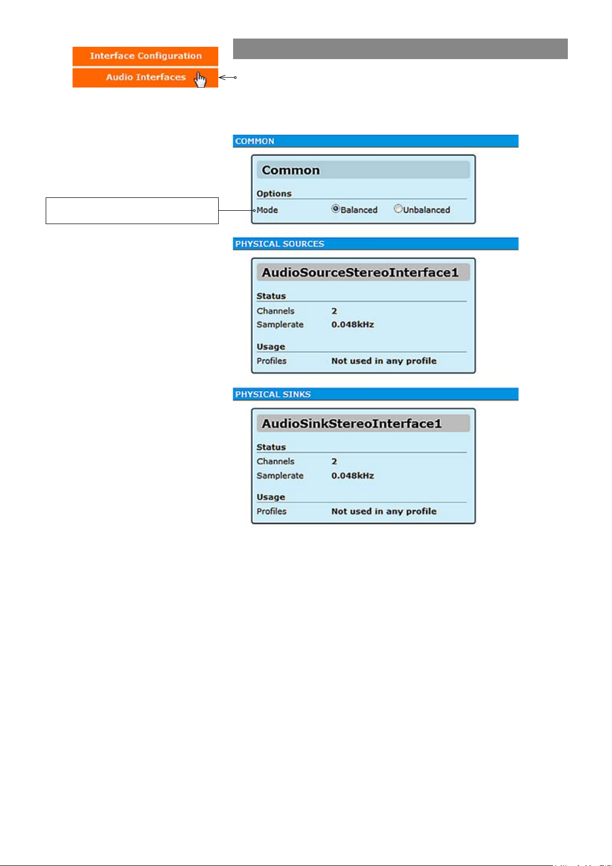
Audio interface mode selection. Affects
both input and output connection.
1. Audio interfaces
Click “Audio Interfaces” under the Interface Conguration menu. Audio
Interfaces page appears on the screen. In this page you can see the
number of physical audio inputs available and choose audio input mode
(balanced or unbalanced).
29 MPH200 series video encoders WebUI user manual
Page 32
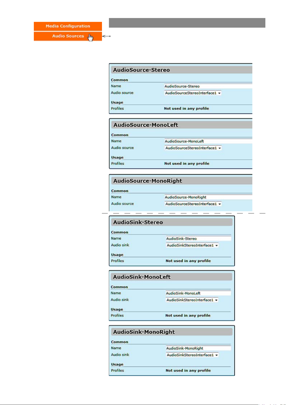
2. Audio source and sinks
Click “Audio Sources” under the Media Conguration menu. Audio
Source & Sink Congurations page appears on the screen. You can
rename the audio settings name but by default the name describes the
physical port location in connector, e.g.“Mono Audio In 1 (pins 1, 2)”.
30 MPH200 series video encoders WebUI user manual
Page 33
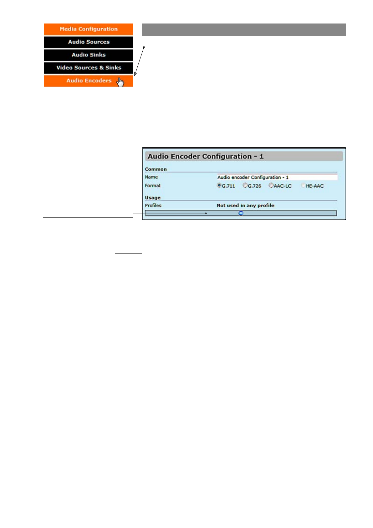
3. Audio encoders
Click “Audio Encoders” under the Media Conguration menu. Audio
Encoder Congurations page appears on the screen. Audio encoding
settings can be congured on this page, e.g. select format: G.711
(uLaw), G.726 (ADPCM), AAC-LC or HE-AAC, set samplerate, bit rate,
format and multicast IP/port settings for each prole.
This page contains (by default) four different customizable encoding
proles. This feature allows you to set four different audio encoding
combinations, each with their own settings.
On this page you can also add multiplied multicast/unicast streams from
each encoder.
Click this to see more settings.
Common
Name:
Format:
AUDIO ENCODER CONFIGURATIONS page.
_________________________________________________________
User dened alias name for
Audio format, either G.711, G.726, AAC-LC or HE-AAC.
audio prole (max 63 chars).
31 MPH200 series video encoders WebUI user manual
Page 34
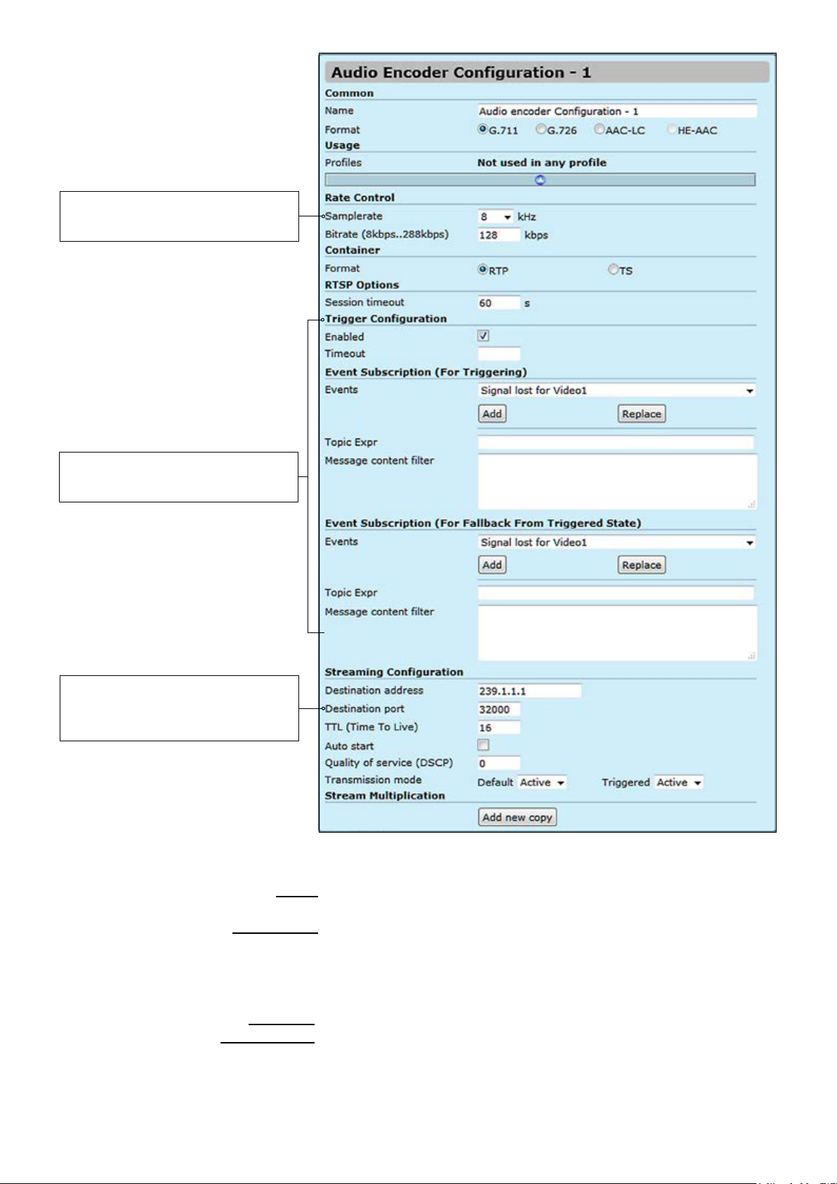
Note! Samplerate value has to be
same at both encoder and corresponding decoders.
Trigger Conguration
See section “Event management
system” from page 60 for more details.
Note! Only even port numbers can
be used for RTP, and then the
following odd port number shall be
used for RTCP (RFC 1889).
Usage
Proles:
Rate control:
Samplerate:
Bitrate:
Container:
RTSP Options:
Session tmeout:
AUDIO ENCODER CONFIGURATIONS page.
_________________________________________________________
Here you see how the media prole is assigned to a audio source.
_________________________________________________________
Denes audio codecs samplerate value (8/16/32/44.1 or 48 KHz). Setting a
higher samplerate value improves audio le quality and increases its size.
Denes
encoded audio bitrate (8..288 kbps). The higher the rate is, the
better the quality of sound is. However this also increases the le size.
RTP (Real-time Transport Protocol) or TS (MPEG transport stream).
_________________________________________________________
Timeout for RTSP session.
32 MPH200 series video encoders WebUI user manual
Page 35
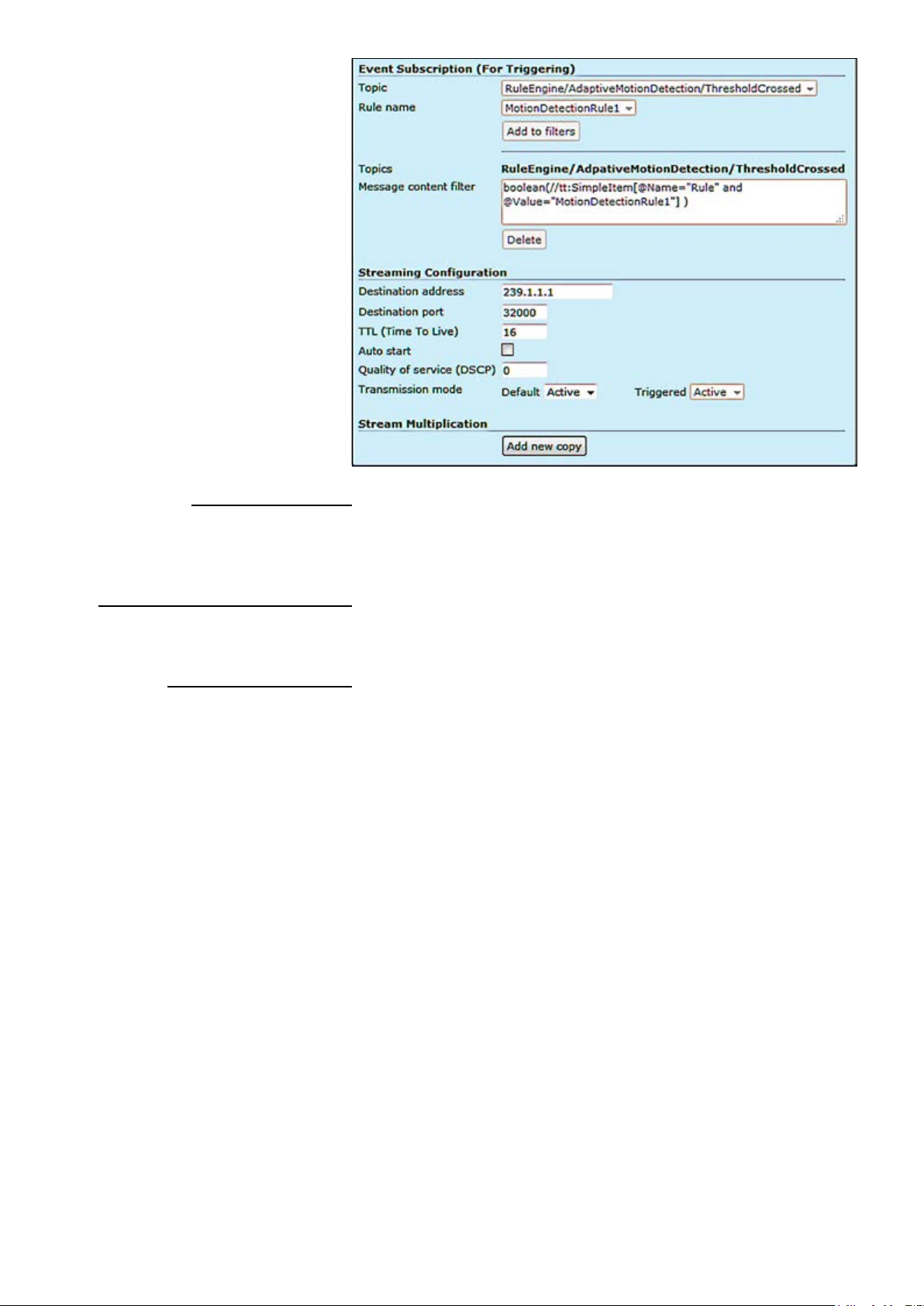
Trigger conguration:
Enabled:
Timeout:
Event subscription (for triggering):
Events:
Topic Expr:
Message content lter:
Streaming Conguration:
Destination address:
Destination port:
TTL (Time To Live):
Auto start:
Quality of Service (DSCP):
Transmission mode:
_________________________________________________________
Enables or disables the trigger feature
Keeps the event state unchanged for the dened period for instance if an
event clears quickly, it does not change its state for the dened timeout,
recommended 5 seconds.
_________________________________________________________
Select the event type
The topic expression of the event
Event description, lter and values
_________________________________________________________
Destination IP address. Multicast: Multicast IP address / multicast group.
This multicast IP address has to be same at both encoder and corresponding decoders. Unicast: IP address of receiving decoder.
UDP port number (0...65536). This number has to be same at both
encoder and decoder pairs. Port number needs to be even, as next odd
port is allways used for RTCP trafc.
Time-To-Live for video packets = number of hops that a packet is permitted to travel before being discarded by a router
(0...255)
.
Audio streaming will automatically start after reboot. Changing autostart
does not immediately start or stop streams.
(Differentiated Services Code Point) eld lets you set bits in the stream IP
header allowing a network device to apply rules such as how the packet is
forwarded in the network and QoS (Quality of service) management.
Default = Normal audio transmission mode:
Active: Audio is transmitted.
Paused: Audio encoder is ready but paused (no packets trasmitted).
Triggered = Audio is congured with triggering feature:
Active: Audio is transmitted.
Paused: Audio encoder is ready but paused (no packets trasmitted).
33 MPH200 series video encoders WebUI user manual
Page 36

Audio stream multiplication
Each audio encoding prole can be assigned with ve (5) different destination addresses (primary stream and additional streams). These addresses
can be freely set to unicast, multicast or a combination of these.
The use of multiple destination addresses up to a certain degree doesn’t
load the MPU; however one should take into account that the aggregate
bit rate of all output streams does not exceed the capacity of the
100Mbps interface.
Stream multiplication:
Destination address:
Destination port:
Quality of Service (DSCP/DiffServ ):
Transmission mode:
Destination IP address. Multicast: Multicast IP address / multicast group.
This multicast IP address has to be same at both encoder and
corresponding decoders. Unicast: IP address of receiving decoder.
UDP port number (0...65536). This number has to be same at both
encoder and decoder pairs.
Differentiated Services Code Point eld lets you set bits in the stream IP
header allowing a network device to apply rules such as how the packet is
forwarded in the network and QoS (Quality of service) management.
Active: Audio is transmitted.
Paused: Audio encoder is ready but paused (no packets trasmitted).
Adds new copy from stream.
:
34 MPH200 series video encoders WebUI user manual
Page 37
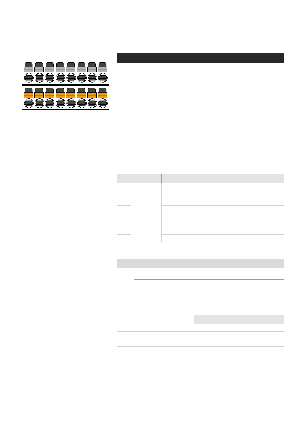
DATA 1 OUT+
DATA 1 OUT-
DATA 2 TX
DATA 2 RX
DATA 1 IN+
DATA 1 IN-
DATA 1 GND
DATA 2 GND
9 10
11
12 13 14 15 16
Conguring data channels
Data connections
The MPH200 encoder provides two independent bi-directional data
channels. Supported data modes for data channel 1 are RS422, RS485-
2w and RS485-4w. Data channel 2 is xed for RS232 mode only. Data
port settings can be congured from web user interface (WebUI) or
Command Line Interface (CLI).
1 2
4 5 6 7 8
3
Lower screw terminal connector on
front panel is used for data connections.
Data channel 1 is fully congurable and supports RS422, RS485 2-wire
and RS485 4-wire modes .ONVIF PTZ service is only available from
data channel 1, whereas data channel 2 is used either for RS232 data
mode or command-line interface usage. Both channels support tunnelling protocol and can be connected to the PTZ controller application.
The default factory settings are:
• Data channel 1: RS485-2w
• Data channel 2: mode is set to CLI (Command Line Interface) usage
Pin Signal RS232 RS422 RS485-2w RS485-4w
1
2
3
Data 1
4
5
6
7
Data 2
8
TX
RX
GROUND
OUT + OUT +
OUT - OUT -
IN + IN/OUT + IN +
IN - IN/OUT - IN -
GROUND GROUND GROUND
Data connector’s pinout and supported data types.
Led Colour Mode
Green
T
Blinking Green On stream.
Active Connection.
Terminal server TCP connection is established.
OFF / Dark No stream.
T - (terminal server) Led indicator operation. This LED indicates the
status of Terminal server activity on RS422/485 port.
Data 1 Data 2
Tunnelling protocol x
x
ONVIF PTZ protocol x
RS232
x
RS422, RS485 x
Command line interface
X
MPH unit provides two data channels for PTZ cameras on Terminal
server page.
35 MPH200 series video encoders WebUI user manual
Page 38
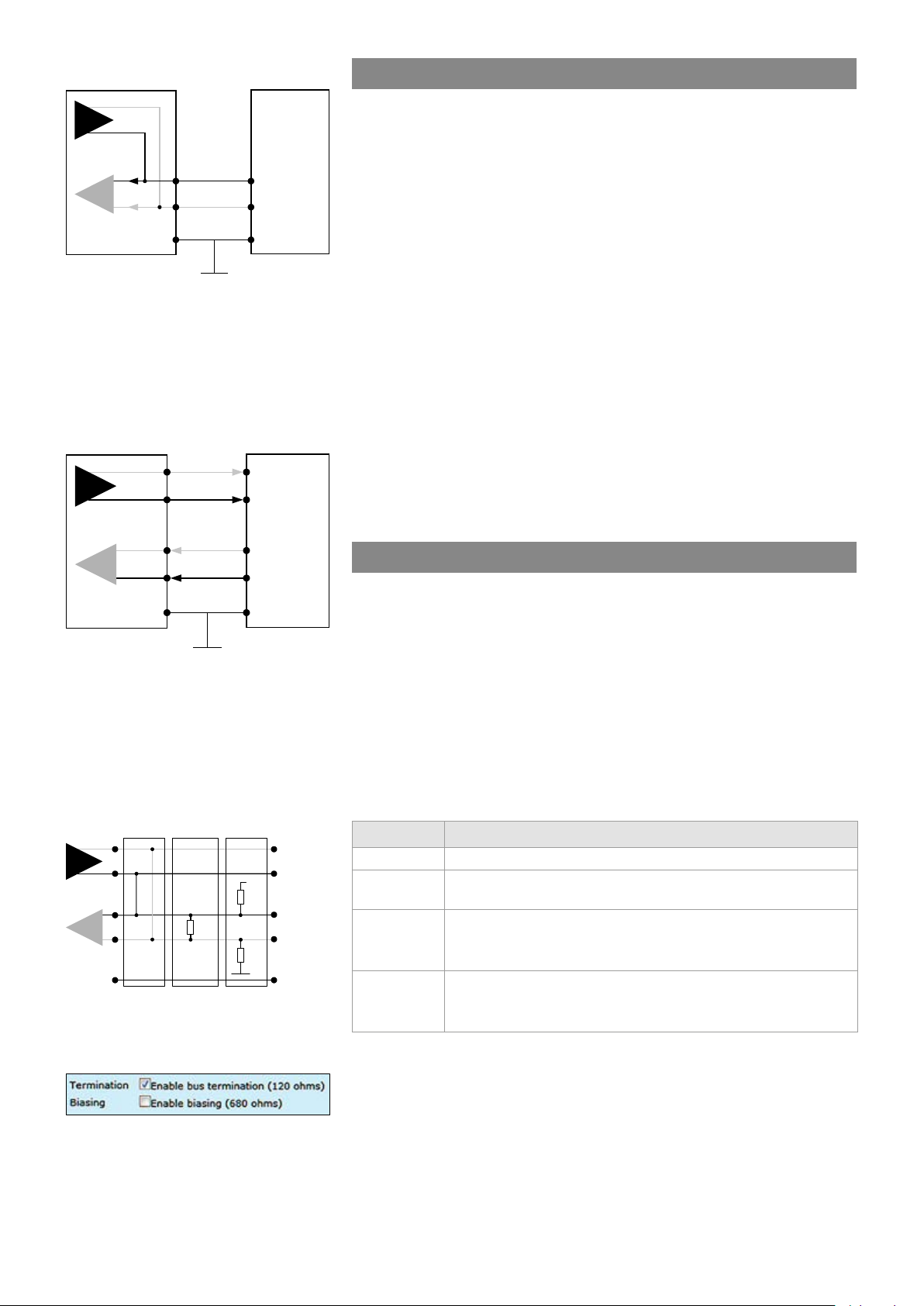
MPH Encoder
Slave
Tx
MPH Encoder
Slave
shield
DATA1 OUT+
Line
Line
RS485
Rx
Data type descriptions
-
Tx / Rx
+
DATA2 TX
6
+
7
-
DATA2 RX
8
DATA2 GND
+
-
Ground shield
RS232 is an unbalanced data format (i.e. the signal wire working
against a reference – ground). Simplex RS232 requires two connections
(signal and ground). Full-duplex RS232 requires three connections
(signal TX, signal RX and ground).
RS422 is a balanced data format. Simplex RS422 requires three data
connections (+/- and ground). Full-duplex RS422 requires ve data
connections (in+/in-, out+/out- and ground).
RS485-2w data connection diagram.
A 2-wire RS485 network is implemented
as a half-duplex system using single
twisted-pair cabling. This means that
data can ow in both directions but only
in one direction at a time.
+
Tx
-
+
Rx
-
DATA1 OUT+
1
DATA1 OUT-
2
3
DATA1 IN+
DATA1 IN-
4
DATA1 GND
5
+
Tx
-
+
Rx
-
Ground shield
RS422 / RS485-4w data
connection diagram.
A 4-wire RS485 network can be
implemented as a full-duplex system
using two twisted-pair buses where
each bus is used for each direction
of transmission.
RS485 is used for full-multipoint communications where multiple transceiver devices may be connected to a single twisted-pair signal cable.
Most RS485 systems use a Master/Slave architecture, where each
Slave unit has a unique address and responds only to packets
addressed to that unit. Packets are generated by the Master (e.g. CCTV
controller keyboard), which periodically ‘polls’ all connected Slave units
(e.g. CCTV camera receiver units). The Slave unit that has been
addressed then sends the appropriate reply packet back to the Master.
Slave units have no means of initiating communication without the risk
of a collision so they need to be assigned the ‘right to transmit’ by the
Master (by polling). RS485 exists in two versions, 2-wire and 4-wire.
Data termination and biasing
Termination is used to match impedance of a node to the impedance of
the transmission line being used. When impedance are mismatched, the
transmitted signal is not completely absorbed by the load and a portion
is reected back into the transmission line. If the source, transmission
line and load impedance are equal these reections are eliminated.
Biasing -> the lines will be biased to known voltages and nodes will not
interpret the noise from undriven lines as actual data; without biasing
resistors, the data lines oat in such a way that electrical noise sensitivity is greatest when all device stations are silent or unpowered.
Tx
MPH’s internal functionality for data
channel 1 termination and biasing.
Termination and biasing settings view
from WebUI.
36 MPH200 series video encoders WebUI user manual
Rx
Termination
2-wire
+
-
+
-
120Ω
Biasing
+5V
680Ω
680Ω
DATA1 OUT-
DATA1 IN+
DATA1 IN+
Ground
Data mode Input termination options
RS232 None
RS422
No term (with failsafe)
Line termination (120 Ω)
No term (with failsafe)
RS485 - 2w
Hard bias (forced 680 Ω line biasing)
Line termination (120 Ω)
No term (with failsafe)
RS485 - 4w
Hard bias (forced 680 Ω line biasing)
Line termination (120 Ω)
Data input termination options for data channels. Data termination
connects 120 Ω between pins. Hard bias connects 680 Ω (+input) to +5V
and GND (- input).
Page 39
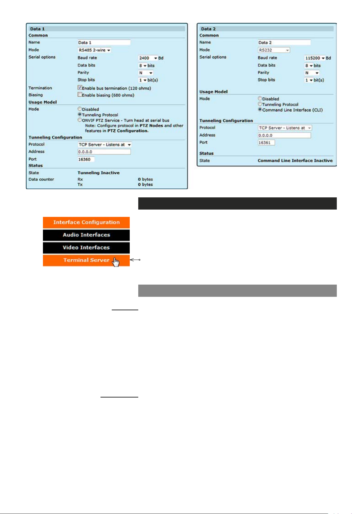
Data interfaces conguration
An analog PTZ camera can be controlled remotely over an IP network
via the MPH encoder’s serial port (RS-232/422/485). MPH encoders
supports two ways to control PTZ camera, ONVIF PTZ service and
transparent RS-data tunneling.
Click “Terminal Server” under the Interface Conguration menu.
Terminal Server - Data Ports page appears on the screen. Data port
settings can be changed on this page.
Data 1 & 2 (WebUI)
Common
Name:
Mode:
Baud rate:
Data bits:
Parity:
Stop bits:
Termination:
Biasing:
Usage Model
Mode:
_________________________________________________________
User dened alias name for
Data connection protocol towards the external device, options are
RS422, RS485 2-wire and RS485 4-wire (Data 1) and RS232 (Data 2)
Data channel connection speed (range 600...230 400 bps)
Number of data bits. Options are 5, 6, 7, 8 & 9
A data-checking technique, which uses an extra bit, Options are Even,
Odd & N (None)
Options are 1 or 2
Enabled/disabled (Data 1). The dafault setting is enabled.
Enabled/disabled (Data 1). The dafault setting is disabled.
_________________________________________________________
Data usage mode. By MPH encoder you can control PTZ cameras via
two protocols, Tunnelling Protocol and OnVIF.
data interface (max 64 chars)
37 MPH200 series video encoders WebUI user manual
Page 40

Data port mode can be set to the
tunneling protocol usage from the
Terminal Server page.
Tunneling protocol
Tunnelling Protocol enables you to establish point to point connection
between encoder, decoder and management system. There are three
options, TCP server, TCP client and UDP multicast.
Tunneling Conguration
Protocol:
Address:
Port:
Status
State:
Data counter:
_________________________________________________________
Client / server based connected is done by TCP client / server protocol. If
the encoder is set to be “TCP Server”, then the decoder or management
system must be set to “TCP Client”, or vice versa. In UDP multicast
mode, you can use a joystick to control multiple cameras and connection
can be point to multipoint.
Destination IP address
UDP port number (0...65535). This number has to be same at both encoder
and decoder pairs
_________________________________________________________
Shows data port’s state.
Note! In order to have correct channel status information, you can
check the followings:
• Device address is congured correctly in PTZ nodes page.
• Serial Port conguration : connection mode (RS-485 4-wire, etc),
Baud rate, and parity. in terminal server page.
• PTZ conguration is added to a media prole. PTZ conguration
“PTZ1” by default is added to media Prole 1.
Data port’s trafc counter.
38 MPH200 series video encoders WebUI user manual
Page 41
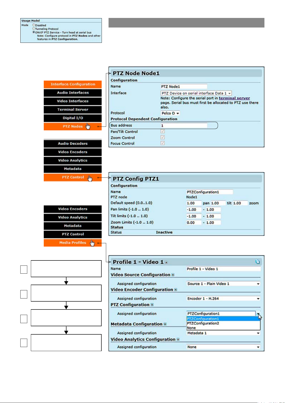
In order to activate the ONVIF PTZ
protocol, data port mode must be rst
set to the ONVIF PTZ service usage
from the Terminal Server page.
ONVIF PTZ service
ONVIF PTZ service lets you control the camera from ONVIF client
application. ONVIF PTZ service is available from data channel 1. It
means that MPH converts ONVIF PTZ commands to Pelco D
commands and transmits that to the camera via Data channel 1.
2. Next on the PTZ Nodes page you need to set a Bus address for the
camera, you can have two cameras using the same Data port with different
bus addresses.
TERMINAL SERVICE
1
2
3
4
Step-by-step owchart how to
congure ONVIF PTZ data 1 channel
in the MPH encoder.
(enable ONVIF PTZ on DATA 1)
PTZ NODE
(set a bus address for camera)
PTZ CONFIGURATIONS
(set limitations for PTZ operations)
MEDIA PROFILE
(PTZ configurations assignment)
3. Then on the PTZ congurations page you can set limitations for PTZ
operations. For each PTZ node you can limit speed, pan, tilt and zoom.
4. Finally on the Media proles page you need to assign the PTZ
conguration to the media prole where the camera is connected to.
39 MPH200 series video encoders WebUI user manual
Page 42
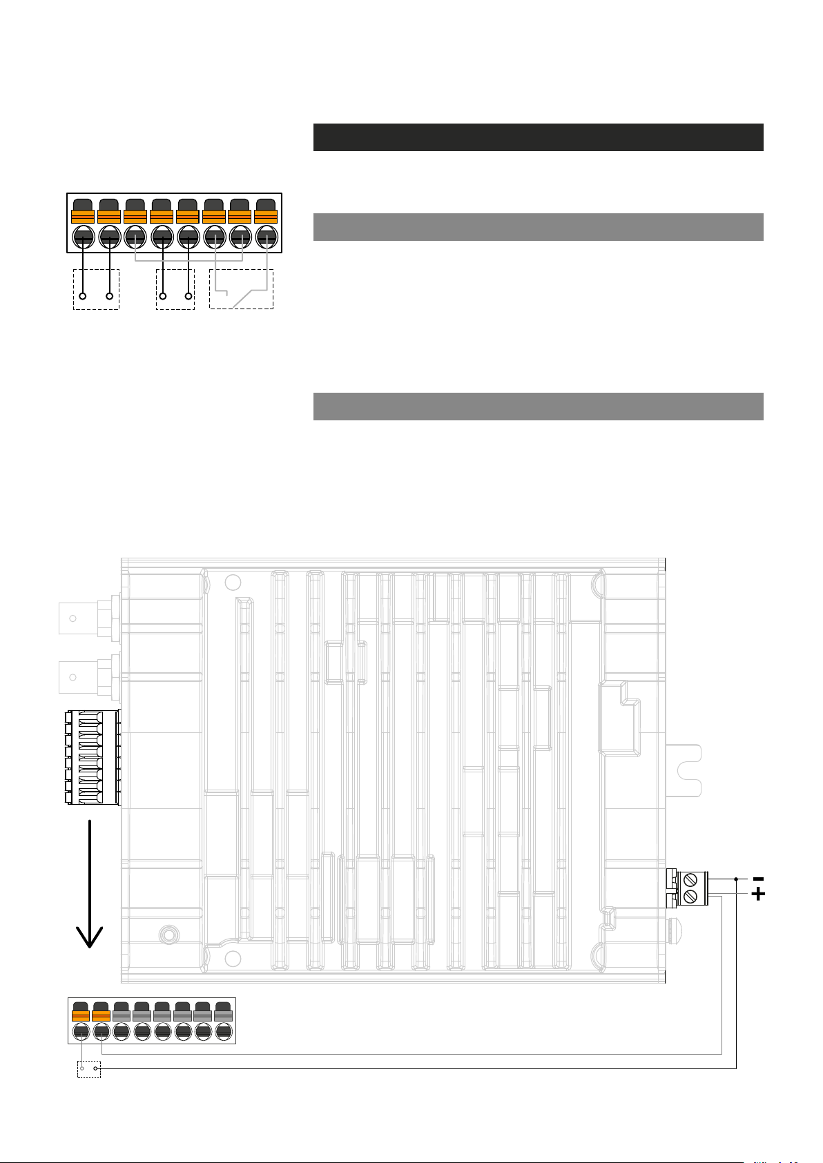
9 16
Vcc (10mA)
(+2.2...+30VDC)
(+12...24VDC)
Conguring contact closure channels
Contact closure loop (CCL) connection
OUTPUT
OUTPUT
Relay on/off
(30VDC/0.6A)
INPUT 1+
INPUT 1-
+ -
Current loop
logical 0
(0...+1.4VDC,
logical 1
INPUT GND
or
Short circuit
INPUT 2+
on/off
Upper screw terminal connector
(pins 9...16) on front panel is used
for contact closure connections.
INPUT 2-
The MPH200 series video encoders provide two inputs and one
contact closure output channel line.
Contact closure inputs
There are two different CC input connection types. First one is for a normal
short circuit which is called “dry contact closure”. Dry contact closure
enables you to switch ON & OFF input signals between connector’s
contact pins (internal power source). Second type is called “Optoisolated”
current loop input signals (logical 0 = 0.0VDC...+1.4VDC and logical 1 =
+2.2VDC...+30.0VDC) between contact pins (external power source).
Input pins nominal current consumption is 3 mA.
Contact closure output
CC output is a normal relay on/off - output signal (30V / 0.6A) between
connector’s contact pins.
Note! If voltage output is needed from output, do not use Vcc
(10mA) pin for it. Instead use external voltage source or device
power supply for it. See an example connection bottom.
OUTPUT
OUTPUT
9 16
Vcc out
40 MPH200 series video encoders WebUI user manual
Page 43
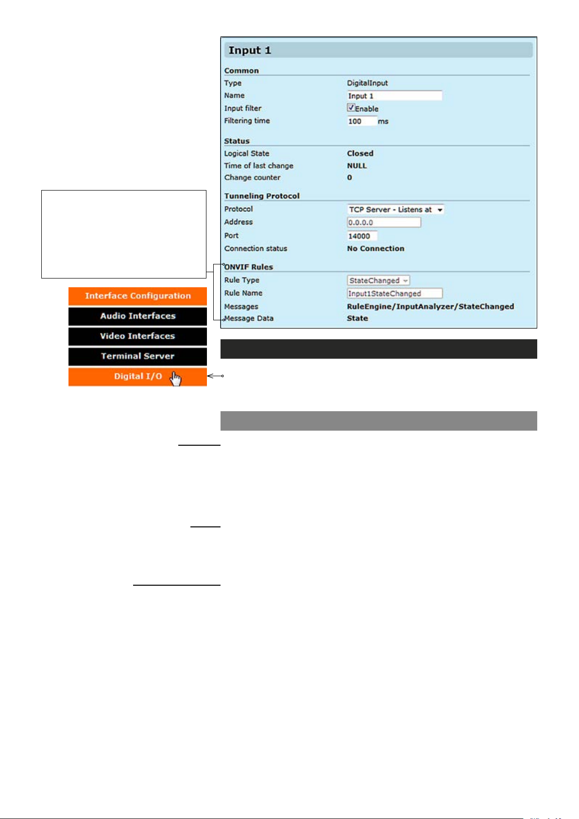
Device generates events from changes in digital input states. Events are
used internally to trigger conguration
changes in video encoding or provided
for ONVIF clients through metadata
streams and ONVIF notication interfaces (Real Time Notication Interface
and Base Notication Interface).
Contact closure interfaces conguration
Click “Digital I/O” under the Interface Conguration menu. Contact
Closure / Inputs & Outputs page appears on the screen. Contact
closure settings can be changed on this page.
Contact closure input 1 & 2
Common
Name:
Input lter:
Filtering time:
Status
Logical State:
Time of last change:
Change counter:
Tunneling protocol
Protocol:
Address:
Port:
Connection status:
_________________________________________________________
User dened alias name for
Monitors how many state changes happen (from close to open or vice
versa) during the time frame given by “Filter Time” parameter. If during
this time frame CC input state changes more than once, the input state
is set as “unstable”.
Time frame for “Input Filter” (100...2000 ms).
_________________________________________________________
The default state for CC input (open/closed)
Shows the time when the last cc state was changed.
Shows the total number of state changes that has been registered by a
given input CC.
_________________________________________________________
IP connection type. There are three options: “TCP Client - Connects to” ,
“TCP Server - Listens at” and “UDP multicast - Sends to”.
Destination IP address.
UDP port number (0...65535). This number has to be same at both encoder
and decoder pairs.
Shows connection status. The status can be active, disabled or
no connection.
contact closure interface (max 64 chars)
.
41 MPH200 series video encoders WebUI user manual
Page 44
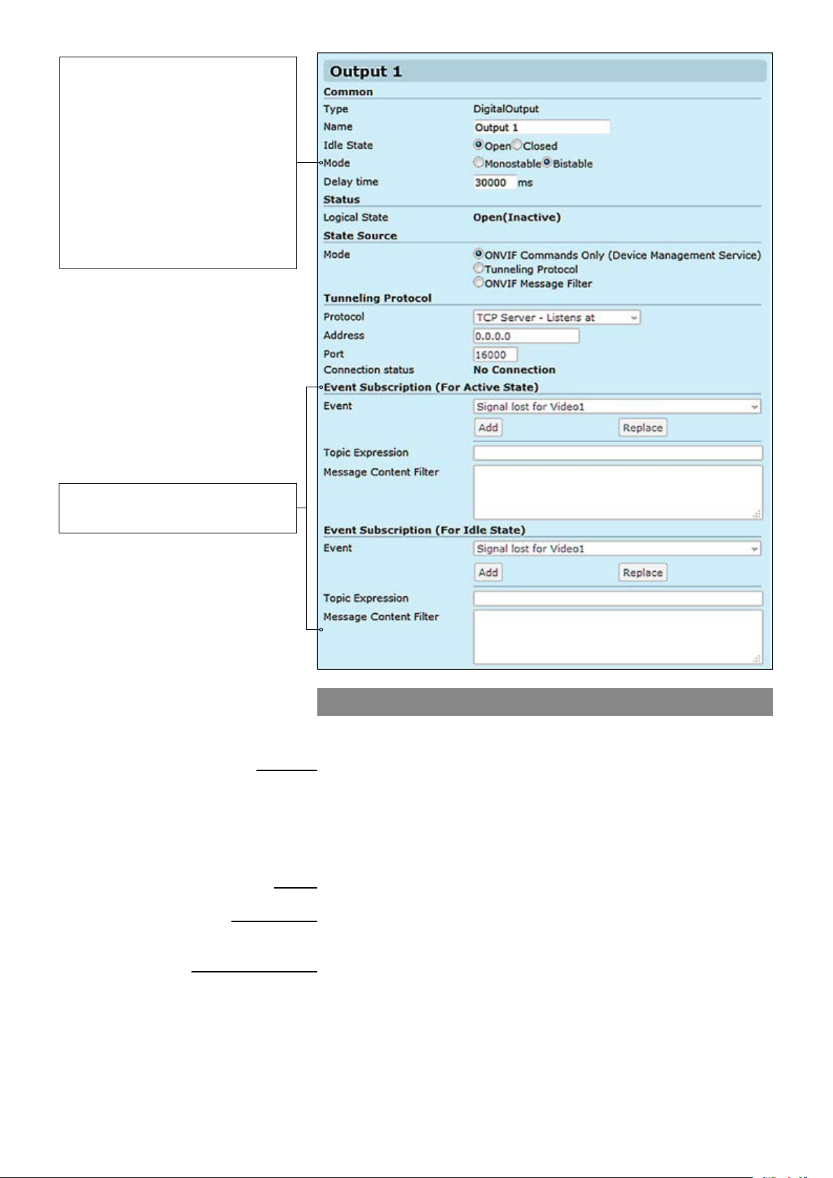
Bistable – After changing the state,
the relay remains in this state.
Monostable – After changing the
state, the relay returns to its idle
state after the specied time.
Note! When Contact closure
tunneling is used, Bistable mode is
only applicable. Monostable mode is
applicable when relay output is
controlled by ONVIF commands
from ONVIF client.
Trigger Conguration
See section “Event management
system” from page 60 for more details.
Common
Name:
Idle State:
Mode:
Delay time:
Status
Logical State:
State Source
Mode:
Tunneling protocol
Protocol:
Address:
Port:
Connection status:
Contact closure output
CC output can be controlled either with ONVIF Commands (SetRelayOutputState) or by receiving state using tunneling protocol.
_________________________________________________________
User dened alias name for
User dened default standby mode for contact closure output pins.
Open means that the output relay is open in inactive mode.
Close means the output relay is closed in inactive mode.
Contact closure output state mode, either Monostable or Bistable.
Time period in monostable mode when state changes back to the idle state.
_________________________________________________________
Current CC output state.
_________________________________________________________
Denition how to control the CC output. Options are:
ONVIF Commands only, Tunneling Protocol and ONVIF Message Filter
_________________________________________________________
There are three connection types. Point-to-point (Client/server) based
connection which is done by TCP client / server protocol. If the encoder is
set to be TCP Server, then the decoder or management system must be
set to TCP Client, or vice versa. In UDP multicast mode, you can control
multiple devices and connection can be point to multipoint.
Destination IP address
UDP port number (0...65535). This number has to be same at both encoder
and decoder pairs
Current CC connection status
contact closure interface (max 64 chars)
42 MPH200 series video encoders WebUI user manual
Page 45
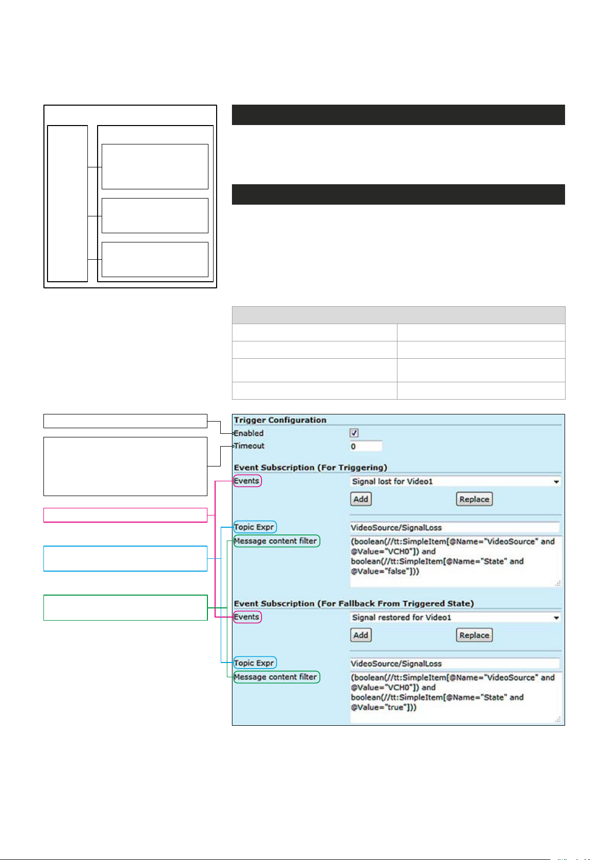
Event management
Triggering
Events Actions
Video
Changes video settings,
frame rate, bit rate and
video quality
Audio
Activates / deactivates
audio transmission
I/O (contact closure)
Changes the output
state in case of an event
Flowchart how MPH triggers actions
to different events.
General
MPH internally controls events as specied by ONVIF. Events are generated from digital IO inputs, motion detection, tampering detection and
video signal loss and each of those generate event with different topic.
Operation
MPH can trigger actions for video, audio and contact closers output.
These events are also available for video management system to trigger
congurable alarms. You can add multiples event at the same time and
each one triggers action.
Following events are available:
Event
Signal lost for video 1 and 2 Signal restored for video 1 and 2
I/O Inputs activation I/O Inputs deactivation
Motion Detection above the threshold
for video 1 and 2
Camera tampered Camera tamper removed
Motion Detection below the threshold
for video 1 and 2
Enables and disables the feature.
Keeps the event state unchanged
for the dened period for instance
if an event clears quickly, it does
not change its state for the dened
timeout, recommended 5 seconds.
Events: Select the event type.
Topic Expr: The topic expression
of the event.
Message content lter: Event
description, lter and values.
In addition to event topics, events contain data describing the event such
as the video interface related, amount of motion and threshold, etc.
The event data is available in the “Message Content lter” box, which is
XPath format for matching XML content. Triggering occurs when dened
“Topic expression” and “message content lter” matches the internal event.
43 MPH200 series video encoders WebUI user manual
Page 46
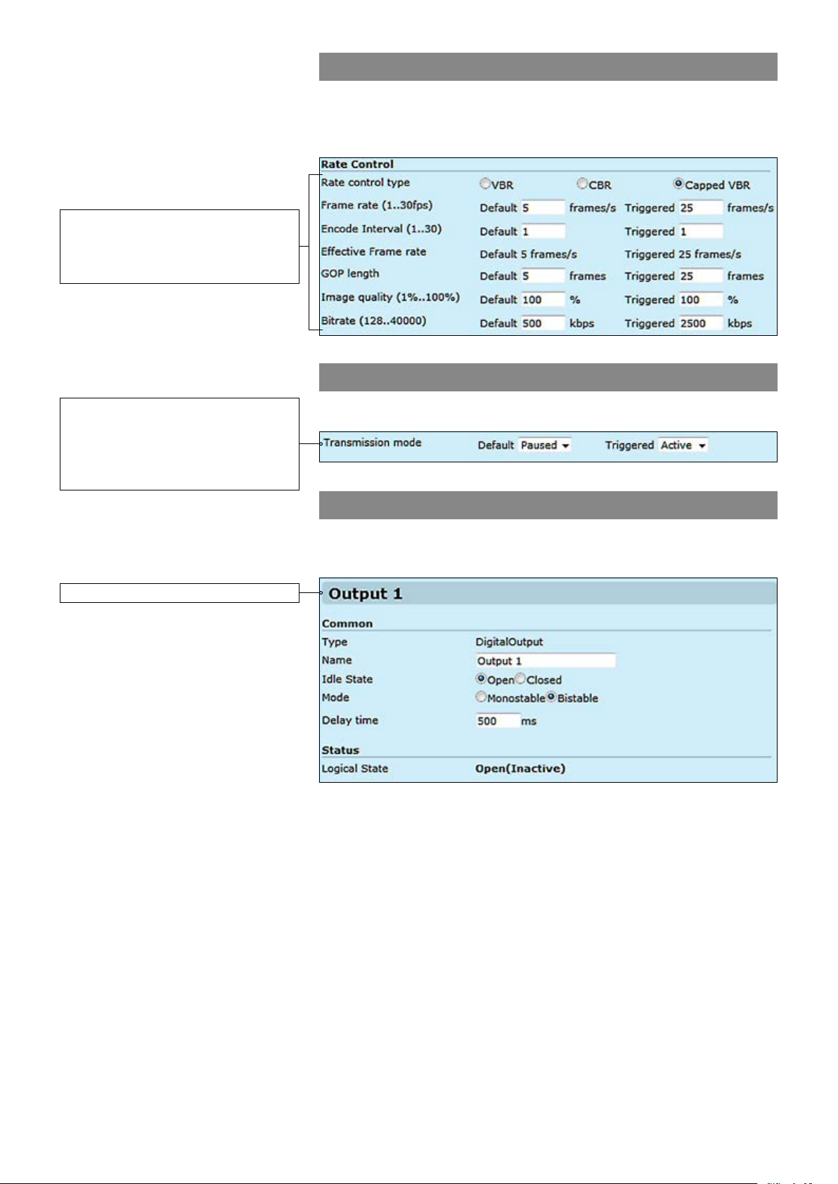
An example from Video Encoder
Congurations page shows:
The video bit rate and frame rate
change when an event triggered.
Video triggering
For video the triggering can trigger actions such as changing video
settings, frame rate, bit rate and video quality for each video prole
based on events.
Audio triggering
An example from Audio Encoder
Congurations page shows:
Audio stream is paused in normal
mode but when an event triggered,
it starts streaming.
An example from Digital I/O page.
For audio the triggering can activate or deactivate audio transmission.
Contact Closure triggering
For contact closure (digital I/O) the triggering changes the output state
in case of an event.
44 MPH200 series video encoders WebUI user manual
Page 47
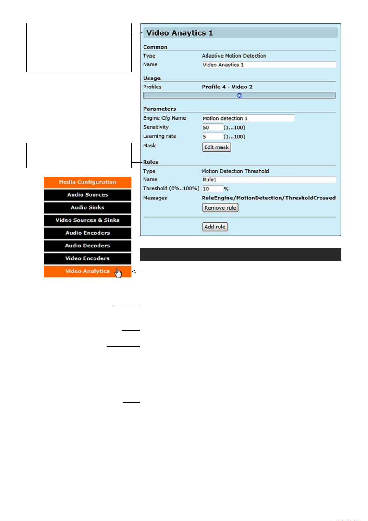
Video Analytics conguration is
activated if the conguration is included
in at least one of the proles.
Note! Prole does not need to be
activated when conguring video
analytics settings.
User can add/remove rules
(maximum of 5 rules are supported
per conguration).
Common
Type:
Name:
Usage
Proles:
Parameters
Engine Cfg Name:
Sensitivity:
Learning time:
Mask:
Rules
Type:
Name:
Threshold (0%..100%):
Messages:
Video analytics congurations
Click “Video Analytics” under the Media Conguration menu. Video
Analytics Congurations page appears on the screen. Video Analytics
settings can be congured on this page. All the parameters can be
congured dynamically i.e. when video analytics conguration is active.
_________________________________________________________
Adaptive motion detection.
User dened name for video analytics conguration object (max 64 chars).
_________________________________________________________
It shows the media prole which the video analytic is associated with .
_________________________________________________________
User dened name for video analytics engine conguration (max 64 chars).
Motion detection algorithm sensitivity. Range is 1-100%
Motion detection algorithm learning rate.
When monitoring an area for security, there may be certain parts within
the camera’s eld of view that need to be kept private. Masking is a
feature that enables these areas to be concealed from view.
_________________________________________________________
Motion detection threshold.
User dened name for
Threshold percentage to trigger rule. Range is 0-100%
rule (max 64 chars).
45 MPH200 series video encoders WebUI user manual
Page 48
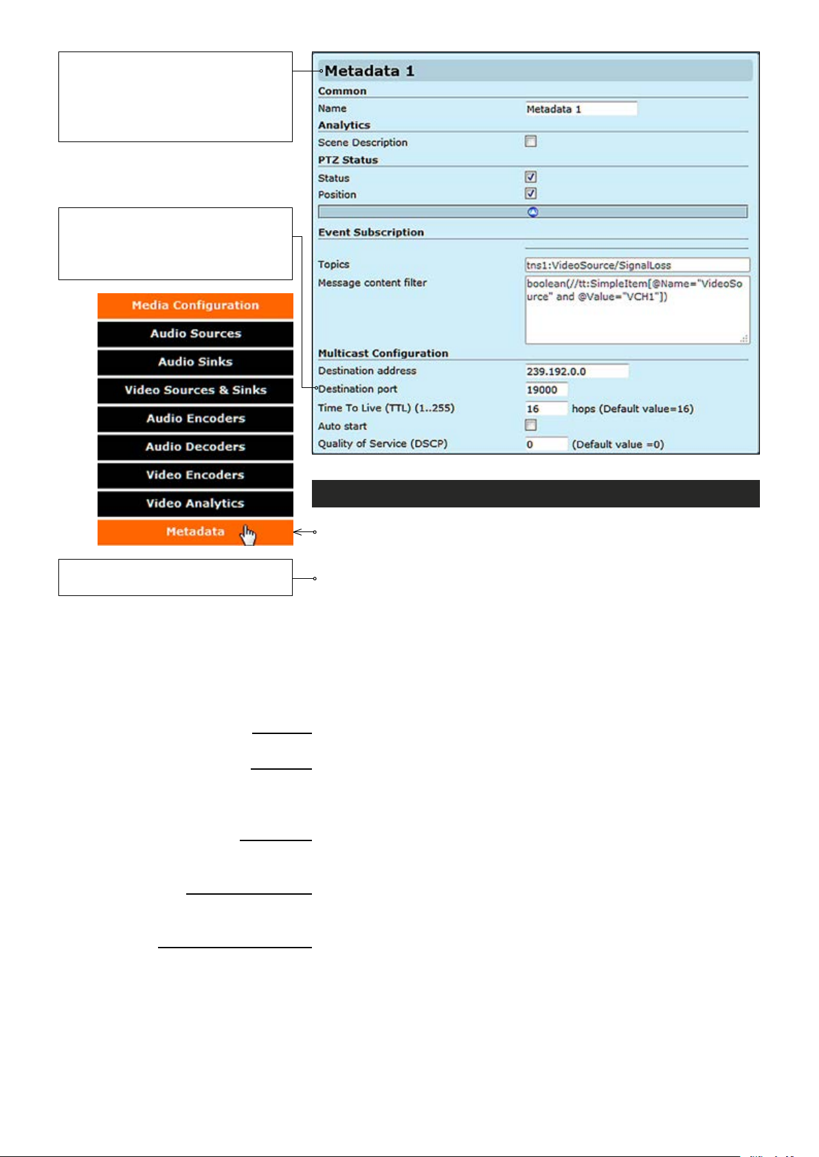
Metadata is a data channel and one
of the Onvif features which can carry
events, PTZ status, and/or video
analytics data for network video
devices.
Note! Only even port numbers can
be used for RTP, and then the
following odd port number shall be
used for RTCP (RFC 1889).
Metadata congurations
Click “Metadata” under the Media Conguration menu. Metadata
Congurations page appears on the screen. You can add a metadata
Note! Parameters cannot be
changed when streaming is active.
Common
Name:
Analytics
Scene Description:
PTZ Status
Status:
Position:
Event Subscription
Topics:
Message content lter:
Multicast Conguration
Destination address:
Destination port:
Time To Live (TTL) (1..255):
Auto start:
Quality of Service (DSCP):
46 MPH200 series video encoders WebUI user manual
conguration to an existing media prole, adding a metadata conguration
to a prole means that streams using that prole contain metadata. Four
metadata congurations are supported. In addition to video analytics
information, metadata can transmit PTZ camera status and position to the
Onvif client. Carrying other events such as “loss of video signal” is done by
metadata channel. Metadata transmits video analytics information like
motion detection over RTP stream in XML format. Currently MPH transmits
motion detection information, PTZ camera status (feedback) and video loss
event over metadata channel.
_________________________________________________________
User dened alias name for metadata conguration (max 64 chars).
_________________________________________________________
Enable/disable scene description. When enabled, adds video analytics
results from each analyzed frame to metadata. With motion detection this
includes amount of motion detected and dened threshold level.
_________________________________________________________
Enable/disable PTZ control status.
Enable/disable PTZ camera position.
Event subscription denes which events are included to metadata stream.
Event subscription topics.
Event subscription message content lter.
_________________________________________________________
You can set a multicast address and port number for a Metadata stream,
the multicast address can be the same as video stream multicast address
but with different port number.
Multicast Time-To-Live for metadata packets.
If enabled, metadata streaming starts automatically after reboot (does not
immediately start or stop streams).
Denes QoS class in differentiated services (DiffServ) trafc management.
DSCP/DiffServ (Differentiated Services Code Point) is a eld in the IP
headers that affects the priority of packet in the network per hop basis.
Page 49
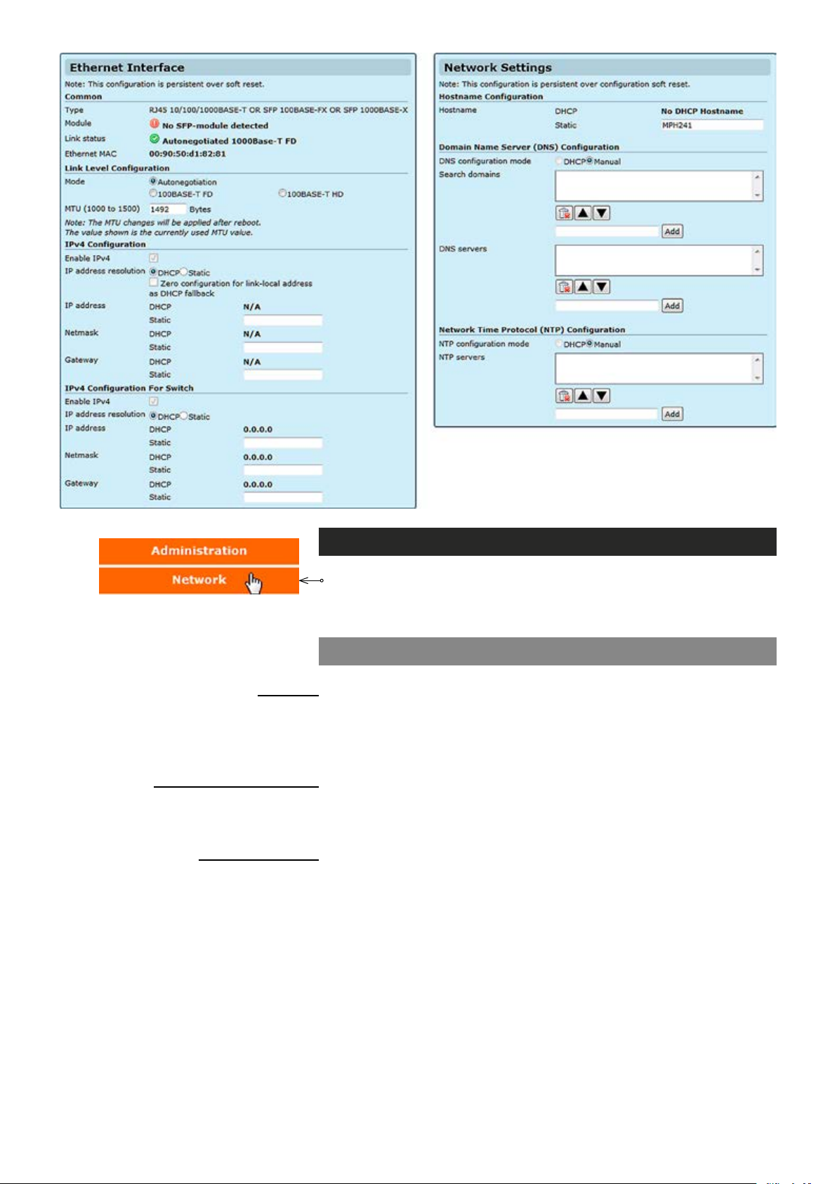
Network settings
Click “Network” under the Media Conguration menu. Ethernet Interface
& Network Settings pages appears on the screen.
settings
can be changed on thess pages.
Device’s network
Ethernet interface
Common
Type:
Module
Link status:
Ethernet MAC:
Link Level Conguration
Mode:
MTU (1000 to 1500):
IPv4 Conguration
Enable IPv4:
IP address resolution:
IP address:
Netmask:
Gateway:
_________________________________________________________
Device’s Ethernet Interface type
Shows the status of SFP module.
:
Shows the current link status and connection type.
MAC address of the device.
_________________________________________________________
You can select the connection mode, Auto negotiation or xed rate.
You can adjust he maximum transmission unit based on your connection
type, default value is 1492 bytes. The MTU range is from 68 to 1500.
_________________________________________________________
IPv4 enabled (change not supported).
You can set a static IP address for the unit (in case of static IP the user
can set IP address, subnet mask and gateway address) or select DHCP
mode to obtain IP address automatically. When you enable ZeroConf
protocol, the device will set an IP address randomly to itself if it fails to
nd the DHCP server after few trials.
IP address of the device.
Netmask address of the device.
Gateway address for router denition.
.
47 MPH200 series video encoders WebUI user manual
Page 50
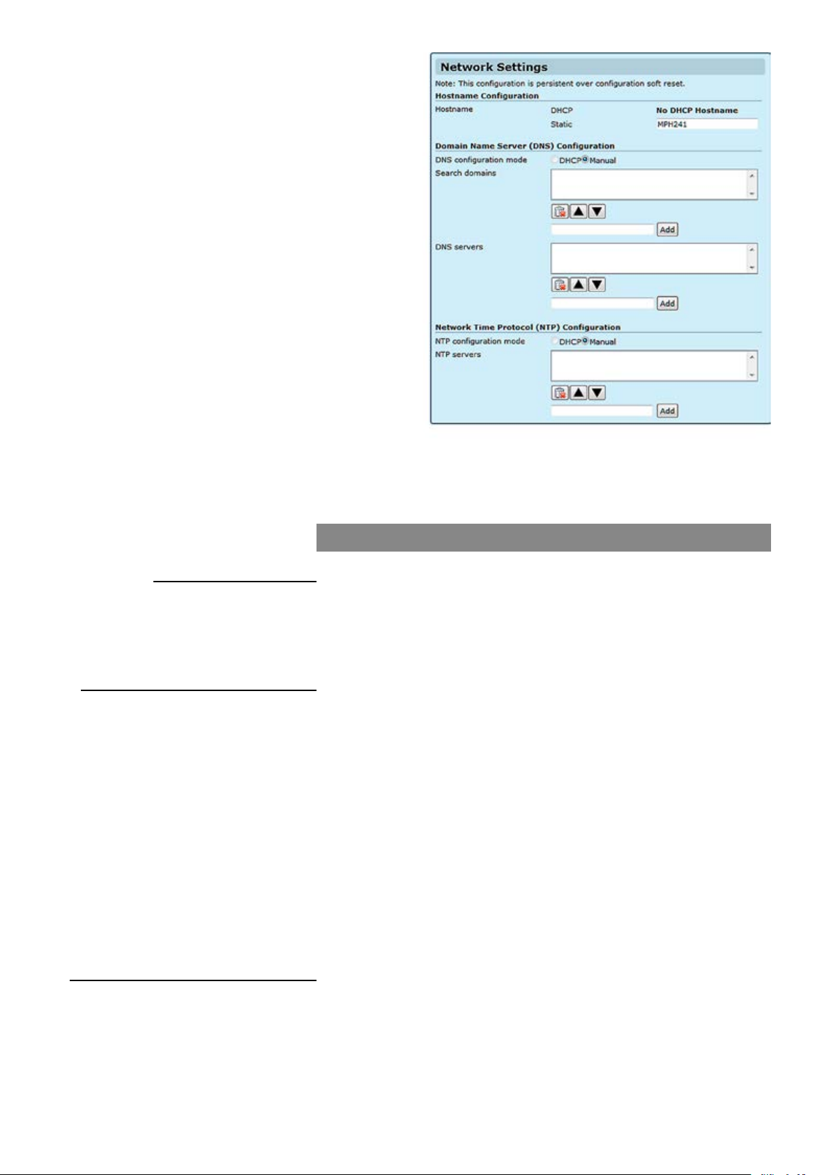
Network settings
Hostname Conguration
Hostname:
Domain Name Server Conguration
DNS conguration mode:
Search domains:
DNS servers:
Network Time Protocol (NTP) Conguration
NTP conguration mode:
NTP servers:
_________________________________________________________
User dened hostname for
device (max 64 chars). If the DHCP server is
congured to assign a hostname to the unit, it will be used, and will be
shown here.
Note! Underline is not allowed, use only marks A...Z, a...z, 0...9
and – (dash)
_________________________________________________________
If the unit needs to resolve an URL to an IP address by sending a name
resolution query, (for instance NTP server given in URL form from
DHCP) you need to enter at least one DNS server IP address.
Static Mode or DHCP Mode. In Static NTP mode you can set up to 3
NTP servers, change the priority by moving the servers up and down
and no needed servers can be deleted. The server on the top of the list
has the highest priority and decreases down the list. In DHCP mode all
controls are disabled and the priority is assigned by the DHCP server.
Searches the given DNS domain (e.g. teleste.com) for lookup an IP
address; you can add up to three domain names. You can change the
DNS domains’ priority by moving them up and down. The top of the list
has the highest priority.
Sends name resolution query to then given DNS servers, you can add up
to three DNS sever. You can change the DNS servers’ priority by moving
them up and down. The one on the top of the list has the highest priority.
_________________________________________________________
If you select DHCP server to control DNS and NTP settings, the manually entered DNS and NTP servers will be discarded.
You can add up to three NTP servers for time synchronisation. You can
change the NTP servers’ priority by moving them up and down. The one
on the top of the list has the highest priority.
48 MPH200 series video encoders WebUI user manual
Page 51
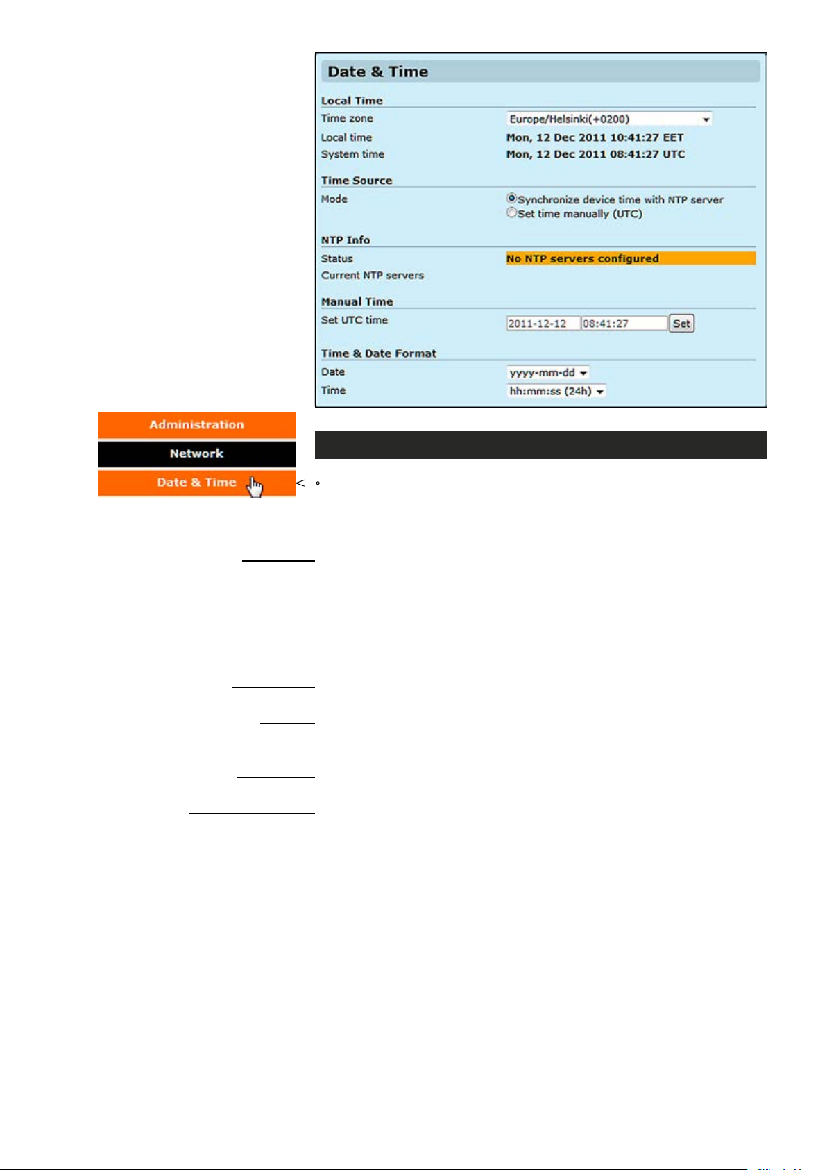
Local Time
Time zone:
Local time
System time:
Time Source
Mode:
NTP info
Status:
Current NTP servers:
Manual time
Set UTC time:
Time & Date Format
Date:
Time:
Date & time settings
Click “Date & Time” under the Administration menu. Date & Time
Settings page appears on the screen.
can be changed on this page. This page also shows the system time and
the local time calculated using the time zone set on the device.
_________________________________________________________
Selected time zone. Denes how conversion from system time (UTC) to
local time is done. For user the local time is shown, for example in video
text overlay timestamps. Conversion also takes daylight saving time in
to account.
:
Shows local time.
Shows system time (allways in GMT).
_________________________________________________________
Source for the clock, either manual or NTP synchronized.
_________________________________________________________
NTP status (synchronization OK, No NTP servers congured).
Shows congured NTP servers IP address.
_________________________________________________________
Set UTC time manually.
_________________________________________________________
Select date format type.
Select time format type.
Notes! If month is entered as 14, the date will change to February
of the next year and if date is entered as 32, the date will change
to the 1st of the next month if the number of days in the current
month is 31.
The date and time entered in the boxes has to match the format
specied. If the required date is 1st Jan 2011 , it has to be entered
as 01/01/2011 and not as 1/1/2011. The latter setting will throw up
an error when saved.
Device’s Date & Time settings
49 MPH200 series video encoders WebUI user manual
Page 52
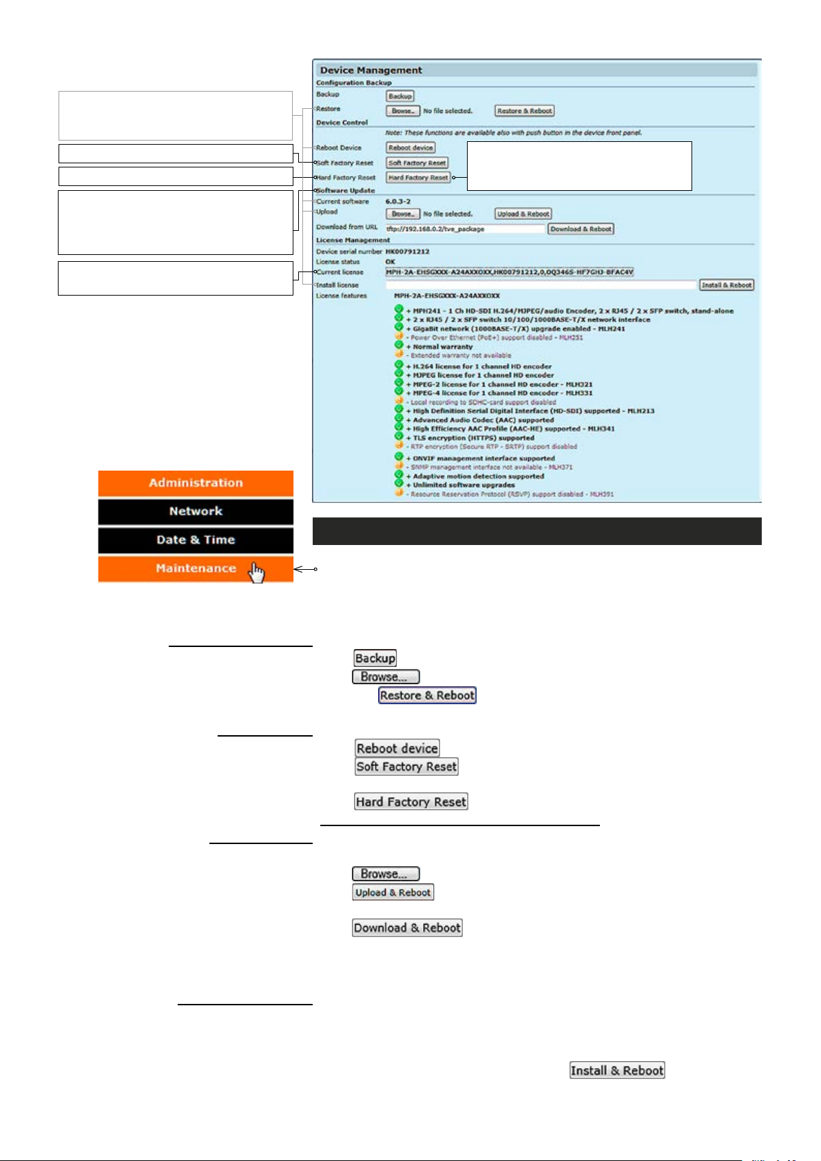
Note! After device reboots, wait until
M-led is green again (wait at least 10
minutes).
Note! wait at least 4 min. rebooting.
Note! wait at least 15 min. rebooting.
Note! After the software has been
updated, please clear your browser’s
cache to ensure the correct operation of WebUI.
Note! A new license will replace the
old one.
Note! Restores all setting to default
factory settings, including IP cong
and admin password to defaults.
Device management
Click “Maintenance” under the Administration menu. Device
Management page appears on the screen.
make conguration backup and restore, reboot the device, apply soft
and hard factory resets, update software and install new license key(s)
Conguration Backup
Backup:
Restore
Device control
Reboot Device:
Soft Factory Reset:
Hard Factory Reset:
Software update
Current software:
Upload:
Download from URL:
License management
Device serial number:
License status:
Current license:
Install license:
License features:
50 MPH200 series video encoders WebUI user manual
_________________________________________________________
Click ckup to store the current conguration to a le.
Click ckup to nd/select the stored conguration le to the device and
:
then click ckup to save the conguration le to the device.
Device restarts automatically after pressing this button.
_________________________________________________________
Click Reboot button to restart the device.
Click Reboot b utton to make a soft factory reset to the device ->
restores all, except IP conguration to the default factory settings.
Click Reboot b utto n to make a hard factory reset to the device ->
restores all settings to default factory settings!
_________________________________________________________
Shows device’s current rmware version.
Click ckup to nd/select the new rmware le to the device and then
click ck to upload the rmware le to the device. Device restarts
automatically after pressing this button.
Click ckup to upload the new rmware le from user specied
server (TFTP, FTP and HTTP) to the device. An example of FTP URL:
“tftp://FTP_SERVER_IP/MPH-x-x.x.xx-x.bin”. Device restarts automatically
after pressing this button.
_________________________________________________________
Shows device serial number.
Shows current licence status.
Shows device’s current licence(s).
Copy a licence code here and then click to take the
license to use.
Device restarts automatically after pressing this button.
This page allows you to
.
Page 53
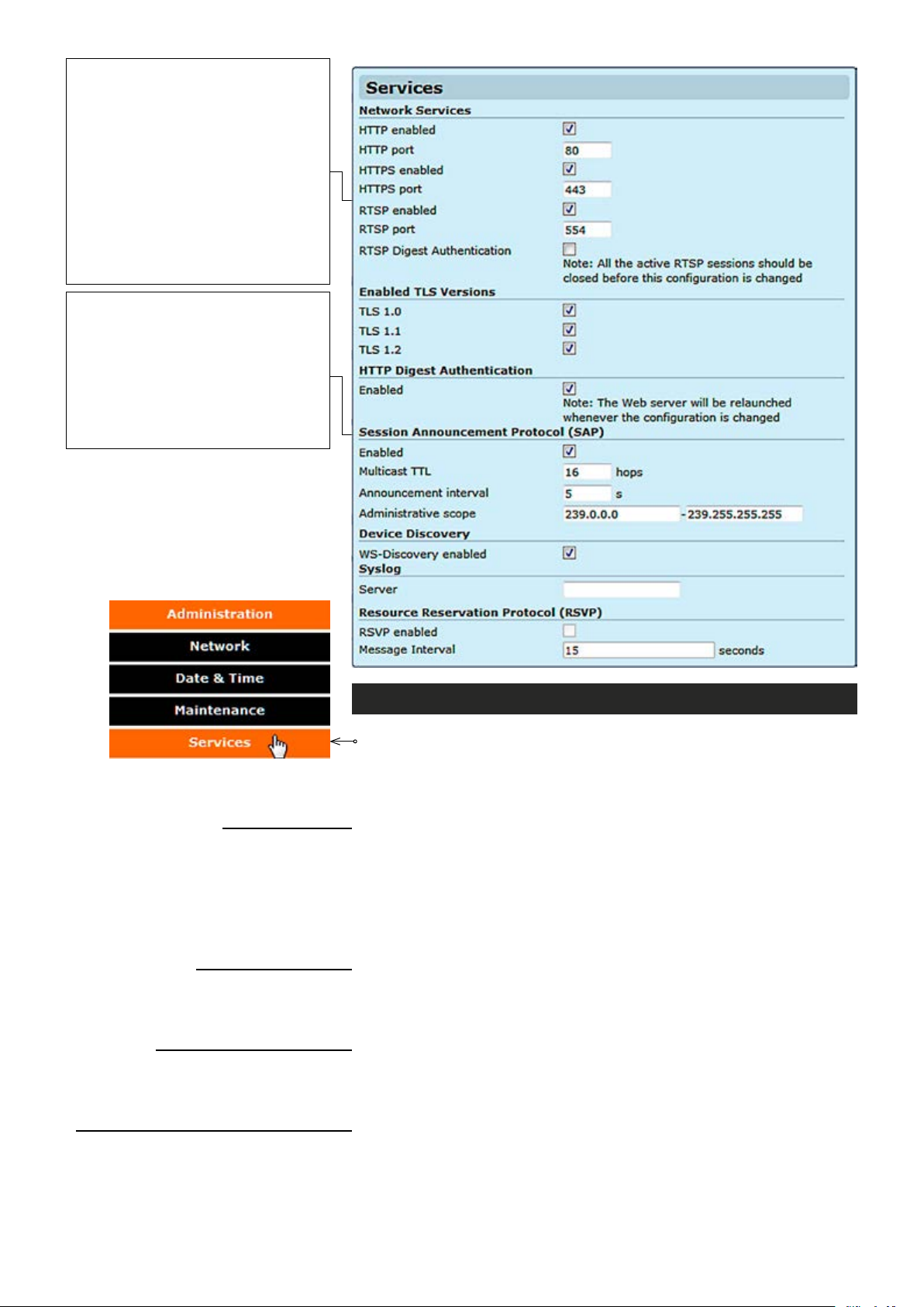
The Real Time Streaming Protocol
(RTSP) ia a network protocol used to
establish and control media sessions
between devices. For example, a video
Decoder sends RTSP play command
to the video Encoder.
Note! If port clash is detected while
conguring RTSP server port, device
gives an error message and disables
RTSP server. After that you have to
give an unused (valid) port and enable
RTSP server again.
Session Announcement Protocol (SAP) is a
protocol for broadcasting multicast session
information. A SAP listening application can
listen to the SAP multicast IP address and
construct a guide of all advertised multicast
sessions (RFC 2974). SAP uses Session
Description Protocol (SDP) as the format of
the session descriptions. Announcement
data is sent using IP multicast and UDP.
Network Services
HTTP enabled:
HTTP port
:
HTTPS enabled:
HTTPS port
:
RTSP enabled:
RTSP port
:
Enabled TLS versions
TLS 1.0:
TLS 1.1:
TLS 1.2:
HTTP Digest Authentication
Enabled:
Session Announcement Protocol (SAP)
Enabled:
Multicast TTL:
Announcement interval:
Services settings
Click “Services” under the Administration menu. Services Settings
page appears on the screen. This page allows you to enable/disable
different network services available and congure following parameters
of services:
_________________________________________________________
HTTP is always enabled.
Port 80 is used always.
Enable/disable HTTPS.
Congure HTTPS server port.
Enable/disable RTSP (Real time streaming protocol) server.
Congure RTSP server port.
_________________________________________________________
Enable/Disable Transport Layer Security protocol 1.0 (RFC 2246).
Enable/Disable Transport Layer Security protocol 1.1 (RFC 4346).
Enable/Disable Transport Layer Security protocol 1.2 (RFC 5246).
_________________________________________________________
Enable/Disable HTTP digest access authentication (RFC 2069).
Note! When is enabled, authentication is mandatory for all prole
based JPEG snapshot download.
_________________________________________________________
Enable/Disable Session Announcement protocol (RFC 2974).
Multicast Time-To-Live for SAP packets (1...255).
SAP timing in seconds (1...999). Retransmit time of SAP-packet. This
time has to be same at both encoder and decoder pairs.
51 MPH200 series video encoders WebUI user manual
Page 54
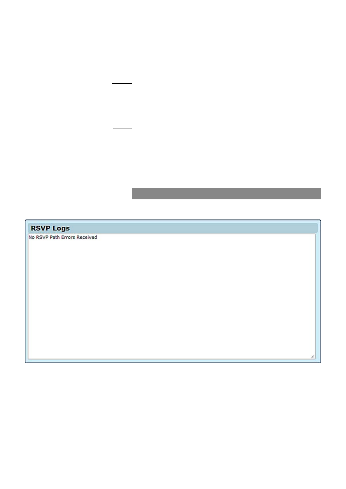
Administrative scope:
Device Discovery
WS-Discovery enabled:
Simple Network Management Protocol
(SNMP)
SNMP v2c enabled:
Read community:
Write community:
Trap destination 1...4:
Syslog
Server:
Resource Reservation Protocol (RSVP)
RSVP enabled:
Message Interval:
Range of multicast IP addresses advertised with SAP. When the stream
multicast address is within the SAP scope, end of the scope is used.
Otherwise default SAP-address 224.2.127.254 is used. Default SAPscope is 239.0.0.0 - 239.255.255.255.
_________________________________________________________
This enables ONVIF device discovery feature.
Currently this service is not upported.
Enable/Disable SAP SNMP v2c protocol. Requires licence MLH371
installation. Activation disables ONVIF.
Species the read only community (public or private).
Species the write community (public or private).
Trap Destination denes the IP address of an agent receiving traps.
_________________________________________________________
Syslog is a standard for computer data logging. By using syslog you can
collect messages sent from MPH on the syslog sever.
Shows syslog server IP address. If this eld is left blank then remote
logging is disabled.
_________________________________________________________
This enables RSVP feature (RFC 2205).
Denes RSVP message interval.
RSVP logs
Shows RSVP Logs.
52 MPH200 series video encoders WebUI user manual
Page 55
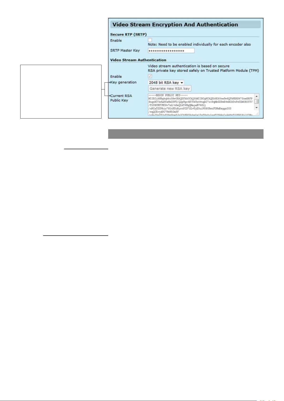
RSA involves a public key and a
private key. The public key can be
known to everyone and is used for
encrypting messages. Messages
encrypted with the public key can only
be decrypted using the private key. The
public key for the RSA algorithm are
generated by MPH key generator and
appears in the “Current RSA Public
Key” box.
Video stream encryption and authentication
Secure RTP (SRTP)
Enable:
SRTP Master Key
Video Stream Authentication
Enable:
Key generation
Current RSA Public Key
MPH200 series supports video stream encryption and authentication, it
adds authentication information to video elementary stream.
It allows verifying the exact encoder has encoded the video stream and
video is authentic. Authentication is done by a hardware chip in the device
called trusted platform module (TPM). TPM is a hardware chip in devices
that securely holds RSA key and generates RSA-signatures by it.
You can have a certication (x509) for TPM RSA key pairs (e.g. signed by
Teleste) mapped to the serial number of the MPH encoder, showing that
particular device encoded the video. So any recording can be traced back
to exact MPH unit.
Enables/disables SRTP feature.
A single “master key” can provide keying material for encryption and
:
integrity protection for both SRTP and SRTCP streams.
Video stream authentication is based on secure RSA private key stored
safely on Trusted Platform Module (TPM). SRTP uses 2048bit RSA
mode encryption for authentication. RSA delivers a higher level of
security strength compared to other algorithms.
Enables/disables video stream authentication feature.
:
Generates RSA key.
:
Shows
generated RSA public key.
53 MPH200 series video encoders WebUI user manual
Page 56
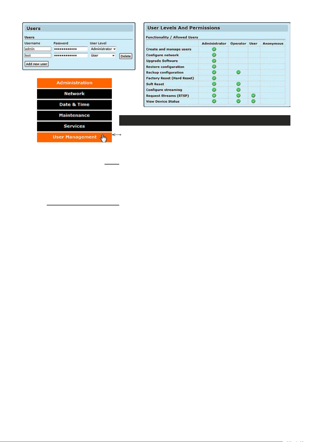
User management
Click “User management” under the Administration menu. User
management page appears on the screen.
user settings.
This page allows you modify
Users
Username:
Password
User Level:
Functionality / Allowed users
_________________________________________________________
Shows device user accounts. All user accounts are protected by a user
name and a password. Administrator user can create and remove user.
Set username for user.
Set password for user.
:
Select user level for user.
_________________________________________________________
Shows permissions for different users.
54 MPH200 series video encoders WebUI user manual
Page 57
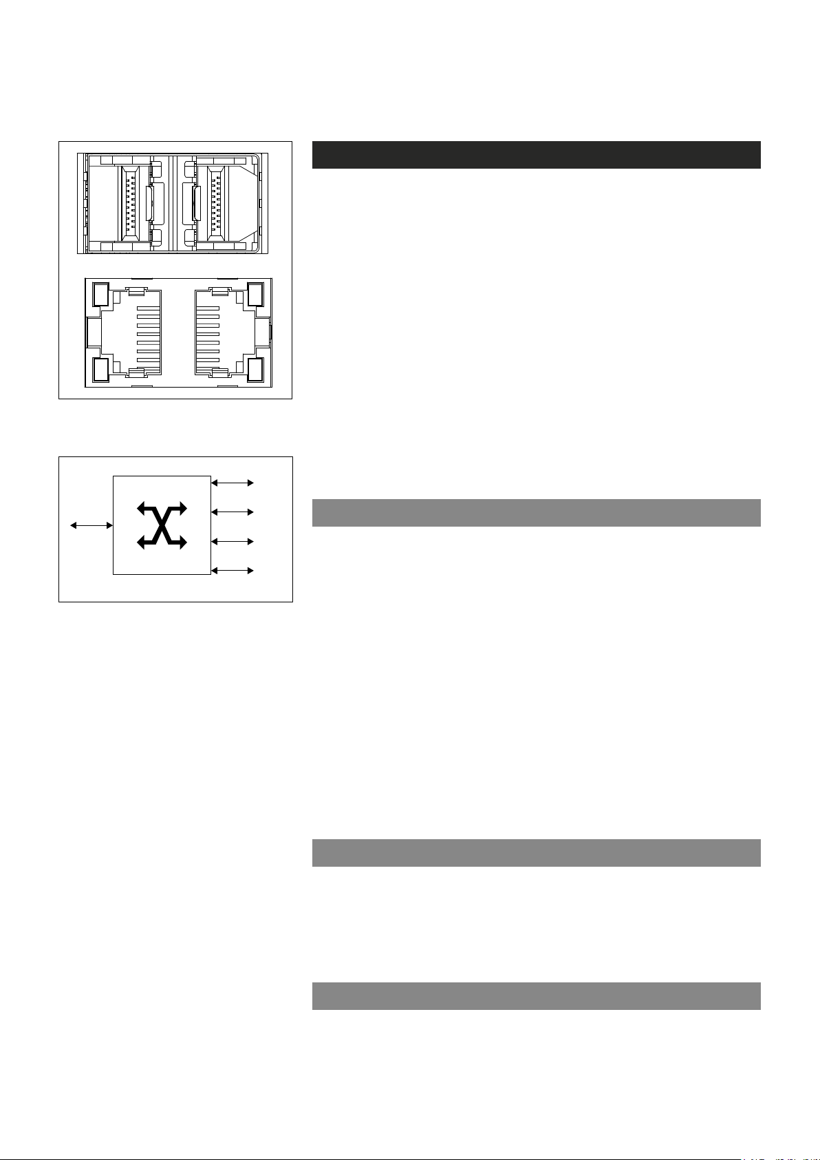
Conguring ethernet switch
1 2
3 4
SWITCH
(internal)
Port 1 (SFP)
Port 3 (RJ-45)
Port 4 (RJ-45)
Switch inroduction and features
MPH200 has a built-in four port tri-speed Ethernet Switch with two
integrated copper transceivers and two SFP ports. Switch is a fully
managed eld hardened stand-alone Gigabit Ethernet switch for video
networking applications. The product is designed for use in harsh
environment applications.
MPH200 Ethernet Switch provides non-blocking wire-speed performance. It can operate as either a VLAN-aware switch or a VLAN-unaware switch. It can forward frames at Layer 2, based on information
from layer 2 and layer 3. All memory is included on-chip, because each
port has its own shared memory of 20 kilobytes for frame storage. This
section gives an overview of the functionality and features of the switch.
MPH200 has two xed (3 &4) and two
SFP (1 & 2) Ethernet ports.
Port 2 (SFP)
Encoder
MPH200 switch’s internal connection.
MPH200 Ethernet Switch supports IGMP snooping, VLAN, network
redundancy, SNMP management, port conguration, port alarms, QoS
(layer 2 and 3) and port mirroring. Switch supports both command line
interface (CLI) and WEB User Iinterface (WebUI).
Auto-negotiation
MPH200 Ethernet Switch supports twisted pair auto-negotiation, as
dened in IEEE Std 802.3-2002 clause 28. The purpose of auto negotiation is to allow a device to advertise modes of operation. The auto
negotiation function provides the means to exchange information between
two devices that share a point-to-point link segment, and to automatically
congure both devices to take maximum advantage of their abilities. Auto
negotiation is performed totally within the physical layers during link
initiation, without any additional overhead to either the MAC or higher
protocol layers. Auto negotiation allows the ports to do the following:
• Advertise their abilities
• Acknowledge receipt and understanding of the common modes of
operation that both devices share
• Reject the use of operational modes that are not shared by
both devices
• Congure each port for the highest-level operational mode that both
ports can support.
55 MPH200 series video encoders WebUI user manual
Auto MDI/MDI-X function
The device automatically detects whether the cable connected to an
RJ-45 port is crossed or straight through, when auto-negotiation is
enabled. Standard wiring for end stations is Media-Dependent Interface
(MDI) and the standard wiring for hubs and switches is known as
Media-Dependent Interface with Crossover (MDIX).
QoS – quality of service
Various classications and prioritizations are supported in order to
enable Quality of Service for real time applications. The switch supports
four QoS classes. On each port, an enhanced categorizer assigns
priorities based on information taken from Layer 2 and Layer 3.
Page 58

The categorizer analyzes all received frames. It assigns each frame to
one of four QoS classes based on:
1. Port-based priority
2. User priority in the VLAN tag header (IEEE Std 802.1p)
3. Differentiated Services Code Point (DSCP/DiffServ ) from the
IP-header (IPv4 and IPv6 supported)
Based on the priority assigned by the categorizer, higher priority frames
take precedence over lower priority frames during forwarding through
the switching engine. In case of congestion, the lowest priority trafc is
dropped before higher priority frames. In addition, the higher priority
frames are able to overtake the lower priority frames in the queue,
thereby minimizing latency for expedited data.
Congestion control
The ingress and egress directions on all ports can be congured to
manage network congestion independently, either by dropping frames or
by ow control pause frame signalling. Flow control is guaranteed no
dropping for frame sizes up to about 4 kilobytes. Asymmetric ow control
is supported for both the ingress and egress direction. Software can set
up individual high and low thresholds for each FIFO. These thresholds
control the starting and stopping of pause signalling. The internal FIFOs
have enough memory to handle ow control on short-haul, full-duplex
lines without using excessive pause signalling. The switch generates ow
control pause frames, when necessary, to ensure that frames are never
dropped. In half-duplex mode, ow control is supported through back
pressure. In drop mode, the switch handles congestion situations by
dropping frames intelligently according to bandwidth allocations, frame
priorities, and available buffer capacity. The MPH premium switch features both strict priority-based forwarding and weighted fairness forwarding, with guaranteed bandwidth allocation for the different QoS classes.
MAC address learning
When a frame is received, the source MAC address is looked up in the
MAC address table. If the address is not registered, and it is not a
multicast address, a new entry is created. If necessary, an entry is
discarded to make room for the new one based on a “least recently
used” algorithm. MPH200 Ethernet Switch is capable of looking up and
adding all incoming entries to the MAC table at maximum load, which is
known as “wire-speed learning”.
IP multicast
MPH200 Ethernet Switch provides enhanced support for IP Multicast by
allowing up to 8192 programmable multicast groups to co-exist in the
MAC table. This, in combination with IGMP snooping enables applications such as digital video distribution.
IGMP snooping
The Internet Group Management Protocol (IGMP) lets host and routers
share information about multicast group memberships. IGMP snooping
is a switch feature that monitors the exchange of IGMP messages and
copies them to the CPU for further processing. The overall purpose of
IGMP-snooping is to limit the forwarding of multicast frames to only
ports that are a member of the multicast group.
56 MPH200 series video encoders WebUI user manual
Page 59

Flooding storm control
MPH200 Ethernet Switch features a ooding control system for constraining undesired behavior caused by, for example, loops in the
network or denial-of-service attacks.
SNMP – simple network management protocol
MPH200 Ethernet Switch supports SNMPv2c. SNMP enables network
administrators and control engineers to manage network performance,
nd and solve network problems, and plan for network growth. One
feature of SNMP is that the SNMP agent (in this case a MPH200 switch)
can send SNMP traps to one or more SNMP Hosts. SNMP traps mean
system alarms such as a port link loss or a port enabled for port alarms
or the switch temperature exceeding a predened threshold.
Flow control
Flow control can be enabled or disabled on a per-port basis from the
command line interface or from the WEB interface. If ow control is
enabled for a port the associated PHY will be set to advertise support of
“Symmetric Pause”, but not “Asymmetric Pause”. If the station con-
nected to the port also supports “Symmetric Pause”, ow control will be
enabled on the switch port. Watermarks are set to hard-coded values.
Different values are used depending on whether ow control is enabled
or not and on current speed.
Ageing
To prevent that an automatically learned MAC address of a station that
has been detached will remain in the MAC address table permanently,
the ageing function in the switch is activated on a regular basis. The
period for doing the ageing function is determined by the ageing time
parameter. Given the ageing mechanism in the switch, the period must
be half the value of the ageing time parameter in order to make the
ageing time parameter comply with IEEE 802.1D. For instance, if the
ageing time parameter is 300 seconds, the period must be 150 seconds
to ensure that an unused MAC address will not remain in the MAC
address table for more than 300 seconds.The ageing time parameter can
be set from the command line interface. Default value is 300 seconds.
Setting the ageing time parameter to 0 disables the ageing function.
VLAN support
VLANs are collections of switching ports that comprise a single broad-
cast domain. Packets are classied as belonging to a VLAN based on
either the VLAN tag or based on a combination of the ingress port and
packet contents. Packets sharing common attributes can be grouped in
the same VLAN.
STP – spanning tree protocol
802.1d Spanning tree is a standard Layer 2 switch requirement that
allows bridges to automatically prevent and resolve L2 forwarding loops.
Switches exchange conguration messages using specically formatted
frames and selectively enable and disable forwarding on ports.
57 MPH200 series video encoders WebUI user manual
Page 60
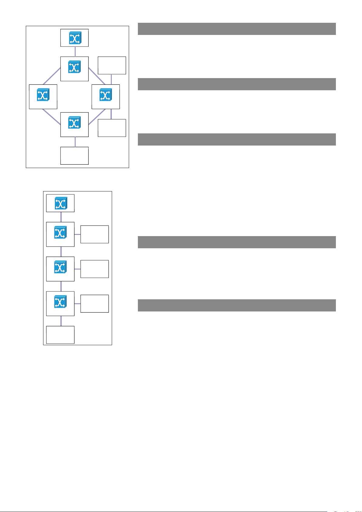
MPH200
MPH100/400
RSTP – rapid spanning tree protocol
Spanning Tree can take 30...60 seconds for each host to decide
whether its ports are actively forwarding trafc. Rapid Spanning Tree
(RSTP) detects uses of network topologies to enable faster convergence, without creating forwarding loops.
Port mirroring
MPH200 MPH200
Other
network
MPH200
MPH100/400
device
Redundant ring with MPH200 encoders.
MPH100/400
MPH200
MPH100/400
MPH200
Port mirroring monitors and mirrors network trafc by forwarding copies
of incoming and outgoing packets from a monitored port to a monitoring
port. Users specify which target port receives copies of all trafc passing
through a specied source port.
Link aggregation (trunking)
MPH200 Ethernet Switch supports ingress and egress port aggregation
in accordance with IEEE Std 802.3ad. Any number of ports can be
aggregated into any number of groups. Frames are distributed among
the aggregated ports by an advanced frame distribution function, which,
through conguration, can use the following information:
• Source and destination MAC addresses
• Source and destination IP addresses
• TCP/UDP port numbers for IPv4 packets
• Flow label for IPv6 packet
• Pseudo-randomization.
LACP – link aggregation control protocol
LACP uses peer exchanges across links to determine, on an ongoing
basis, the aggregation capability of various links, and continuously
provides the maximum level of aggregation capability achievable
between a given pair of systems. LACP automatically determines,
congures, binds and monitors the port binding within the system.
MPH100/400
MPH200
Other
network
device
Chaining with MPH200 encoders.
802.1X – port-based network access control
The port-based network access standard IEEE Std 802.1X provides a
framework to implement port authentication where only authenticated
ports have access to the network. Ports are initially in an unauthorized
state where normal frame forwarding for the port is disabled. The port
only accepts special authentication frames. Upon authorization, the
network services become enabled for the port, and normal frame
forwarding is possible. The authentication is initiated by extensible
authentication protocol over LAN (EAPOL) frames, which are identied
by the unique bridge group address 01-80-C2-00-00-03.
58 MPH200 series video encoders WebUI user manual
Page 61
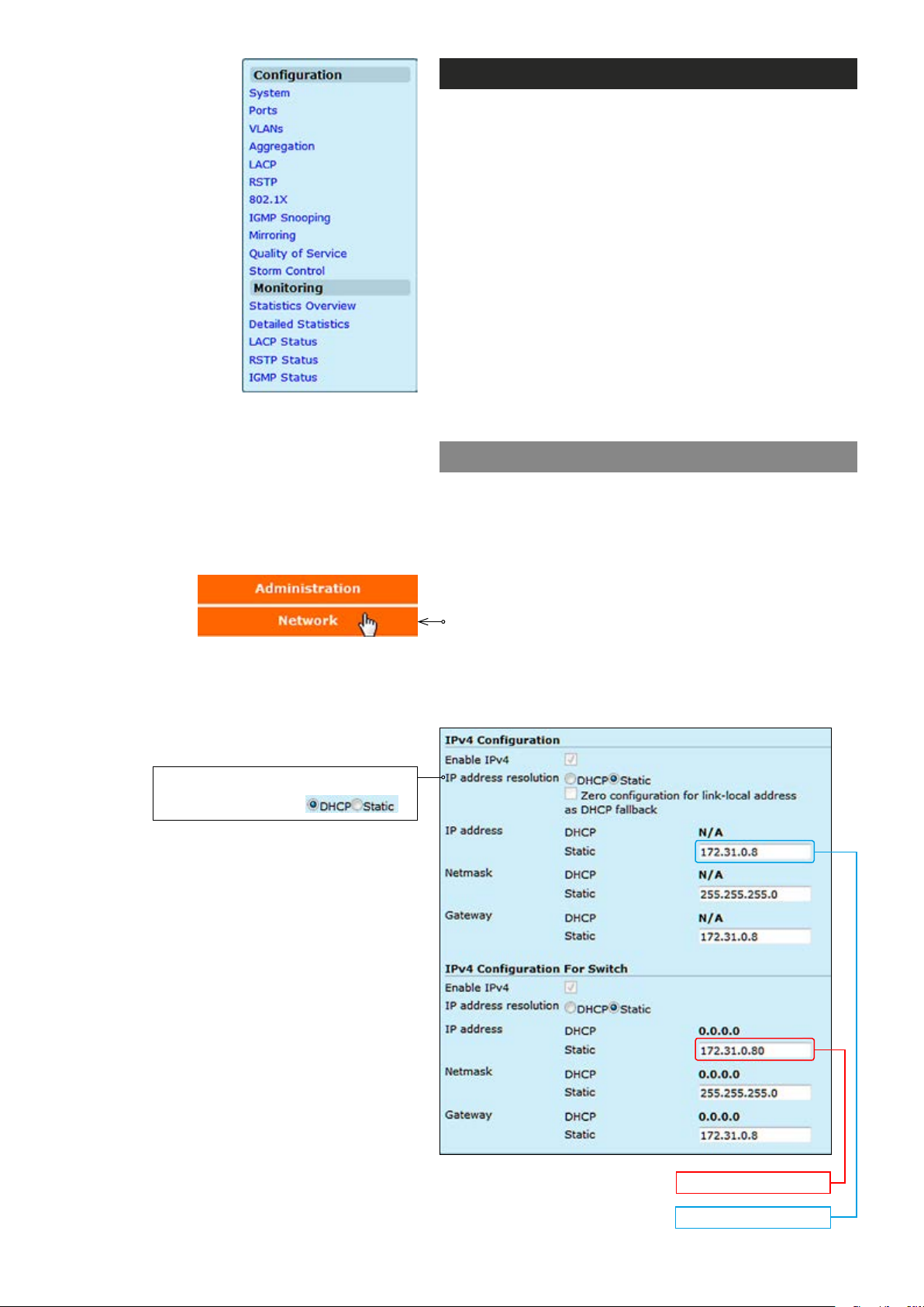
Web user interface
You can manage the switch via Web User Interface (WebUI).
Following options are available:
Conguration
• Set port speed
• Congure simple port-based VLAN
• Enable/disable ow control
• Storm Control Conguration
• Congure RSTP parameters
• Congure QoS
• Congure and monitor IGMP snooping
Monitoring
• Read and clear port statistics
• Monitor LACP status
• Monitor RSTP status
• Monitor IGMP status
How to access the Ethernet Switch
In order to access the Ethernet switch you need to assign
an IP address to the switch from encoder WebUI. By
default both encoder and ethernet switch IP addresses are
assigned automatically from DHCP server. The IP address
should be in the same IP range as encoder is set.
The default setting is DHCP enabled.
To assign the static IP address, click “Network” under the
Administration menu. NETWORK SETTINGS page
appears on the screen. In the “IPv4 Conguration For
Switch” session you can set the IP address, netmask and
gateway address.
Switch IP address
Encoder IP address
59 MPH200 series video encoders WebUI user manual
Page 62
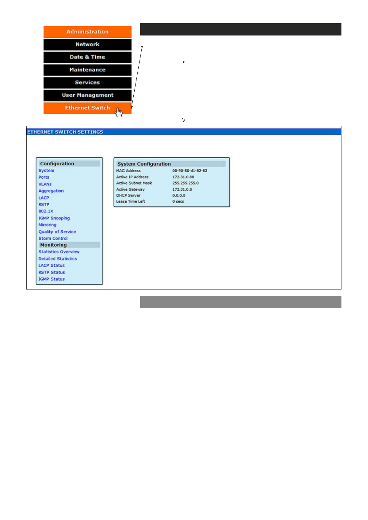
Ethernet switch settings
Click “Ethernet Switch” under the Administration menu.
ETHERNET SWITCH SETTINGS / System Conguration page appears
on the screen.
Mac address:
Active IP Address:
Active Subnet Mask:
Active Gateway:
DHCP Server:
Lease Time Left:
System conguration
Device mac address
Valid IP address
Valid subnet mask
Valid gateway address
Netmask address for subnet denition
The time how long the DHCP server will lease the IP address to the
device using it
60 MPH200 series video encoders WebUI user manual
Page 63
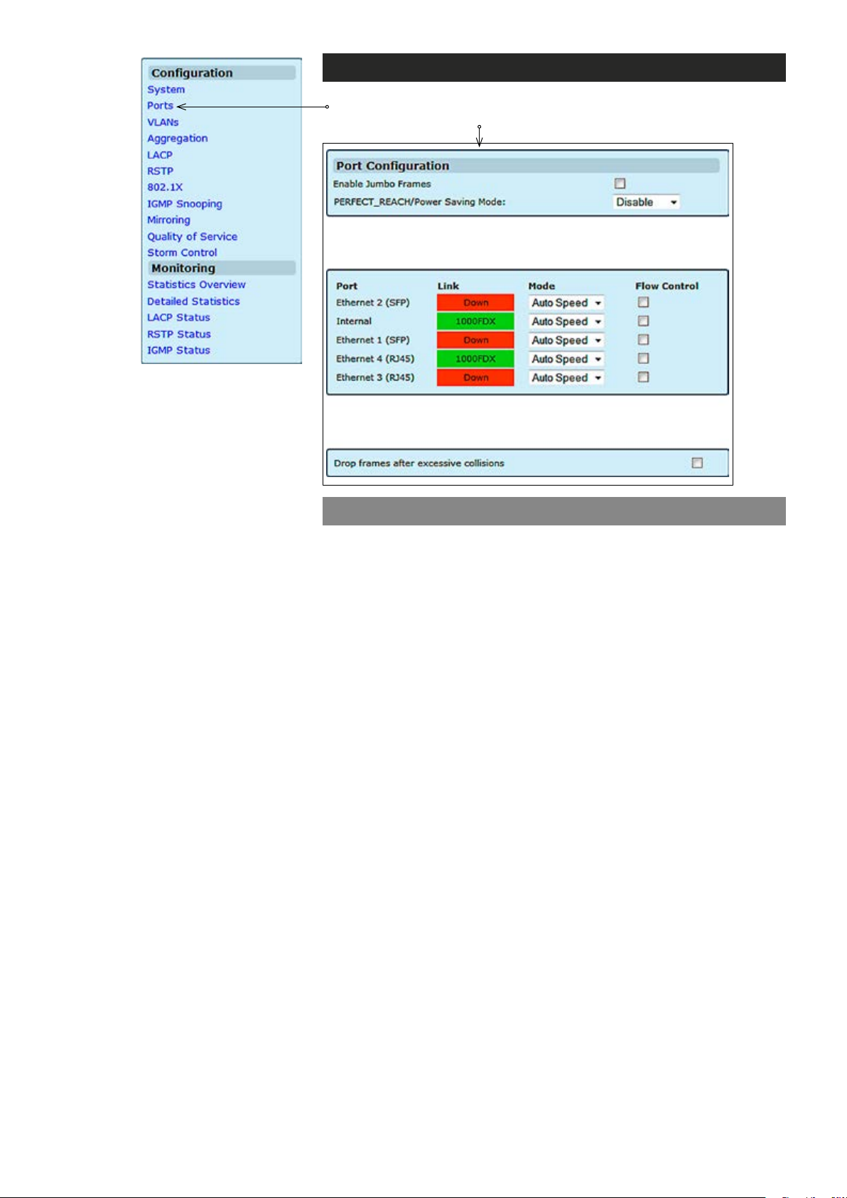
Ports
Click “Ports” under the Conguration menu. Port Conguration page
appears on the screen.
Enable Jumbo Frames:
PERFECT_REACH/Power Saving Mode:
Drop frames after excessive collisions:
Port conguration
Allows you to enable Jumbo (giant) frames which are bigger than the
standard frame size (1518 bytes of payload).
PerfectReach is an intelligent algorithm, it detects the presence of a
shorter cable and then adaptively lowers the power level, saving energy
for links shorter than the full 100 meters of cable length specied by
IEEE standards.
Allows the switch to drop the frame if it has exceeded the maximum of
16 retransmissions in the collision mechanism.
61 MPH200 series video encoders WebUI user manual
Page 64

Virtual LANs (VLANs) – introduction
VLANs are logical partitions of the physical LAN. VLANs are collections of
switching ports that comprise a single broadcast domain. Packets are
classied as belonging to a VLAN based on either the VLAN tag or based
on a combination of the ingress port and packet contents. Packets sharing
common attributes can be grouped in the same VLAN.
You can use VLANs to:
• Increase network performance
• Increase internal network security
• Create separate broadcast domains
If the network has adequate performance and security for your current
needs, it is recommended that you leave the VLAN settings in the default
conguration. The default conguration is as follows:
• All ports are members of VLAN 1
• The switch management interface is on VLAN 1
• All ports have a Port VLAN ID (PVID) of 1
• All ports can send and receive both VLAN-tagged and untagged
packets (i.e. they are “hybrid” ports)
In the default conguration, any port is able to send trafc to any other
port and a PC connected to any port will be able to reach the
management interface. Broadcast trafc, for example, will be ooded to all
ports on the switch.
(this cannot be changed)
VLAN page lets you to congure VLANs per port. The switch can be
congured as either VLAN unaware, behaving transparently toward
VLAN- tagged frames, or as VLAN aware, where VLAN information is
used in the forwarding decision. The switch can maintain 16 VLANs.
For a VLAN-aware (enabled) switch, untagged frames are classied to a
port specic, congurable VLAN identier (PVID). Frames that already
have a VLAN tag when they are received, they will be classied to the VID
within the tag header in the frame.
VLAN-awareness (tagging or untagging frames) can be congured on a
per-port basis. Each port can be congured to a set of ports to which it
can forward and thereby facilitate port-based VLANs. By defaults, all ports
can forward to all other ports
.
Packet type
PCs should be connected to ports with Packet Type set to All. PCs cannot,
in general, send or receive tagged packets. Switches should be connected
to each other with Packet Type set to Tagged.
If the Packet Type is set to All, the port can accept incoming tagged and
untagged packets. Untagged packets will be associated with the VLAN
identied by the PVID. Tagged packets will be dropped unless the port is a
member of the VLAN identied by the VLAN tag in the packet. Outgoing
packets will be tagged unless the packet’s VLAN ID is the same as the PVID.
If the Packet Type is set to Tagged, the port will drop untagged packets and
will only send and receive tagged packets. Tagged packets will be dropped
unless the port is a member of the VLAN identied by the VLAN tag in the
packet. The PVID has no effect in this case.
62 MPH200 series video encoders WebUI user manual
Page 65

Ingress VLAN classication
The switch always classies incoming frames to a VLAN. In the VLANunaware mode, this classication does not inuence the forwarding of the
frame, whereas in the VLAN-aware mode, then classication is used to
make forwarding decisions. If VLAN tags are available in a frame, the
VLAN classication is always based on the outer tag in the frame.
Egress VLAN handling
The switch egress port decides which frames to transmit tagged and which
frames to transmit untagged. The following shows how the tagging or
untagging is performed at the egress port:
Do not tag frames: This applies when switch is running as VLAN-unaware
mode or when the port is VLAN-aware but congured as an access port.
Tag all frames: This applies when the port is congured as a trunk port.
Tag all frames except those with a specic VID: This applies when the
port congured as hybrid port, frames with a specic VID won’t be tagged.
VLAN IDs
VLAN ID number can be any number from 2 to 3290, or from 3293 to 4094.
(VLAN ID 1 is reserved for the default VLAN, which is used for untagged
frames received on the interface. VLAN IDs 3291...3292 are reserved and
cannot be used.) To create a VLAN, enter the ID number and click Add VLAN.
• VLAN 1 is a special VLAN; it cannot be deleted and, if there is a
possibility that a port could become isolated, the Web User Interface
will add the port to VLAN 1.
• You can add up to 16 VLANs to the conguration of the switch. Each
VLAN must be given a VLAN ID in the range 1...4094.
• A port can be a member of up to 16 VLANs.
• All packets travelling through the switch are associated with one and
only one VLAN.
• If a port is not a member of a VLAN, it cannot send or receive packets
associated with that VLAN.
• A tagged packet carries its VLAN ID in the payload of the packet.
• An untagged packet, received on a port with Packet Type set to All, is
associated with the VLAN identied by the PVID.
Port VLAN ID – PVID
PVID is the VLAN ID that is associated with untagged, ingress packets.
It is not possible to remove a port from VLAN 1 unless its PVID has been
changed to something other than 1.
Outgoing packets are tagged unless the packet’s VLAN ID is the same as
the PVID. When the PVID is set to “None,” all outgoing pacekts are tagged
(trunk port).
63 MPH200 series video encoders WebUI user manual
Page 66
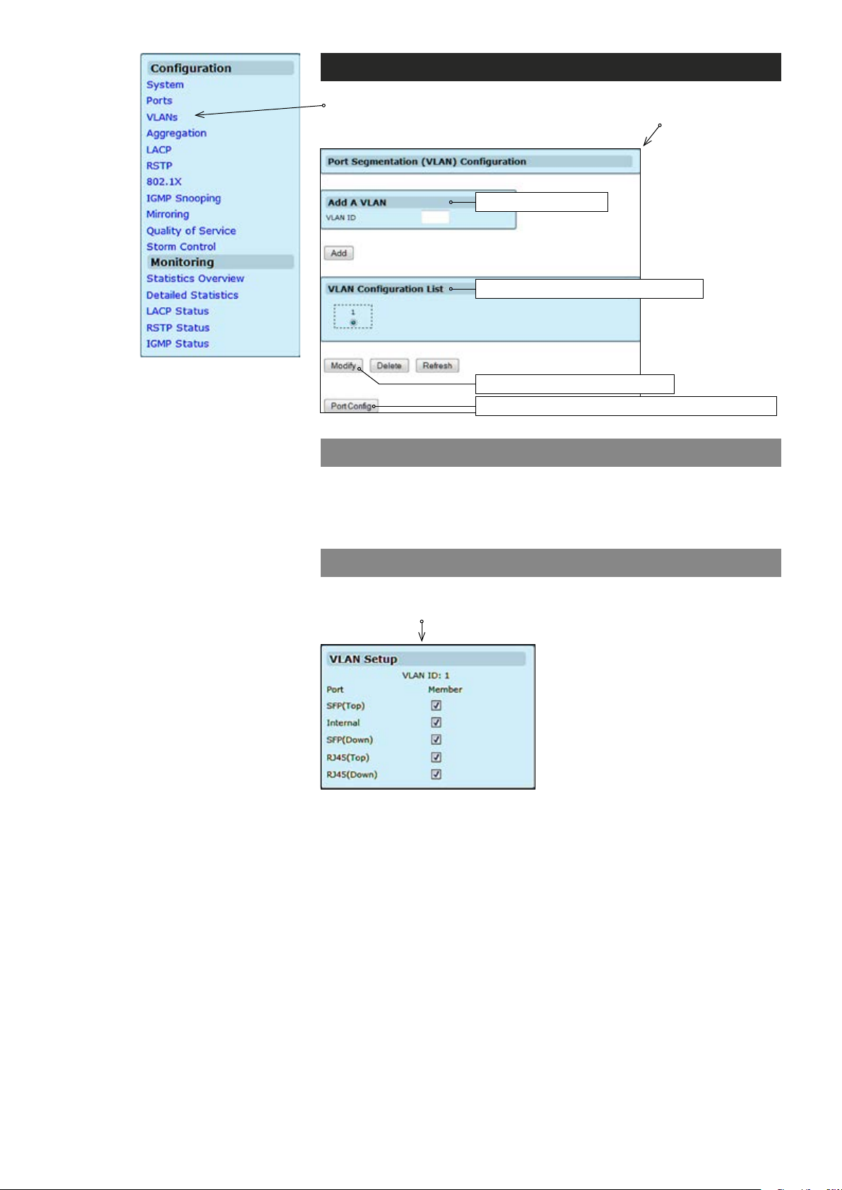
VLANs conguration
Click “VLANs” under the Conguration menu. Port Segmentation
(VLAN) Conguration page appears on the screen.
Adds a new VLAN
Shows the list of available VLANs
Opens VLAN Setup subpage
Opens VLAN Per Port Conguration subpage
Port segmentation (VLAN) conguration
VLAN ID:
VLAN Conguration List:
Port:
Member:
Sets VLAN ID (identication of the VLAN).
Adds the VLAN specied in the VLAN ID eld to the VLAN Conguration list.
VLAN setup
Click “Modify” button on the VLANs page. VLAN Setup page appears
on the screen.
Shows available ports.
Adds the VLAN specied in the VLAN ID eld to the VLAN Conguration list.
64 MPH200 series video encoders WebUI user manual
Page 67
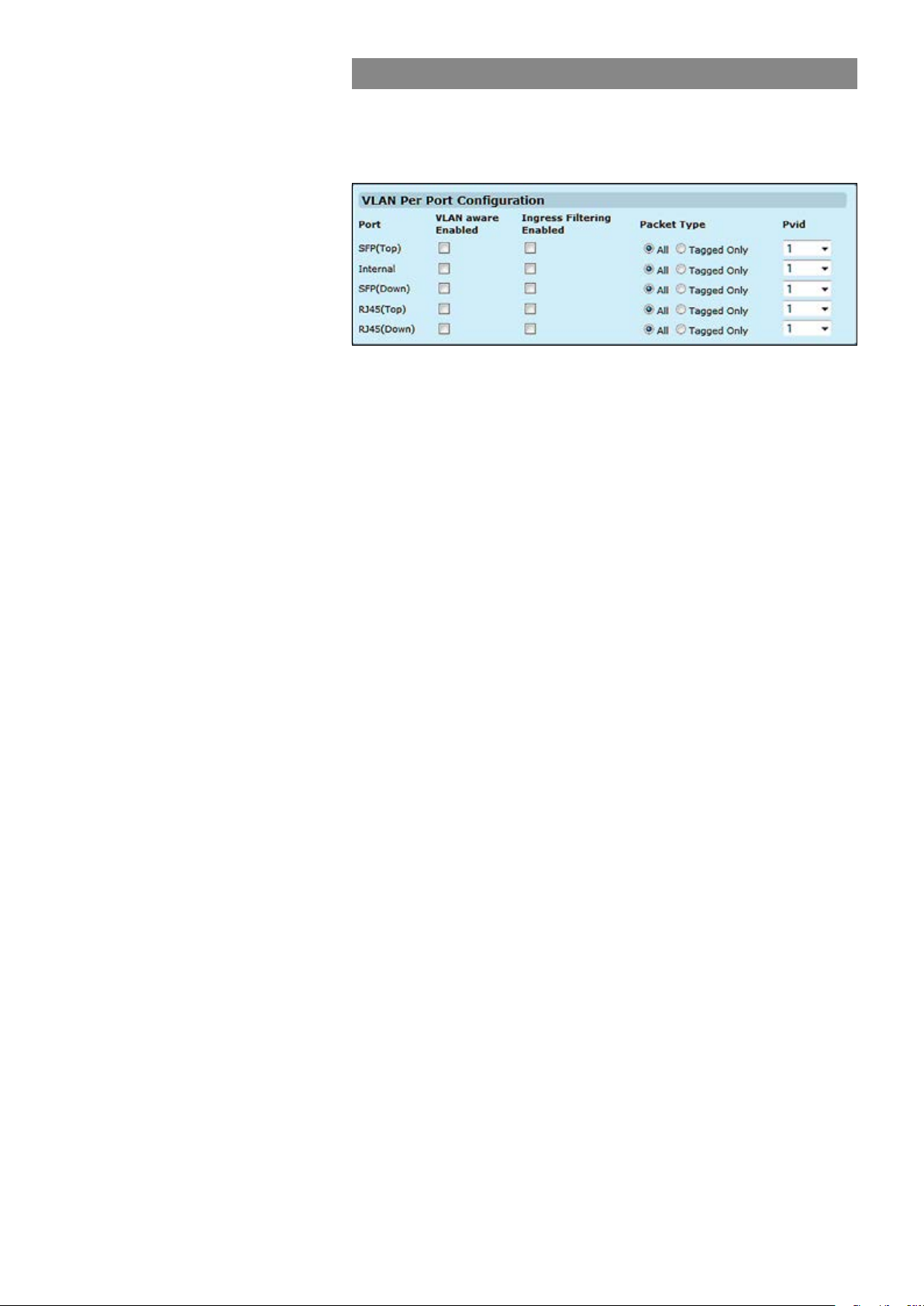
VLAN per port conguration
Click “Port Cong” button on the VLANs page. VLAN Per Port
Conguration page appears on the screen. This page allows you to
congure the VLAN parameters for individual ports.
VLAN aware Enabled:
Ingress Filtering Enabled:
Packet Type:
Pvid:
VLAN aware ports are able to use VLAN tagged frames to determine
the destination of the frame. Click to enable or disable VLAN awareness
mode for this port. (Default: Disabled).
If enabled, incoming frames for VLANs which do not include this ingress
port as a member will be discarded. (Default: Disabled).
Set a port’s handling of tagged and untagged packets. (Default: All).
Set the Port VLAN ID. (Default: 1).
65 MPH200 series video encoders WebUI user manual
Page 68
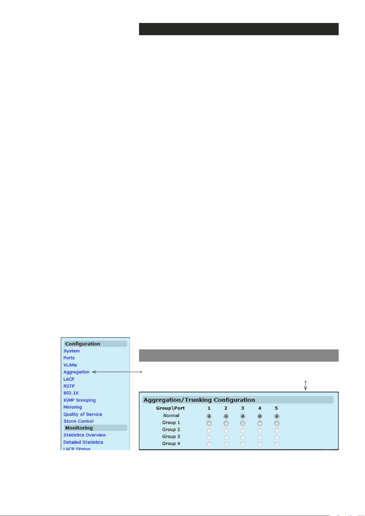
Aggregation – introduction
Link aggregation (trunking) allows any number of ports to be grouped
together automatically using Link Aggregation Control Protocol (LACP),
or manually, to form an ultra-high-bandwidth connection to the network
backbone, which helps prevent trafc bottlenecks. MPH200 Ethernet
Switch supports LACP.
Link aggregation (IEEE Std 802.3ad) describes a way of aggregating
multiple links together to form what appears to be a single link. The
goals are to increase bandwidth and to reduce the risk of link failures.
Link aggregation groups can be dened statically.
The system provides up to four link aggregated groups. Aggregated
links may be dened, each with up to four member ports, to form a
single link aggregated group. Link aggregated groups provide:
• Fault tolerance protection from physical link disruption
• Higher bandwidth connections
• Improved bandwidth granularity
• High bandwidth server connectivity
• Link aggregated group is composed of ports with the same speed,
set to full-duplex operation.
The software will automatically detect that a link has gone down and
then reassign packet distribution on the other links in the group.
MPH200 Ethernet Switch supports ingress and egress port aggregation
in accordance with IEEE Std 802.3ad. Any number of ports can be
aggregated into any number of groups. Frames are distributed among
the aggregated ports by an advanced frame distribution function, which,
through conguration, can use the following information:
• Source and destination MAC addresses
• Source and destination IP addresses
• TCP/UDP port numbers for IPv4 packets
• Flow label for IPv6 packet
• Pseudo-randomization
Note! If port mirroring is enabled and mirrors frames to a port in
an aggregation group, all mirrored frames go to the mirror port
without reecting the other ports in the aggregation group.
Aggregation conguration
Click “Aggregation” menu under the conguration heading. Aggrega-
tion/Trunking Conguration page appears on the screen.
Group \ Port:
Normal / Group1-4:
66 MPH200 series video encoders WebUI user manual
Ethernet port number.
Click the tick-box of the port you would like to add to the link aggregation groups (LAGs).
Page 69
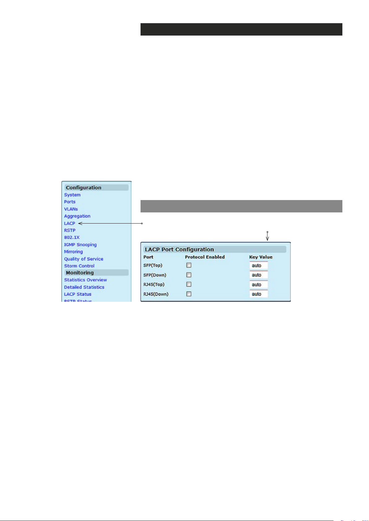
LACP – introduction
Link Aggregation Control Protocol (LACP) is part of the IEEE
specication 802.3ad. LACP congured ports can automatically
negotiate a trunked link with LACP-congured ports on another device.
You can congure any number of ports on the switch as LACP, as long
as they are not already congured as part of a static trunk. If ports on
another device are also congured as LACP, the switch and the other
device will negotiate a trunk link between them.
A Gigabit Ethernet port channel balances the trafc load across the links
by reducing part of the binary pattern formed from the addresses in the
frame to a numerical value that selects one of the links in the channel.
Bundled ports equally inherit the logical MAC addresses on the port
channel interface.
LACP supports the automatic creation of Gigabit Ethernet port channels
by exchanging LACP packets between ports. It learns the capabilities of
port groups dynamically and informs the other ports. Once LACP
identies correctly matched Ethernet links, it facilitates grouping the
links into a Gigabit Ethernet port channel.
LACP conguration
Protocol Enabled:
Key Value:
Click “LACP” menu under the conguration heading. LACP Port
Conguration page appears on the screen.
Allows LACP to be enabled or disabled. When the box is checked, Key
Value (0..255, 0 means auto-generated key). Used to determine the link
aggregation group membership, and to identify this device to other
switches during negotiations.
67 MPH200 series video encoders WebUI user manual
Page 70
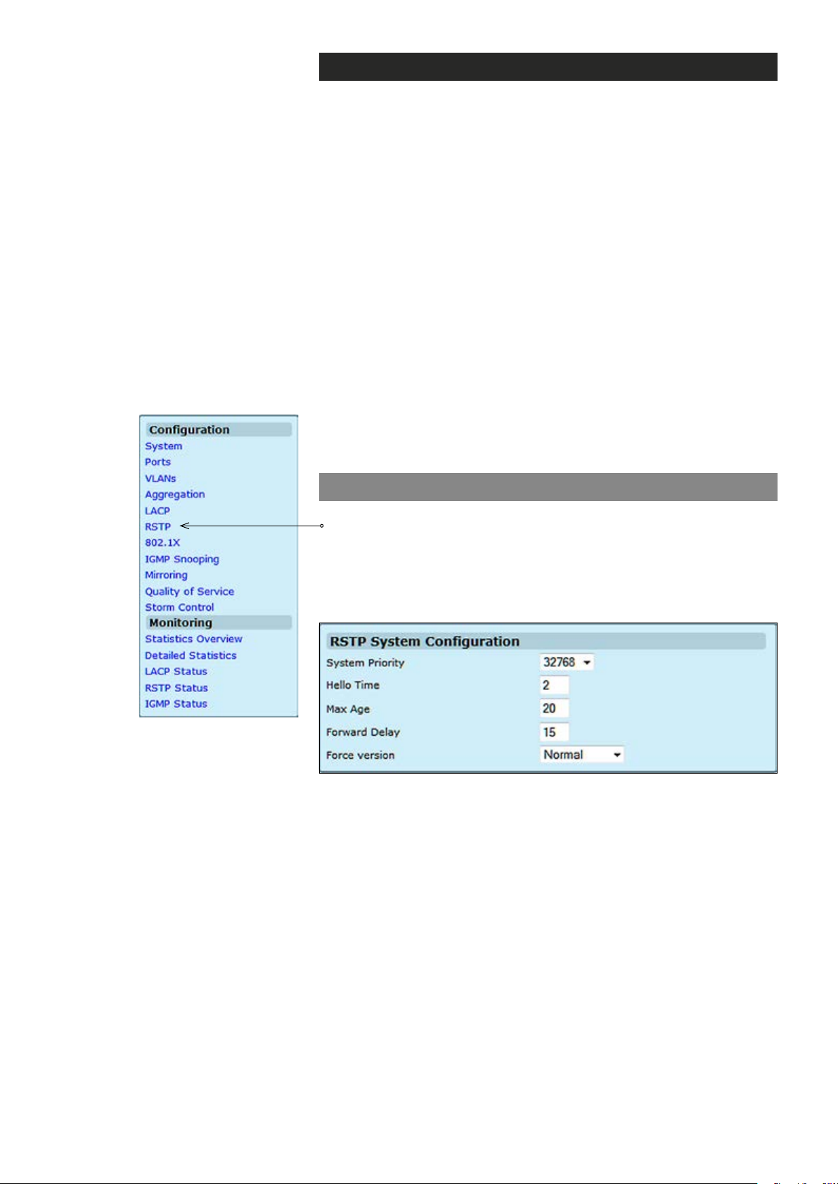
Spanning tree (STP/RSTP) – introduction
The Spanning Tree Algorithm (STA) can be used to detect and avoid
network loops, and to provide backup links between switches, bridges or
routers. This allows the switch to interact with other bridging devices
(that is, an STA-compliant switch, bridge or router) in your network to
ensure that only one route exists between any two stations on the
network, and provide backup links which automatically take over when a
primary link goes down.
The spanning tree algorithms supported by this switch include
these versions:
• STP – Spanning Tree Protocol (IEEE 802.1D).
STP is a standard Layer 2 switch requirement that allows bridges to
automatically prevent and resolve L2 forwarding loops. Switches
exchange conguration messages using specically formatted frames
and selectively enable and disable forwarding on ports.
• RSTP – Rapid Spanning Tree Protocol (IEEE 802.1w).
RTP can take 30-60 seconds for each host to decide whether its ports
are actively forwarding trafc. Rapid Spanning Tree (RSTP) detects
network topologies to achive faster convergence, without creating
forwarding loops.
System Priority:
Hello Time:
Max Age:
Forward Delay:
Force version:
RSTP conguration
Click “RSTP” under the Conguration menu. RSTP System
Conguration page appears on the screen. The page is composed of
two tables:
• RSTP System Conguration - Congure global system settings.
• RSTP Port Conguration - Setup port related settings.
This parameter congures the spanning tree priority globally for this
switch. The device with the highest priority becomes the STA root device.
However, if all devices have the same priority, the device with the lowest
MAC address will then become the root device. Number between
0...61440 in increments of 4096. Therefore, there are 16 distinct values.
Interval (in seconds) at which the root device transmits a conguration
message (BPDU frame). Number between 1...10 (default is 2).
The maximum time (in seconds) a device can wait without receiving a
conguration message before attempting to recongure. That also
means the maximum life time for a BPDU frame. Number between
6...40 (default is 20).
The maximum time (in seconds) the root device will wait before changing
states (i.e., discarding to learning to forwarding). Number between 4...30
(default is 15).
Set and show the RSTP protocol to use.
Normal = use RSTP,
Compatible = compatible with STP.
68 MPH200 series video encoders WebUI user manual
Page 71
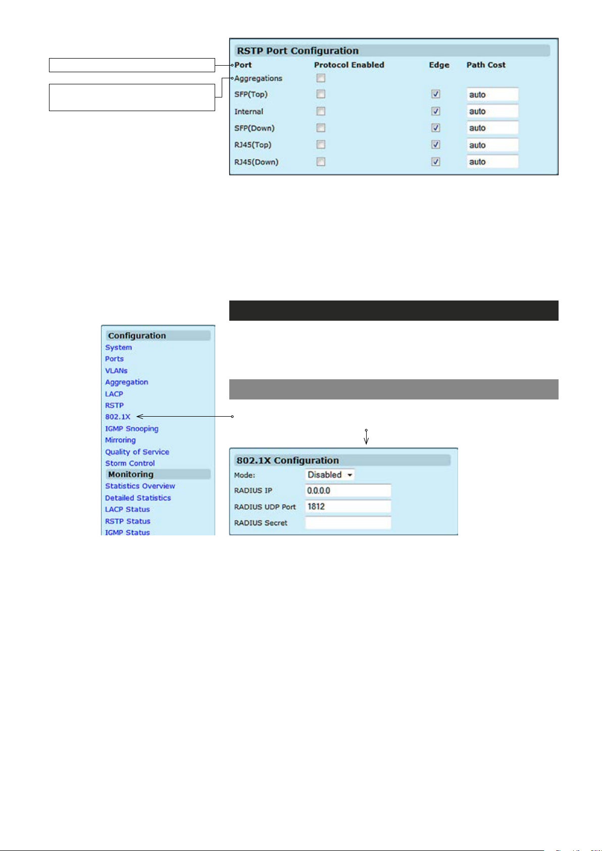
The port ID. It cannot be changed.
Aggregations means any
congured trunk group
Protocol Enabled:
Edge:
Path Cost:
Click on the tick-box to enable/disable the RSTP protocol for the port.
Expect the port to be an edge port (linking to an end station) or a link to
another STP device.
This parameter is used by the STP to determine the best path between
devices. Therefore, lower values should be assigned to ports attached
to faster media, and higher values assigned to ports with slower media.
Set the RSTP pathcost on the port. Number between 0...200000000.
802.1X – introduction
The 802.1X (IEEE 802.1X) standard denes a port-based access
control procedure that prevents unauthorized access to a network by
requiring users to rst submit credentials for authentication.
802.1X conguration
Click “802.1X” under the Conguration menu. 802.1X Conguration
page appears on the screen.
Mode:
RADIUS IP:
RADIUS UDP Port:
RADIUS Secret:
69 MPH200 series video encoders WebUI user manual
Indicates if 802.1X protocol is globally enabled or disabled on the switch.
Sets the RADIUS server IP address.
Sets the UDP port to the use for the external RADIUS server.
Sets the text string used for encryption between the switch and the
RADIUS server.
Page 72
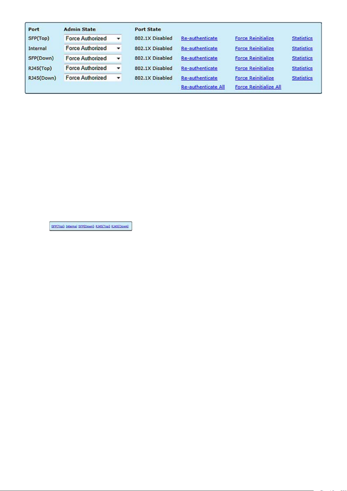
Port:
Admin State:
Port State:
The port number.
Sets the authentication mode to one of the following options:
Auto: Requires a 802.1X-aware client to be authorized by the authentication server. Clients that are not 802.1X-aware will be denied access.
Force-Authorized: Forces the port to grant access to all clients, either
802.1X-aware or otherwise.
Force-Unauthorized: Forces the port to deny access to all clients,
either 802.1X-aware or otherwise.
The state of the port.
Re-Authenticate: Schedules a reauthentication to whenever the
quiet-period of the port runs out.
Force-Reinitialize: Bypasses the quiet-period of the port and enables
immediate reauthentication regardless of the status for the quiet-period.
Statistics
Select the port that you want to view:
Displays 802.1X statistics. Statistics can be viewed on a per-port basis.
:
Authenticator counters: General statistics for authenticator.
Backend Authenticator counters: General statistics for RADIUS server.
802.1X MIB counters: MIB module dened for 802.1X.
70 MPH200 series video encoders WebUI user manual
Page 73
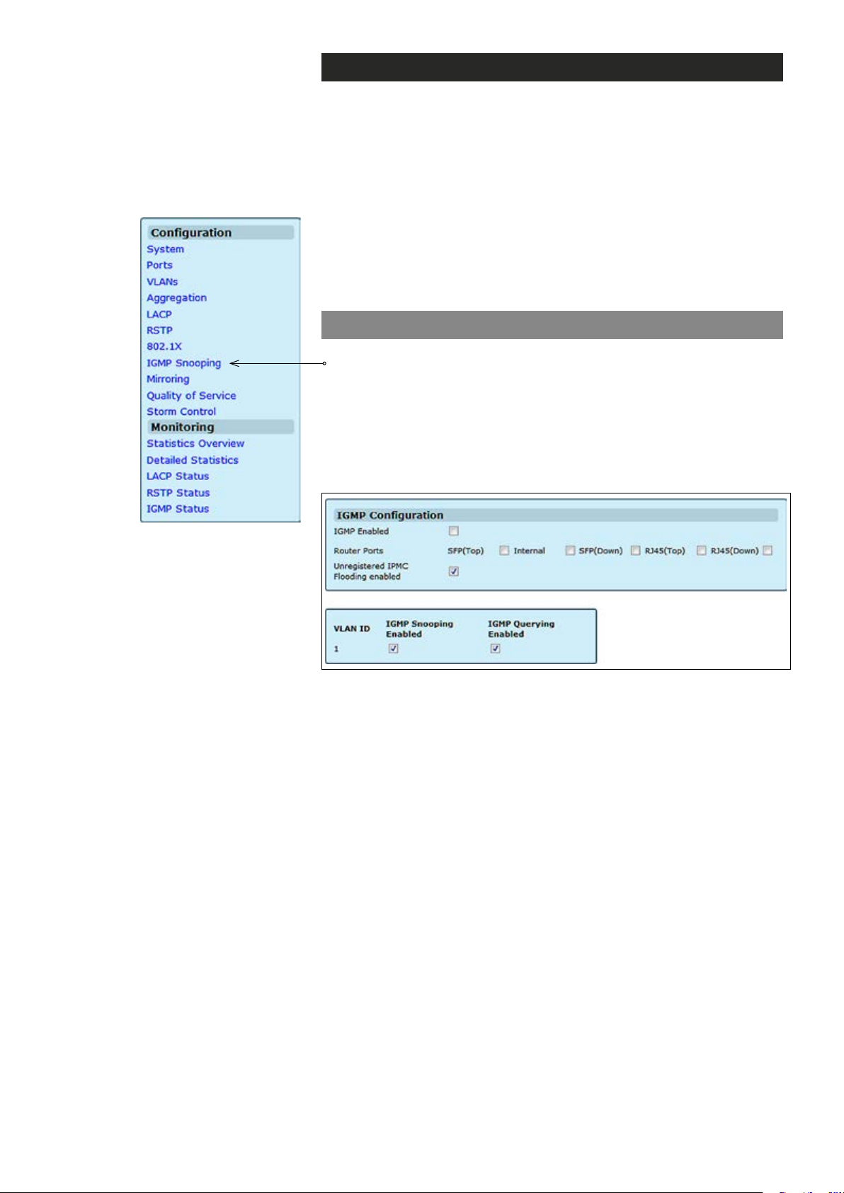
IGMP – introduction
The Internet Group Management Protocol (IGMP) lets host and routers
share information about multicast group memberships. IGMP snooping
monitors IGMP service requests passing between multicast clients and
servers, and dynamically congures the ports which need to receive the
mulitcast trafc.
MPH200 Ethernet Switch provides enhanced support for IP Multicast by
allowing up to 8192 programmable multicast groups to co-exist in the MAC
table. This, in combination with IGMP snooping where IPMC membership
information is passed on to the CPU, enables applications such as digital
video distribution. Source specic multicast (SSM) is not supported.
IGMP conguration
Click “IGMP Snooping” under the Conguration menu. IGMP
Conguration page appears on the screen. This page enables
customers to setup the conguration of IGMP. The page is composed of
two tables:
• IGMP Snooping Conguration – Congure global system settings
• IGMP Snooping VLAN Conguration – Congure VLAN
related settings
IGMP Enabled:
Router Ports:
Unregistered IPMC Flooding enabled:
VLAN ID:
IGMP Snooping Enabled:
IGMP Querying Enabled:
Enables/disables IGMP support on the switch. When enabled, the
switch will monitor network trafc to determine which hosts want to
receive multicast trafc.
Enable Router Port if it is leading towards the IGMP querier (switch or router
having IGMP querying function enabled).
Enabling this will make the switch ood the unregistered (not joined)
multicast to all ports and disabling will make the switch forward unregistered
multicast trafc to the router ports only.
The VLAN ID. It can not be changed.
Enables/disables IGMP snooping on a VLAN. When enabled, the port will
monitor network trafc to determine which hosts want to receive the multicast trafc.
Enables/disables IGMP querier on the VLAN. When enabled, the port can
serve as the Querier, which is responsible for asking hosts if they want to
receive multicast trafc.
71 MPH200 series video encoders WebUI user manual
Page 74
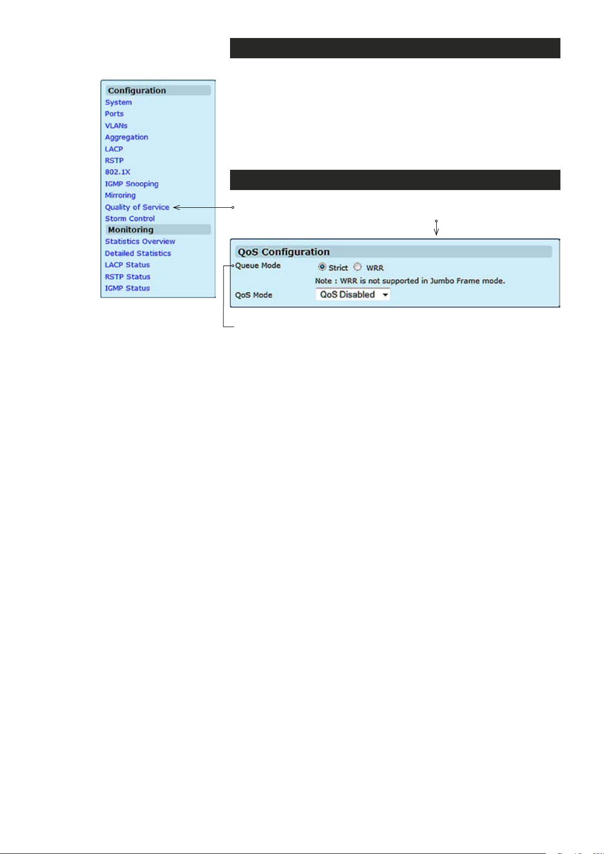
Quality of service (QoS) – introduction
QoS conguration enables the switch to use resources more efciently
to ensure high-quality performance for critical applications. QoS is a
mechanism which is used to prioritize certain trafc as it is moves
through the switch. Trafc can be classied as High, Medium, Normal or
Low priority. This switch features both strict priority-based and weighted
round-robin (WRR) forwarding, with guaranteed bandwidth allocation for
the different QOS classes.
QoS conguration
Click “Quality of Service” under the Conguration menu. QoS
Conguration page appears on the screen.
Queue Mode
QoS Mode
The Queue Mode can be selected by ticking the radio button:
:
Strict
: Higher priority frames take precedence over lower priority frames
during forwarding. In case of congestion, the lowest priority trafc is dropped
before higher priority frames. Head-of-queue blocking maybe encountered
by using this mode.
WRR
: In this mode, all priorities can be guaranteed a share of the bandwidth when the system is overloaded. The bandwidth sharing percentage
can be adjusted by specifying the four QOS class with different ratio in WRR
Weight, which appears after WRR is enabled in Queue Mode
Note! WRR is selectable only when Jumbo Frame is disabled in
Ports / Settings.
:
The QoS Mode can be selected using the QoS Mode drop-down list:
QoS Disabled: QoS is turned off and all packets have equal priority.
802.1p: Packets are prioritzed using the content of the VLAN-tag.
DSCP/DiffServ : Packets are prioritized using the DSCP/DiffServ
(Differentiated Services Code Point) value.
Note: Only one QoS mode can be active at one time. It is not
possible, for example, to prioritise trafc using the DSCP/DiffServ
and 802.1p.
.
72 MPH200 series video encoders WebUI user manual
Page 75
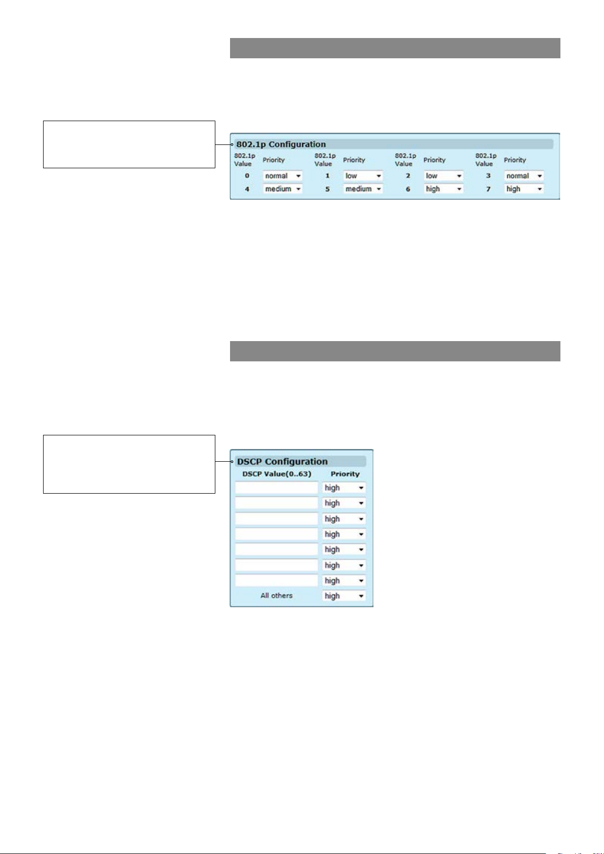
When QoS Mode is set to 802.1p,
the 802.1p Conguration table
appears which allows a priority to
be set for each of the eight values.
802.1p conguration
The 802.1p eld is held within the VLAN-tag of a packet. The eld is
three bits long so can hold eight values; 0...7 inclusive. When QoS
Mode is set to 802.1p, the 802.1p Conguration table appears which
allows a priority to be set for each of the eight values.
You can use the Priority drop-down list to quickly set the values in the
802.1p Conguration table. Select Low to set all values to low priority,
Normal to set all values to normal priority, Medium to set all values to
medium priority, or select High to set all values to high priority. Use
Custom if you want to set each value individually.
Note: Because end-stations, like PCs, are not usually VLAN
aware, they do not create VLAN-tagged frames. As a result, this
method of prioritization is not ideal when there are a lot of PCs
connected to the switch.
When QoS Mode is set to DSCP/
DiffServ, the DSCP Conguration
table appears which allows a
priority to be set for each of the
DSCP/DiffServ values.
DSCP conguration
DSCP (DiffServ/Differentiated Services Code Point) is a six bit eld that
is contained within an IP (TCP or UDP) header. Six bits allows the
DSCP eld to take any value in the range 0...63 inclusive. When QoS
Mode is set to DSCP, the DSCP/DiffServ Conguration table appears
which allows a priority to be set for each of the DSCP values.
You can use the Priority drop-down list to quickly set the values in the
DSCP Conguration table. Select Low to set all values to low priority,
Normal to set all values to normal priority, Medium to set all values to
medium priority, or select High to set all values to high priority. Use
Custom if you want to set each value individually.
73 MPH200 series video encoders WebUI user manual
Page 76
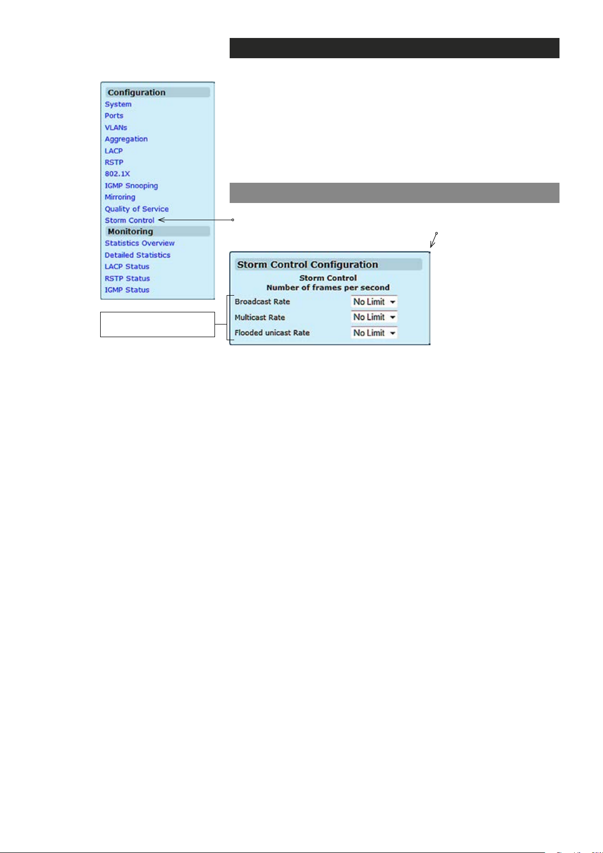
Type of trafc which
can be rate limited
Storm control – introduction
This page allows you to set up a threshold for incoming broadcast and
multicast packets. Too many incoming packets can severely cripple the
switch and network performance. Rate limiting protects the switch and
network by keeping the amount of data passing through the ports to a
safe limit. The use of VLANs and Trunks to partition ports and network
devices into separate groups can also keep the network from
unnecessary trafc by restricting the packet destination. The same
setting is applied to all the ports on the switch.
Storm control conguration
Click “Storm Control” under the Conguration menu. Storm Control
Conguration page appears on the screen.
List the type of trafc which can be rate limited, including Broadcast,
Multicast and Flooded unicast frames.
The Rate eld is set by a single drop-down list. The same threshold is
applied to every port on the switch. When the threshold is exceeded,
packets are dropped, irrespective of the ow-control settings.
74 MPH200 series video encoders WebUI user manual
Page 77

Command line interface - CLI
General
The MPH series video encoder unit includes a command line interface
(CLI) for conguration purposes. The CLI is a screen interface that
allows the user to interact with the operating system by entering commands and optional arguments.
The MPH supports CLI over UART (RS-232), Telnet and SSH.
CLI is accessed through any terminal emulator application. The command structure is the same for all session types.
Note! PuTTY is a free and open source terminal emulator applica-
tion which can act as a client for the SSH, Telnet, rlogin, and raw
TCP computing protocols and as a serial console client. Tera Term
has comparable features to PuTTY. Hyper Terminal is not
included in Windows Vista or later.
The CLI can be accessed in the following ways:
• Serial data connection (RS232), via Data 2 port, with a serial
connection cable.
• TCP/IP connection, via active Ethernet port.
System requirements for CLI
Connection through Data 1 port locally (UART):
* PC equipped with terminal emulator application supporting VT100 /
102 or ANSI protocols, e.g. Hyper Terminal, PuTTY or Tera Term.
* RS232-cable (type Teleste CIC506)
Connection through Ethernet port remotely (Telnet/SSH):
* PC equipped with terminal emulator application supporting Secure
Shell (SSH) network protocol, e.g. PuTTY or Tera Term.
* Ethernet-connection
75 MPH200 series video encoders CLI user manual
Page 78
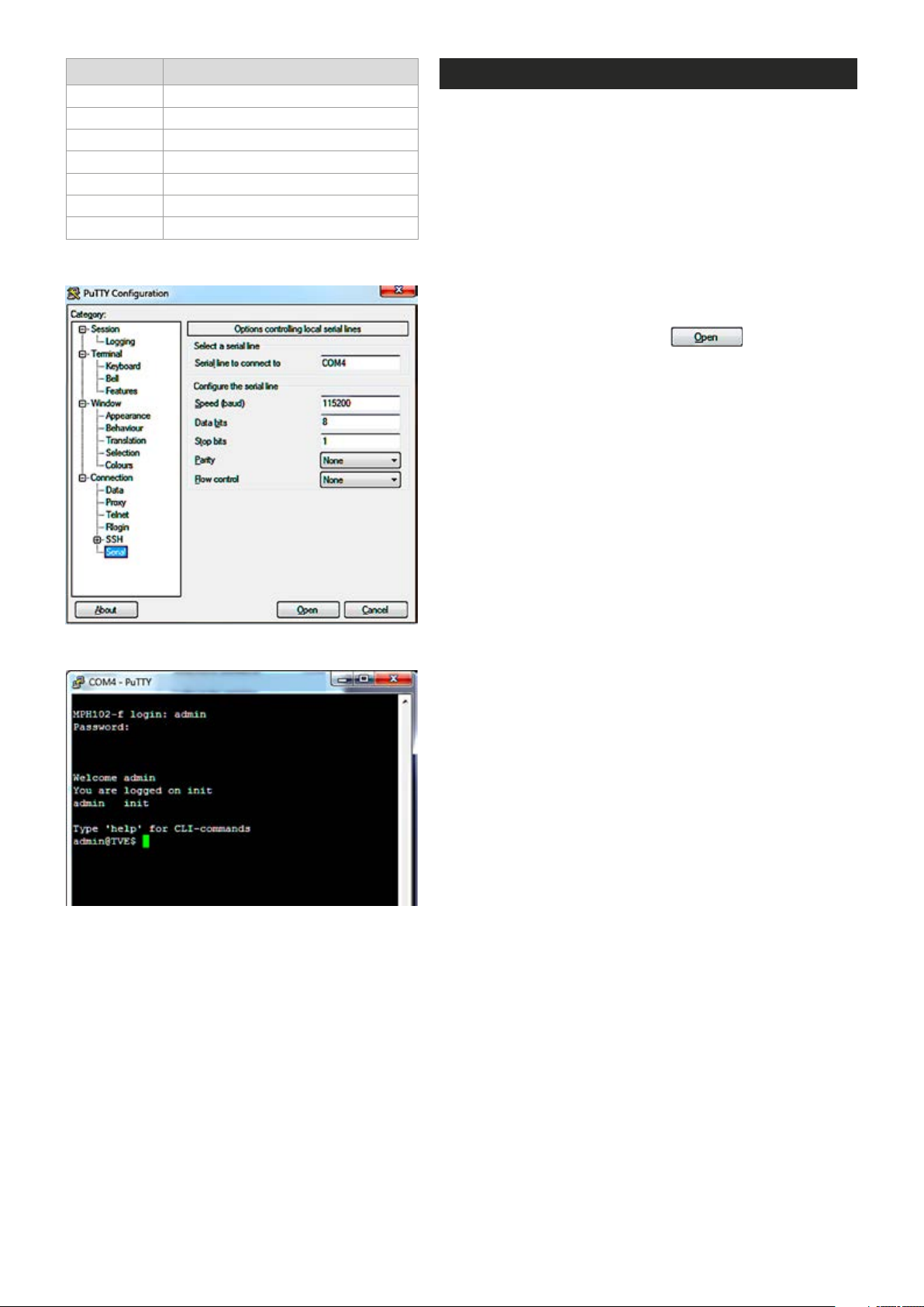
Setting Value
Emulation VT100, VT102 or ANSI
Protocol RS232 (serial)
Baud rate 115 200 kbps
Data bits 8
Parity None
Stop bits 1
Flow control None
Port settings to local serial (RS-232) connection.
Connection methods - local serial connection
This chapter describes how to connect to CLI locally (via
serial cable) using Putty terminal emulator application.
1. Start the Putty terminal emulator application. Wait until
the following “Putty Conguration” window appears on
the screen.
2. Select Serial category to continue. The following “Op-
tions controlling local serial lines” window appears on
the screen.
3.
Choose COM port where the serial (RS232) cable is
connected, e.g. COM4 port and then set here the values as
described in table beside. Click OPEN to continue. The
blank “COM4 - PuTTY” window appears on the screen.
4. To activate the terminal connection rst press Enter -->
“MPH241-f login:” appears on the screen (MPH name
depends on device in question).
5. Enter the required user name and the password (admin/
admin
window appears on the screen. The terminal connection
to MPH series video encoder device is now completed
and you can now use the CLI commands to management
the device.
for administrator)
. The MPH Hyper Terminal
Serial (COM port) settings in Putty.
COM port settings in Putty.
The terminal connection can be terminated by selecting File/
Exit, Alt+F4 or clicking x on the right upper corner of Hyper
Terminal window.
76 MPH200 series video encoders CLI user manual
Page 79
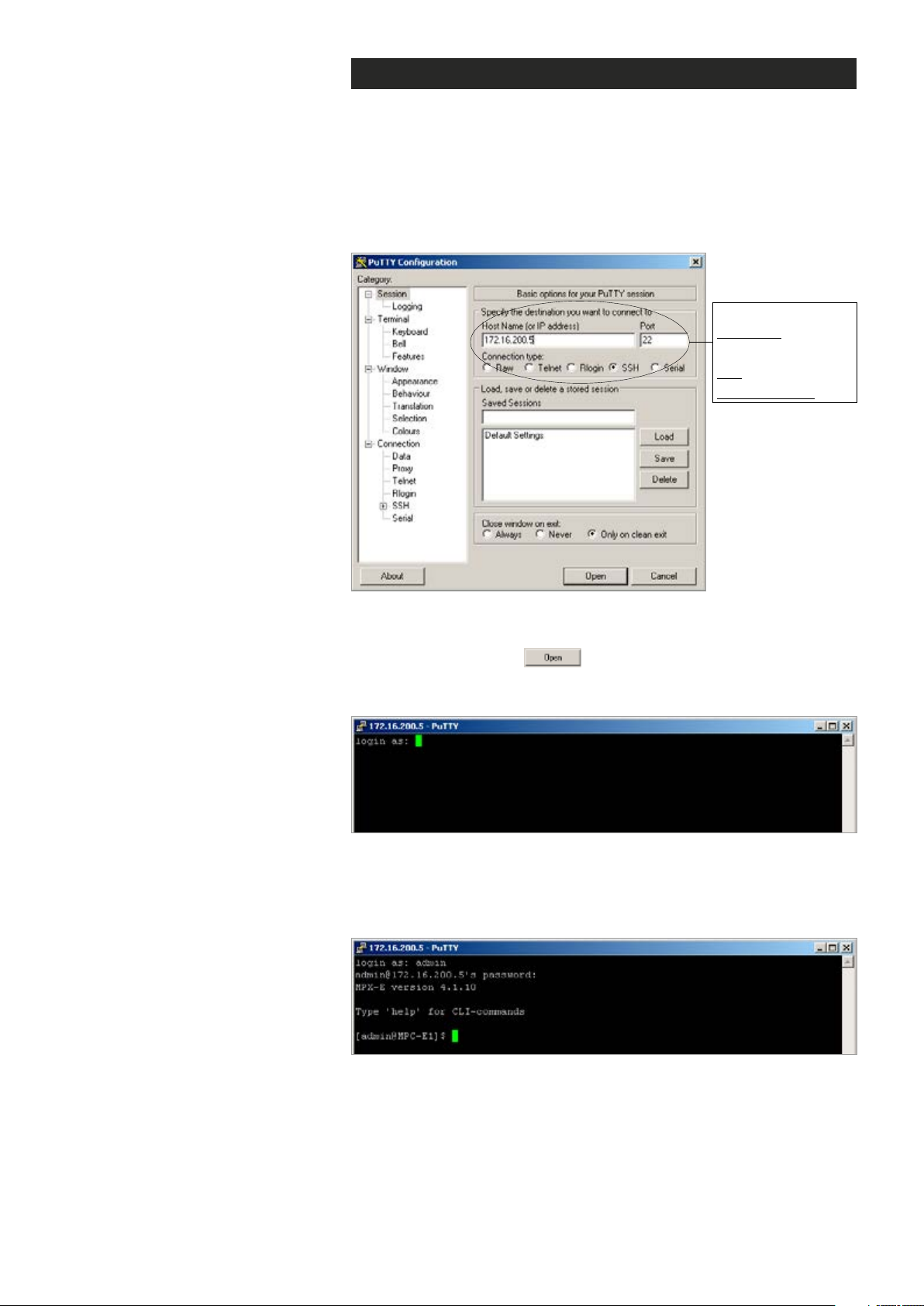
Connection methods - TCP/IP
This chapter describes how to connect to CLI via TCP/IP connection
using Putty terminal emulator application. The same menus that are
displayed on a local terminal are instantly available over an IP network.
1.
Start the PuTTY application. Wait until the following “PuTTY Congura-
tion” window appears on the screen:
Required settings:
IP address:
Device IP address
Port: 22
Connection type: SSH
PuTTY application view (Windows XP).
2.
Enter the device IP address into the “Host Name (or IP address)”
address bar and click to continue.
The following “PuTTY” window appears on the screen:
Telnet program view.
3.
Enter the required user name and the password. The following
“172.16.200.5 - PuTTY” window appears on the screen:
The CLI connection to MPH series video encoder is now completed and
you can now use the CLI commands to management the device.
The CLI connection can be terminated by entering command exit.
77 MPH200 series video encoders CLI user manual
Page 80
Command Description
up Jump to previous level
help
exit Exits the session
Displays a list of available
commands in level
Detailed descriptions of CLI commands
CLI lets you enter several commands. To execute a command, press
enter after typing command. By entering “Help” command you get a list
of all available commands. To get more information about how to use a
specic command you can enter “Help + specic command”.
Ctrl+C is the interrupt key and returns user to the prompt.
Note! letters can be typed either lowercase or uppercase.
Main menu
Enter the help command to view a CLI main menu:
**************************************
Main menu
**************************************
datetime sub menu
devmgmt sub menu
ethswitch sub menu
network sub menu
up
help
exit
-------------------------
Use the setutc command to change
device date and time settings.
Datetime command
Enter the datetime command to view datetime menu:
**************************************
datetime menu
**************************************
setutc
up
help
exit
-------------------------
Entering help setutc displays a list of options for setutc command:
setutc <-src=time_src> [<-date=date_str>] [<-time=time_str>]
Description:
Sets UTC date and time parameters. If no arguments are passed,
the command will display current date and time
<time_src>: manual/ntp
If manual mode is selected, then date and time should be
provided
[<date_str>]: Date in DD/MM/YYYY format
[<time_str>]: Time in HH:MM:SS 24 hour format
78 MPH200 series video encoders CLI user manual
Page 81

Devmgmt command
Enter the devmgmt command to view devmgmt menu:
**************************************
devmgmt menu
**************************************
reboot
softfactoryreset
hardfactoryreset
licenseupdate
swversion
swud
getconf
putconf
up
help
exit
-------------------------
Available CLI commands in devmgmt menu. These commands allows
you to manage device, as make factory resets, update rmware and
save/restore device settings.
Use the reboot command to restart
the device.
Use the softfactoryreset command to
make soft factory reset to the device.
Use the hartfactoryreset command to
make hard factory reset to the device.
Entering help reboot displays information about the reboot command:
reboot
Description:
Reboot the device.
Entering help softfactoryreset displays information about the
softfactoryreset command:
softfactoryreset
Description:
Soft factory resets the device. Specific configurations will
be reset to factory defaults. The device will reboot on this
command
Entering help
hartfactoryreset
hardfactoryreset
Description:
Hard factory resets the device. All configurations will be
reset to factory defaults. The device will reboot on this
command
hartfactoryreset
command:
displays information about the
79 MPH200 series video encoders CLI user manual
Page 82

Entering help licenseupdate displays information about
the licenseupdate command:
Use the licenseupdate command to
activate a new licence to the device.
Use the swversion command to
view the current rmware version of
the device.
Use the swud command to change
device’s rmware.
licenseupdate [<license_key>]
Description:
Update product license key. The license key will be validated
against device serial number before updating. The device
will reboot after successfully updating the license key. If
the licensekey is not provided, this command will print the
current license key
[<license_key>]: Product license key string. If this string is
not provided, current license key will be displayed
Example:
licenseupdate MPH-1A-E1CGAX-AXXAXXOXXXXXXXXX,HL00000000,0,EJPKOJ-XLJAYA-I72CA2
Entering help swversion displays information about
the swversion command:
swversion
Description:
Prints the current software version
Entering help swud displays information about the swud command:
swud <tftp link>
Description:
Downloads software image from tftp and update. Device will
reboot once the software image is downloaded successfully
Use the getconf command to
download stored conguration from
a TFTP - server.
Use the putconf command to
upload the current conguration to
a TFTP - server.
<tftp link>: String of upto 128 characters with tftp://<ip_
address>/software_image format
Example:
swud tftp://192.168.36.148/tvelightimage.bin
Entering help getconf displays information about the getconf command:
getconf <-ip=server_ip> <-file=config_file_name>
Description:
Download configuration file from tftp server and restore
configurations. Device will reboot once the file is downloaded
successfully
Example:
getconf -ip=192.168.36.148 -file=tve.cfg
Entering help putconf displays information about the putconf command:
putconf <-ip=server_ip> <-file=config_file_name>
Description:
Upload configuration file to tftp server for backup. The file
name can be chosen by the user
Example:
putconf -ip=192.168.36.148 -file=tve.cfg
80 MPH200 series video encoders CLI user manual
Page 83

Use the help command to see
information on a command (usage:
enter “help + the specied command”,
for example: help help displays
information from help command.
Ethswitch command
CLI lets you manage device’s internal Ethernet switch. Enter the
ethswitch command to view ethswitch menu:
**************************************
ethswitch menu
**************************************
help
Commands at top level:
System - System commands
Console - Console commands
Port - Port commands
MAC - MAC commands
VLAN - VLAN commands
Aggr - Aggregation commands
LACP - IEEE 802.3ad Link Aggregation commands
RSTP - IEEE 802.1w Rapid Spanning Tree commands
User Group - User Group commands
QoS - QoS commands
Mirror - Mirror commands
IP - IP commands
Dot1x - Dot1x commands
IGMP - IGMP Snooping commands
Debug - Debug commands
>ENDOFCMD
-------------------------
These commands allows you to manage Ethernet Switch settings. To get
more information about how to use a specic CLI command on the menu,
enter help + command, for example: port help displays all commands at
port level.
81 MPH200 series video encoders CLI user manual
Page 84

System command
Enter the system command to go to System level:
Commands at System level:
System Configuration [all]
System Restore Default [keepIP]
System Name [<name>]
System Reboot
System SNMP [enable|disable]
System Trap [<IP Address>]
System Readcommunity [<community string>]
System Writecommunity [<community string>]
System Trapcommunity [<community string>]
System Power Saving [full|up|down|disable]
Console command
Enter the console command to go to Console level:
Commands at Console level:
Console Configuration
Console Password [<password>]
Console Timeout [<timeout>]
Console Prompt [<prompt string>]
Port command
Enter the port command to go to Port level:
Commands at Port level:
Port Configuration [<portlist>]
Port Mode [<portlist>] [<mode>]
Port Flow Control [<portlist>] [enable|disable]
Port State [<portlist>] [enable|disable]
Port MaxFrame [<portlist>] [<framesize>|reset]
MAC command
Enter the mac command to go to MAC level:
Port Statistics [<portlist>] [clear]
Port Excessive Collisions Drop [enable|disable]
Port VeriPHY [<portlist>] [full|anomaly|termination]
82 MPH200 series video encoders CLI user manual
Page 85

MAC command
Enter the mac command to go to MAC level:
Commands at MAC level:
MAC Configuration
MAC Add <macaddress> <portlist>|none [<vid>]
MAC Delete <macaddress> [<vid>]
MAC Lookup <macaddress> [<vid>]
MAC Table <vidlist>
MAC Flush
MAC Agetime [<agetime>]
VLAN command
Enter the vlan command to go to VLAN level:
Commands at VLAN level:
VLAN Configuration [<portlist>]
VLAN Add <vidlist> [<portlist>]
VLAN Delete <vidlist>
VLAN Lookup <vidlist>
VLAN Aware [<portlist>] [enable|disable]
VLAN PVID [<portlist>] [<vid>|none]
VLAN Frame Type [<portlist>] [all|tagged]
VLAN Ingress Filtering [<portlist>] [enable|disable]
Aggr command
Enter the aggr command to go to Aggr level:
Commands at Aggr level:
Aggr Configuration
Aggr Add <portlist>
Aggr Delete <portlist>
Aggr Lookup <portlist>
Aggr Mode [smac|dmac|xor]
83 MPH200 series video encoders CLI user manual
Page 86

LACP command
Enter the lacp command to go to system level:
Commands at LACP level:
LACP Configuration [<portlist>]
LACP Mode [<portlist>] [enable|disable]
LACP Key [<portlist>] [<key>|auto]
LACP Status
LACP Statistics
RSTP command
Enter the rstp command to go to console level:
Commands at RSTP level:
RSTP Configuration [<portlist>]
RSTP sysprio [<sysprio>]
RSTP hellotime [<secs>]
RSTP maxage [<hops>]
RSTP fwddelay [<secs>]
RSTP version [normal|compat]
RSTP Mode [<portlist>] [enable|disable]
RSTP Aggr [enable|disable]
RSTP Edge [<portlist>] [enable|disable]
RSTP Pathcost [<portlist>] [<pathcost>|auto]
RSTP mcheck <portlist>
RSTP Status
RSTP Statistics
User Group command
Enter the user group command to go to system level:
Commands at User Group level:
User Group Configuration
User Group Add <grouplist> [<portlist>]
User Group Delete <grouplist>
User Group Lookup <grouplist>
84 MPH200 series video encoders CLI user manual
Page 87

QoS command
Enter the qos command to go to console level:
Commands at QoS level:
QoS Configuration [<portlist>]
QoS Mode [<portlist>] [tag|port|diffserv]
QoS Default [<portlist>] [<class>]
QoS Tagprio [<portlist>] [<tagpriolist>] [<class>]
QoS DiffServ [<dscpno>] [<class>]
QoS Userprio [<portlist>] [<tagprio>]
QoS Storm Control [<traffic type>] [enable|disable] [<rate>]
<class> range: low|normal|medium|high
<traffic type>: Broadcast|Multicast|Flood Unicast
Mirror command
Enter the mirror command to go to system level:
Commands at Mirror level:
Mirror Configuration
Mirror Port [<port>]
Mirror Source [<portlist>] [enable|disable]
IP command
Enter the ip command to go to console level:
Commands at IP level:
IP Configuration
IP Status
IP Setup [<ipaddress> [<ipmask> [<ipgateway>]]] [<vid>]
IP Mode [enable|disable]
IP Ping [-n <count>] [-w <timeout>] <ipaddress>
IP Arp
IP Dhcp [enable|disable]
IP tftp [enable|disable]
IP tftpget server-ip filename
IP tftpput config|image|backup server-ip filename
85 MPH200 series video encoders CLI user manual
Page 88

Dot1x command
Enter the dot1x command to go to system level:
Commands at Dot1x level:
Dot1x Configuration
Dot1x Mode [enable|disable]
Dot1x State [<portlist>] [Auto|ForceAuthorized|ForceUnauthorized]
Dot1x Server [<IP Address>]
Dot1x UDP Port [<value>]
Dot1x Secret [<Shared Secret>]
Dot1x Statistics [<portlist>]
Dot1x Reauthenticate [<portlist>] [now]
Dot1x Parameters [<parameter>] [<value>]
IGMP command
Enter the igmp command to go to console level:
Commands at IGMP level:
IGMP Configuration
IGMP Status
IGMP Groups <vidlist>
IGMP Mode [enable|disable]
IGMP State <vidlist> [enable|disable]
IGMP Querier <vidlist> [enable|disable]
IGMP Router ports [<portlist>] [enable|disable]
IGMP Unregistered Flood [enable|disable]
Debug command
Enter the debug command to go to system level:
Commands at Debug level:
Debug Read Register <block> <subblock> <address>
Debug Write Register <block> <subblock> <address> <value>
Debug PHY Read <portlist> [<address>] [<page>]
Debug PHY Write <portlist> <address> <value> [<page>]
Debug Loopback [int|ext]
86 MPH200 series video encoders CLI user manual
Page 89

Network command
Enter the network command to view network menu:
**************************************
network menu
**************************************
linkstatus
linklevel
ip
hostname
dns
ntp
up
help
exit
-------------------------
Use CLI commands in network menu to congure device IP settings.
Use the linkstatus command to see
information from the network interface and link status.
Use the linklevel command to set link
mode and mtu size.
Use the ip command to change
device IP settings.
Entering help linkstatus displays information about the linkstatus command:
linkstatus
Description:
Displays network interface and link status
Entering help linklevel displays information about the linklevel command:
linklevel [<-mode=mode_str>] [<-mtusize=mtu_size>]
Description:
Sets the link mode and/or mtu size.
mode_str: Can be one of the following:
auto : Auto negotiation
100FD : 100 mbps full duplex
100HD : 100 mbps half duplex
mtu_size: MTU size in bytes (Valid range: 64 to 1500)
If no arguments are passed, the command will display current
configuration
Entering help
ip <-mode=ip_mode> [<-addr=ip_addr>] [<-mask=subnet>]
[<-gate=gateway>]
ip
displays information about the ip command:
Description:
Sets the IP mode. Also sets IP address, subnet and gateway in
case of static IP mode only
If no arguments are passed, the command will display the
current configuration.
<ip_mode>: static / dhcp
An example how to change device
IP address, subnet and gateway:
network
ip -mode=static -addr=172.31.252.13
If manual mode is selected, then ip address, subnet mask and
gate way also should be provided
[<ip_addr>]: IP address
[<subnet>]: Subnet mask
-mask=255.255.0.0 -gate=172.31.2.1
[<gateway>]: Default gateway
Caution: If ip address is changed, you might have to login
using new IP address. Change in IP address might make the
device in-accessbile from your network if configured to a
different subnet
87 MPH200 series video encoders CLI user manual
Page 90

Entering help hostname displays information about
the hostname command:
Use the hostname command to set
a hostname to the device.
Use the dns command to set DNS
parameters to the device.
hostname [<hostname_string>]
Description:
Sets the hostname. If no arguments are passed, the command
will display current configuration
[<hostname_string>]: Hostname upto 32 characters (without
special characters or spaces)
Entering help dns displays information about the dns command:
dns <-mode=dns_mode>[<-domain=search_domains>][<-servers=dns_
servers>]
Description:
Sets DNS parameters. If no arguments are passed, the command
will display current configuration
<dns_mode>: manual/dhcp
If manual mode is selected, search domains and dns servers
should be provided
dhcp mode is available only if ‘ip mode’ is set to DHCP.
Otherwise only manual mode is available.
[<search_domains>]: Comma seperated list of search domains
in decreasing order of priority (Upto 3 search domains are
Entering help swud displays information about the swud command:
supported)
Use the swud command to change
device’s rmware.
[<dns_servers>]: Comma seperated list of dns servers in
decreasing order of priority (Upto 3 search dns servers are
supported)
Entering help ntp displays information about the ntp command:
ntp <-mode=ntp_mode> [<-servers=ntp_servers>]
Description:
Sets NTP parameters. If no arguments are passed, the command
will display current configuration
<ntp_mode>: manual/dhcp
If manual mode is selected, ntp server list should be provided
dhcp mode is available only if ‘ip mode’ is set to DHCP.
Otherwise only manual mode is available.
[<ntp_servers>]: Comma seperated list of ntp servers in
decreasing order of priority (Upto 3 search ntp servers are
supported)
88 MPH200 series video encoders CLI user manual
Page 91
MPH200 specications
130
292.13
Video MPH241 MPH242
CVBS video input 1 2
HD-SDI video input 1* Encoding channels up to 4
Total streams up to 8
Coding H.264/MJPEG/MPEG-4/MPEG-2*
Resolution QCIF/CIF/2CIF/4CIF,
Frame rate (fps) 1...25 PAL, 1...30 NTSC
Max. Performance (25/30 fps)
H.264, MJPEG,
MPEG-4*, MPEG-2*
or 1 x 720p + 1 x 4CIF/D1*
ONVIF Yes
SNMP* Yes
Motion detection Yes
Camera tampering Yes
Text overlay Yes
SAP Yes (Session Announcement Protocol)
NTP Yes (Network Time Protocol)
RTSP Yes (Real Time Streaming Protocol)
Data channels 2
Standard Data 1: RS422/485, Data 2: RS232
Audio channels 2
Coding G.711. G.726, AAC-LC, AAC-HE*
Contact closures 2 in, 1 out
Ethernet ports 4
VLAN 16 ids
Multicast IGMP v1, v2
Link redundancy STP/RSTP
Protocols RTP, UDP, TCP, IP, HTTP, DHCP, SSH, Telnet, DHCP, DNS, ZeroConf, ICMP, ARP, QoS
SFP support* Yes
Management
Size (H x W x D) 52.5 x 130 x 254
Operating temperature -34...+74 °C (-29...+165 °F)
Power consumption 13 W
Power Over Ethernet PoE+, 802.11at, 15W (class 4)
* = option
WebUI / SNMP / CLI (password protected user groups with different user levels, CLI via serial or SSH connection)
or 1 HD*
or 1 HD*
½D1/D1/720p*/1080i*
4 x 4CIF/D1
or 1 x 720p/1080p*
Gigabit Ethernet (electrical or optical)
up to 4
up to 6
QCIF/CIF/2CIF/4CIF,
½D1/D1
2 x 4CIF/D1
(per video input)
267.25
89 MPH200 series video encoders user manual
Page 92

Legal declarations
Copyright © 2014 Teleste Corporation. All rights reserved.
TELESTE is a registered trademark of Teleste Corporation. Other product and
service marks are property of their respective owners.
This document is protected by copyright laws. Unauthorized distribution or
reproduction of this document is strictly prohibited.
Teleste reserves the right to make changes to any of the products described in
this document without notice and all specications are subject to change without
notice. Current product specications are stated in the latest versions of detailed
product specications.
To the maximum extent permitted by applicable law, under no circumstances shall
Teleste be responsible for any loss of data or income or any special, incidental,
consequential or indirect damages howsoever caused.
The contents of this document are provided “as is”. Except as required by applicable
law, no warranties of any kind, either express or implied, including, but not limited
to, the implied warranties of merchantability and tness for a particular purpose, are
made in relation to the accuracy, reliability or contents of this document.
Teleste reserves the right to revise this document or withdraw it at any time
without notice.
Teleste Corporation
P.O. Box 323
FI-20101 Turku
Street address: Telestenkatu 1, 20660 Littoinen
FINLAND
www.teleste.com
 Loading...