

Page 1
EASI™ IP Series
User Manual
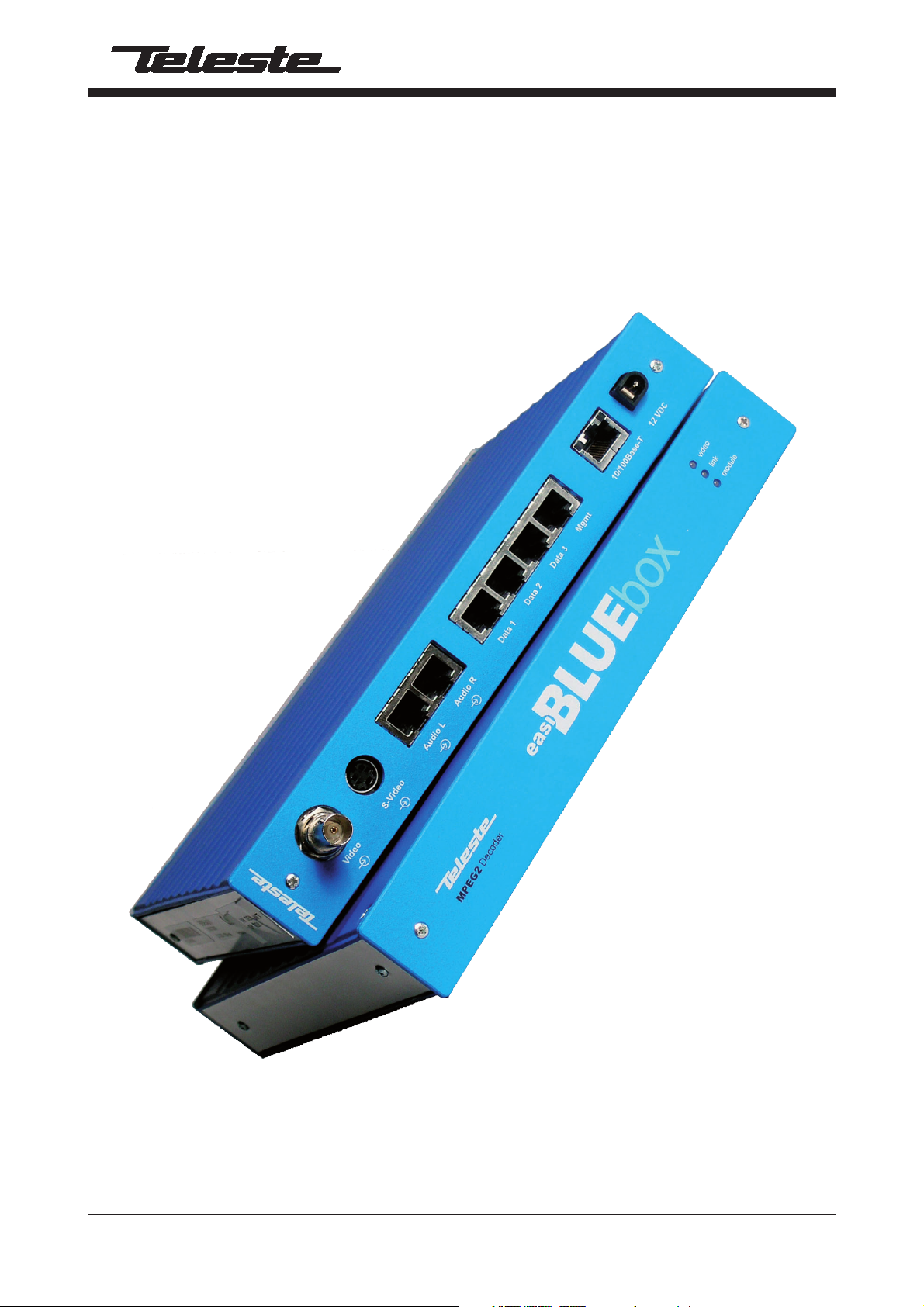
BLUEbox MPEG-2 encoder & decoder
BLUEbox user manual, 59300233, rev002
Page 2

Contents
Introduction ..................................................................................................................................................................... 1
General .................................................................................................................................................................... 1
Software version ...................................................................................................................................................... 1
Features ................................................................................................................................................................... 1
Installation ....................................................................................................................................................................... 2
Quick instructions .................................................................................................................................................... 2
Mechanical connections .......................................................................................................................................... 3
Indicator leds ........................................................................................................................................................... 3
Connections .................................................................................................................................................................... 4
General .................................................................................................................................................................... 4
Video connection ..................................................................................................................................................... 4
Audio connections ................................................................................................................................................... 4
Data connections ..................................................................................................................................................... 5
Mgmt connection ..................................................................................................................................................... 6
Ethernet connection ................................................................................................................................................. 7
TM
Changing the settings of EASI
General .................................................................................................................................................................... 8
Web user interface (WebUI) .................................................................................................................................... 8
Command line interface (CLI) ................................................................................................................................. 8
User groups ............................................................................................................................................................. 8
Web user interface (WebUI) ........................................................................................................................................... 9
Introduci on ............................................................................................................................................................... 9
General .................................................................................................................................................................... 9
Operation ................................................................................................................................................................. 9
Starting ...................................................................................................................................................................10
User groups for WebUI ...........................................................................................................................................10
General information - page .....................................................................................................................................11
Network confi guration - page ..................................................................................................................................12
Video confi guration - page ......................................................................................................................................13
Video management - page .....................................................................................................................................14
SAP management - page ........................................................................................................................................15
Video statistics - page ............................................................................................................................................16
Change password / User management - page .......................................................................................................17
Services - page .......................................................................................................................................................18
Data channel 1...3 - pages ......................................................................................................................................19
Data channel statistics - page ............................................................................................................................... 20
Command Line Interface - CLI..................................................................................................................................... 21
Connection methods - Hyper Terminal .................................................................................................................. 21
Connection methods - Telnet ................................................................................................................................. 22
How to use the CLI ........................................................................................................................................................ 23
CLI levels ............................................................................................................................................................... 23
Detailed descriptions of commands .......................................................................................................................... 24
Disable level ........................................................................................................................................................... 24
Enable level............................................................................................................................................................ 25
Confi g level ............................................................................................................................................................ 26
Confi g-if level for data channels ............................................................................................................................ 27
Confi g-if level for Fast Ethernet ............................................................................................................................. 28
Confi g-sap level ..................................................................................................................................................... 29
Confi g-ts level ........................................................................................................................................................ 30
Confi g-fi lter level .................................................................................................................................................... 31
Confi g-line level ..................................................................................................................................................... 32
Glossary....................................................................................................................................................................33-38
Copyright acknowledgements .................................................................................................................................... 39
Technical specifi cations .............................................................................................................................................. 40
BLUEbox devices ................................................................................................... 8
BLUEbox series user manual rev002
Page 3

BLUEbox encoder & decoder introduction
Stand-alone CAT5 devices with one video, two audio
and three data channels, In-band management
Welcome, and thank you for purchasing Teleste’s
V
x
1
D
x3
A
x2
E
x1
M
EASI™ Products.
gmt
General
EASI™ BLUEbox is a stand-alone video, audio & data
Encoder/Decoder device for business television
type applications.
The permitted supply voltage range is 10.5...18 V DC.
The power consumption is 6 W. The permitted operational
temperature range is -10...+55 °C.
These devices provides not only a transparent link of
PAL or NTSC video signal, but also two uni-directional
audio channels and three independent separately
confi gurable general-purpose asynchronous data
channels in both directions.
BLUEbox MPEG-2 Encoder (BBE) makes up pair with
BLUEbox MPEG-2 Decoder (BBD).
The transmission is accomplished over 10/100Base-Tx
network utilizing TCP/UDP/IP streaming.
These devices are equipped with an MPEG-2 video
compression engine compliant with the ISO/IEC 13818-2
standard. Audio is compressed in the same direction with
video, as described in ISO / IEC 11172-3 MPEG-1 audio
compression standard.
General-purpose asynchronous data channels are
transferred separately from encoded video and audio signals.
Software version
Device functional and operational suitability described in this
manual is for software version BBE 2.4.1 and BBD 2.4.23.
Features
• Selectable CVBS and Y/C video input and output
• Frame rate 25 (PAL), 30 (NTSC)
• Video bit rate scalable up to 3000...10000 kbps
• GOP structure selectable
• Balanced audio input and output
• Bi-directional data interface (EIA232/422/485), user
data rate up to 115kbps / Channel
• Web User Interface / Command Line Interface
• Low latency mode
BLUEbox series user manual rev002 1
Page 4

Installation
Quick Instructions
Install the stand-alone BLUEbox device to the installation place.
1
A 12 V supply voltage is provided by a CPS22x mains adapter.
Switch on the system power and see that the “module”, “link”
and “video” -indicators on the front panel of the device are lit.
2
The “module” should lit green to show that hardware is
operating properly.
Connect all needed audio/data signals to their respective
3
connectors on the device’s rear panel.
Connect either a CVBS video signal to the BNC connector or a
4
S-VIDEO signal to the mini-DIN connector of the device.
Connect the Ethernet 100Base network to port “10/100Base-Tx”
in the rear panel.
5
Note! You can create a local WebUI connection by this
connector using an Ethernet cable (e.g. OPUS1CCC0050X
cross-connection cable).
Create management connection to the device either by over an
Ethernet network or by a Mgmt port and then set all necessary
settings in the device.
Default network addresses for the devices are are the following:
6
BBE: 10.9.96.10 (IP address)
BBD: 10.9.96.20 (IP address)
BBE/BBD: 255.255.255.0 (Netmask address)
Make sure that the device is not indicating any alarms or
warnings. The “module”, “link” and “video” -indicators on the
7
front panel should now lit green. If the “module” indicator is red,
the device in question has a module error and is giving an alarm.
2 BLUEbox series user manual rev002
Page 5
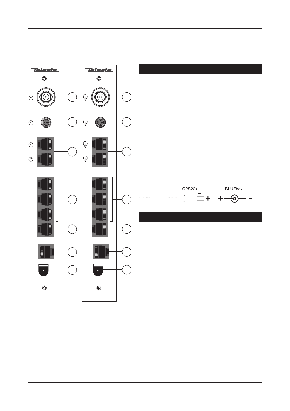
Video S-Video Audio L Audio R Data 1 Data 2 Data 3 Mgmt 10/100Base-T 12 VDC
BLUEbox Mechanical Connections
1. Composite (CVBS) video input / output (BBE / BBD),
BNC female connector.
Video S-Video Audio L Audio R Data 1 Data 2 Data 3 Mgmt 10/100Base-T 12 VDC
1
2
3
2. S-video (Y/C) input / output (BBE / BBD), 4 pin
1
min-DIN female connector.
3. 2 audio inputs / outputs (BBE / BBD), RJ-45
female connector.
2
4. 3 EIA-RS data interfaces, RJ-45 female connector.
5. Management interface for device’s local
3
management operation, RJ-45 female connector.
6. Ethernet 10/100Base interface (CAT-5), RJ-45
female connector.
7. Supply voltage connector (+ 12 VDC)
Picture 1.
BBE Mpeg-2
Encoder / connections.
4
5
6
7
Picture 2.
BBD Mpeg-2
Decoder / connections.
4
Indicator Leds
There is three dual colour leds on the front panel;
5
video-led indicates state of video, link-led indicates
state of Ethernet connection and module-led indicates
state of hardware.
6
The “video”, “link” and “module” -indicators on the front
panel should lit green in normal operation. If the led
indicator is red or yellow, the function in question has a
7
error and is giving an alarm.
BLUEbox series user manual rev002 3
Page 6
Connections
General
43
12
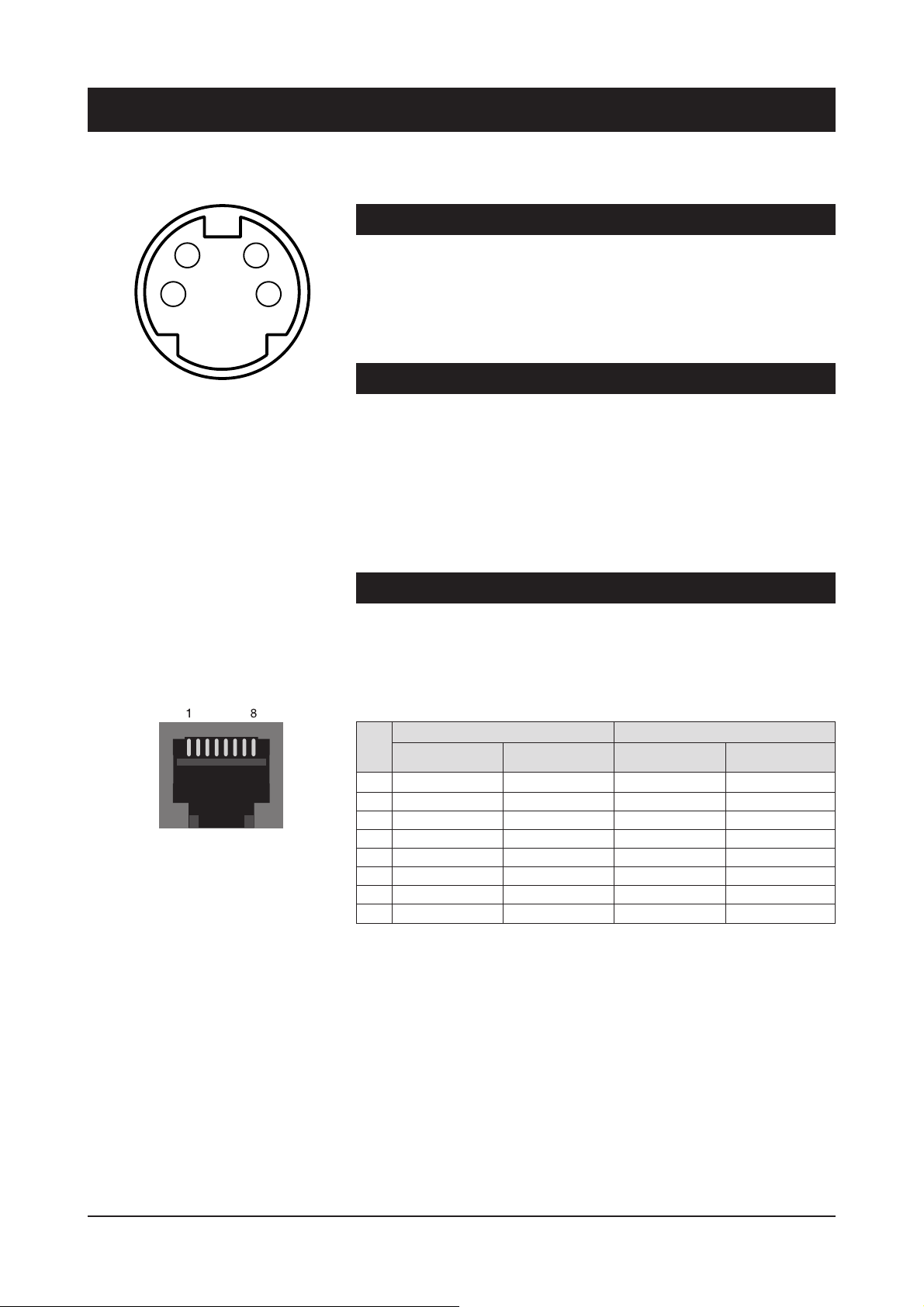
Picture 3. S-video connector
(4 pin min-DIN female).
Pin 1 - Ground (Y)
Pin 2 - Ground (C)
Pin 3 - Luminance (Y)
Pin 4 - Chrominance (C)
All products in EASI™ IP family have the same connection scheme in
their connectors. Depending on the model, there are Video, S-Video,
Audio, Data, Mgmt & Ethernet 100Base-TX connections.
Video,
audio, data and Ethernet port settings can be confi gured from web
user interface (WebUI) or command line interface (CLI).
Video Connection
The video connection provides one uni-directional video channel line
(BBE -- > BBD). The video connector is either type BNC female
(CVBS) or a 4 pin min-DIN female (S-video, see picture 3).
The impedance of the video (input/output is) 75 Ω. The nominal
input/output level is 1 Vpp.
When the Video connection status is OK, the “video” led on the front
panel is green. If the video signal is missing or it’s level is too low, the
“video” led is yellow.
Audio Connections
The audio connectors (1 & 2) provide one uni-directional audio
channel line (BBE -- > BBD). The audio impedance is constant and
cannot be adjusted. The audio input impedance is >10 kΩ and the
output impedance is <10 Ω. The connector is type RJ-45 female
(see picture 4 and table 1 for detailed description).
Audio
Picture 4. Audio connector.
BBE BBD
Pin
Audio 1 Audio 2 Audio 1 Audio 2
1 Ground Ground Ground Ground
2 Mgmt out Mgmt out
3 Ground Ground Ground Ground
4 out + out +
5 out - out 6 Mgmt in Mgmt in
7 in + in +
8 in - in -
Table 1. Audio connector’s pinout.
4 BLUEbox series user manual rev002
Page 7
Data
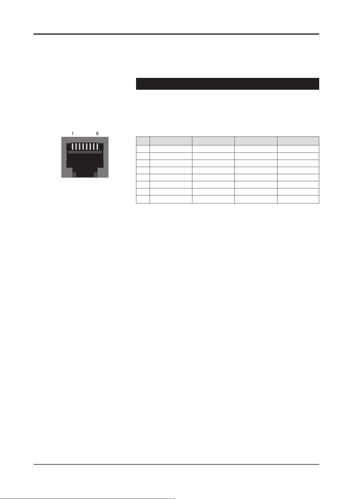
Picture 5. Data connector.
Data Connections
The data connectors (1, 2 & 3) provide one bi-directional data
channel (BBE <--> BBD). The data type can be set to RS232,
RS422, RS485-2w or RS485-4w. You can confi gure data settings
by help of WebUI or CLI. The connector is type RJ-45 female
(see picture 5 and table 2 for detailed description).
Pin RS232 RS422 RS485-2w RS485-4w
1 out + in / out + out +
2 out out - in / out - out 3 in - in / out - in 4
5 Ground Ground Ground Ground
6 in in + in / out + in +
7
8 Ground Ground Ground Ground
Table 2. Data connector’s pinout and supported data types.
BLUEbox series user manual rev002 5
Page 8
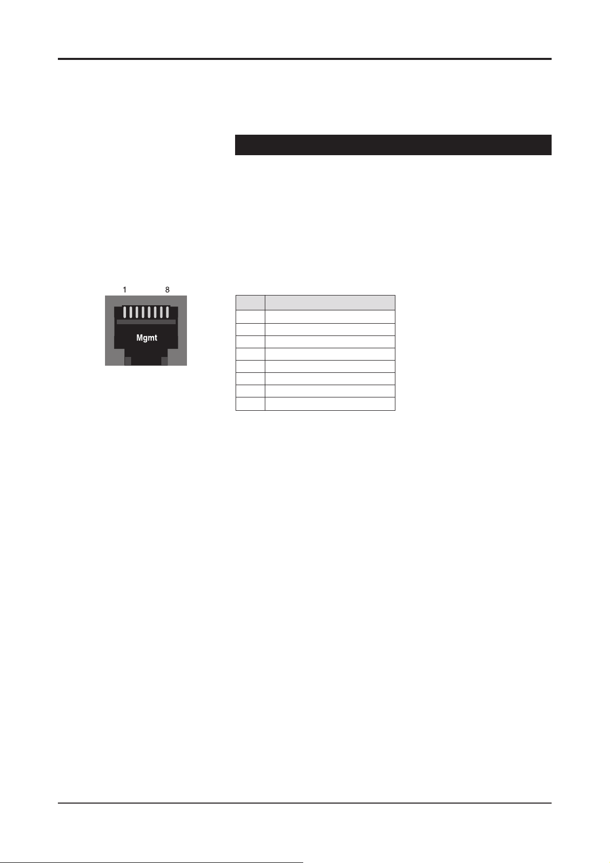
Picture 6. Management connector.
Management Connection
The Mgmt (Management) connector provides one bi-directional data
channel (RS232). The Mgmt connection is meant for confi guration
and controlling of BLUEbox devices locally by CLI. Management
connection between BLUEbox devices and e.g. laptop is based on a
serial data communication by means of any terminal type program
(e.g Windows Hyper Terminal). Management software for BLUEbox
devices is a Command Line Interface (see page 21 for detailed
description). The Mgmt connector is type RJ-45 female (see picture
6 and table 3 for detailed description). The management cable is
type CIC504 (see table 7 on page 8 for pinouts).
Pin Signal
1
2 Mgmt out
3
4
5 Ground
6 Mgmt in
7
8 Ground
Table 3. Mgmt connector’s pinout.
6 BLUEbox series user manual rev002
Page 9
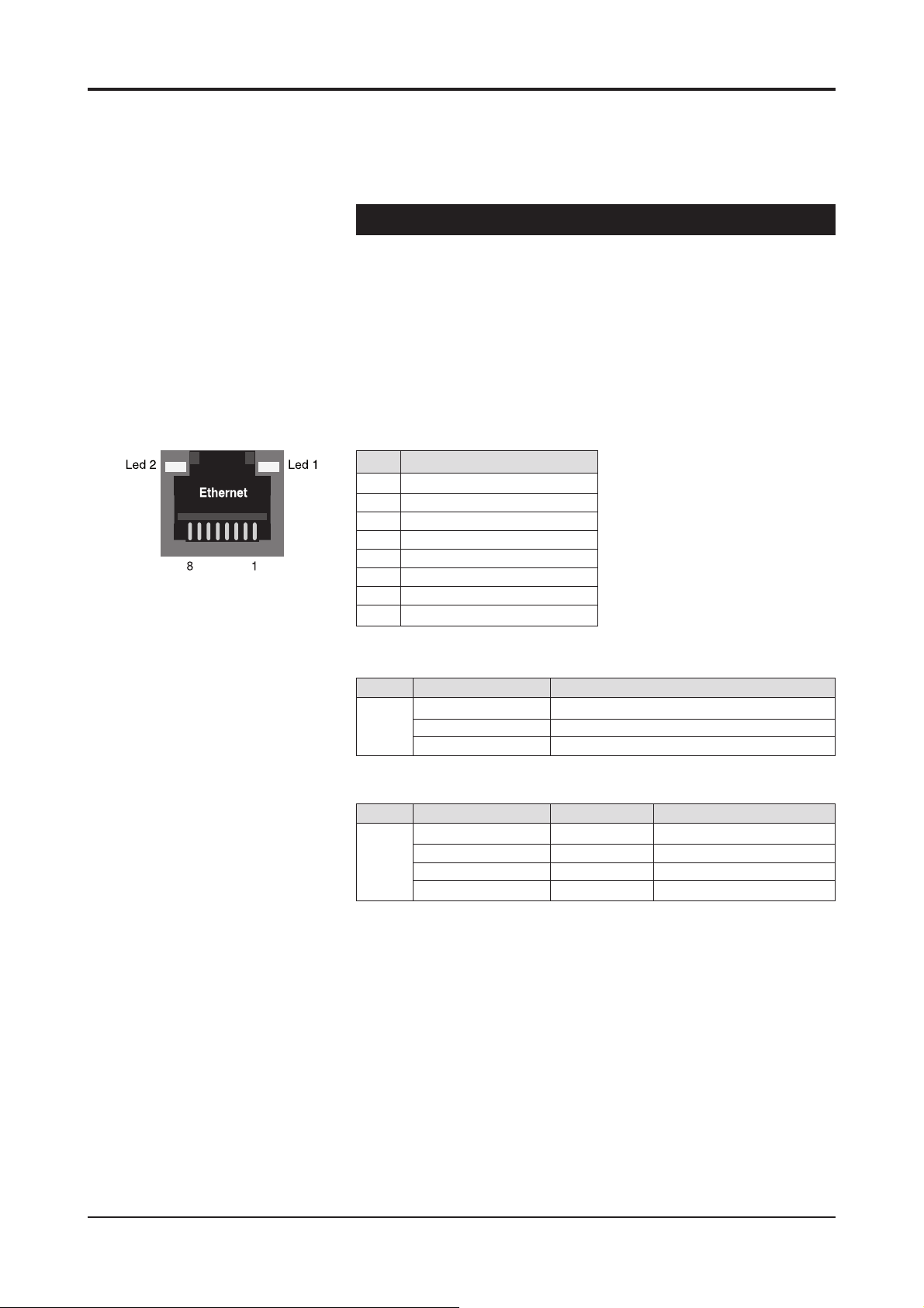
Picture 7. Ethernet connector (CAT5).
Ethernet Connection
The Ethernet connector provides 10 /100Base-TX Ethernet network
interface. The connector is type RJ-45 female (CAT5, see picture 7
and table 4 for detailed description).
When the Ethernet connection status is OK, the “link” led on the
front panel is green. If the Ethernet signal is missing or it’s level is too
low, the “link” led is yellow.
Note! It is also possible to create Web User Interface (WebUI)
connection locally into the device via this Ethernet connector.
Pin Signal
1 Tx +
2 Tx 3 Rx +
4
5
6 Rx -
7
8
Table 4. Ethernet connector’s pinout (CAT5).
Led Colour Ethernet signal
1 Yellow On stream
Blinking yellow Interface up
Dark Signal is missing or it’s level is too low
Table 5. Ethernet connector (RJ-45) / led 1 indicator lights.
Led Colour Speed Mode
2 Green 100 Mbps Full Duplex
Blinking Green 100 Mbps Half Duplex
Orange 10 Mbps Full Duplex
Blinking orange 10 Mbps Half Duplex
Table 6. Ethernet connector’s led 2 / indicator lights.
BLUEbox series user manual rev002 7
Page 10

How to change the settings
General
This chapter tells how you can confi gure and check the settings of
BLUEbox device with help of web user interface (WebUI) or
command line interface (CLI).
Web User Interface (WebUI)
Teleste’s WebUI provides an user friendly way to confi gure and
manage BLUEbox device. WebUI session can be accessed using
Internet browser such as Internet Explorer. See next page for
detailed description.
Command line interface (CLI)
Teleste’s BLUEbox device includes also a text-based user interface
(CLI) for confi guration purposes.
System Requirements:
* PC equipped terminal emulation program e.g. Hyper Terminal
(supporting VT100 / 102 or ANSI protocols).
* RS232-cable (type Teleste CIC504), see table 7 for cable pinout
* Cross-connected Ethernet cable (e.g. Teleste OPUS1CCC0050X
when using TCP/IP connection).
CLI is accessed Locally via Mgmt connector with a serial connection
cable (CIC504) and any terminal emulation type program (e.g. Hyper
Terminal) or Remotely via TCP/IP connection (e.g. Telnet).
The command structure is the same for both session types.
See page 21 for detailed description.
PC/PSION D9 female RJ-45 male BLUEbox
Receive data 2 2 MGMT output
Transmit data 3 6 MGMT input
System ground 5 1 Ground
Table 7. RS232 cable (CIC504) pinout (D9 female / RJ-45 male).
User groups
There are four different groups of authority, which are determined by
the username and password (see table 8). The username and
password can be change: CLI confi g level (page 26) and
WebUI (page 17).
User Group Default Default Authority
Username Password
guest guest guest
technician tech tech
operator oper oper
administrator admin admin
Read only access to general pages
Read only access to all pages
Read and write access to all pages
and operational settings
Read and write access to all pages
and all settings
Table 8. User groups
8 BLUEbox series user manual rev002
Page 11

Web User Interface (WebUI)
Introduction
This chapter tells how to confi gure the settings using web
user interface.
General
The BLUEbox Encoders (BBE) and the BLUEbox Decoders
(BBD) are fully controllable with the Web User Interface (WebUI).
System Requirements:
* The PC equipped with an Ethernet Network card and an
Internet browser installed.
* Cross-connected Ethernet cable
(e.g. type OPUS1CCC0050X).
You can access the Web User Interface locally via Ethernet
connector or remotely over an TCP/IP Ethernet connection.
Operation
Web User Interface window consists of several pages. Only one
page is completely visible at one time. You can activate a page
simply by clicking the page’s heading (see picture 10).
The Web User Interface has the following confi guration display
pages that are introduced in this document:
- General Information
- Network Confi g
- Confi guration
- Video Management
- SAP Management
- Statistics (video statistics, only in BLUEbox Decoder)
- Change Password
- User Management
- Services
- Data Channel 1
- Data Channel 2
- Data Channel 3
- Statistics (data channel statistics)
The information on confi guration sheets is shown in data fi elds
or boxes. You can change settings in data fi elds or boxes whose
background is white. Place your cursor in the desired data fi eld or
box and enter the new setting. Some settings are entered by
ticking a checkbox or clicking on a radio button, by selecting from
a pull-down list or by scrolling digits with the help of spin buttons.
Information without datafi eld or box is read only parameter and
can not be change.
BLUEbox series WebUI user manual rev002 9
Page 12
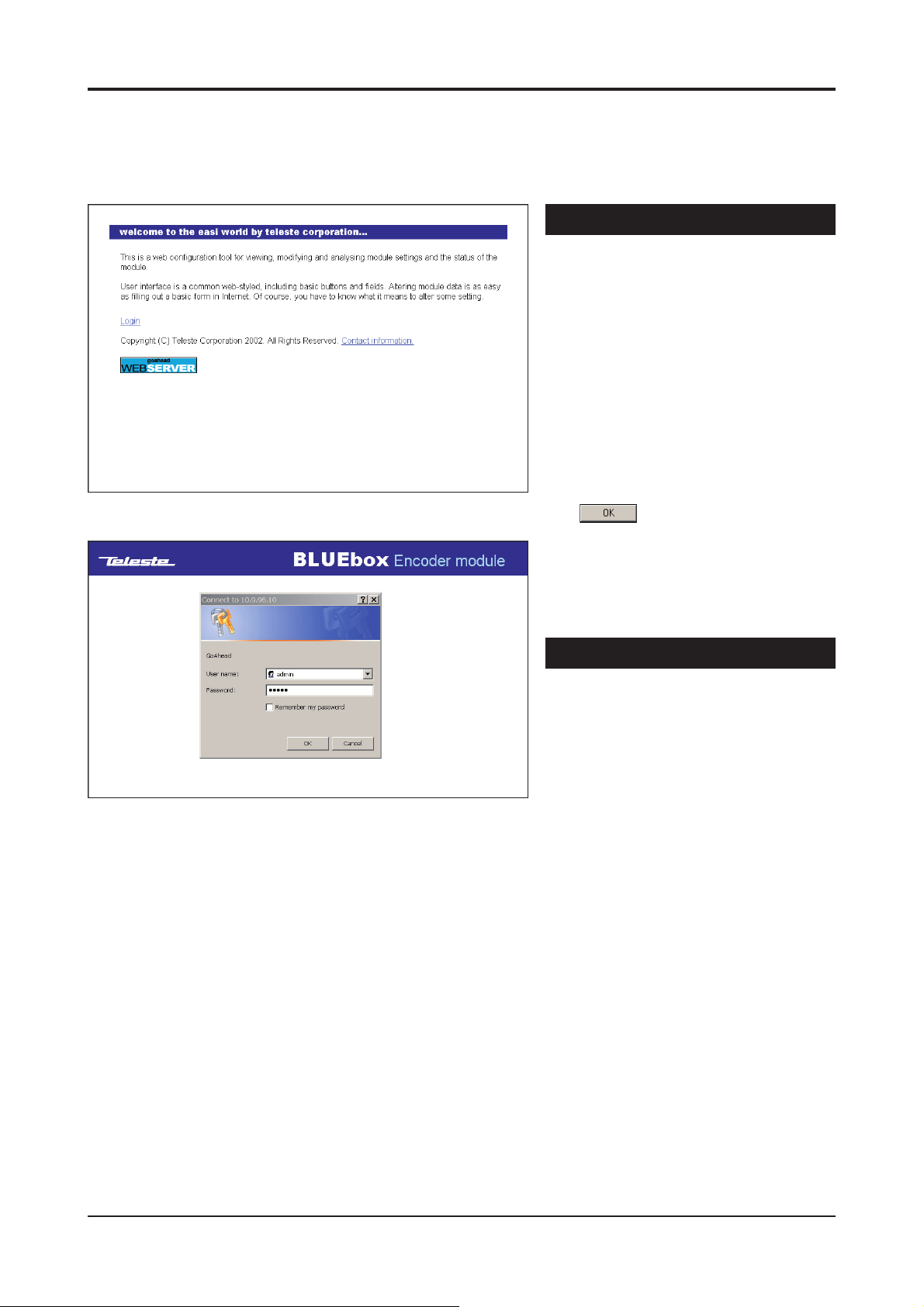
Picture 8. Web User Interface’s start page.
Starting
To create the WebUI session to the
device, fi rst enter device’s IP address into
the web browser’s address.
Encoder’s default factory IP address is
10.9.96.10 and Decoder’s default factory
IP address is 10.9.96.20.
The following Web User Interface’s start
page will appear on the screen
(picture 8).
Click login to continue --> “Enter Network
Password” window appears on the screen
(picture 9).
Write the required username and
password in the fi elds and then
click OK button to continue --> Web
User Interface’s “General Information”
page appears on the screen
(picture 10 & 11).
The Web User Interface session to
BLUEbox device is now completed.
User Groups for WebUI
Picture 9. Authorization window.
There are four different groups of
authority, which are determined by the
username and password
(see table 8 on page 8 for User groups).
The username and password can be
change on Administration page
(page 17).
10 BLUEbox series WebUI user manual rev002
Page 13
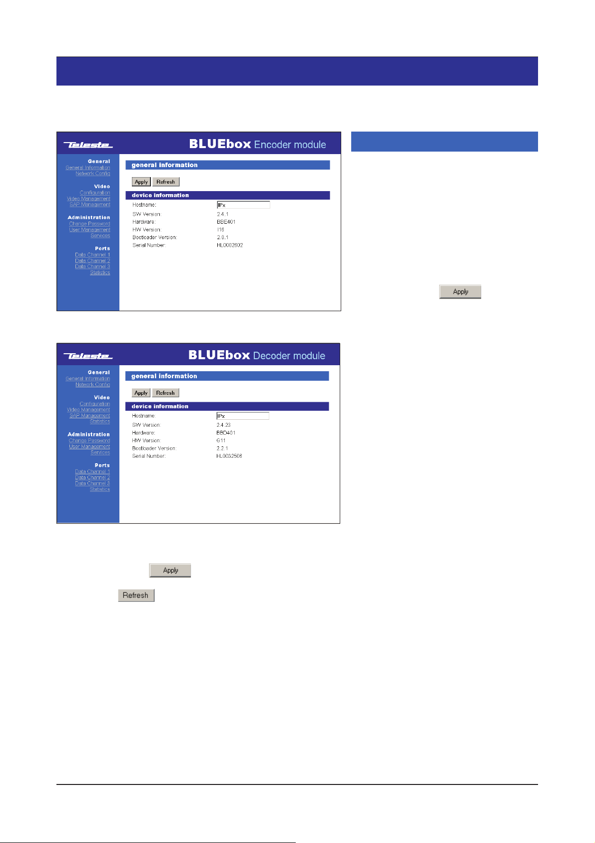
General
General information
Click heading “General Information”
under the General menu on the left
column. General information / device
information window appears on the right
side of page (picture 10 & 11). On this
page you can see device’s general
settings and change device’s hostname.
Picture 10. General information page (BBE).
Picture 11. General information page (BBD).
Hostname:
the device (uniquely identifi es each device
of a network). Click ppl button to
confi rm a hostname for the device
SW Version: Device software version
Hardware: Device hardware type
HW Version: Device hardware version
Bootloader Version: Device
bootloader version
Serial Number: Device serial number
User defi nable alias name for
Note! Always click Apply button to activate settings.
Note! Click Refresh button to update the page view.
BLUEbox series WebUI user manual rev002 11
Page 14
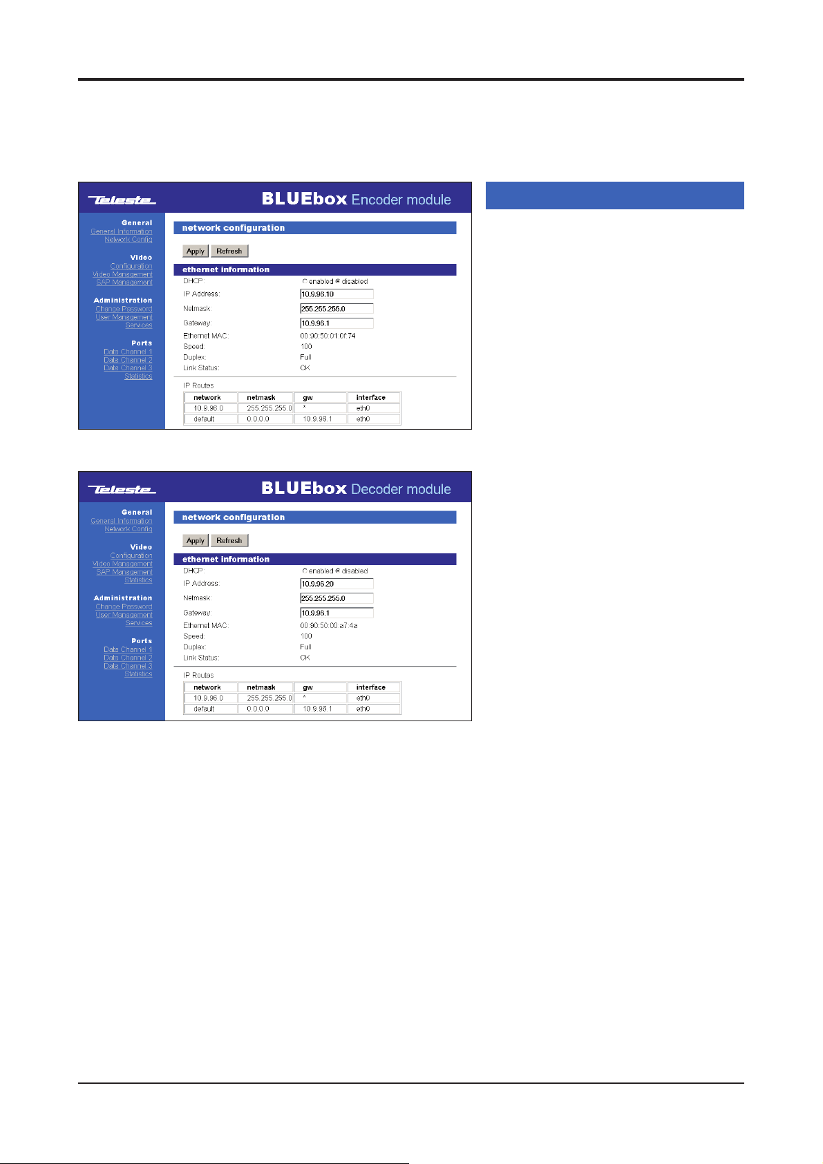
Picture 12. Network confi g page (BBE).
Network confi guration
Click heading “Network Confi g” under
the General menu on the left column.
Network confi guration / ethernet
information window appears on the
right side of page (picture 12 & 13).
On this page you can see and change
device’s Ethernet network settings.
DHCP: DHCP server operation enabled/
disabled. If enabled, the device gets its IP
address from the DHCP server.
IP Address: IP address of device.
Note! If this is changed, a new contact
with the new IP address must be
assigned to be able to continue with
WebUI session.
Netmask: Mask for subnet defi nition.
Gateway: Gateway address for router
defi nition. Gateway address is necessary
for multicasting video. Device and
gateway addresses should be in the
same network.
Note! Gateway address should be set
before enabling multicast video.
Picture 13. Network confi g page (BBD).
Ethernet MAC: Device MAC address.
Speed: Network connection speed.
Duplex: Network connection type
(half / full).
Link Status: Network connection status.
OK indicates that network connection
works and error indicates that network
connection does not work.
IP Routes:Network parameters
(see glossary for detailed descriptions).
network:
netmask:
gw:
interface:
12 BLUEbox series WebUI user manual rev002
Page 15
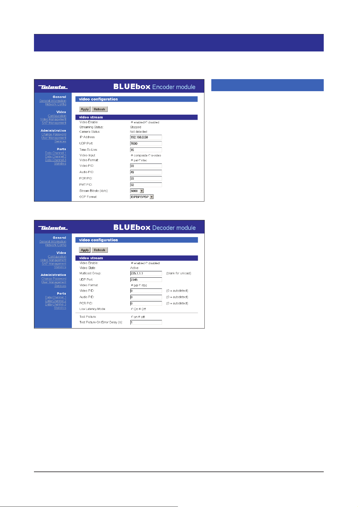
Video
Picture 14. Video confi guration page (BBE).
Video confi guration
Click heading “Confi guration” under the
Video menu on the left column.Video
confi guration / video stream window
appears on the right side of page
(pictures 14 & 15).
On this page you can modify device’s
video interface confi guration.
Video Enable:
BBE: Sets video encoding enable / disable
BBD: Sets video decoding enable / disable
Streaming Status:
(OK/stopped/invalid confi guration/error)
Camera Status: Video indicator (BBE).
(OK/not detected)
Video State: Video indicator (BBD).
(active/waiting/inactive/error)
Video indicator (BBE).
Picture 15. Video confi guration page (BBD).
Test Picture: Internally generated test picture
enabled / disabled (BBD).
Test Picture On Error Delay (s): Test picture
activating time in seconds when decoded video
is corrupted or missing.
* In multicast case there should be same IP address /
multicast group for video in Encoder and Decoder device.
Gateway address is necessary for multicasting video
(see Network confi guration / Gateway, page 12).
Note! The gateway address should be set before enabling
the multicast video.
IP Address:
BBE: In multicast case, see note*. In
unicast video case, the IP address should
be receiving decoder device’s
BBD:
In multicast case, see note*. In
unicast video case, the fi eld should be blank
UDP Port: UDP port number. This number
has to be same at both encoder and
decoder pairs
Multicast TTL: “Time to live” value, can
be set 1 to 255 (BBE)
Video Input: Video input type, either
composite (CVBS) or S-video (BBE)
Video Format: Video format type, either
PAL or NTSC
Video PID: MPEG-2 video PID value.
This number has to be same at both
encoder and decoder pairs
Audio PID: MPEG-1 Audio PID value.
This number has to be same at both
encoder and decoder pairs
PCR PID: MPEG-2 PCR PID value
PMT PID: MPEG-2 PMT PID value (BBE)
Low Latency Mode: Video latency
setting. When enabled it reduces the
switching time between different video
sources (i.e.: camera touring). When
disabled it improves video-audio
synchronization. (BBD)
Stream Bitrate: Encoded video bitrate,
selectable 3, 4, 5, 6, 7, 8, 9 & 10 Mbps (BBE)
GOP Format: MPEG-2 GOP format,
selectable I, IP, IBP, IBBP (BBE)
BLUEbox series WebUI user manual rev002 13
Page 16
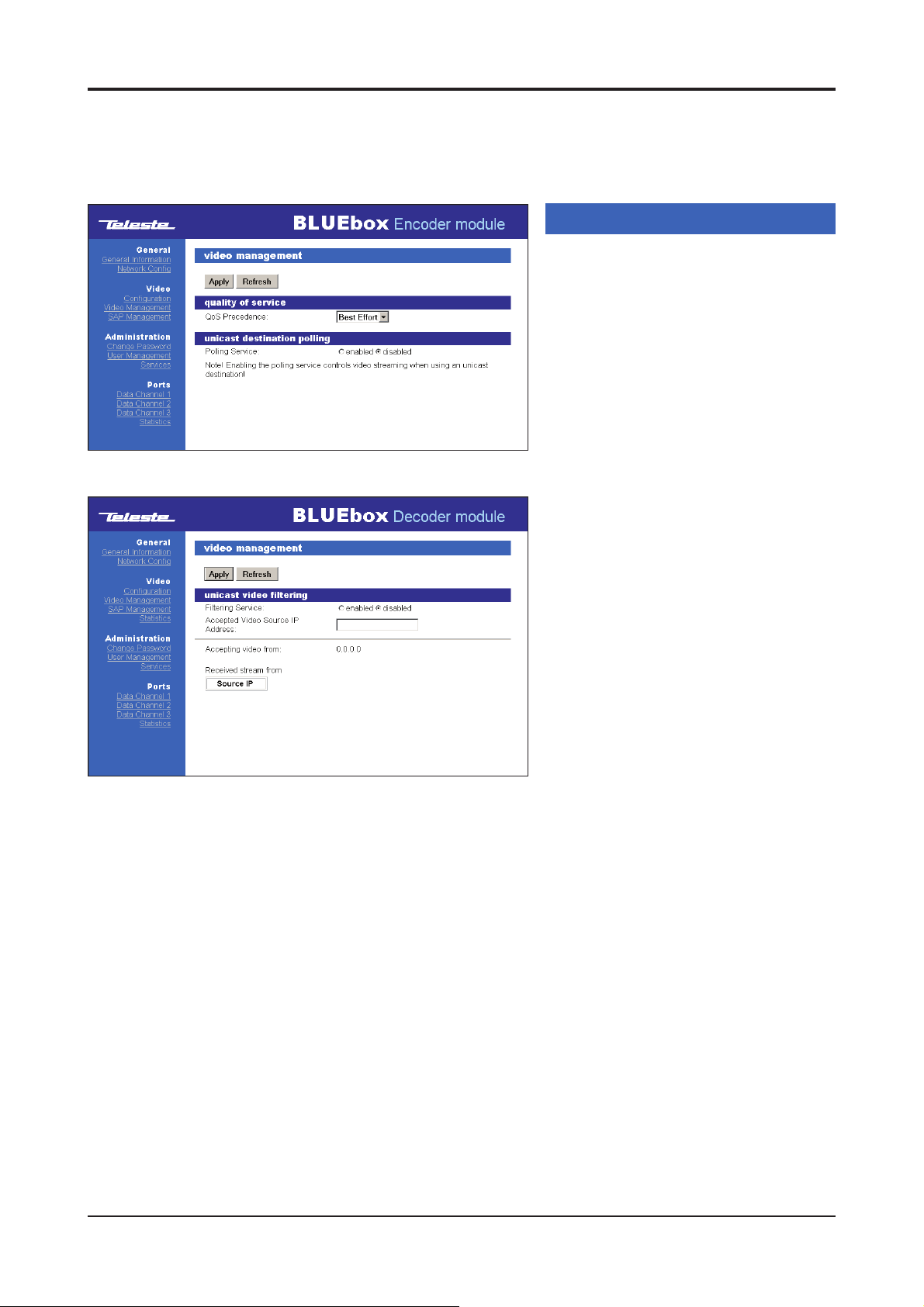
Picture 16. Video management page (BBE).
Picture 17. Video management page (BBD).
Video management
Click heading “Video Management”
under the Video menu on the left column
of page.
service (when BBE) / unicast video fi ltering
(when BBD) window appears on the right
side of page (pictures 16 & 17). On this
page you can modify device’s video Qos
and unicast video settings:
BBE:
QoS Precedence: Quality of service
level selection (class 0...4, best
effort=class 0)
Polling Service:
disabled. This is needed to be enabled at
all BBE encoders which are transmitting
the unicast video to the same BBD
decoder. Respectively, the unicast fi ltering
must be enabled on BBD decoder
BBD:
Filtering Service: Filtering service
enabled/disabled. When enabled, the
BBD decoder will be locked to the fi rst
received unicast video stream.
Respectively, the unicast fi ltering must be
enabled on BBE encoder
Accepted Video Source IP Address:
Defi ned source IP address. If left empty,
the BBD decoder will be locked to the fi rst
received video stream
Accepting video from: Actual source
IP address
Received stream from: List of available
sources IP addresses
Video management / quality of
Polling service enabled/
14 BLUEbox series WebUI user manual rev002
Page 17
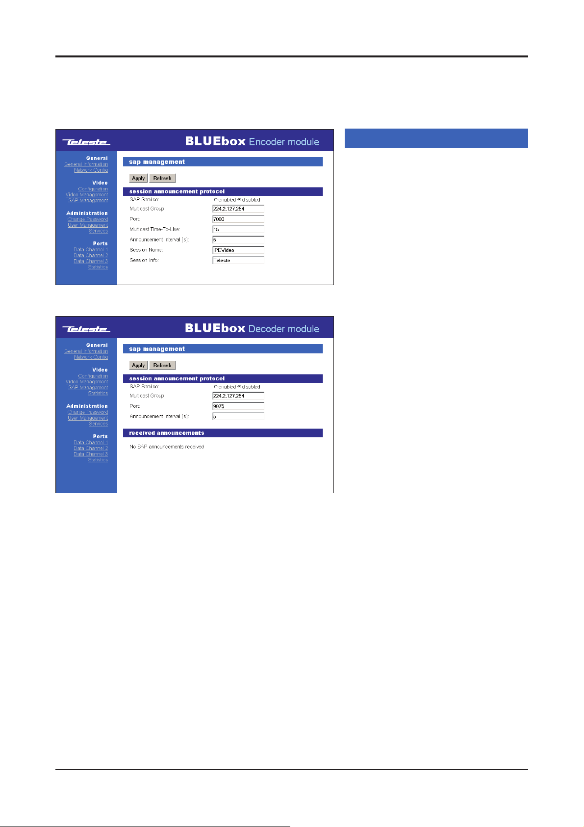
Picture 18. SAP management page (BBE).
Picture 19. SAP management page (BBD).
SAP management
Click heading “SAP Management” under
the Video menu on the left column of page.
Sap management / session announcement
protocol window appears on the right side
of page (picture 18 & 19). On this page you
can modify device’s session
announcement protocol settings:
SAP Service: Service enabled / disabled
Multicast Group: SAP advertisements
global scope address as described in
RFC 2974. Default IP = 224.2.127.254
Port: SAP advertisements IP port number
as described in RFC 2974.
Default port = 9875.
Multicast Time-To-Live: SAP
advertisements number of hops between
routers. Should be 255 as described in
RFC 2974 (only in BBE)
Announcement Interval (s): SAP timing
in seconds. Retransmit time of SAPpacket. This time has to be same at both
encoder and decoder pairs
Session Name: The name of the stream
associated with SAP-packet. This name
shows at the decoders SAP page
(only in BBE)
Session Info: Owner of the stream.
User can use own ID to detect ownership
of the stream. SAP application fi lls the
rest of the string (with user Id IPE12345
eg. IPE12345 IN IP4 xxx.xxx.xxx.xxx)
(only in BBE)
Received announcements: Display
received SAP announcements
(only in BBD)
BLUEbox series WebUI user manual rev002 15
Page 18
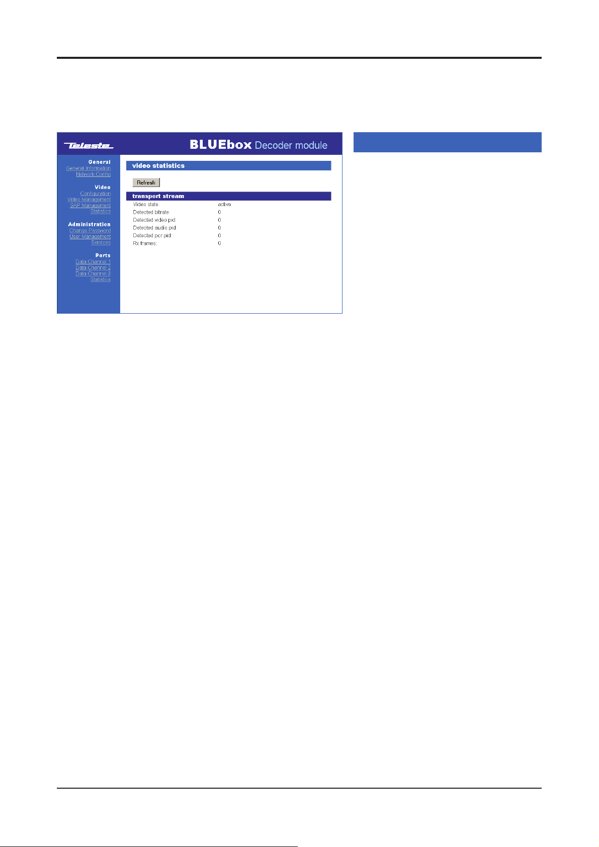
Picture 20. Video statistics page (only in BBD).
Video statistics (only in BBD)
Click heading “Statistics” under the
Video menu on the left column.
Video statistics / transport stream window
appears on the right side of page
(picture 20). On this page you can see
BBD device’s video stream settings.
Video state: Display received video state
(active/waiting/inactive/error)
Detected bitrate: Display received
video bitrate.
Detected video Pid: Display received
video pid value.
Detected audio pid: Display received
audio pid value.
Detected pcr pid: Display received pcr
pid value.
Rx frames: Display total number of
received frames.
16 BLUEbox series WebUI user manual rev002
Page 19
Administration
Change password
To change the password, fi rst click
heading “Change Password” under the
Administration menu on the left column.
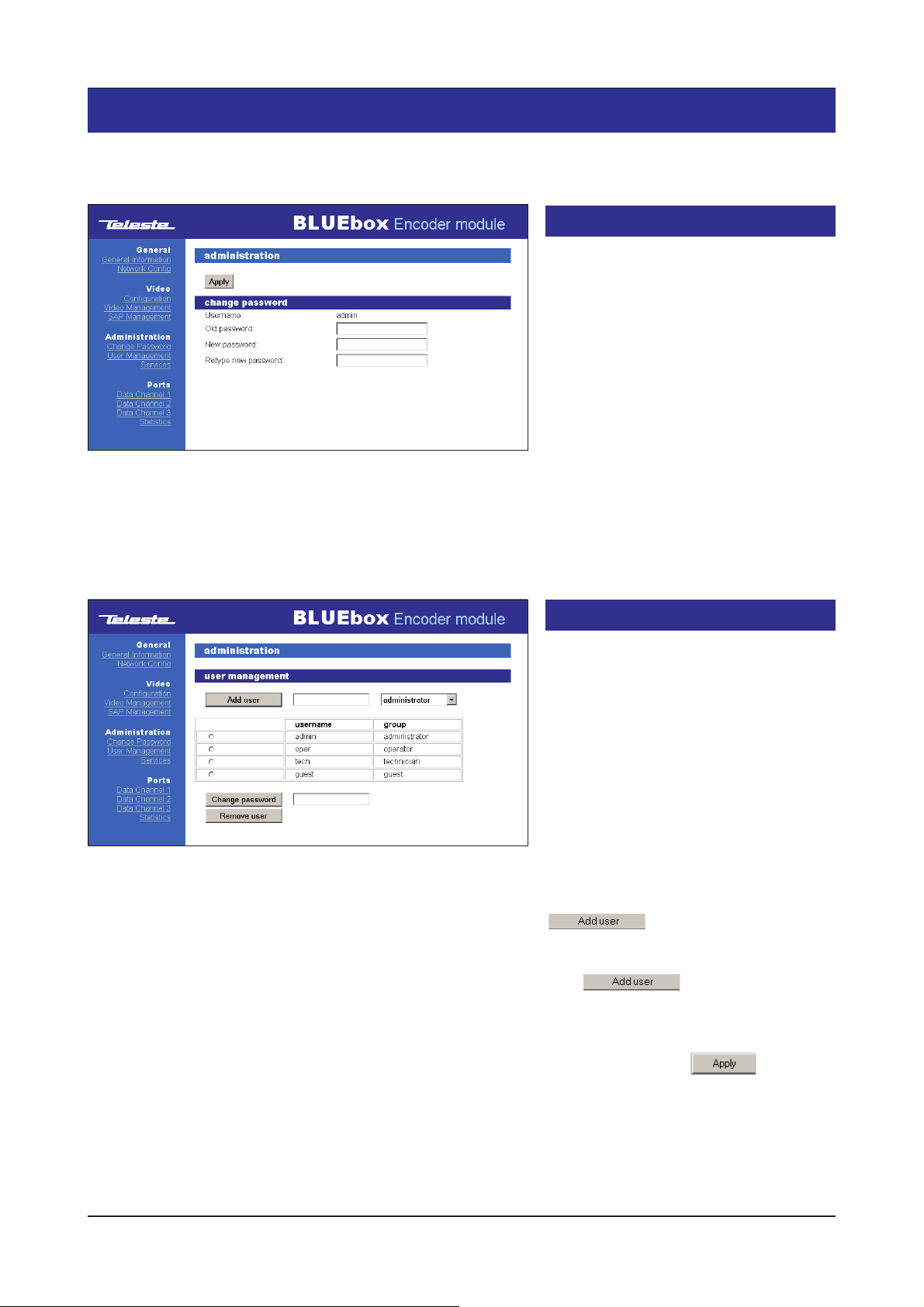
Administration / change password
window appears on the right side of page
(picture 21). On this page you can change
your username and password.
Note! Use only characters and numbers.
Do not use special characters!
Picture 21. Change password page (BBE).
Picture 22. User management page (BBE).
Username: Username of which you are
logged in to the interface.
Old Password: Current password.
New Password: New password.
Retype New Password: Verifi cation of
the new password.
User management
To access user management functions,
admin level access rights are needed.
To change the user information, fi rst click
heading “User Management” under the
Administration menu on the left column.
Administration / user management
window appears on the right side of page
(picture 22).
On this page you can add/remove users
and change their passwords.
To add a new user,
fi rst type the desired user name next to
button (picture 22).
Select the desired user group from pulldown list on right side.
Click button to activate the
new user.
The new user will appear on the user list.
Note! Always click Apply button to
activate settings.
BLUEbox series WebUI user manual rev002 17
Page 20
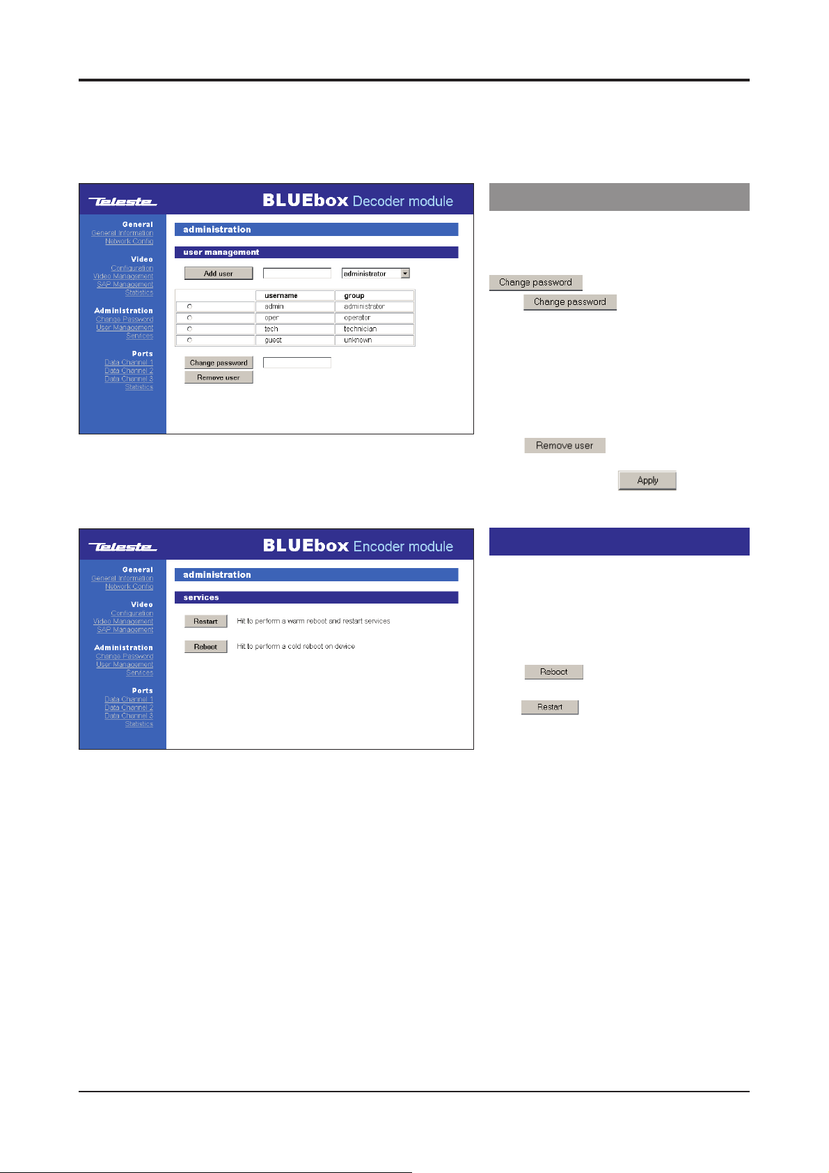
Picture 23. User management page (BBD).
To change the user password
First select user from users list by ticking
the checkbox before the username.
Write new password to the box after
button.
Click button to activate
the new password.
Note! Use only characters and numbers.
Do not use special characters!
To remove the user,
fi rst select the user from users list by
ticking the checkbox before username.
Click button to remove user.
Note! Always click Apply button to
activate settings.
Services
To reboot or restart the device, fi rst
click heading “Services” under the
Administration menu on the left column.
Administration / services window appears
on the right side of page (picture 24).
Click button to reboot the
device (this takes 90 seconds).
Click button to restart the device.
Picture 24. Services page (BBE).
18 BLUEbox series WebUI user manual rev002
Page 21
Data ports
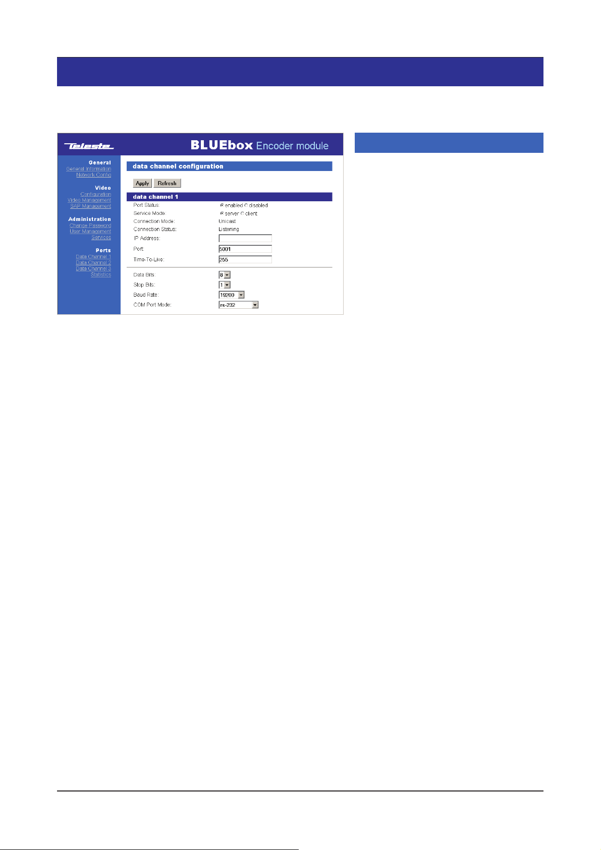
Picture 25. Data channel 1 confi g page (BBE RS232 example).
Example of one data channel confi guration
Multicast:
BBE
Service Mode:
IP Address: 225.1.1.2
Port: 5001
BBD
Service Mode:
IP Address: 225.1.1.2
Port: 5001
Unicast:
BBE
Service Mode: Server
IP Address: Blank or BBD’s IP address*
Port: 5001
BBD
Service Mode: Client
IP Address: 10.9.96.10 (BBE device IP address,
see from BBE’s Network confi g page)
Port: 5001
* If set blank, the point-to-point connection will be locked
between BBE (server) and the fi rst connected BBD (client)
device. Guaranteed point-to-point unicast connection
between BBE and BBD devices is established when there
is set BBD’s IP address.
Data channel confi guration
Click heading Data channel 1, 2 or 3
under the Ports menu on the left column.
Data channel confi guration / data channel
1, 2 or 3 window appears on the right side
of page
On these pages you can change data
channel 1...3 settings. All data channels
operates independently and have their
own settings:
Port Status: Choose enabled when data
channel is taken in use. Disabled if data
channel is not in use
Service Mode:
transmission is established by enabling the
“server” and “client” settings between the
data ports (always make sure that one
device is set to “server” and the other
device is set to “client”). If data is
transmitted in multicast mode, service
mode is detected automatically
Connection Mode: TCP connection
mode (unicast / multicast)
Connection Status: TCP connection
status (established / waiting / fail)
IP Address: Data IP address, see
example on the left
Port: TCP port value. This number has to
be same at both client and server pairs
Time-To-Live:
value, can be set 1 to 255
Data Bits: Byte length. Options are 5, 6,
7, 8 & 9. The default value is 8
Stop Bits: Options are 1 or 2. The default
value is 1
Baud Rate: Datachannel connection
speed (range 1200...115 200 bps)
COM Port Mode: Connection protocol
towards the external device
(RS232/422/485 2-wire/485 4-wire)
(e.g. picture 25 for data channel 1).
Point-to-point type data
IP packets “Time to live”
Note! In case of using parity bits, they
must be included here!
(i.e. 8 x data + 1 x parity = 9)
BLUEbox series WebUI user manual rev002 19
Page 22
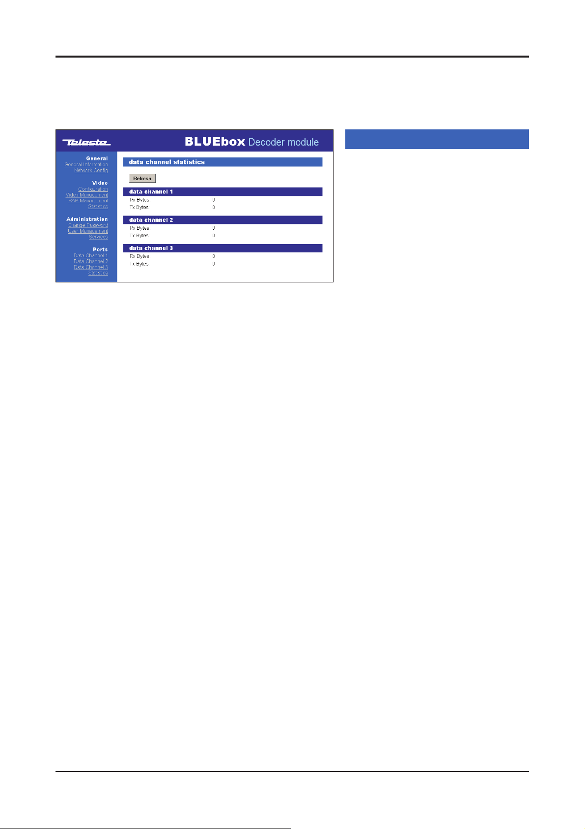
Picture 26. Data channel statistics page (BBD).
Data channel statistics
Click heading “Statistics” under the Ports
menu on the left column.
Data channel 1, 2 and 3 statistics window
appears on the right side of page
(picture 26).
Rx bytes: Number of bytes received
since the last counter reset (start-up).
Tx bytes: Number of bytes transmitted
since the last counter reset (start-up).
20 BLUEbox series WebUI user manual rev002
Page 23
Command Line Interface - CLI
Connection methods - Hyper Terminal
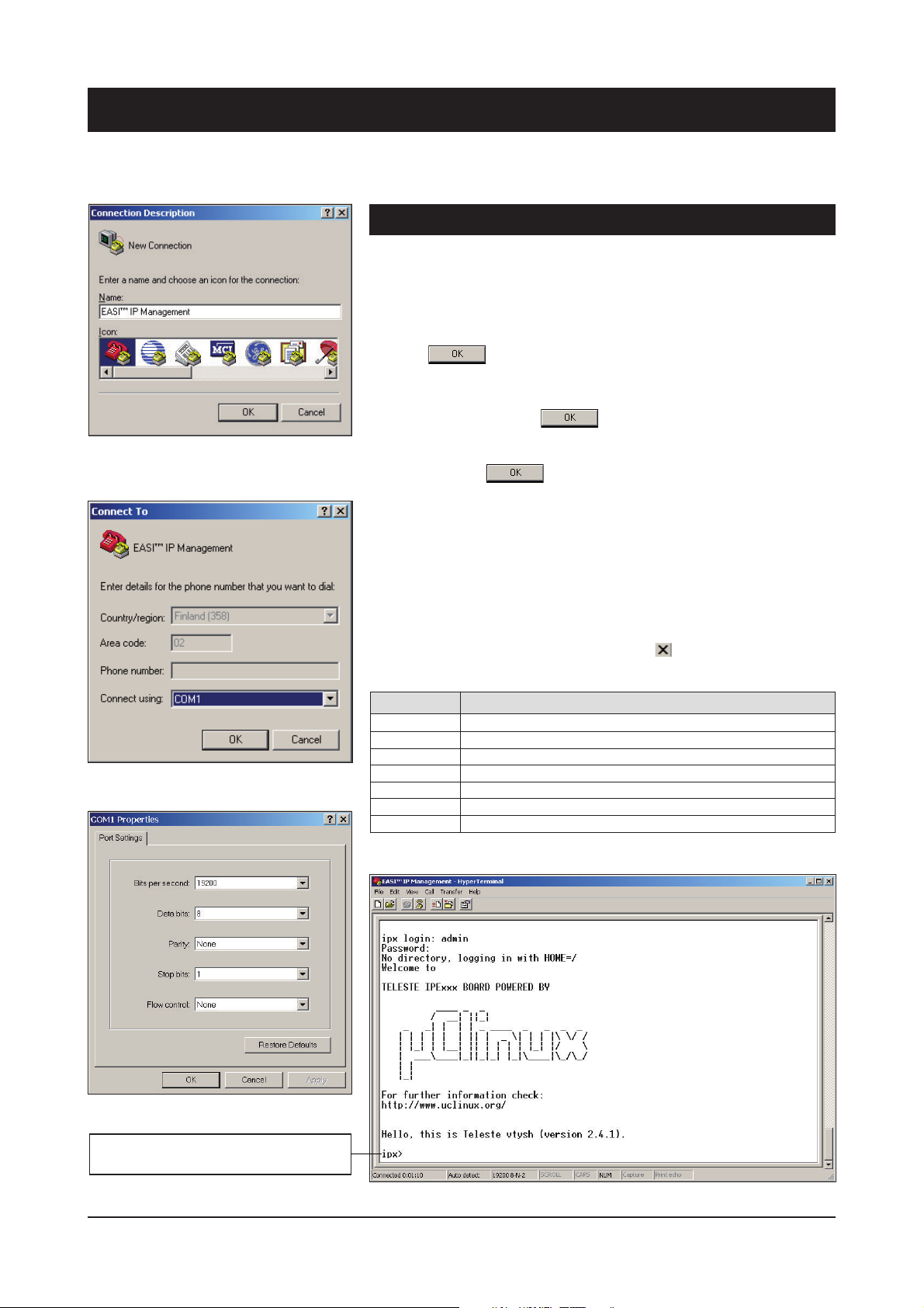
1. Start the Windows Hyper Terminal program (in Windows by
choosing -> Start/Programs/Accessories/Communications/
Hyper Terminal). Wait until the following “Connection
Description” window appears on the screen (see picture 27).
2. Enter a name for connection, e.g. “EASI™ IP Management” and
click OK button to continue. The following “Connect To”
window appears on the screen (see picture 28).
3. Choose COM port where the RS232 cable is connected, e.g.
COM1 port and click OK button to continue.
The following “COM1 Properties” window appears on the
Picture 27. Naming a terminal
connection.
screen (see picture 29). Set here the values as described in
table 9. Click OK button to continue.
The “EASI™ IP Management” window appears on the screen
(like picture 30 without text).
4. To activate the terminal connection fi rst press Enter -->
“ipx login:” appears on the screen. Enter the required user
name and the password
The terminal connection to BLUEbox device is now completed
and you can now use the CLI commands to management the
device. The Hyper Terminal connection can be terminated by
selecting File/Exit, Alt+F4 or clicking x on the right upper
corner of Hyper Terminal window.
(see table 8 on page 8 for User groups).
Picture 28. Selecting COM port.
Picture 29. Settings for COM port.
When the CLI is activated, “ipx>”
text appears on the screen.
Setting Value
Emulation VT100, VT102 or ANSI
Protocol Serial
Baud rate 19200
Data bits 8
Parity None
Stop bits 1
Flow control None
Table 9. Port settings to terminal connection.
Picture 30. The Windows Hyper terminal program’s window view.
BLUEbox series CLI user manual rev002 21
Page 24
Connection methods - Telnet
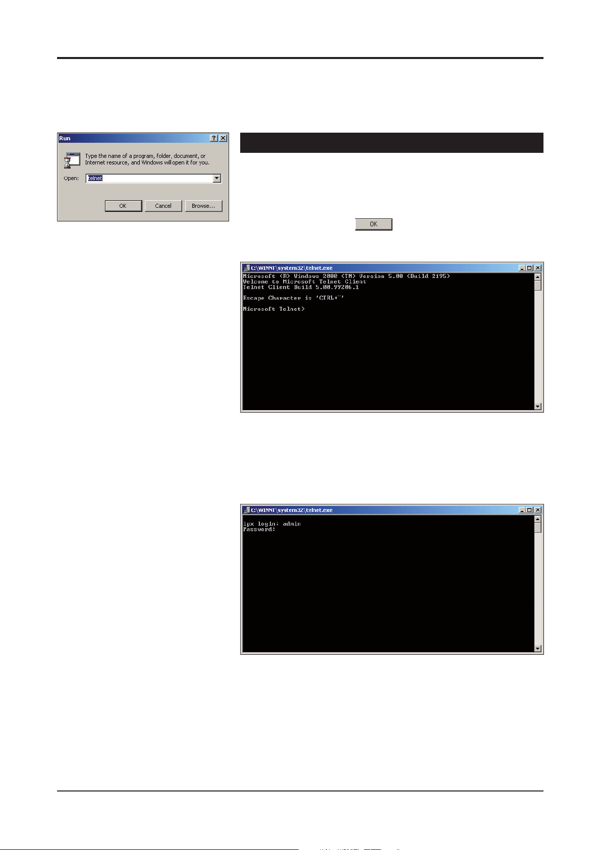
1. Start the Run utility program (in Windows by choosing ->
Start/Run...).
Wait until the following “Run” window appears on the screen
(see picture 31).
Picture 31. Run utility program view.
2. Write Telnet and click button to continue.
The following “Telnet.exe” window appears on the screen
(picture 32).
Picture 32. Telnet program view.
3. Enter the following command to the Telnet prompt:
open [IP address], where the IP address is the target
device’s IP address.
The following “Telnet.exe /ipx login:” window appears on the
screen (picture 33).
Picture 33. Telnet program view.
4. Enter the required user name and the password
(
see table 8 on page 8 for User groups)
The Telnet connection to BLUEbox device is now completed
and you can now use the CLI commands to controlling the
device. The Telnet display is identical of local CLI view and
as well the command structure follows the same rules as
local CLI connection.
5. The Telnet connection can be terminated by entering
command quit.
.
22 BLUEbox series CLI user manual rev002
Page 25
How to use the CLI
CLI levels
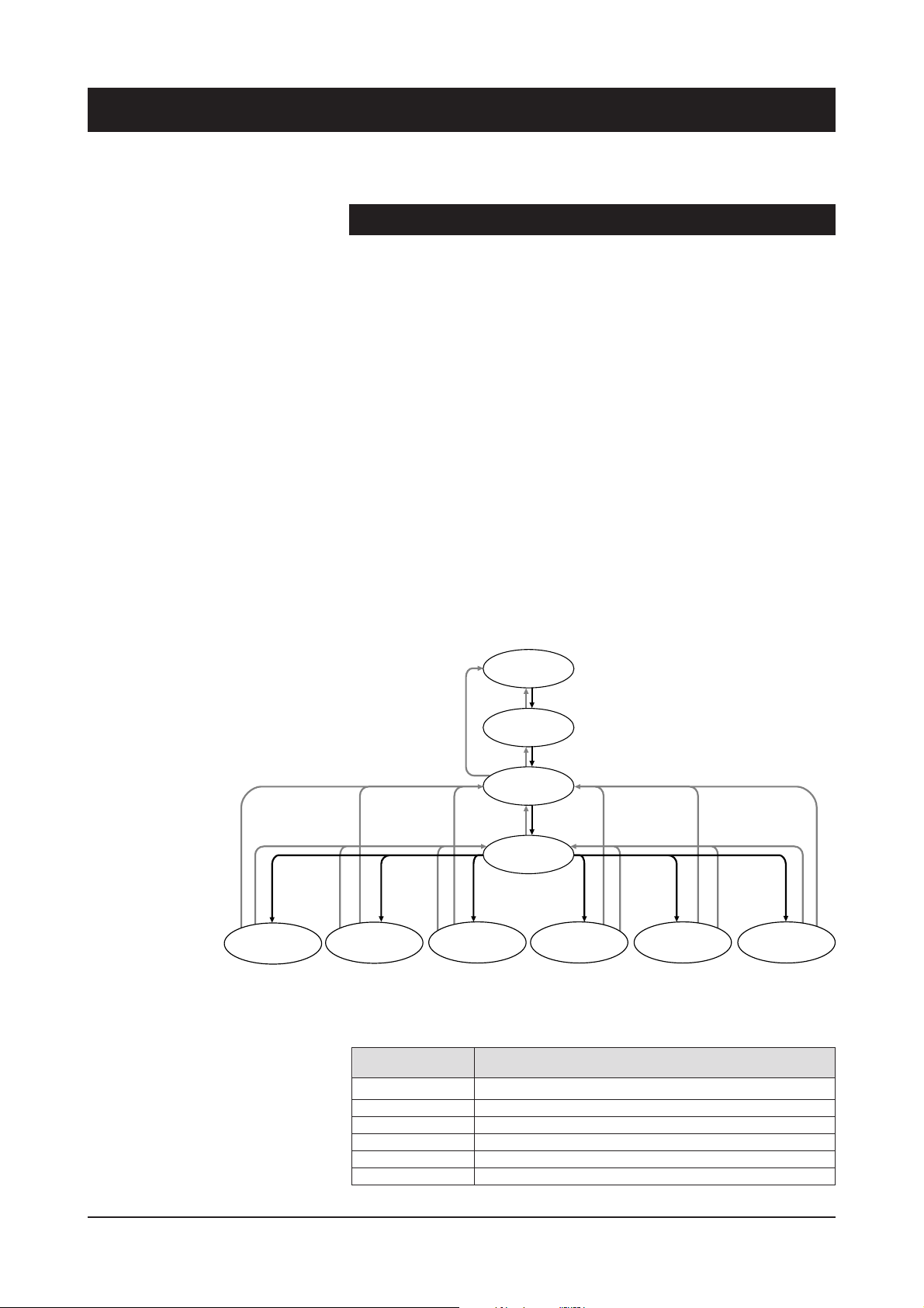
CLI consists of several levels. You can move from one level to other by
step by step.(See picture 34 and table 10 for detailed description).
To execute the command, press enter after typing command.
Instead of writing complete command, you may use shortenings such
as quit = q and confi g terminal = c t. To separate commands having
same initial letter(s), the shortening must be more specifi c by adding
more command’s letters, e.g. end = en and exit = ex.
The CLI levels are:
- Disable (Basic level)
- Enable (Settings viewing level)
- Confi g (Administer level)
- Confi g-if (Data settings editing level)
- Confi g-if (Ethernet port settings editing level)
- Confi g-sap (SAP settings editing level)
- Confi g-ts (Video/audio settings editing level)
-
Confi g-fi lter (Unicast video settings editing level, only in BBD)
- Confi g-line (Terminal view settings editing level)
Note! All letters must be typed as lowercase.
interface
datachannel
CONFIG-IF
ipx(config-if)#
Start
exit,
LOGIN
end
video
sap
quit
DISABLE
ipx>
enable
disable
ENABLE
ipx#
end,
configure
exit,
terminal
quit
CONFIG
ipx(config)#
transport-
ipx(config-ts)#
end
exit, quit
video
stream
CONFIG-TS
video
unicast-
filtering
CONFIG-FILTER
ipx(config-filter)#
line
console
CONFIG-LINE
ipx(config-line)#
interface
fastethernet
CONFIG-IF
ipx(config-if)#
exit,
quit
exit, quit
CONFIG-SAP
ipx(config-sap)#
Picture 34. CLI levels / commands how to move in CLI
(grey command describes moving backwards and black command describes
moving forward).
Command Description
? Displays a list of available commands of level in question
[command] ? Displays an info of the command in question
[command] ? space Displays options of the command in question
end Jump back to enable level
exit Jump to previous level (on enable level jump to start)
quit Jump to previous level (on enable level jump to start)
Table 10. Common commands for CLI.
BLUEbox series CLI user manual rev002 23
Page 26
Detailed descriptions of commands
Disable level
When the CLI session has been established to the BLUEbox device, fi rst the user
enters on CLI’s disable level --> “IPx>” text appears on the screen.
Available information on disable level is e.g. device hardware version and serial
number. The user has only read rights on disable level. Entering ? displays a list of
commands for disable level. Entering help or h displays additional help information.
CLI session is terminated by entering command exit
Commands:
enable (en) - Activate enable level
exit (ex) - Terminate CLI session
help (h) - Additional help
ping (p) [IP address] - Ping IP address. CTRL-C stop ping
quit (q) - Terminate CLI session
show version (s v) - Display device’s hardware & software versions,
a serial number and boot counter
(or ex)
or quit
(or q)
.
Note! Only in
technician/operator &
administrator rights.
IPx>
enable Turn on privileged mode command
exit Exit current mode and down to previous mode
help Description of the interactive help system
ping Send echo messages
quit Exit current mode and down to previous mode
show Show running system information
IPx>
Picture 35. Disable level’s “?” view.
24 BLUEbox series CLI user manual rev002
Page 27

Enable level
On enable level the user is able to view device settings
(and on admin rights it is also possible to update the device software version).
Enable level is activated by entering command enable (or en) on disable level
--> “IPx#
Entering ? displays a list of commands for enable level.
CLI session is terminated by
Commands:
confi gure terminal (c t) - Activate confi g level
disable (d) - Back to disable level
end (en) - Back to enable level (no operation in this level)
exit (ex) -Terminate CLI session
ping (p) [IP address] - Ping IP address. CTRL-C stops ping
quit (q) - Terminate CLI session
reload (rel) - Reboot device
restart (res) - Restart services
show interface datachannel (s i d) - Display device’s all data channels settings
show interface datachannel (s i d) [1/2/3] - Display device’s data channel
1/2/3 settings
show interface fastethernet (s i f) show rmon alarm (s rm a) show rmon alarm (s rm e) - Display confi gured RMON events
show running-confi g (s ru) - Display device’s current settings
show sap (s s) - Display SAP settings
show transport-stream (s t) - Display video settings
show users (s u) - Display video unicast fi ltering status
show version (s v) - Display device’s hardware and software versions and
a serial number
update [ftp/http] [IP address] [fi le] (u f/h IP address fi le) - Update device’s
software version via defi ned ip adress
” text appears on the screen.
entering command exit or quit.
Display Ethernet status
Display confi gured RMON alarms
IPx#
configure Enter configuration mode
disable Turn off privileged mode command
end End current mode and down to previous mode
exit Exit current mode and down to previous mode
ping Send echo messages
quit Exit current mode and down to previous mode
reload Halt and perform a cold restart
restart Perform a warm reboot and restart services
Note!
Only in
administrator rights.
show Show running system information
update Update image from network server
IPx#
Picture 36. Enable level’s “?” view.
BLUEbox series CLI user manual rev002 25
Page 28

Confi g level
On confi g level the user is able to change device settings such as hostname,
username and default IP gateway. Confi g level is activated by entering command
confi gure terminal (or c t) on enable level --> “
screen. Entering ? displays a list of commans for confi g level. To read device
settings, the user must return to enable level by entering command end (or en),
exit (or ex) or quit (or q).
Commands:
end (en) - Back to enable level
exit (ex) - Back to enable level
hostname (h) [name] - User defi nable alias name for the device
(uniquely identifi es each device of a network)
interface datachannel (in d) [1/2/3] - Activate data interface 1, 2 or 3 settings level
interface fastethernet (in f) - Activate Ethernet interface settings level
ip default-gateway (ip d) [IP address] - Gateway address for router defi nition
line console (l c) [0-0] - Activate primary terminal line settings level
no hostname (n h) [name] - Reset device’s alias name
no ip default-gateway (n i d) - Reset device’s gateway address
no rmon alarm (n r a) [alarm number] - Remove rmon alarm
no rmon event (n r e) [event number] - Remove rmon event
no rmon shutdown (n r s) - Disable rmon service
no snmp-server host (n s h) [host address] - Remove specify host to receive
snmp notifi cations
no username (n u) [username] - Remove user account
no username (n u) [username] [password] - Remove user account’s password
no video destination-polling (n v d) - Disable destination polling
quit (q) - Back to enable level
rmon - Set rmon functions, see separate document
snmp-server host (s n h) [address] - Set specify host to receive SNMP notifi cations
username [name] group [group] (u username g a/g/o/t) - Add user to selected user
group: administrator (a), guest (g), operator (o) tai technician (t)
username [name] password (u username p) [password] - Change user’s password
username [name] secret (u username s) [password] - Change user’s password
video destination-polling (v d) - Enable video destination polling
video sap (v s) - activate confi g-sap level
video transport-stream (v t) - Activate confi g-ts level
IPx(config)#
” text appears on the
IPx(config)#
end End current mode and down to previous mode
exit Exit current mode and down to previous mode
Note! With technician
rights can only enable
these command
s
.
hostname Set system’s network name
interface Configure interfaces
ip IP information
line Configure terminal line
no Negate a command or set its defaults
quit Exit current mode and down to previous mode
rmon Remote Monitoring
snmp-server Modify SNMP engine parameters
username Manage user accounts
video Configure video settings
IPx(config)#
Picture 37. Confi g level’s “?” view.
26 BLUEbox series CLI user manual rev002
Page 29

Confi g-if level for data channels
On confi g-if level for data channel the user is able to change device’s data interface
settings. Confi g-if level for data channel is activated by entering command interface
datachannel [1/2/3] (or in d 1/2/3) on confi g level --> “IPx(config-if)# ” text
appears on the screen. Entering ? displays a list of commands for confi g-if level for
data channel. To read device settings, the user must return to enable level by
entering command end (or en).
Commands:
baudrate (b) [baudrate] - Set data channel’s baudrate to 1200 (12), 2400 (2),
4800 (4), 9600 (9), 1440 (14), 19200 (19), 38400 (3), 57600 (5) or 115200 (11)
channel-mode (c) [mode] - Set data channel service mode to client (c),
server (s) or virtual-bus (v)
databits (d) [5-9] - Set number of data bits per byte
end (en) - Back to enable level
exit (ex) - Back to confi g level
ip address (i a) [IP address] - Set destination IP address or multicast group
ip port (i p) [1024-65535] - Set IP port to receive/send data
ip time-to-live (i t) [1-255] - Set time-to-live (TTL) value
no ip (n i a) [IP address] - Clear destination IP address or multicast group
no shutdown (n s) - Enable data channel service
quit (q) - Back to confi g level
shutdown (sh) - Disable data channel service
signaling (si) [mode] - Set the signaling type to RS232 (rs-2), RS422 (rs-42),
RS485 (rs-485) or RS485-4wire (rs-485-)
stopbits (st) [1-2] - Set stop bits
IPx(config-if)#
baudrate Serial connection baudrate
channel-mode Data channel service setup
databits Number of data bits per byte
end End current mode and down to previous mode
exit Exit current mode and down to previous mode
ip IP settings
no Negate a command or set its defaults
quit Exit current mode and down to previous mode
shutdown Disable data channel service
signaling Set the signaling type
stopbits Number of stop bits in byte
IPx(config-if)#
Picture 38. Confi g-if level for data channel’s “?” view.
BLUEbox series CLI user manual rev002 27
Page 30

Confi g-if level for Fast Ethernet
On confi g-if level for Fast Ethernet the user is able to change device’s Ethernet
interface settings. Confi g-if level for Fast Ethernet is activated by entering
command interface fastethernet (or in f) on confi g level --> “
text appears on the screen. Entering ? displays a list of commands for confi g-if
level for Fast Ethernet. To read device settings, the user must return to enable
level by entering command end (or en).
Commands:
duplex auto (d a) - Set Ethernet port communication to automatic identifi cation
(half/full duplex)
duplex full (d f) - Set Ethernet port communication to full duplex operation
duplex half (d h) - Set Ethernet port communication to half duplex operation
end (en) - Back to enable level
exit (ex) - Back to confi g level
ip address (i a) [IP address] [subnet mask] gateway [gateway] - Set IP
address,subnet mask and gateway for Ethernet interface
ip address dhcp (i a d) - Device gets its IP address from the DHCP server
quit (q) - Back to confi g level
speed 10 (s 10) - Set Ethernet port speed to 10 Mbps
speed 100 (s 100) - Set Ethernet port speed to 10 Mbps
speed auto (s a) -
IPx(config-if)#
duplex Configure duplex operation
end End current mode and down to previous mode
exit Exit current mode and down to previous mode
ip IP settings
no Negate a command or set its defaults
quit Exit current mode and down to previous mode
speed Configure speed operation
IPx(config-if)#
Set Ethernet port speed to automatic identifi cation (10/100 Mbps)
IPx(config-if)#
”
Picture 39. Confi g-if level for Fast Ethernet’s “?” view.
28 BLUEbox series CLI user manual rev002
Page 31
Note! Only in
Note! Only in
BBE.
BBE.
Confi g-sap level
On confi g-sap level the user is able to change device’s sap (session
announcement protocol) settings. Confi g-sap level is activated by entering
command video sap (or v s) on confi g level --> “
on the screen. Entering ? displays a list of commands for confi g-sap level.
To read device settings, the user must return to enable level by entering
command end (or en).
Commands:
end (en) - Back to enable level
exit (ex) - Back to confi g level
ip address (i a) [address] - Set multicast group for SAP advertisements
ip port (i a) [address] - Set IP port for SAP advertisements
ip time-to-live (i t) [0-255] - Set multicast time-to-live value
no shutdown (n s) - Enable SAP
quit (q) - Back to confi g level
send-interval (sen) [3-240] - SAP announcement interval
session-info (session-i) [text] - Max 30 characters describing session information
session-name (session-n) [text] - Max 30 characters describing session name
shutdown (sh) - Disable SAP
IPx(config-sap)#
end End current mode and down to previous mode
exit Exit current mode and down to previous mode
ip IP settings
no Negate a command or set its defaults
quit Exit current mode and down to previous mode
send-interval SAP announcement interval
session-info Video session info
session-name Video session name
shutdown Disable SAP
IPx(config-sap)#
IPx(config-sap)#
” text appears
Picture 40. Confi g-sap level’s “?” view (BBE).
BLUEbox series CLI user manual rev002 29
Page 32
Note! Only in
Note! Only in
Note! Only in
Note! Only in
Note! Only in
Note! Only in
BBE.
BBD.
BBE.
BBD.
BBE.
BBE.
Confi g-ts level
On confi g-ts level the user is able to change device’s video interface settings.
Confi g-ts level is activated by entering command video transport-stream (or v t)
on confi g level --> “
displays a list of commands for confi g-ts level. To read device settings, the user
must return to enable level by entering command end (or en).
Commands:
end (en) - Back to enable level
exit (ex) - Back to confi g level
ip address (i a) [IP address] - BBE: Set destination IP address or multicast group;
BBD: Set video multicast group to join (blank for unicast)
ip port (i p) [0-65535] - Set UDP port number
ip qos-level (i q) [0-4] - Set quality-of-service level
ip time-to-live (i t) [0-255] - Set time-to-live (TTL) value
latency high (l h) - Set video latency to value high
latency low (l l) - Set video latency to value low
no ip address (n i a) [IP address] - Clear destination IP address or multicast
group (BBE), stop listen an unicast transport stream (BBD)
no ip qos-level (n i q) [level] - Disable quality-of-service (0)
no shutdown (n s) - Enable video encoding/decoding
pid audio (p a) [0-8191] - Set audio PID
pid pcr (p pc) [0-8191] - Set PCR PID
pid pmt (p pm) [0-8191] - Set PMT PID
pid video (p v) [0-8191] - Set video PID
quit (q) - Back to confi g level
shutdown (s) - Disable video encoding/decoding
test picture always-on (t a) - Enable test picture
test picture on-error-delay (t o) [1-65535] - Delay for enabling test picture in
seconds when video is missing
video bitrate (v b) [bitrate] - Set video stream bitrate to 3000 (3), 4000 (4),
5000 (5), 6000 (6), 7000 (7) 8000 (8), 9000 (9) or 10000 (10) kbps
video format (v f) [format] - Set video format to ntsc (n) or pal (p)
video gop-format (v g) [format] - Set video GOP format to i-only (i-), ibbpbbpbb
(ibb), ibpbpbpbp (ibp) or ipppppppp (ip)
video input (v i) [format] - Set video input format to composite (c) or s-video (s)
IPx(config-ts)#
” text appears on the screen. Entering ?
IPx(config-ts)#
end End current mode and down to previous mode
exit Exit current mode and down to previous mode
ip Set IP parameters
Note! Only in
BBD.
latency-mode Set latency mode
no Negate a command or set its defaults
pid Set transport stream pids
quit Exit current mode and down to previous mode
shutdown Disable video decoding
test-picture Set test picture parameters
video Change video settings
IPx(config-ts)#
Picture 41. Confi g-ts level’s “?” view (BBD).
30 BLUEbox series CLI user manual rev002
Page 33

Confi g-fi lter level
On confi g-fi lter level the user is able to change BBD device’s unicast video
fi ltering settings. Confi g-fi lter level is activated by entering command
video unicast-fi ltering (or v u)on confi g level --> “
appears on the screen. Entering ? displays a list of commands for confi g-fi lter level.
To read device settings, the user must return to enable level by entering
command end (or en).
Commands:
end (en) - Jump to enable level
exit (ex) - Back to confi g level
ip address (i a) [IP address] - Unicast IP address to accept by fi ltering service
quit (q) - Back to confi g level
no ip (n i) - Clear IP parameters
no shutdown (n s) - Enable video fi ltering service
shutdown (s) - Disable video fi ltering service
IPx(config-filter)#
end End current mode and down to previous mode
exit Exit current mode and down to previous mode
ip Set IP parameters
no Negate a command or set its defaults
quit Exit current mode and down to previous mode
shutdown Disable video filtering service
IPx(config-filter)
IPx(config-filter)#
” text
Picture 42. Confi g-fi lter level’s “?” view (only in BBD).
BLUEbox series CLI user manual rev002 31
Page 34

Confi g-line level
On confi g-line level the user is able to change terminal view settings. Confi g-line
level is activated by entering command line-console (or l c) on confi g level -->
“
IPx(config-line)#
commands for confi g-line level. To read device settings, the user must return to
enable level by entering command end (or en).
Commands:
end (en) - Back to enable level
exec-timeout (exe) [timeout in min] [timeout in sec] - Sets the exec timeout in
minutes and secunds
exit (ex) - Back to confi g level
no exec-timeout (n e) - Clears the exec timeout
no terminal length (n t l) - Disables text pausing
quit (q) - Back to confi g level
terminal length (t l) [number] - Number (0-512) of text lines on the screen.
0 for no pausing
IPx(config-line)#
end End current mode and down to previous mode
exec-timeout Set the EXEC timeout
exit Exit current mode and down to previous mode
no Negate a command or set its defaults
quit Exit current mode and down to previous mode
terminal Set terminal parameters
IPx(config-line)#
” text appears on the screen. Entering ? displays a list of
Picture 43. Confi g-line level’s “? ” view.
32 BLUEbox series CLI user manual rev002
Page 35

Glossary
Bandwidth
The width of a communication channel, measured
as frequency (hertz) or bits per second (bps).
Baudrate
The speed of information being transmitted across a
serial interface, expressed in units of bits per second
(bps). For example, a baud rate of 9600 refers to bits
being transmitted (or received) from one piece of
equipment to another at a rate of 9600 bps. Thus,
a seven bit ASCII character plus parity bit plus one
stop bit (total nine bits) would be transmitted in
9/9600 sec. = 0.94 ms or about 1000 characters/sec.
When communicating via a serial interface, the baud
rate settings for two pieces of equipment must match.
Bit
A binary digit - either 0 or 1. Abbreviated b for bit
or bits.
Bit Rate (BR)
The rate of data throughput on a medium
(measured in bps or Hz, whichever is more
appropriate to the context).
CBR (Constant Bit Rate)
A term that describes how video or audio is encoded.
Constant bit rate means that the bit rate doesn’t
vary during the video or audio at all, but is same
through the clip.
Ethernet
Specifi ed in a standard, IEEE 802.3. 10BASE-T
Ethernet systems provide transmission speeds up to
10 Mbps. Fast Ethernet or 100BASE-T provides
transmission speeds up to 100 megabits per second
and is typically used for LAN backbone systems,
supporting workstations with 10BASE-T cards.
Gigabit Ethernet provides an even higher level of
backbone support at 1000 megabits per second
(1 gigabit or 1 billion bits per second).
Fast Ethernet
Also referred to as 100Base-Tand 100Base-X.
Uses CSMA/CD access method at 100 Mbps;
IEEE 802.3u; MII replaces AUI. Can use full duplex
(200 Mbps). 100m limit for UTP implementation.
Numerous wiring options: 100Base-TX, 100Base-T4,
100Base-FX; 4b5b/MLT-3 encoding.
A fi rewall exhibits the following properties: all traffi c
between networks must fl ow through it, only authorized traffi c is allowed to pass, and the fi rewall
should be immune to compromise.
Frame Rate
An attribute (relevant just for video mostly) which
determines the video fl uency. The TV transmission in
Europe (PAL standard) has a frame rate of of 25 fps
(or more exactly 50 fi elds per second). The frame rate
in US (NTSC standard) is 30 fps.
CIF - Common Intermediate Format
A commonly used television standard for measuring
resolution. QCIF equals 176 x 120 pixels for NTSC
and 176 x 144 pixels for PAL. CIF equals 352 x 240
pixels for NTSC and 352 x 288 pixels for PAL.
2CIF equals 704 x 240 pixels for NTSC and 704 x 288
pixels for PAL. 4CIF equals 704 x 480 pixels for NTSC
and 704 x 576 pixels for PAL.
Client/Server
A model of computing in which a desktop client
application has the necessary intelligence to access
servers or hosts on the network to request information or perform queries about available resources.
Command Line Interface (CLI)
A text-based user interface. Allows the user to
interact with the operating system by entering
commands and optional arguments.
DHCP (Dynamic Host Confi guration Protocol)
Internet standard (RFC 1541) protocol for distributing
confi guration information to network and allows a
computer to obtain its own IP address automatically
rather than having it entered manually.
Full Duplex
The ability to transmit and receive signals
simultaneously.
Gateway
Gateways are points of entrance to and exit from a
communications network. Viewed as a physical
entity, a gateway is that node that translates
between two otherwise incompatible networks or
network segments.
Gigabit Ethernet
Informal name for emerging standard (IEEE 802.3z)
CSMA/CD technology designed to provide 1Gbps
network connectivity. Based on existing and evolving
802.3 standards, Gigabit Ethernet is expected to
incorporate both half and full-duplex operation, linklevel fl ow control, VLAN support, and systems
management. Support for one repeater per collision
domain, backward compatibility with 10Base-T and
100Base-TX. New technologies introduced include
packet bursting and carrier extension.
For half-duplex devices carrier time and slot time are
extended to 4096 bit times. Minimum packet length
is same as existing Ethernet (64 B).
Glossary 33
Page 36

Half Duplex
The ability to transmit and receive signals in both
directions, but only in one direction at a time
Host
Any device on the network that implements communication above the Data Link Layer.
Hostname
A synonym for IP domain name, which typically
takes the form host.institution.domain
Hub
A physical layer device, generally used to serve at
the center of a star-topology network. Hubs accept
host, internetworking, and network management
modules; and provide re-timing/repeater, bridging,
and/or network management functionality. Ethernet
2 and IEEE 802.3 terminology, a hub is an Ethernet
multi-port repeater, which sometimes referred to as
a concentrator.
ICMP (Internet Control Message Protocol)
The Internet standard protocol (RFC 792) used to
handle errors and control messages at the IP layer.
ICMP is actually part of the IP protocol.
IGMP (Internet Group Multicast Protocol)
The Internet standard (RFC 1112) extensions to IP
that support IP datagram multicasting to a “host
group.” Membership in a host group is dynamic and
there are no topological restrictions to participating
in a host group. Hosts groups may be either permanent or transient. Host groups are identifi ed by Class
D IP addresses. There are three levels of conformance: 0: no support; 1: support for sending but not
receiving; 2: full support.
IP (Internet Protocol)
Internet Protocol; the most important protocol of the
Internet suite. IP allows information to traverse
multiple networks worldwide.
The network layer protocol (RFCs 760, 791) for the
Internet protocol suite.
Latency
Measure of time, within a forwarding device,
between receipt of the fi rst bit of a packet on input
and the generation of the fi rst bit of the same packet
forwarded on output.
Local Area Network (LAN)
A local area network is generally a private network.
It is under the control of the owner and used by a set
of related individuals and/or workgroups, typically
within a single building or over a group of neighboring buildings. LANs are a group of computers and
associated devices that share a common communications line and typically share the resources of a
single processor or server within a small geographic
area (for example, within an offi ce building). Usually,
the server has applications and data storage that are
shared in common by multiple computer users.
A local area network may serve as few as two or
three users (for example, in a home network) or
many as thousands of users (for example, in an
FDDI network).
MAC (Media Access Control)
The protocol level that describes network management
frames sent on the 802.5 token ring. Most MAC frames
are handled transparently by the network adapter.
MAC Address
The unique physical (data link layer) address of an
individual network interface. The standard specifi es
both 16- and 48-bit addresses. The 802.1 standards
committee has defi ned a canonical format for writing
and transmitting a MAC address. It is expressed as
six octets separated by hyphens, each octet represented as twohexadecimal digits, least-signifi cant bit
fi rst (littleendian). (As a matter of custom, noncanonical, most-signifi cant bit fi rst representation is
given using colons as the octet separator).
For example, 08-00-20-85-e6-8d is a typical canonical MAC address. Within the MAC address are a
number of fi elds of interest. The most signifi cant
(fi rst) bit, known as the I/G bit (for Individual or
Group) is 0 if the address represents an individual
station; it is 1 if the address is a multicast (group or
broadcast) address. The second bit, known as the
U/L (for Universal or Local) bit is 0 if the address is
globally administered and registered with the IEEE;
it is 1 if it is a locally administered address.
MAC sublayer
Media Access Control sublayer. As defi ned by the
IEEE, the lower portion of the OSI reference model
data link layer. The MAC sublayer is concerned with
media access issues, such as whether token passing or contention will be used.
34 Glossary
Page 37

Metropolitan Area Network (MAN)
A network that interconnects users with computer
resources in a geographic area or region larger than
that covered by even a large local area network
(LAN) but smaller than the area covered by a wide
area network (WAN). The term is applied to the
interconnection of networks in a city into a single
larger network (which may then also offer effi cient
connection to a wide area network). It is also used
to mean the interconnection of several local area
networks by bridging them with backbone lines.
The latter usage is also sometimes referred to as
a campus network.
MIB (Management Information Base)
A collection of objects (database) that can be
accessed via a network management protocol.
See SNMP and RFC 1066.
MIB-II (Management Information Base, Version 2)
The revised object defi nitions for Internet standard
network management. Objects are defi ned using a
subset of the Abstract Syntax Notation One (ASN.1).
See SNMP and RFC 1213.
MTU (Maximum Transmission Device)
The largest possible device of data that can be
transmitted between a source and a destination.
Note that a distinction must be made between the
MTU for a physical medium (segment), a path, and
for protocols. For example, Ethernet has an MTU of
1500 bytes, while FDDI has an MTU of 4470 bytes;
ATM uses an MTU of 9180 bytes. AppleTalk has an
MTU of 600 bytes, while IP has an MTU limit of 65
535 bytes (less the header). The MTU between two
endstations is always the minimum of the MTUs of
all the media (segments) separating the endstations.
See RFC 1191 for a discussion of determining the
MTU of an internetwork between two endpoints.
Multicast
Communication between a single sender and
multiple receivers on a network. Streaming content
can be sent multicast from one server to many
users. Compare with unicast.
Multicast Address
An address that refers to multiple network devices.
Synonymous with group address.
MPEG (Moving Pictures Experts Group)
An ISO (International Standards Organization) group
that sets standards for compressing and storing
video, audio, and animation in digital form.
MPEG-1
Provides a video resolution of 352 by 240 at 30
frames per second (fps). This was designed to work
at 1.2 Mbps. Is meant for medium-bandwidth usage.
MPEG-2
Offers resolutions of 720 x 480 and 1280 x 720 at
60 fps, with data rates of between 1.2 and 15 Mbps,
with full CD-quality audio. Is meant for high-bandwidth/broadband usage.This works for all the major
TV standards, including NTSC and even HDTV.
MPEG-4
Designed specially for low-bandwidth (less than
1.5 Mbps bitrate) video/audio encoding purposes.
Delivers video at comparable quality to MPEG1 at a
much lower bit rate. Also supports a wide variety of
elements that can be transmitted separately and
combined to form the video frame, such as a talking
head in one stream and the background in another.
Allows manipulation of objects within the video stream
(addition, subtraction, object manipulation, etc.).
Multimode Fiber (MMF)
Optical fi ber cable with a relatively wide core
(62.5 µm or 50 µm) that allows multiple rays of light
to follow different paths through the core.Termination
is easier and cheaper, driven by optical diodes,
good for short distances typically up to 2 km, more
forgiving of termination errors.
Netmask
A bit mask used to select bits from an Internet
address for subnet addressing. The mask is 32 bits
long and selects the network portion of the Internet
address and one or more bits of the local portion.
This is also sometimes referred to as the address
mask or subnet mask.
Network
A group of stations (computers, telephones, or other
devices) connected by communications facilities for
exchanging information. Connection can be permanent, via cable, or temporary, through telephone or
other communications links. The transmission
medium can be physical (i.e. fi ber optic cable) or
wireless (i.e. satellite).
Network Address
The hostid 0 of an IP address is reserved;
an IP address with the hostid zero is used to refer
to the network itself.
Glossary 35
Page 38

Network Layer: OSI Layer 3
Provides upper layers with independence from the
data transmission and switching technologies used
to connect systems; responsible for establishing,
maintaining, and terminating connections. Responsible for routing, switching, and subnetwork access
across the entire OSI environment.
Network Time Protocol (NTP)
An Internet standard protocol (RFC 1305) built on
top of UDP/IP, port 123, that assures accurate local
timekeeping with reference to international time
standards (radio, satellite, atomic clocks) via the
Internet. The protocol is capable of synchronizing
distributed clocks within milliseconds over long
time periods.
NTSC and PAL resolutions
In North America and Japan, the NTSC standard
(National Television System Committee) is the
predominant analog video standard, while in Europe
the PAL standard (Phase Alternation by Line) is
used. Both standards originate from the television
industry. NTSC has a resolution of 480 horizontal
lines, and a frame rate of 30 fps. PAL has a higher
resolution with 576 horizontal lines, but a lower
frame rate of 25 fps. The total amount of information
per second is the same in both standards.
Packet
Generic term used to describe a contiguous device
of data with attached control information. Does not
distinguish between frames and cells.
Parity
A data-checking technique, which uses an extra bit.
If you send one extra-bit for each data bits to make
sure your data got there intact, add and send one
more bit - a parity bit. Bit parity could be odd or
even. If it is even, you assign 0 to the parity bit in
case when the sum of data bits is a even number
and 1 if it is odd. It is odd, if the logics is reversed.
After the data bits has arrived, the system will sum
data bits and check if it matches the eve-or-oddness
predicted by the parity byte.
PAT (Program Association Table)
Data appearing in packets having PID code of zero
that the MPEG decoder uses to determine which
programs exist in a Transport Stream. PAT points to
PMT, which, in turn, points to the video, audio, and
data content of each program.
PSI (Program Specifi c Information)
Information that keeps track of the different programs in an MPEG transport stream and in the
elementary streams in each program. PSI includes
PAT, PMT, NIT, CAT, ECM, an d EMM.
PMT (Program Map Tables)
The tables in PAT that point to video, audio, and data
content of a transport stream.
PCR (Program Clock Reference)
The sample of the encoder clock count that is sent in
the program header to synchronize the decoder clock.
PCRI (Interpolated Program Clock Reference)
A PCR estimated from a previous PCR and used
to measure jitter.
PID (Program Identifi er)
A 13- bit code in the transport packet header.
PID 0 indicates that the packet contains a PAT PID.
PID 1 indicates a packet that contains CAT.
The PID 8191 (all 1s) indicates null (stuffi ng)
packets. All packets belonging to the same elementary stream have the same PID.
Ping (Packet InterNet Groper)
Ping is a program that “bounces” a request off of
another computer over a network to see if the
remote computer is still responding. If the ping
comes back, the remote computer is still alive.
Point-to-point
A virtual circuit, usually circuit switched, established
between exactly two end points. End point technology is typically some bit serial interface, although a
wide range of line capacity could be used.
Protocol
A formal description of messages to be exchanged
and rules to be followed for two or more systems to
exchange information.
QoS (Quality of Service)
Interactive video conferencing requires a high QoS.
QOS is important as it determines the quality of
your video call. Low quality of service results in
latency and a jerky picture with poor and inconsistent audio quality.
Ring
A network topology in which all nodes are connected
in a closed loop. Transmission is permitted by
passing a token around the ring; a node copies out
messages addressed to it and copies in messages
addressed to others. Message receipt verifi cation
can also be performed with the token.
RMON (Remote Network Monitoring Management
Information Base - RFC 1271)
An agent (embedded or stand-alone) that can
continuously collect performance, fault, and confi guration statistics, perform diagnostic operations,
operate autonomously, generate management traps,
and return collected data to a management station.
36 Glossary
Page 39

Router
On the Internet, a router is a device or, in some
cases, software in a computer, that determines
the next network point to which a packet should be
forwarded toward its destination. The router is
connected to at least two networks and decides
which way to send each information packet based on
its current understanding of the state of the networks
it is connected to. A router is located at any gateway
(where one network meets another), including each
Internet point-of-presence. A router is often included
as part of a network switch.
RTP (Real Time Protocol)
A wrapper around a real time stream of video or
audio data. It is delivered usually via UDP. It is
commonly used to transmit surveillance video.
There are a great many formats supported within
RTP framing. RFC 1889 describes the protocol.
SAP (Session Announcement Protocol)
An announcement protocol that is used to assist the
advertisement of multicast multimedia conferences
and other multicast sessions, and to communicate
the relevant session setup information to
prospective participants.
Serial Communication Interfaces
• RS232 (single ended voltage signal)
• RS422 (differential voltage signal, single drop)
• RS485 (differential voltage signal, multidrop)
duplex (4 wire), half-duplex (2 wire)
RS232 is the most common serial line interface. All
personal computers have at least one RS232 serial
port. RS232 is an unbalanced or single ended peer
to peer Line Interface Standard. RS232 is ideal for
connecting short distances less than 50 ft/15
meters. In general RS232 is limited to 100 kbps,
but new technologies allow for baud rates over
1 Mbps along short distances of cable.
RS422 is used in situations where long distances are
required. RS422 can drive up to 4000 ft/1220 meters
at 100 kbps. Or short distance’s over 1 Mbpps
RS422 allows for one driver and up to ten receivers
to be on a multi-dropped network or bus. RS422 is a
differential or balanced Line Interface Standard.
RS485 is used in situations similar to where RS422
is used. RS485 has the added advantage of allowing
up to thirty two (32) multi-dropped receivers or
transmitters on a multi-dropped network or bus.
Furthermore RS485 also permits a wire saving (1/2)
duplex mode.
Scalability
A characteristic of MPEG2 that provides for multiple
quality levels by providing layers of video data.
Multiple layers of data allow a complex decoder to
produce a better picture by using more layers of
data, while a more simple decoder can still produce
a picture using only the fi rst layer of data.
Server
A networked computer that contains public resources or services that can be accessed using software
applications called “clients.”
Single-mode Fiber (SMF)
Optical fi ber cable with a narrow core (8 to 9 µm)
that allows light to travel along, only one path, driven
by optical lasers. Used for long-distance signal
transmission, typically up to 40 km.
Spanning Tree Protocol (STP)
A standard bridge protocol (IEEE 802.1d). This
protocol allows bridges to dynamically discover a
subset of the LAN topology that is loop-free and
provides connectivity to all LAN segments.
Stop bit
In serial communications, where each bit of the
message is transmitted in sequence, stop bits are
extra “1” bits which follow the data and any parity bit.
They mark the end of a unit of transmission (normally a byte or character). For example, characters
on an EIA-232 serial line may have one or two stop
bits added. A serial connection may be described
as, for example, “8N1” which means eight data bits,
no parity and one stop bit.
Switch
An internetworking device (multiport bridge) that
intelligently segments networks to increase overall
bandwidth, isolate traffi c and provides an interface
to high-speed networks. The switch selects a path
or circuit for sending a device of data to its next
destination. A switch may also include some functions of the router, a device or program that can
determine the route and specifi cally what adjacent
network point the data should be sent to. In general,
a switch is a simpler and faster mechanism than a
router, which requires knowledge about the network
and how to determine the route.
Glossary 37
Page 40

TCP/IP (Transmission Control Protocol/
Internet Protocol)
The basic communication language or protocol of
the Internet. It can also be used as a communications protocol in a private network (either an intranet
or an extranet). When you are set up with direct
access to the Internet, your computer is provided
with a copy of the TCP/IP program just as every
other computer that you may send messages to or
get information from also has a copy of TCP/IP.
Telnet ( “Terminal Emulation”)
Protocol that enables you to log in to other computer
systems on the Internet.
Terminal
Computer terminal; a device that is able to communicate (usually asynchronously) with a host computer.
Unicast
Communication between a single sender and a
single receiver on a network. Streaming content can
be sent unicast from one server to one user.
Compare with Multicast.
VBR (Variable Bit Rate)
A term that describes how video or audio is
encoded. Variable bit rate provides a specifi ed
throughput capacity but data is not sent evenly.
Videoconferencing
Communication across long distances with video
and audio contact that may also include graphics
and data exchange. Digital video transmission
systems typically consist of camera, codec (Encoder-Decoder), network access equipment, network,
and audio system, e.g. EASI™ BLUEbox devices.
Time to Live (TTL)
A value in an Internet Protocol (IP) packet that tells a
network router whether or not the packet has been in
the network too long and should be discarded.
Transport Stream
A multiplex of several program streams that are
carried in packets. Demultiplexing is achieved by
different packet IDs (PIDs).
See PSI, PAT, PMT, and PCR.
UDP (User Datagram Protocol)
A connectionless transport layer protocol in the
TCP/IP protocol stack (RFC 768).
UDP is a simple protocol that exchanges datagrams
without acknowledgments or guaranteed delivery,
requiring that error processing and retransmission
be handled by other protocols.
VLAN (Virtual LAN)
Network confi guration, emulating a broadcast
domain, where stations communicate using LAN
protocols as if they were on the same LAN, but
where they are actually on multiple segments
connected through layers 1, 2, and/or 3.
Wide Area Network (WAN)
A geographically dispersed telecommunications
network. The term distinguishes a broader telecommunication structure from a local area network (LAN).
A wide area network connects local area networks to
one another, generally using public infrastructure or
services. The connections are made using the
shared public infrastructure, public infrastructure
leased for private use, and sometimes, private
infrastructure (e.g., fi ber) with public services.
38 Glossary
Page 41

Copyright acknowledgements
Information in this document is subject to change without notice and does not
represent a commitment on the part of Teleste Corporation.
Copyright © Teleste Corporation. All Rights Reserved.
No part of this document may be reproduced, transmitted, stored in a retrieval
system, or translated into any other language without the express permission of
Teleste Corporation.
Teleste Corporation
Video Networks
P.O. Box 323
FIN-20101 Turku
FINLAND
www.teleste.com
Trademark acknowledgements
EASI™ is trademark of Teleste Corporation.
WEEE directive
Directive 2002/96/EC of the European Parliament and of the Council on waste
electrical and electronic equipment (WEEE) obliges that producers appropriately
mark electrical and electronic equipment with the symbol indicating separate
collection. This obligation applies to the equipment put on the market in EU after
13 August 2005.
Teleste devices which belong to the scope of the directive have been marked with
the separate collection symbol shown below. The marking is according to the
standard EN 50419. The symbol indicates that the device has to be collected and
treated separately from unsorted municipal waste.
BLUEbox series user manual rev002 39
Page 42

Technical Specifi cations
Parameter Specifi cation Note
Ethernet
Number of ports 1 half/full duplex
Standard 10/100Base-TX CAT-5
Protocols
Video/Audio/Data UDP, IP, TCP/IP
Management SNMP, HTTP, Telnet, DHCP, SAP
Generic ICMP, IGMP, ARP
Connectors RJ-45 CAT-5
Video
Number of channels 1
Standard PAL/NTSC selectable
CVBS/S-video selectable
Nominal level 1.0 Vpp CVBS, Y
0.3 Vpp C
Impedance 75 ohms
Encoding/decoding MPEG-2 MP@ML ISO/IEC 13818
Resolution H: 720, V: 576 (PAL) max
H: 720,V: 480 (NTSC) max
Frame rate 25 (PAL), 30 (NTSC)
GOP structure I, IP, IPB, IPBB selectable at encoder
Output bit rate up to 10 Mbps selectable at encoder
Connectors BNC female x 1 CVBS
miniDIN4 x 1 Y/C
Audio
Number of channels 2 uni-directional
Nominal level (RMS) 0.775 V 0 dBm
Input impedance > 10k ohm
Encoding/decoding MPEG-1 layer 2 ISO/IEC-11172-3
Connectors RJ-45 female x 2 balanced (4-wire)
Data
Number of channels 3 full duplex
Transport TCP/IP unicast and UDP/IP multicast
Standard R S232/422/485 selectable
Bit rate up to 115 kbps standard speeds
Format asynchronous standard framings
Connectors RJ-45 female x 3
Management
CLI (RS232) local via mgmt port & remote via telnet
WebUI local via ethernet port & remote via network
SNMP remote via network
Connector RJ-45 female x 1
General
Supply voltage 10.5...18 V DC
Supply voltage connector DC-socket 2.1 mm
Power consumption 6 W
Dimensions (H x W x D) 6U • 7HP • 170 mm
Weight 1 kg
Operating temperature -10...+55 °C
-20...+65 °C without side plates
Storage temperature -30...+70 °C
Humidity 95 % non condensing
Vibration EN50130-5 1995
Damp heat BS2011 p2.1
Emissions EN50081-1, CE, FCC part 15
Susceptibility EN50130-4
40 BLUEbox series user manual rev002
Page 43

BLUEbox series user manual rev002 41
Page 44

www.teleste.com
 Loading...