

Teleste EASI INE101, EASI INE121, EASI INE131, EASI INE141 User Manual
EASITM ATM Series
User Manual
INE1x1 MPEG-2 Encoder
INE1x1 User Manual, 59300036, rev001

Contents
Introduction..............................................................................................................1
General.........................................................................................................................................1
Features ....................................................................................................................................... 1
Monitoring Functions....................................................................................................................1
Models.......................................................................................................................................... 1
Installation................................................................................................................2
Quick Instructions......................................................................................................................... 2
Mechanical Installation.................................................................................................................3
Mechanical Connections .............................................................................................................. 3
Front Panel Leds ..........................................................................................................................3
Connections .............................................................................................................4
General.........................................................................................................................................4
S-Video Connection .....................................................................................................................4
ATM Connection ...........................................................................................................................4
How to Confi gure the INE1x1 MPEG-2 Encoder ...................................................5
General.........................................................................................................................................5
System Requirements..................................................................................................................5
Hardware Requirements .............................................................................................................5
Software Requirements............................................................................................................... 5
The Commander and Viewer Softwares.......................................................................................5
Establishing a Data Connection ................................................................................................... 6
Starting CATVisorTM Commander .................................................................................................7
CATVisorTM Commander - Connected Window ............................................................................8
Confi guring the Units using CATVisorTM Commander ..................................................................9
INE1x1 MPEG-2 Encoder Confi guration Display v1.0 ........................................10
General..................................................................................................................................10-11
Status Page...........................................................................................................................12-13
Properties Page..........................................................................................................................14
Module Page .............................................................................................................................. 15
Video Page................................................................................................................................. 16
MPEG Page ..........................................................................................................................17-18
Data Page ..................................................................................................................................19
ATM Page..............................................................................................................................20-21
In-Band Management Page ..................................................................................................22-23
SNMP Page................................................................................................................................24
Constructing EASITM Networks.............................................................................25
Concatenating Encoders and Decoders.....................................................................................25
Data Broadcasting...................................................................................................................... 25
Copyright Acknowledgements .............................................................................25
Trademark Acknowledgements ............................................................................25
INE1x1 Series User Manual rev001

INTRODUCTION
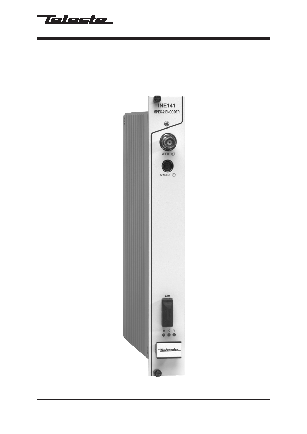
INE1x1 Rack Mount CAT5, Multimode or Singlemode
Encoder Unit with one Video, In-Band Management
General
INE1x1 is a rack mount one channel video Encoder unit for
EASITM surveillance applications (see list of models below).
This unit provides a transparent link of PAL or NTSC video
signal. Transmission is accomplished over an ATM network.
This unit is equipped with an MPEG-2 video compression
engine compliant with the ISO/IEC 13818-2 Standard.
Features
- Selectable CVBS and Y/C video inputs
- GOP structure selectable
- Bit rate scalable up to 18 Mbps
- Frame rate 25 (PAL), 30 (NTSC)
- VP/VC mapping
- Compatibility with DVX-system
- ATM inband control channel
Monitoring Functions
- Video input synchronisation
- ATM frame synchronisation
- Input stream rate
- Output stream rate
Models (Rack mount Cards)
INE101 STM-1/OC-3 Interface CAT5 (100 m)
INE121 STM-1/OC-3 Interface Multimode (2 km)
INE131 STM-1/OC-3 Interface Singlemode Short Haul (15 km)
INE141 STM-1/OC-3 Interface Singlemode Medium Haul (45 km)
INE1x1 Series User Manual rev001 1

INSTALLATION
Quick Instructions
Install the unit into a DVX002-installation frame
equipped with a DVP power supply.
1
The rack must have a unique bus address assigned.
Switch on the system power and see that the “M”, “C”
and “V” -indicators on the front panel of the unit are lit.
2
The “M” (=module) should lit green to show that
hardware is operating properly.
Connect either a CVBS video signal to the BNC
3
connector or a S-VIDEO signal to the mini-DIN
connector of the unit.
Connect the ATM network to port “ATM” in the
4
front panel.
Connect a PC (with the Commander software installed)
to the Control Bus (DVX BUS) using the DVX021
5
connection cable.
Start Commander and select the unit to confi gure and
proceed by fi lling in the required parameters.
Alternatively, if the in-band management is operational
6
over the ATM network, this can be done remotely from a
control center.
Make sure that the unit is not indicating any alarms or
warnings (Status page). The “M”, “C” and “V” -indicators
7
on the front panel should now lit green.
2 INE1x1 Series User Manual rev001
1
Mechanical Installation
INE101
MPEG
ENCODER
2
VIDEO
INE1x1 is installed into a DVX002 installation frame equipped
with a specifi ed DVX bus address (refer to the frame
installation instructions) and a DVP412 (115 V AC) or a
DVP432 (230 V AC) power supply.
The unit can be installed into any frame position, however the
power supply is normally placed in the left-hand side of the
frame. Lock the unit into place using the locking screws on the
front panel (see picture 1).
3
S-VIDEO
Note! See that the “M” (module) -indicator lits green. If the
indicator lits red, the unit in question has a module error and is
giving an alarm. See the “Status page” for more information.
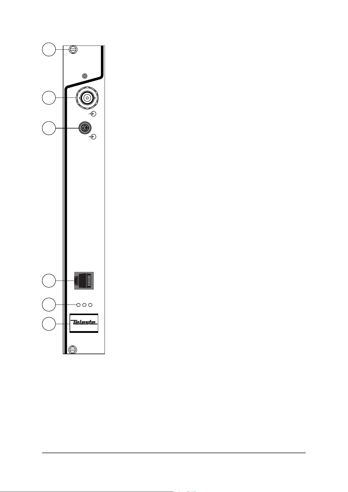
Mechanical Connections
1. Locking screw.
2. Composite video input (BNC male).
3. S-video (Y/C) input (4 pin min-DIN female).
4. STM-1/OC-3 interface, depending on model in
question, either RJ-45 female (when CAT5) or dual SC/PC (when optical).
5. Led indicators, see section below.
6. Handle.
4
ATM
M VC
5
6
Front Panel Leds
When the unit is working properly, the “M” led on the front
panel is green. If the unit senses a module error, the “M” led is
red. Blinking green “M” led indicates that Commander software
is communicating with the unit in question.
When the ATM connection status is OK, the “C” led on the front
panel is green. If the ATM signal is missing or it’s level is too
Picture 1.
INE101 Mpeg-2 Encoder /
connections.
low, the “C” led is yellow.
When the Video connection status is OK, the “V” led on the
front panel is green. If the video signal is missing or it’s level is
too low, the “V” led is yellow.
INE1x1 Series User Manual rev001 3
CONNECTIONS
43
12
General
All products in EASITM family have the same connection scheme
in their connectors. Depending the model in question, there is
video, S-video, audio, data, 10Base-T, ATM and control bus
(DVX bus) connection in the unit.
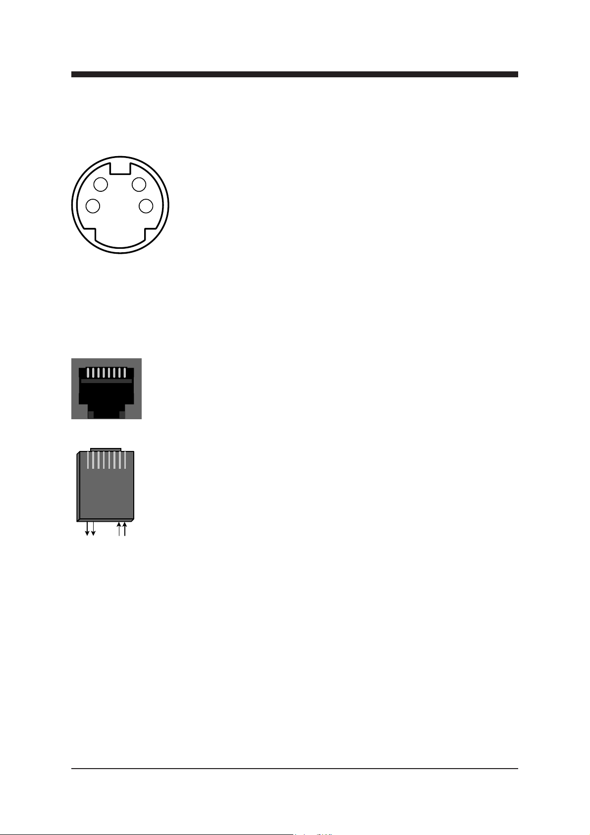
Video Connection
Picture 2.
S-video connector
(4 pin min-DIN female).
Pin 1 - Ground (Y)
Pin 2 - Ground (C)
Pin 3 - Luminance (Y)
Pin 4 - Chrominance (C)
18
AT M
18
Pin 2 - Tx (-)
Pin 7 - Rx (+)
Pin 1 - Tx (+)
Pin 8 - Rx (-)
The video (input) connector in use is either a BNC male
(composite) or a 4 pin min-DIN female (S-video) connector (see
picture 2 and section “Video Page” for detailed description).
ATM Connection
The ATM connector in use is either a RJ-45 female connector
(when CAT5 connection) or dual SC/PC connector (when optical
connection). See picture 3 and section “ATM Page” for detailed
description
Optical ATM connection meets class 1 laser safety requirements
of IEC 825-2: 1993 and US department of health services 21
CFR 1040.10 and 1040.11 (1990) when operated within the
specifi ed temperature, power supply and duty cycle ranges.
Picture 3.
ATM connection (CAT5).
4 INE1x1 Series User Manual rev001

HOW TO CONFIGURE THE INE1x1
MPEG-2 ENCODER
General
This chapter tells how with help of the Commander software you
can confi gure the settings of INE1x1 Encoder and introduce the
functions of the Confi guration Displays. The Confi guration
Displays are a part of the Commander software application.
System Requirements
Hardware requirements
- The PC, minimum requirements: Pentium II prosessor, display
capable to 256 colors and 1024x768 resolution, CD-ROM
drive, 128 MB RAM, Windows 98/Me/NT4.0 (SP 4 upgrade)
/2000 (SP 2 upgrade) /XP.
- DVX021 connection cable between the PC and INE1x1 unit.
Software requirements
- DCS110 Commander software (includes also the
Viewer software).
- DUS100 Viewer Software (the Viewer software
upgrade version). The Viewer Software is a package of DLL
fi les for EASITM products.
The Commander and Viewer softwares
The INE1x1 Encoders are fully controllable with the
Commander Software. The Commander installation package is
supplied on DCS110 CD-ROM. This CD-ROM contains also the
Viewer software.
Software. This CD-ROM is meant for Viewer software upgrade
without need to re-install Commander software.
DUS100 CD-ROM contains only the Viewer
INE1x1 Series User Manual rev001 5

Establishing a Data Connection
1. Connect a DVX021 connection cable between the COM
port of your PC and the Control Bus connector of the
INE1x1 unit.
2. Install the Commander and Viewer softwares by running
autorun.exe (if installation doesn’t start automatically). The
following window appears on the screen (picture 4).
Follow the instructions given during the installation process.
Picture 4.
Commander’s installation setup view (Commander version 2.2).
6 INE1x1 Series User Manual rev001
Starting CATVisorTM Commander
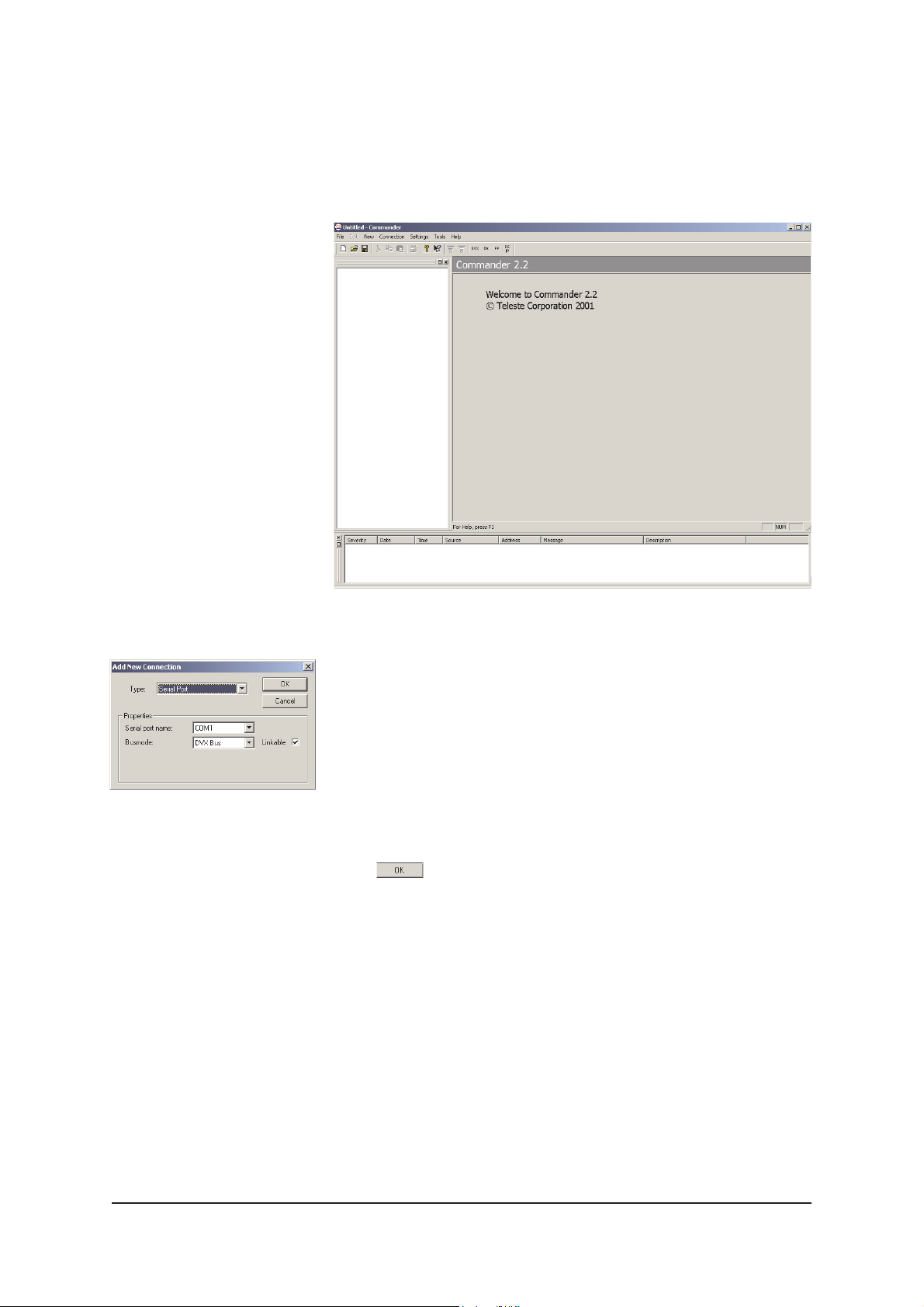
After installing the softwares launch Commander. When the
program has started the following “Untitled Commander”
window appears on the screen (picture 6).
Picture 5.
Commander’s “Add New
Connection” view.
Picture 6.
Commander’s main view.
Commander is now running, but not yet communicating with
INE1x1. Create the connection to the INE1x1 by choosing -->
File/New or Connection/Add New commands from the pulldown menus. The following “Add New Connection” window
appears on the screen (see picture 5).
Make the following settings (these are the default settings):
Type: Serial Port
Serial Port Name: COM1 (choose COM port where the
DVX021 cable is connected, e.g. COM1 port)
Busmode: DVX Bus
Click to continue.
Communication between Commander and INE1x1 is
now created.
Note! You can also re-opened the saved connection by
choosing --> File/Open command from the pull-down menus.
When making a new connection for the fi rst time, you may refer
to the Commander’s User Manual for the correct settings.
INE1x1 Series User Manual rev001 7
 Loading...