

Teleste EASI ATM IND2x2 Series, EASI IND101, EASI IND121, EASI IND141, EASi IND131 User Manual
Page 1
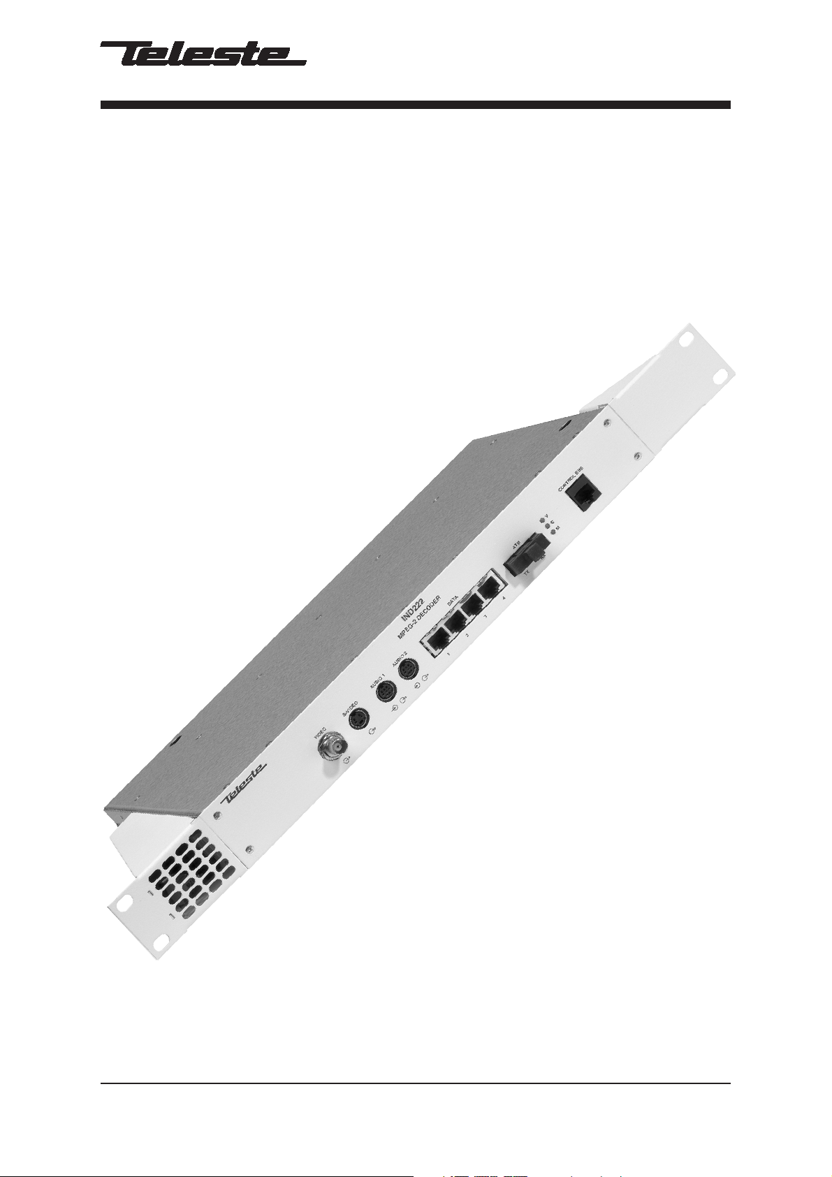
EASITM ATM Series
User Manual
IND2x2 MPEG-2 Decoder
IND2x2 User Manual, 59300041, rev001
Page 2

Contents
Introduction..............................................................................................................1
General.........................................................................................................................................1
Features .......................................................................................................................................1
Monitoring Functions....................................................................................................................1
Models..........................................................................................................................................1
Installation................................................................................................................2
Quick Instructions.........................................................................................................................2
Mechanical Installation.................................................................................................................3
Mechanical Connections ..............................................................................................................3
Front Panel Leds ..........................................................................................................................3
Connections.............................................................................................................4
General.........................................................................................................................................4
S-Video Connection .....................................................................................................................4
Audio Connections .......................................................................................................................4
Data Connections......................................................................................................................4-5
ATM Connection...........................................................................................................................5
Control Bus Connection ...............................................................................................................5
How to Confi gure the IND2x2 MPEG-2 Decoder ...................................................6
General.........................................................................................................................................6
System Requirements..................................................................................................................6
Hardware Requirements .............................................................................................................6
Software Requirements...............................................................................................................6
The Commander and Viewer Softwares.......................................................................................6
Establishing a Data Connection ...................................................................................................7
Starting CATVisorTM Commander.................................................................................................8
CATVisorTM Commander - Connected Window ............................................................................9
Confi guring the Units using CATVisorTM Commander ................................................................10
IND2x2 MPEG-2 Decoder Confi guration Display v1.0 ........................................11
General..................................................................................................................................11-12
Status Page...........................................................................................................................13-14
Properties Page..........................................................................................................................15
ATM Page..............................................................................................................................16-18
Data Page ..................................................................................................................................19
PID Page....................................................................................................................................20
Video Page............................................................................................................................21-22
In-Band Management Page ..................................................................................................23-24
SNMP Page................................................................................................................................25
Constructing EASITM Networks.............................................................................26
Concatenating Encoders and Decoders.....................................................................................26
Data Broadcasting......................................................................................................................26
Copyright Acknowledgements.............................................................................26
Trademark Acknowledgements............................................................................26
IND2x2 Series User Manual rev001
Page 3

INTRODUCTION
IND2x2 Standalone CAT5, Multimode or Singlemode
Decoder Unit with one Video, two Bi-directional Audio
and four Bi-directional Data, In-Band Management
General
IND2x2 is a standalone video & audio Decoder unit for EASITM
surveillance applications (see list of models below). This unit
provides not only a transparent link of PAL or NTSC video
signal, but also two return audio channels and four
independent separately confi gurable general-purpose
asynchronous data channels in both directions. Transmission is
accomplished over an ATM network.
IND2x2 Decoder makes up a pair e.g. with INE1x2 or INE2x2
MPEG Encoder. The transmission is accomplished over ATM
network utilizing AAL5 cell structure.
Features
- Selectable CVBS and Y/C video outputs
- Balanced audio input and output
- Data interface levels compatible with EIA422/485/232
- User data rate up to 57600 bps per channel
- Frame rate 25 (PAL), 30 (NTSC)
- VP/VC mapping
- Compatibility with DVX-system
- ATM inband control channel
Monitoring Functions
- Video input synchronisation
- ATM frame synchronisation
- Input stream rate
- Output stream rate
Models (Standalone units)
IND202 STM-1/OC-3 Interface CAT5 (100 m)
IND222 STM-1/OC-3 Interface Multimode (2 km)
IND232 STM-1/OC-3 Interface Singlemode Short Haul (15 km)
IND242 STM-1/OC-3 Interface Singlemode Medium Haul (45 km)
IND2x2 Series User Manual rev001 1
Page 4

INSTALLATION
Quick Instructions
Install the unit (1U high, 19” wide) to the installation
cabinet. A 12 V supply voltage is provided by a CPS23x
1
mains adapter.
Switch on the system power and see that the “M”, “C”
and “V” -indicators on the front panel of the unit are lit.
2
The “M” (=module) should lit green to show that
hardware is operating properly.
Connect all needed audio/data signals to their
3
respective connectors on the unit’s front panel.
Connect a monitor to either CVBS video output (BNC)
or S-VIDEO output (mini-DIN). These signals are both
4
constantly available.
Connect the ATM network to port “ATM” in the
5
front panel.
Connect a PC (with the Commander software installed)
6
to the Control Bus using the DVX021 connection cable.
Start Commander and select the unit to confi gure and
proceed by fi lling in the required parameters.
Alternatively, if the in-band management is operational
7
over the ATM network, this can be done remotely from a
control center.
Make sure that the unit is not indicating any alarms or
warnings (Status page). The “M”, “C” and “V” -indicators
8
on the front panel should now lit green.
2 IND2x2 Series User Manual rev001
Page 5
Mechanical Installation
IND2x2 is a standalone installation unit. The supply voltage is
provided by a CPS23x mains adapter.
Note! See that the “M” (module) -indicator lits green. If the
indicator lits red, the unit in question has a module error and is
giving an alarm. See the “Status page” for more information.
Mechanical Connections
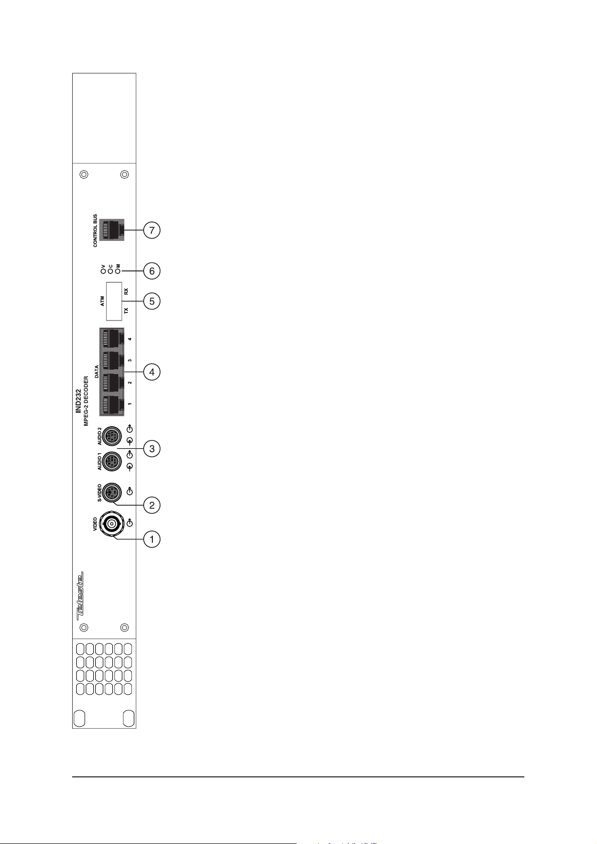
1. Composite video output (BNC male).
2. S-video (Y/C) output (4 pin min-DIN female).
3 .
Audio inputs/outputs (2 channels, 8 pin min-DIN female).
4. EIA-RS data interfaces (4 channels, RJ-45 female).
5. STM-1/OC-3 interface, depending on model in
question, either RJ-45 female (when CAT5) or dual SC/PC (when optical).
6. Led indicators, see section below.
7. Control bus connector (RJ-45 female) for unit’s local
management operation.
Front Panel Leds
When the unit is working properly, the “M” led on the front
panel is green. If the unit senses a module error, the “M” led is
red. Blinking green “M” led indicates that Commander software
is communicating with the unit in question.
When the ATM connection status is OK, the “C” led on the front
panel is green. If the ATM signal is missing or it’s level is too
low, the “C” led is yellow.
When the Video connection status is OK, the “V” led on the
front panel is green. If the video signal is missing or it’s level is
too low, the “V” led is yellow.
Picture 1.
IND232 Mpeg-2 Decoder /
connections.
IND2x2 Series User Manual rev001 3
Page 6
CONNECTIONS
43
12
General
All products in EASITM family have the same connection scheme
in their connectors. Depending the model in question, there is
video, S-video, audio, data, 10Base-T, ATM and control bus
(DVX) connection in the unit.
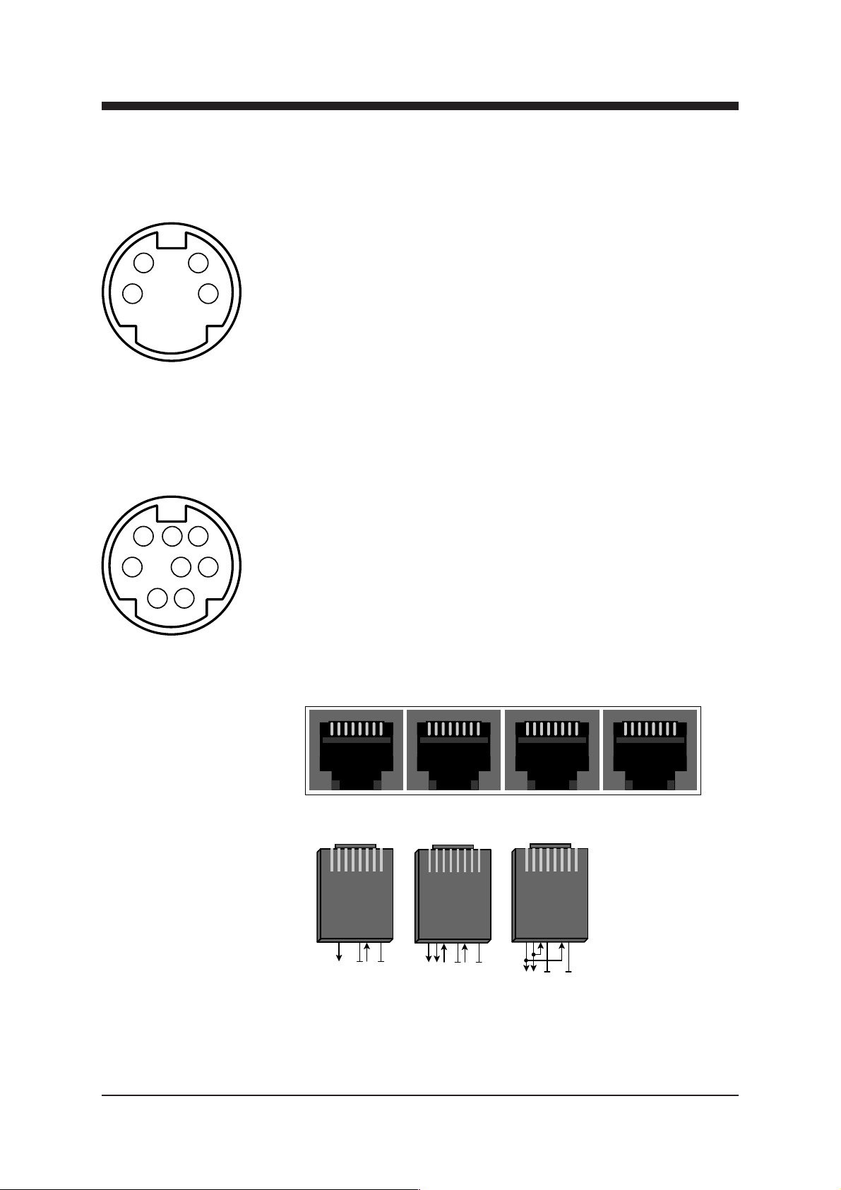
Video Connection
Picture 2.
S-video connector
(4 pin min-DIN female).
Pin 1 - Ground (Y)
Pin 2 - Ground (C)
Pin 3 - Luminance (Y)
Pin 4 - Chrominance (C)
876
345
1
2
Picture 3.
Audio connector
(8 pin min-DIN female).
Unbalancced connection:
Pin 1 - Ground (input)
Pin 2 - Ground (output)
Pin 3 - Audio input
Pin 5 - Audio output
The video (output) connector in use is either a BNC male
(composite) or a 4 pin min-DIN female (S-video) connector (see
picture 2 and section “Video Page” for detailed description).
Audio Connections
The audio connectors (1 & 2) contains one bi-directional audio
channel line. The audio impedance is constant and cannot be
adjusted. The audio input impedance is >10 kΩ and the output
impedance is <10 Ω. The connector in use is a 8 pin min-DIN
female connector (see picture 3 for detailed description).
Data Connections
The data connectors (1...4) contains one bi-directional data
channel. The connector in use is a RJ-45 female connector (see
pictures 4 and section “Data Page” for detailed description).
1891617242532
DATA
Balancced connection:
Pin 1 - Shield
Pin 2 - Shield
Pin 3 - Audio input (+)
Pin 5 - Audio output (+)
Pin 6 - Audio input (-)
Pin 8 - Audio output (-)
12 34
18
User
RS232
Full-Duplex
Pin 2 - Tx
Pin 5 - Ground
Pin 6 - Rx
Pin 8 - Ground
18
User
RS422/485
Full-Duplex
Pin 2 - Tx (-)
Pin 5 - Ground
Pin 6 - Rx (+)
Pin 8 - Ground
Pin 3 - Rx (-)
Pin 1 - Tx (+)
18
User
RS485
Half-Duplex
Pin 1 & 6 - Tx / Rx (+)
Pin 2 & 3 - Tx / Rx (-)
Pin 5 - Ground
Pin 8 - Ground
Picture 4.
Data options / connections.
4 IND2x2 Series User Manual rev001
Page 7
AT M
18
18
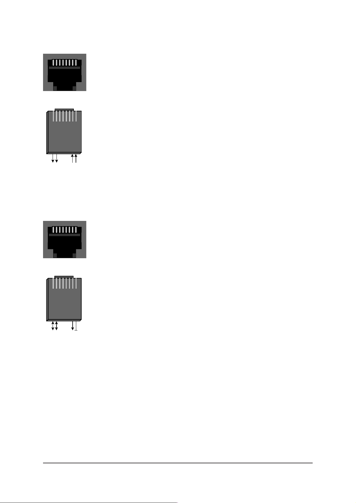
Pin 2 - Tx (-)
Pin 7 - Rx (+)
Pin 1 - Tx (+)
Pin 8 - Rx (-)
Picture 5.
ATM connection (CAT5).
CONTROL BUS
18
ATM Connection
The ATM connector in use is either a RJ-45 female connector
(when CAT5 connection, see picture 5) or dual-SC/PC connector
(when optical connection).
See section “ATM Pag e” for detailed description.
Optical ATM connection meets class 1 laser safety requirements
of IEC 825-2: 1993 and US department of health services 21
CFR 1040.10 and 1040.11 (1990) when operated within the
specifi ed temperature, power supply and duty cycle ranges.
Control Bus (DVX BUS) Connection
The Control Bus (DVX BUS) connector in use is a RJ-45
female connector (see picture 6 for detailed description).
The Control Bus connection is meant to create communication
between INE2x2 unit and Commander software.
18
Control Bus
(DVX BUS)
Pin 2 - RS485 (-)
Pin 1 - RS485 (+)
Pin 8 - Ground
Pin 7 - Vout (+12V)
Picture 6.
Control bus connection.
IND2x2 Series User Manual rev001 5
Page 8

HOW TO CONFIGURE THE IND2x2
MPEG-2 DECODER
General
This chapter tells how with help of the Commander software you
can confi gure the settings of IND2x2 Decoder and introduce the
functions of the Confi guration Displays. The Confi guration
Displays are a part of the Commander software application.
System Requirements
Hardware requirements
- The PC, minimum requirements: Pentium II prosessor, display
capable to 256 colors and 1024x768 resolution, CD-ROM
drive, 128 MB RAM, Windows 98/Me/NT4.0 (SP 4 upgrade)
/2000 (SP 2 upgrade) /XP.
- DVX021 connection cable between the PC and IND2x2 unit.
Software requirements
- DCS110 Commander software (includes also the
Viewer software).
- DUS100 Viewer Software (the Viewer software
upgrade version). The Viewer Software is a package of DLL
fi les for EASITM products.
The Commander and Viewer softwares
The IND2x2 Decoders are fully controllable with the
Commander Software. The Commander installation package is
supplied on DCS110 CD-ROM. This CD-ROM contains also the
Viewer software.
Software. This CD-ROM is meant for Viewer software upgrade
without need to re-install Commander software.
DUS100 CD-ROM contains only the Viewer
6 IND2x2 Series User Manual rev001
Page 9
Establishing a Data Connection
1. Connect a DVX021 connection cable between the COM
port of your PC and the Control Bus connector of the
IND2x2 unit.
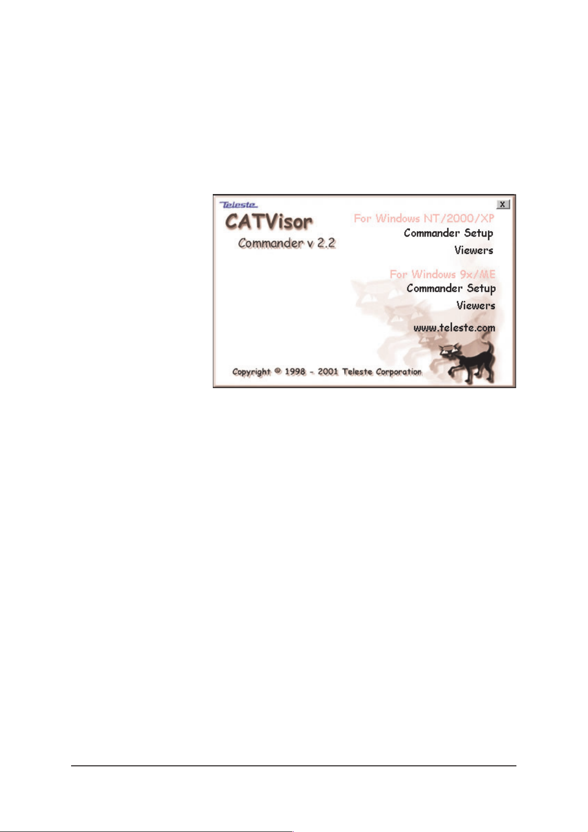
2. Install the Commander and Viewer softwares by running
autorun.exe (if installation doesn’t start automatically). The
following window appears on the screen (picture 6).
Follow the instructions given during the installation process.
Picture 7.
Commander’s installation setup view (Commander version 2.2).
IND2x2 Series User Manual rev001 7
Page 10
Starting CATVisorTM Commander
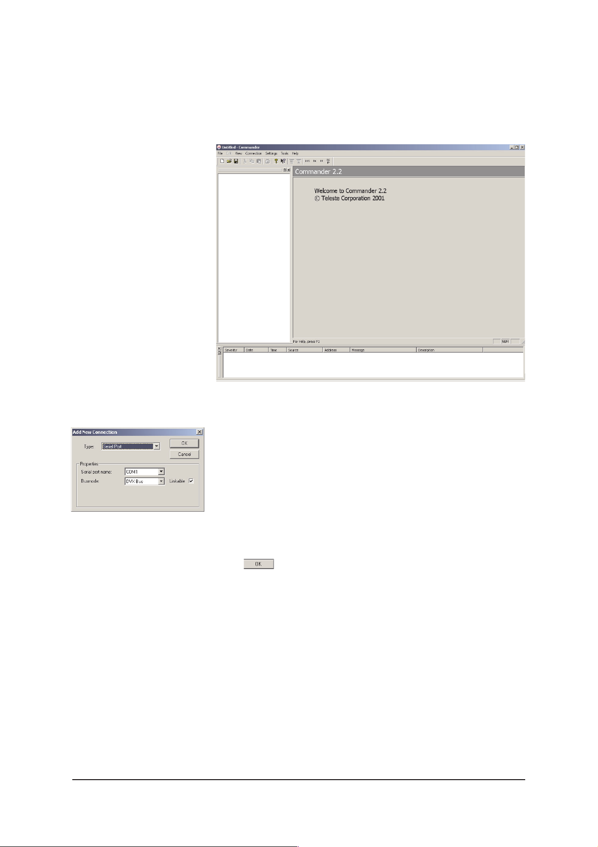
After installing the softwares launch Commander. When the
program has started the following “Untitled Commander”
window appears on the screen (picture 9).
Picture 8.
Commander’s “Add New
Connection” view.
Picture 9.
Commander’s main view.
Commander is now running, but not yet communicating with
IND2x2. Create the connection to the IND2x2 by choosing -->
File/New or Connection/Add New commands from the pulldown menus. The following “Add New Connection” window
appears on the screen (see picture 8).
Make the following settings (these are the default settings):
Type: Serial Port
Serial Port Name: COM1 (choose COM port where the
DVX021 cable is connected, e.g. COM1 port)
Busmode: DVX Bus
Click to continue.
Communication between Commander and IND2x2 is
now created.
Note! You can also re-opened the saved connection by
choosing --> File/Open command from the pull-down menus.
When making a new connection for the fi rst time, you may refer
to the Commander’s User Manual for the correct settings.
8 IND2x2 Series User Manual rev001
Page 11
Pull-Down menus
CATVisorTM Commander - Connected Window
Toolbar
Element Tree Directory
Element Tree Window
Event Window
Element Window
Status Bar
Picture 10.
Commander Main View, connected window.
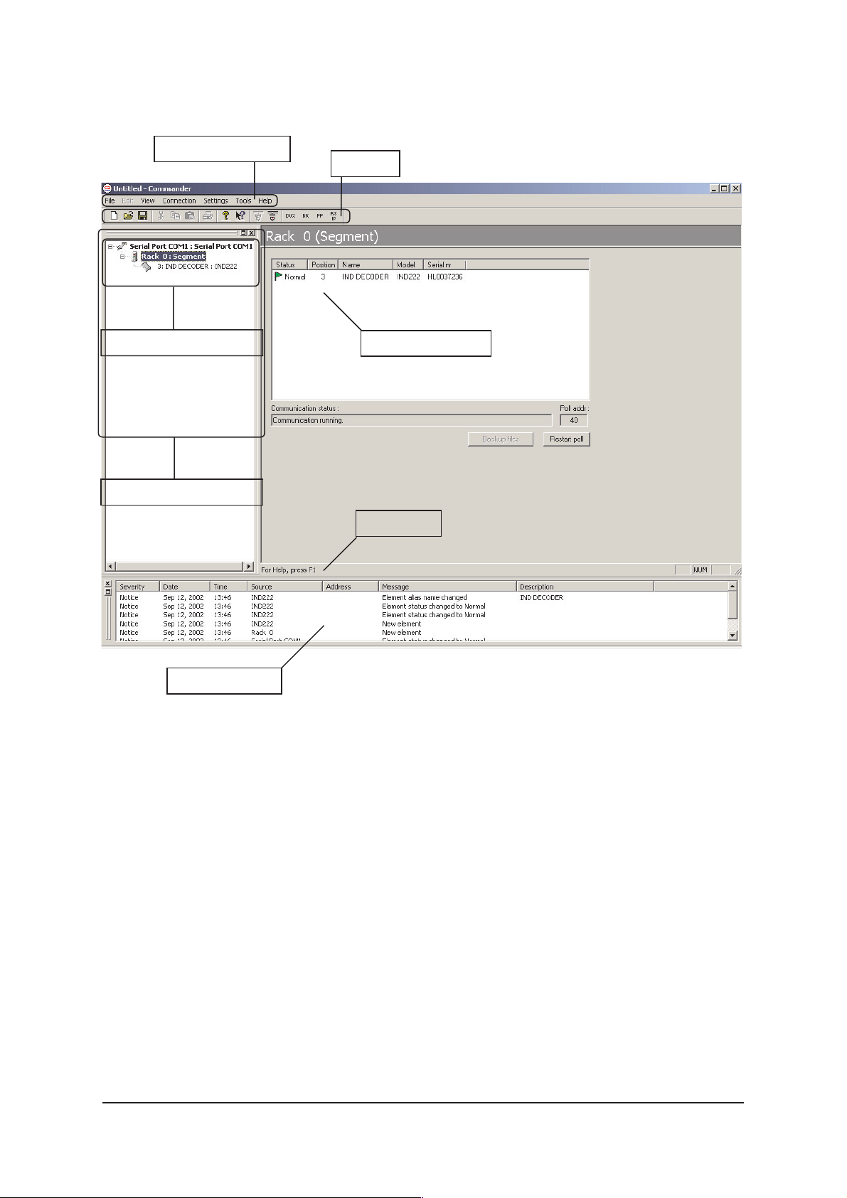
The Commander main view consist of the Element Tree
Window, Element Window, Event Window, Pull Down
Menus, the Tool Bar and the Status Bar.
The Commander main view window is divided into three main
sections: Element Tree Window, Element Window and Event
Window (see picture 10).
When a connection is created, the connected unit found
appears in the Commander’s Element Tree Window / Element
Tree Directory and it is also listed in the Event Window.
The Event Window displays all detected events in connection.
The Element Window displays more detailed information on
an individual unit selected in the Element Tree Window.
IND2x2 Series User Manual rev001 9
Page 12
Confi guring the unit using CATVisorTM Commander
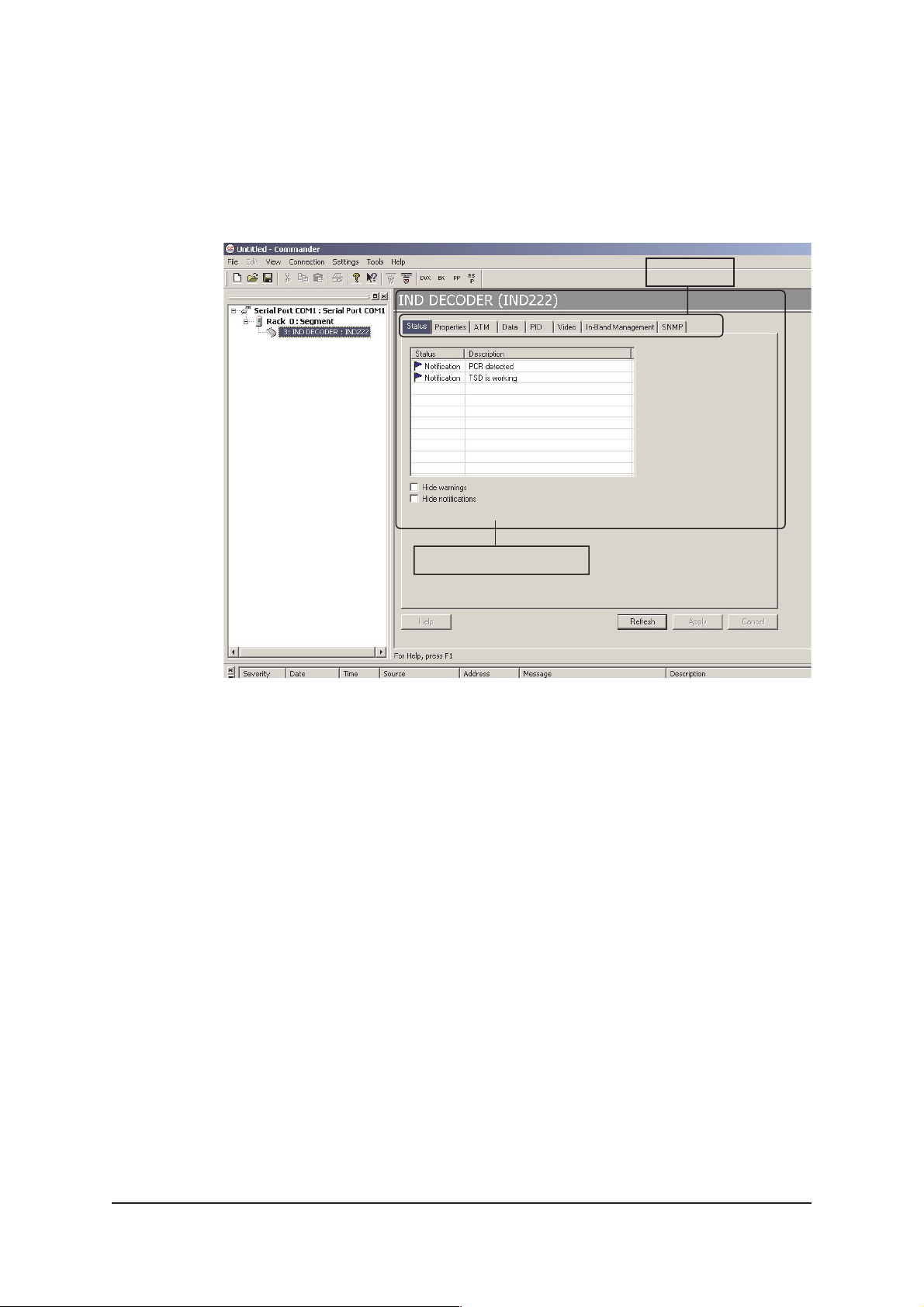
Clicking on a specifi c unit in the Element Tree Directory, a
Confi guration Display appears on the right side. The
Confi guration Display includes all the programmable and
monitorable controls and settings of that unit.
Headings
Confi guration Display
Picture 11.
The Confi guration Display.
The Confi guration Display window consists of several pages;
Status, Properties, ATM, Data, PID, Video, In-Band
Management and SNMP. Only one page is completely visible
at one time. You can activate a page simply by clicking the
page’s heading.
See section “IND2x2 MPEG-2 Decoder CONFIGURATION
DISPLAY V1.0” for more details (page 11).
Note! If there is no information (e.g. no all headings) visible
on Confi guration Display although an element has been
chosen from the Element Tree Directory, the viewer DLL fi le
has failed to load properly. Then either the DLL fi le is
missing or not updated. Please check the software version
and if needed, update the Viewer software with the latest
version of DUS100.
10 IND2x2 Series User Manual rev001
Page 13
IND2x2 MPEG-2 DECODER CONFIGURATION
DISPLAY V1.0
General
Commander’s Confi guration Display window consists of
several pages. Only one page is completely visible at one time.
You can activate a page simply by clicking the page’s heading
(see pictures 11 and 12).
Picture 12.
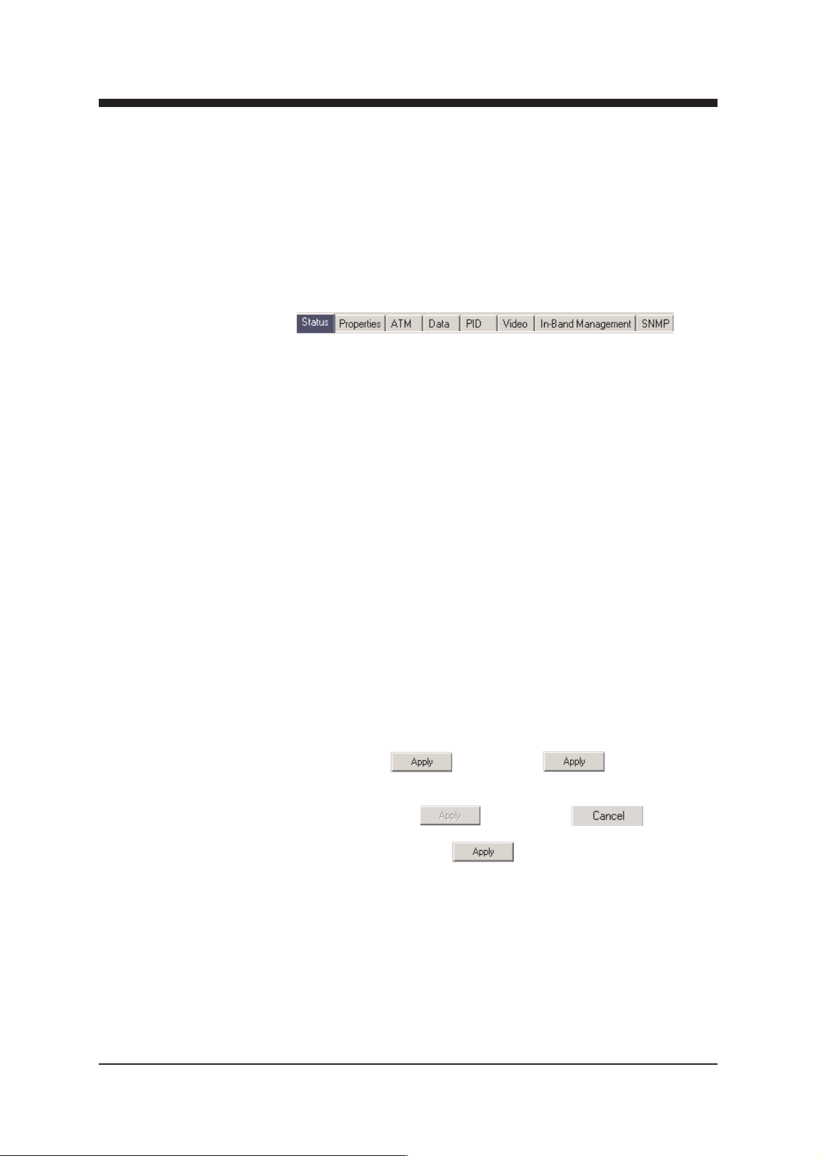
Commander’s Confi guration Display page’s headings.
IND2x2 Decoder (IND) has the following confi guration display
pages that are introduced in this document:
- Status
- Properties
- ATM
- Data
- PID
- Video
- In-Band Management
- SNMP
The information on confi guration sheets is shown in data fi elds
or boxes. You can change settings in data fi elds or boxes
whose background is white. Place your cursor in the desired
data fi eld or box and enter the new setting. Some settings are
entered by ticking a checkbox or clicking on a radio button, by
selecting from a pull-down list or by scrolling digits with the
help of spin buttons.
When you have entered a new setting, the Apply button is
activated --> “ “. By clicking Apply you verify the
new settings and they will be sent to the unit. If these settings
are legal, they become valid immediately and the Apply button
turns inactive --> “ “. By clicking Cancel you can
restore the original settings. Note that you can change several
settings before clicking Apply . If you entered settings with
the help of spin buttons, the Apply command is not needed.
IND2x2 Series User Manual rev001 11
Page 14

If a data fi eld or box has a grey background, it contains readonly information that cannot be edited. Red, yellow and green
backgrounds of data fi elds or boxes indicate alarms, warnings
and notifi cations related to the settings or values in them.
The new settings are saved in the non-volatile memory of the
confi gured unit. In this way they will be maintained even if the
power is lost temporarily.
When you have fi nished editing, check that the confi gured units
are not indicating any warnings or alarms. For more information
about alarms and warnings, please see the “Status Page”.
For more detailed instructions about how to use CATVisorTM
Commander, please refer to its User Manual.
Note! All changes in settings must be confi rmed in each
page by pressing Apply .
12 IND2x2 Series User Manual rev001
Page 15
Status Page
Picture 13.
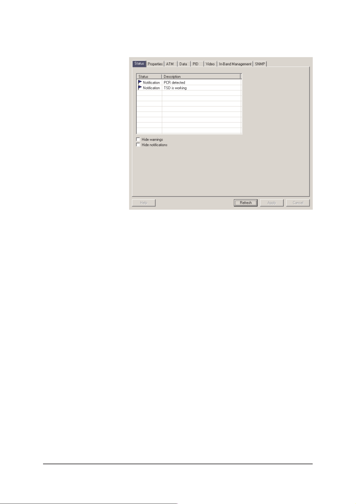
Commander’s “Status” page view.
The Status Page lists information messages about the
TM
Decoder’s present status. The EASI
Confi gurer divides these
messages into three different categories according to severity
and uses Status Flags to make them more noticeable:
- Alarm messages are indicated with red fl ag.
- Warning messages are indicated with yellow fl ag.
- Notifi cations are indicated with green fl ag.
Status Flags and the corresponding text labels appears in the
Status fi eld. A short description of the event can be read in the
Description fi eld. You can also hide warnings and/or
notifi cations by ticking the corresponding checkboxes. Alarms
cannot be hidden. The “Apply” command is not needed to
verify these commands.
IND2x2 Series User Manual rev001 13
Page 16

Messages are divided into four groups:
- Alarms concerning BIOS.
- Alarms concerning application.
- Warnings concerning application.
- Notifi cations concerning application.
Alarm
In case the unit senses an alarm a red Alarm fl ag appears in
the Commander’s Element Directory Window. The
description of this alarm can be read from the Commander’s
Status Page. At the same time a green “M” led indicator in the
unit’s front panel turns to yellow.
Warning
Usually a yellow Warning fl ag in the Commander’s Element
Directory Window indicates that there is something wrong
with the confi guration.
Notifi cation
A Notifi cation fl ags in the Commander’s Status Page indicates
informative value only.
14 IND2x2 Series User Manual rev001
Page 17
Properties Page
Picture 14.
Commander’s “Properties” page view.
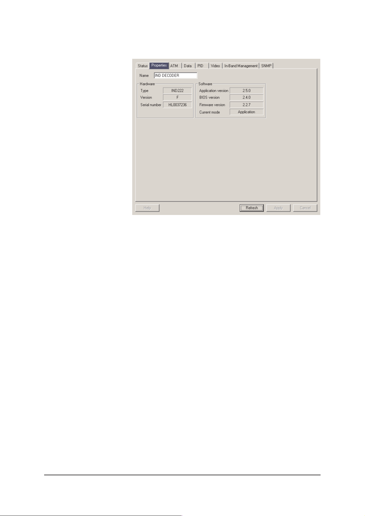
The Properties page displays information of the unit’s
hardware and software.The unit’s name which you can see on
the Element Tree Window and Element Window can be set
on this page.
IND2x2 Series User Manual rev001 15
Page 18
ATM Page
Picture 15.
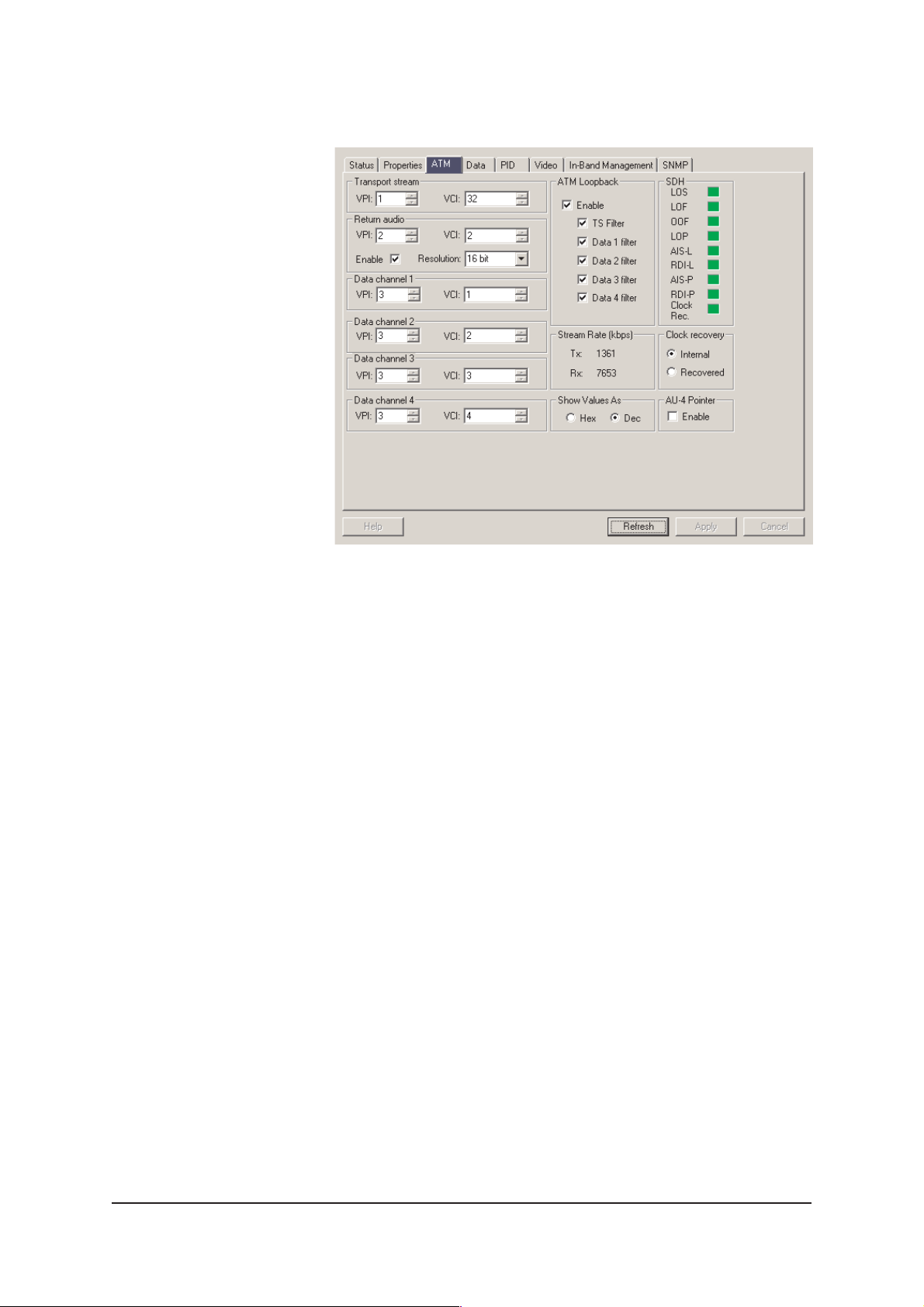
Commander’s “ATM” page view.
The ATM page displays ATM/SDH (Asychronous Transfer
Mode / Synchronous Digital Hierarchy) connection status and
allows you to set all necessary VPI’s and VCI’s. VPI is the
Virtual Path Identifi er. VCI is the Virtual Channel Identifi er. VPI
is selectable between 1…255 and VCI between 1…65500.
These values compose a pair and it is not allowed to have two
similar identifi er pairs for different streams in one network.
Transport stream frame
In this frame you can set the received video & audio signals.
Transport stream is the MPEG-2 compressed bitstream that
consists of video & audio.
Return audio frame
This is the dual audio channel digitized and sent by Decoder
(not compressed, sampling frequency 35.2 Mhz). You can
enable the return channel by ticking the appropriate checkbox.
Resolution window is used to minimize the required audio
bandwidth over ATM network. Normal setting is 16 bit with
around 1.1 Mbps bandwidth. Selecting 14 bit reduces the ATM
bandwidth around 200 kbit/s.
Data channel frames 1…4
The four RS data channels are all individual and can be routed
independently through the ATM network.
16 IND2x2 Series User Manual rev001
Page 19

Loopback enable checkbox
When this box is ticked all incoming ATM cells are forwarded to
the next device in the network. Even those cells received by
the Decoder itself are copied forward. This allows Decoder
daisy-chaining and full utilisation of STM-1 capacity.
TS Filter checkbox
Because of the ability to loop forward the ATM stream it is
possible that the cells once sent are returning back to the
transmitting unit. In order to prevent those cells to start another
round in the network they are discarded. This box is a reminder
of the automatic cell deleting that takes place in every
Decoder. This feature is not user controllable.
Data Filter checkboxes
When theses boxes are ticked the bidirectional data channels
are not forwarded at the ATM level. If this box is clear the data
channels are considered to be broadcast type and they are not
only picked up by this unit but also are passed forward to the
next device in the ATM network. When using data broadcasting
and there are more than one terminal unit connected please
note that only one of them is allowed to answer at a time.
Multiple answers will cause a confl ict at the master device of
the RS data network.
Stream Rate frame
This frame indicates the transmitted and received ATM bitrate
in kbps.
AU-4 Pointer checkbox
For SDH network operation the AU-4 pointer can be enabled or
disabled. The default setting is disabled (Sonet operation).
SDH frame
This frame displays the following fl ags:
LOS = Loss of Signal
The LOS alarm indicates that there are no transitions occurring
in the signal received by the network element.
LOF = Loss of Frame
The receiver raises the LOF alarm when an OOF condition
persists for 3 ms or longer. It clears the alarm when it receives
a valid signal for 3 ms.
IND2x2 Series User Manual rev001 17
Page 20

OOF = Out of Frame
An OOF alarm occurs when one or more bit errors in each
framing pattern are detected for four consecutive frames.
LOP = Loss of Pointer
A network element transmits a LOP alarm downstream when it
receives 8 consecutive frames containing an invalid pointer, or
8 consecutive New Data Flags (NDF’s other than in a
concatenation indicator ).
AIS-L = Alarm Indication Signal-Line
RDI-L = Remote Defect Indicator-Line
AIS-P = Alarm Indication Signal-Path
RDI-P = Remote Defect Indicator-Path
Alarm Indication Signals and Remote Defect Indicators are
mechanisms used to report network faults.
Clock Rec.
This fl ag indicates if the clock recovered from the incoming
stream is close enough to the frequency of the reference
oscillator.
All changes in settings should be confi rmed by
pressing Apply .
18 IND2x2 Series User Manual rev001
Page 21
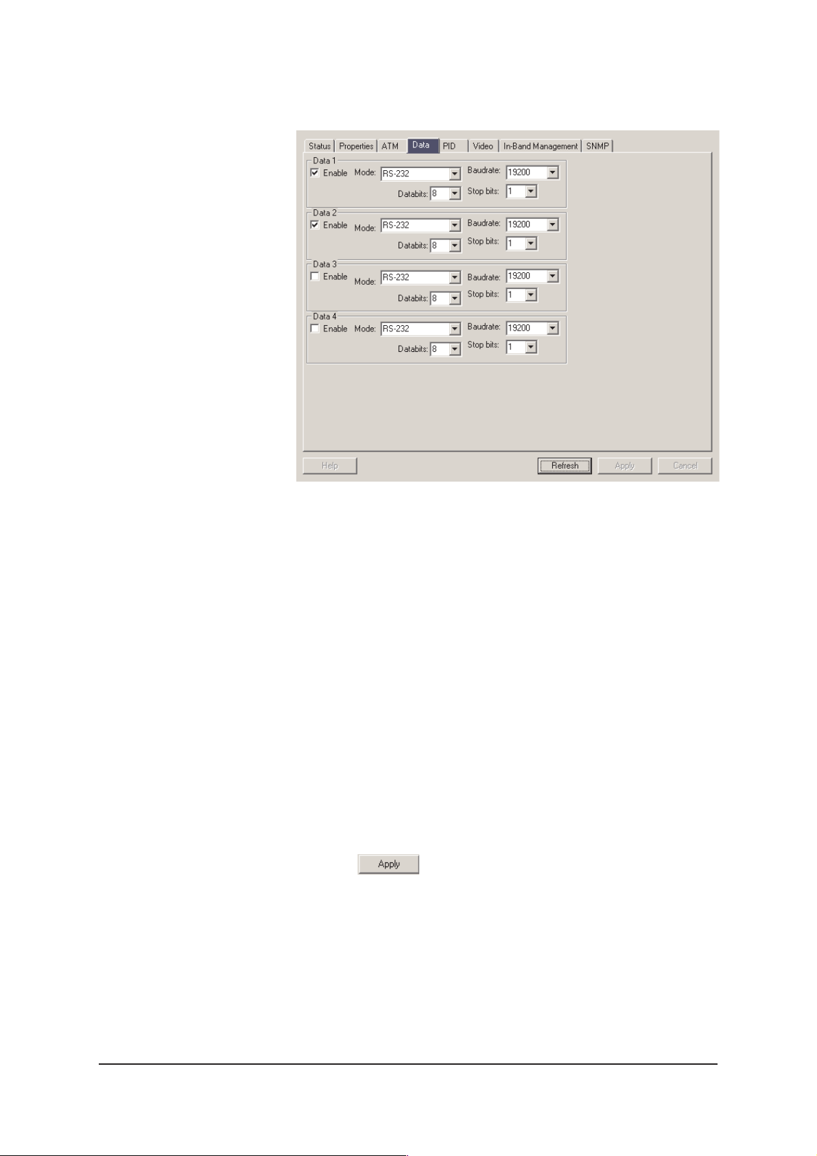
Data Page
Picture 16.
Commander’s “Data” page view.
The Data page is used to enable and confi gure all four
supported RS data channels individually. In order to operate
over ATM each data channel must have similar confi guration at
both ends. The VP/VC settings for all of these channels are
located on the ATM page.
Data Channel frames 1…4
User selectable RS modes are RS232, RS422, RS485 half
duplex and RS485 full duplex (4-wire). For correct wiring refer
to attachment A. User selectable baudrates for each channel
are 2400, 4800, 9600, 14400, 19200, 38400 and 57600.
Alternatives for number of databits is 8 and 9. Alternatives for
number of stopbits is 1 and 2. If the channel is not in use, it
should be disabled. This can be done by removing the tick from
the Enable checkbox.
All changes in settings should be confi rmed by
pressing Apply .
IND2x2 Series User Manual rev001 19
Page 22
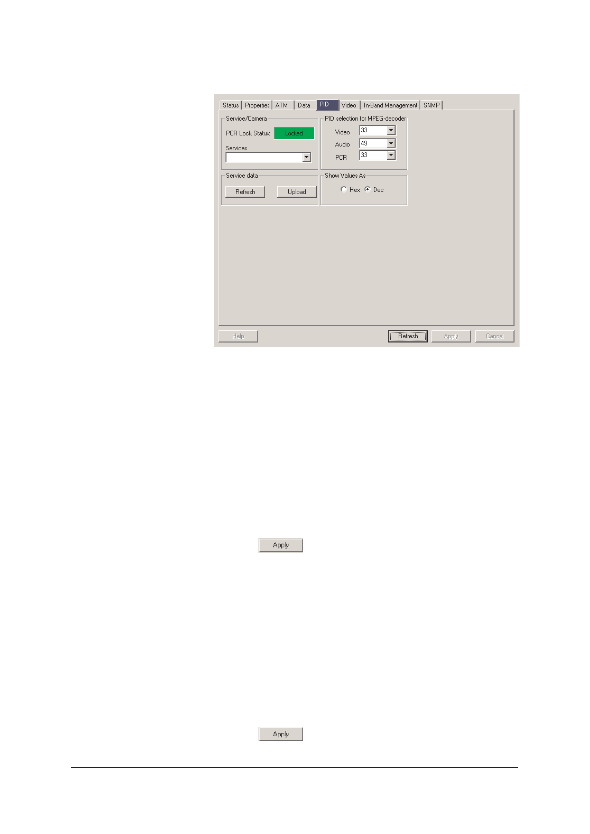
PID Page
Picture 17.
Commander’s “PID” page view.
The PID page is used for confi guring MPEG reception. In
MPEG compression PID is Program IDentifi er and PCR stands
for Program Clock Recovery. PID is an individual identifi er for
separate MPEG data streams. PCR PID indicates the stream
where the syncronisation information is included.
Service/Camera frame
PCR Lock Status indicates when the Decoder has tuned to a
valid stream and synchronisation is achieved.
Services window shows a list of all programs available. Tuning
to a certain channel in the list can be done by choosing it and
pressing Apply .
Service data
Refresh button - not yet defi ned
Upload button - not yet defi ned
PID selection frame
PID selection is usually a half-automatic function. When there
is a valid stream detected all PIDs can be set by selecting P0
from the Services menu. You can also set PIDs manually
between 1…255.
All changes in settings should be confi rmed by
pressing Apply .
20 IND2x2 Series User Manual rev001
Page 23
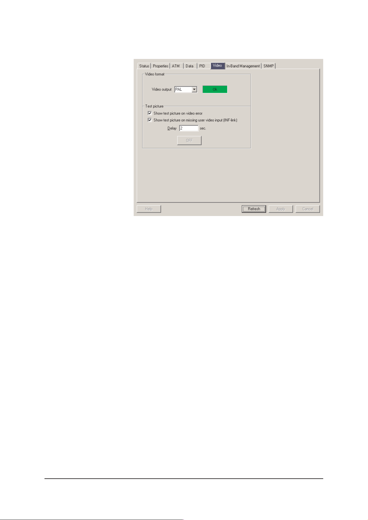
Video Page
Picture 18.
Commander’s “Video” page view.
On the Video Page you can confi gure the physical
monitor interface.
Video Format
EASITM Decoders support PA L and NTSC video standards.
This setting should match with the video connected to the input
of the EASITM Encoder.
Test Picture
In case of a lost signal the Decoder keeps repeating the last
picture. On the screen it means a still picture. The still picture
can be avoided by ticking the checkbox “Show test picture on
error”. This setting allows the Decoder to switch on the test
picture automatically after a certain period.
Delay window presents the time the Decoder waits before it
turns on the test picture after signal synchronisation is lost. The
time is settable between 1…600 s and the recommended value
is below 10 seconds.
ON/OFF button
This button allows you to turn on/off the test picture manually.
This feature can be used to check and set the monitor
confi guration even if there is no received video signal. It is not
allowed to turn off the test picture if there is not a valid signal.
IND2x2 Series User Manual rev001 21
Page 24

Video Signal - indicator
Text “OK” on a green background indicates that the Video
Format and Video Source are set correctly and that the
Decoder receives a correct video signal. Text “FAILED” on a red
background indicates a failure in video reception. In this case
check the video source and all connections and match the
above “Source” & “Format” selections according to the
incoming video.
Also the Decoder front panel led marked “V” indicates the status
of the video signal. Green indicates “OK” and yellow for failure.
All changes in settings should be confi rmed by
pressing Apply .
22 IND2x2 Series User Manual rev001
Page 25
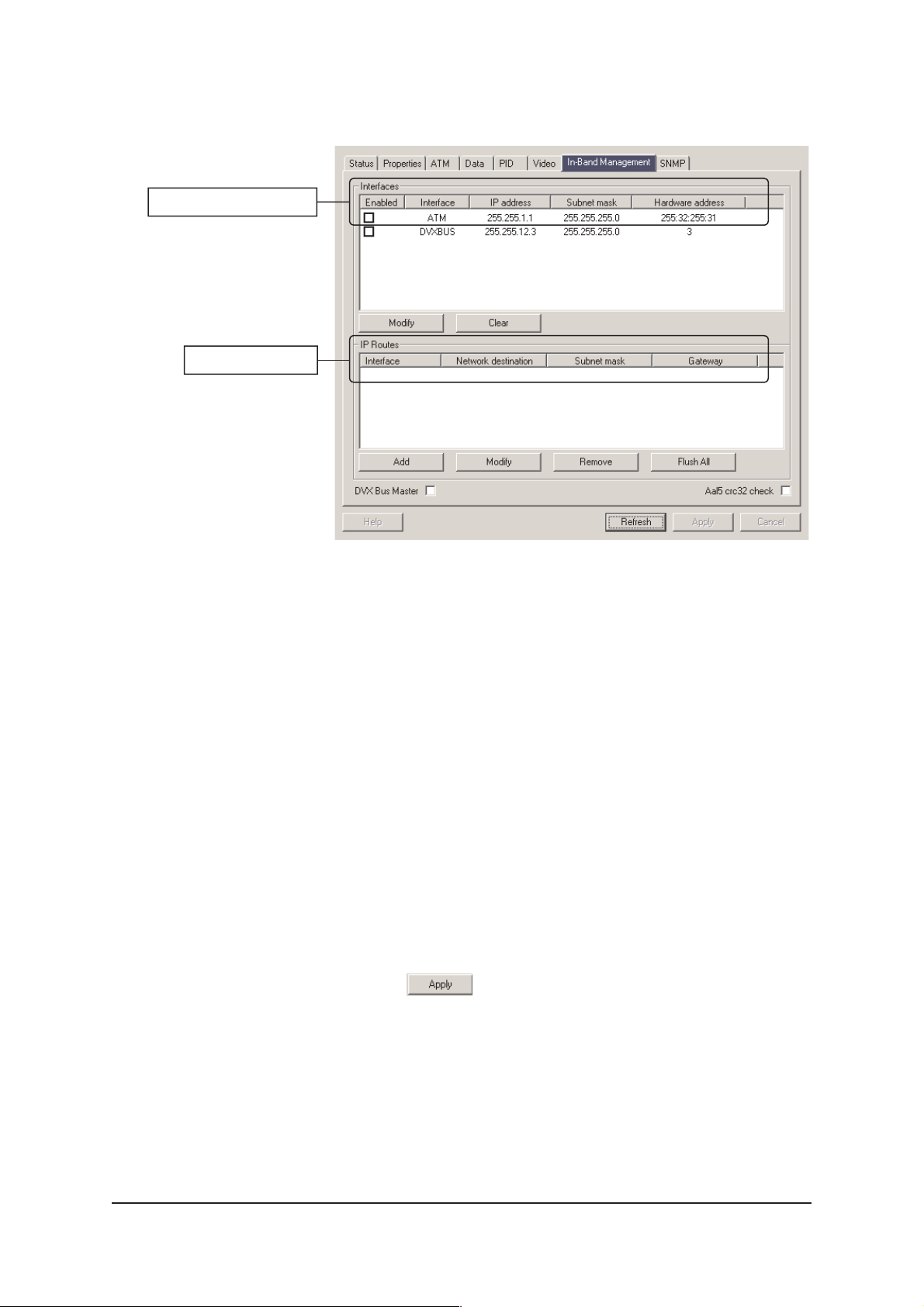
ATM Interface settings
IP Route settings
In-Band Management Page
Picture 19.
Commander’s “In-Band Management” page view.
EASITM Decoder confi guration pages are accessible also over
the ATM network by utilising In-Band Management. This
feature allows the user to confi gure all Encoders and Decoders
in the network from one location. Locally you connect to the
DVX bus but in remote location the connection is established
either with an ATM network interface card or via EASITM ATM
Node Ethernet connection.
The only addressable port is the ATM port. This is the address
of the Decoder and it has to be unique in the whole network.
When you set or change this address make sure that the
address does not exist somewhere else in the network.
There are two confi gurable VPI/VCI pairs for the In-Band
Management data. The Decoder listens to both of these pairs
set in this window. They allow to confi gure each Decoder to be
part of two different management groups.
All changes in settings should be confi rmed by
pressing Apply .
IND2x2 Series User Manual rev001 23
Page 26
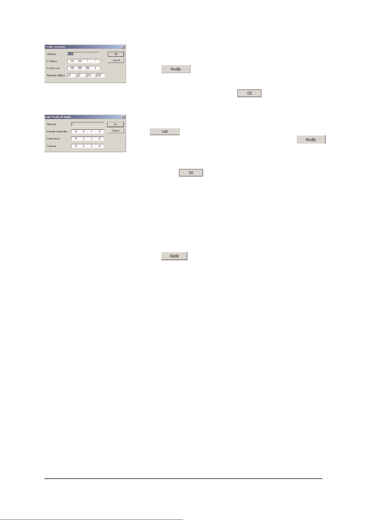
Picture 20.
Commander’s “Modify (ATM)
Interface” view.
Picture 21.
Commander’s “Add/Modify IP
Route” view.
How to modify ATM Interface
Select the ATM interface from the Interface list (see picture 19
and click modify to modify ATM interface. The following
“Modify Interface” window appears on the screen (see picture
20). Set required values to IP address, Subnet mask and
hardware address fi elds and click OK to continue. Enable
the ATM interface by ticking the checkbox “Enabled”.
How to add/modify IP Route
Click Add to add new IP Route or select the IP Route
from the IP Routes Interface list (see picture 19). Click modify
to modify IP Route. The following “Add/Modify IP Route”
window appears on the screen (see picture 21). Set required
values to Network Destination, Subnet mask and Gateway
fi elds and click OK to continue.
DVX Busmaster checkbox
Not used.
Aal5 crc32 check checkbox
ATM checksum calculation, normally not used.
All changes in settings should be confi rmed by
pressing Apply .
24 IND2x2 Series User Manual rev001
Page 27
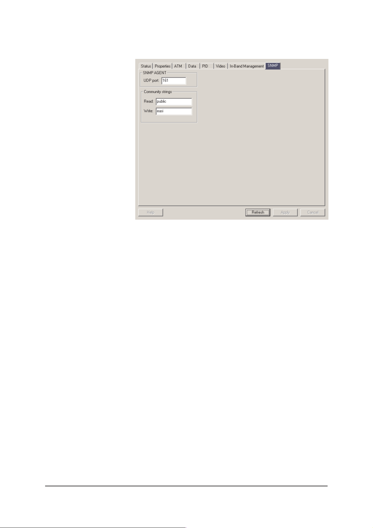
SNMP Page
Picture 22.
Commander’s “SNMP” page view.
The SNMP page is not used in normal operation
(for factory use only).
25 IND2x2 Series User Manual rev001
Page 28

CONSTRUCTING EASITM NETWORKS
Concatenating Encoders and
Decoders
Concatenating is used to fully utilise the STM-1 capacity. The
ATM bitrate output from one Encoder can vary between 3,4
Mbps…18 Mbps, which leaves available capacity for other
services when inserted into 155 Mbps STM-1 data stream.
This gap can be fi lled by daisy-chaining several Encoders in
the same ATM loop.
Recommendations for concatenating is max. twenty (20)
devices (Encoders, Decoders or mixture of both) per one
STM-1/OC-3 loop. The maximum calculated bitrate for all
services (note also all return audio and data channels)
together should not exceed 120 Mbps in one loop.
Data broadcasting
Data broadcasting can be used in special applications.
Copyright Acknowledgements
Information in this document is subject to change without notice and does not represent a
commitment on the part of Teleste Corporation. The software as described in this document
is supplied only under a licence agreement. The software may be used or copied only in
accordance with the terms of the agreement.
Copyright © Teleste Corporation. All Rights Reserved.
No part of this document may be reproduced, transmitted, stored in a retrieval system, or
translated into any other language without the express permission of Teleste Corporation.
Teleste Corporation
Video Networks
P.O. Box 323
FIN-20101 Turku
FINLAND
www.teleste.com/cctv
Trademark Acknowledgements
EASITM and CATVisor™ Commander are trademarks of Teleste Corporation.
IND2x2 Series User Manual rev001 26
 Loading...