

Teleste E3 User Manual
User Manual E3
59300623 Rev.001
5.4.2018 1(20)
E Series
User Manual
Teleste Corporati on
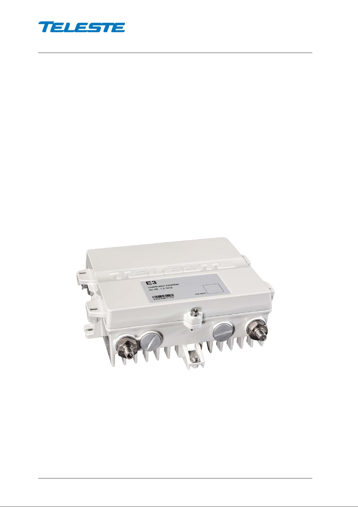
E3 Compact amplifier

User Manual E3
59300623 Rev.001
5.4.2018 2(20)
Contents
Introduction ........................................................................................................ 2
Installation .......................................................................................................... 3
Mounting .............................................................................................................. 3
Interfaces ............................................................................................................. 4
Coaxial connections............................................................................................. 5
Powering ............................................................................................................. 6
Front panel ......................................................................................................... 7
Features .............................................................................................................. 8
Diplex and output modules .................................................................................. 8
Forward path ........................................................................................................ 9
Return path ........................................................................................................ 10
Alarms ............................................................................................................... 11
Local user interface ......................................................................................... 12
Introduction
E61 RIS receiver with USB .............................................................................. 14
Installation .......................................................................................................... 14
Establishing connection ..................................................................................... 15
Software update ................................................................................................. 16
Viewer pages ..................................................................................................... 17
Legal declarations ........................................................................................... 20
E3 is a compact dual output amplifier with wide 16…42 dB gain adjustment
range making it suitable for both distribution purposes and line extender use.
The E3 amplifier sup ports 1.2 GH z frequenc y range which ensures fulfilm ent of
all future bandwidth nee ds. The upstream signal path is flexible an d it can be
updated to 204 MHz.
Adjustments use e lectrical controls t hus elim inating the need of the usual plugin attenuators in the system set-up. Other standard features include reliable
power supply, built-in return path amplifier as well as an efficient surge and ESD
protection.
Ingress switches can be remotely controlled via FSK communication of an
optional E61 RIS receiver. This one way com munication channel also en ables
remote update of software.
Local configuration of E3 is done via its built-in display and pushbutton user
interface. E61 module can be us ed to add USB in terface f or c onfiguratio n using
a Windows PC or tablet equipped with CATVisor Commander software or
Android mobile device equipped with Teleste Commander software. Wireless
Bluetooth connection can be established with AC6901 USB to Bluetooth
adapter.
E3 hardware generations
E3 has 2 generations with some differences in hardware and functionality:
st
generation E3 was manufactured unt il Q3/2018. It has 0 / 13 dB selectable
1
interstage slope. 2
nd
generation E3 manufacturing started Q2/2018. It has 0…15
dB 1 dB step adjustable interstage slope.

User Manual E3
59300623 Rev.001
5.4.2018 3(20)
Installation
Mounting
The E3 can be installed either into a street cabinet or to a sheltered outdoor
environment. The amplifier should be installed vertically so that the external
cable connectors and vent ilation ho le are facing downwar d. Figure 1 depicts for
the positions of mounting brackets as well as other installation dimensions.
Mount the E3 securely onto a wall using appropriate length 5 mm mounting
bolts/screws (not suppl ied) and tighten the m ounting bolts/screws. T he amount
of torque required depends on the mounting surface.
When installing the amplifier in its final location, make certain that it has
adequate ventilation on a ll sides. I n par ticular , it is nec es sar y to prov ide at least
150 mm of room above and below the node for air circulation. The lid of the
amplifier may be opened from either the left or right hand side or removed
altogether. This flex ibility impr oves accessibility and per mits greater fr eedom to
install the amplifier in conf ined spaces. Hint! Easiest way to remove the lid is to
pull it from retaining bolt after it has been detached from the base.
The lid retaining bo lts are fastened with a 4 mm hex key. Use no more than 3
Nm torque. The E3 enclosure classification is IP67. However in standard
delivery condition the lowe st side wall is equippe d with a 1 mm ventilat ion hole.
Thus the practic al class of enclos ure is IP54 when am plifier is c orrec tly installe d
and tightened.
Note: IP54 type enclosure - This enclosure provides protection from airborne
dust and light sprays or splashing water from all directions.
Before closing the lid is should be checked that:
• nothing is trapped between the lid and the case
• all case gaskets are intact and in their correct positions
• lid seats evenly on the rubber gasket
2
E3 hous ing should be grou nded using a copper c onduc tor of least 4 mm
cross
section area from a proper earth to the housing ground lug.
User Manual E3
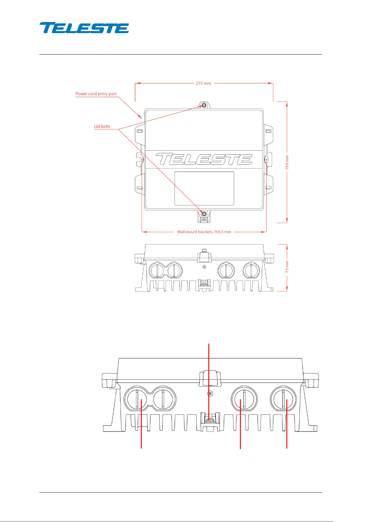
Input port
Output port 1
Ground lug
Output port 2
59300623 Rev.001
5.4.2018 4(20)
9817032
Interfaces
Figure 1. E3 housing dimensions – top and side view
9817024
Figure 2. Port locations
The E3 has three dedicated cable connection points: Input and two outputs.
User Manual E3
59300623 Rev.001
5.4.2018 5(20)
Coaxial connections
The E3 amplifier requires pin-type connectors for all RF connections. The E3
amplifier has spring loaded seizure assem blies on coaxial ports that provide a
tight connection with precise alignment between contact points. All coaxial
output ports have a standa rd PG11 thread. Note that Teleste KDC3 27 (PG11–
F) and KDC328 (PG11-3.5/12) connectors fulfils the centre pin equipment
requirement for E series.
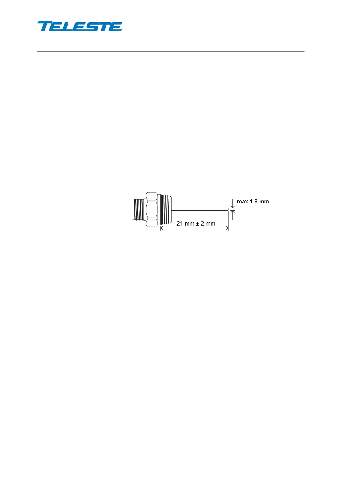
Suitable length for the centr e conductor pin is approxi mately 21 mm (Figure 3).
Pin-type connectors, with pins extending from 19 mm to 23 mm from the
connector shoulder, require no trimming. Any longer pins must be trimmed
before inserting them into the housing. After cutting the pin, trim the sharp
edges. Using connectors with centre conductors pins exceeding 1.8 mm in
diameter will permanently damage spring loaded seizure assemblies. Ensure
that the centre conductor pin is not def ormed, causing destruction of the spring
loaded seizure assem bly. Note! When using KDC31 4 (PG11-5/8) adapter, the
length of connector’s centre connector pin must be 33 mm ±2 mm.
9817016
Figure 3. Centre conductor length

User Manual E3
59300623 Rev.001
5.4.2018 6(20)
Powering
NOTE! Do not remove the shielding cover. There are no user
serviceable parts inside. Unauthorized repairs or modifications
result in permanent dam age to the equipment, and will void the
warranty.
Common precautions:
• The E3 amplifier is intended for installation in restricted access locations
(dedicated equipment rooms, equipment closet, or the like)
• Operate the device only on the specified supply voltage.
• The E3 must never be operated without its power supply unit shielding
cover.
• The E3 has no separ ate power switch thus the pow er plug must be easily
accessible.
• Disconnect the power cor d by the connector only. Never pull on the cab le
portion of the power cord.
• Do not place or drop heavy or sharp-edged objects on the power cord.
• The power must be disconnected when installing or removing the E3.
Additional safety requirements for Norway and Sweden:
Equipment connected to the protective earthing of the building installation
through the mains connect ion or through other equipm ent with a connection to
protective earthing an d to a cable distribution s ystem using coaxial cab le, may
in some circums tances create a fire hazard. Connect ion to a cable distribution
system must be prov ided thr ough a de vice provi ding electrical isol ation below a
certain frequency range (galvanic isolator, see EN 60728-11).
The E3 is available either with a remote or local powering option. The E3 has an
integrated power supply that cannot be replaced. The following subsections
describe the differences.
E3 with remote powering (27...65 V AC)
The supply voltage of the rem ote powered E3 model ( 27...65 V AC) is supplied
via input/output RF ports only. Feed through capacity is max. 7 A / port. On
delivery, RF ports are provide d with fuses. Local connection f or remote feed is
not possible thus the power cord entry port must be plugged.
E3 with local powering (205…255 V AC)
The locally powered E3 model is con nected t o the m ains voltage of 205…2 55 V
AC with its own power cord and has no fuses nor AC feed-through in its RF
ports. The power suppl y unit is double shielded and does not require separate
grounding. However, ensur e tha t the h ousing of th e E 3 is properly connec ted t o
the earth in order to meet safety requirements. Proper grounding will also
improve protection f rom the ef fec ts of interfer ence a nd thus increase the overa ll
reliability of the system.
 Loading...