

Teleste CXE851, CXE852 User Manual
User Manual CXE85X
59300464 Rev.005
9.12.2013 1(44)
CXX Series
User Manual
Teleste Corporation
CXE851 / CXE852
Single / Dual optical receiver
with Ethernet management

User Manual CXE85X
59300464 Rev.005
9.12.2013 2(44)
Contents
Introduction ........................................................................................................ 3
CXE85x generations ............................................................................................ 3
Installation .......................................................................................................... 4
Housing ................................................................................................................ 4
Powering .............................................................................................................. 5
Interfaces ............................................................................................................. 5
Fibre installation ................................................................................................... 6
Front panel ........................................................................................................... 7
Features .............................................................................................................. 9
Local user interface ............................................................................................. 9
RF performance ................................................................................................. 10
Establishing connection ..................................................................................... 13
Management interfaces ..................................................................................... 14
Viewer pages (SNMP interface) ...................................................................... 17
Status viewer page ............................................................................................ 18
Settings viewer page ......................................................................................... 19
Communication viewer page ............................................................................. 21
NTP viewer page ............................................................................................... 23
Alarm log viewer page ....................................................................................... 24
Monitoring viewer page ..................................................................................... 25
Properties viewer page ...................................................................................... 28
Web user interface........................................................................................... 29
Home WebUI page ............................................................................................ 29
Monitoring WebUI page ..................................................................................... 30
Log WebUI page ................................................................................................ 32
Communication WebUI page ............................................................................. 33
SNMP WebUI page ........................................................................................... 34
Time WebUI page .............................................................................................. 36
Properties WebUI page ..................................................................................... 37
Maintenace WebUI page ................................................................................... 38
CLI commands ................................................................................................. 40
Legal declarations ........................................................................................... 43

User Manual CXE85X
59300464 Rev.005
9.12.2013 3(44)
Introduction
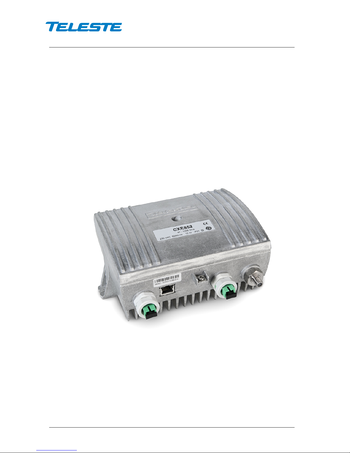
CXE851 is a single input fibre optical receiver and CXE852 is a dual input fibre
optical receiver. Both receivers can be monitored and controlled through
standard Ethernet interface using WebUI, SNMP and CLI interfaces. They are
designed for cases which don't need optical transmitter and only a downstream
signal is required.
CXE85x optical receivers feature an 1006 MHz bandwidth and integrated
optical receiver(s). The use of integrated optical receiver(s) eliminates timeconsuming mounting of connectors and fibre splicing inside the housing. The
optical receiver(s) supports light wavelengths from 1290 nm to 1600 nm.
Alignment of CXE85x is easy. The Optical Level Control (OLC) as well as gain
and slope adjustments use electrical controls that improve reliability. Installation
can be carried out using basic tools without any software. Local or remote
configuration using PC software is also possible, allowing fine-tuning the
product.
The RF output port is equipped with DC voltage connection controlled by
processor. It can be used to control external equipment, for example Ethernet
switch powering.
CXE852 and CXE851 differ only in one respect: CXE852 is equipped with two
optical receivers and provides either manual or automatic switchover between
the two inputs.
CXE85x generations
There are two CXE85x generations with some differences in hardware and/or
software functionality:
1
st
generation CXE85x:
• Manufactured until Q2/2013
• Two slope adjustment values: 0 dB / 10 dB
• Gain adjustment range 0…-15 dB (HW mode) / 0…-20 dB (SW mode)
2
nd
generation CXE85x:
• Manufacturing started Q2/2013
• Three slope adjustment values: Flat / Middle / High (0 dB / 7 dB / 9 dB)
• Gain adjustment range 0…-31 dB and additional "attenuator range"
selection jumper.
User Manual CXE85X
59300464 Rev.005
9.12.2013 4(44)
Installation
Housing
8912081
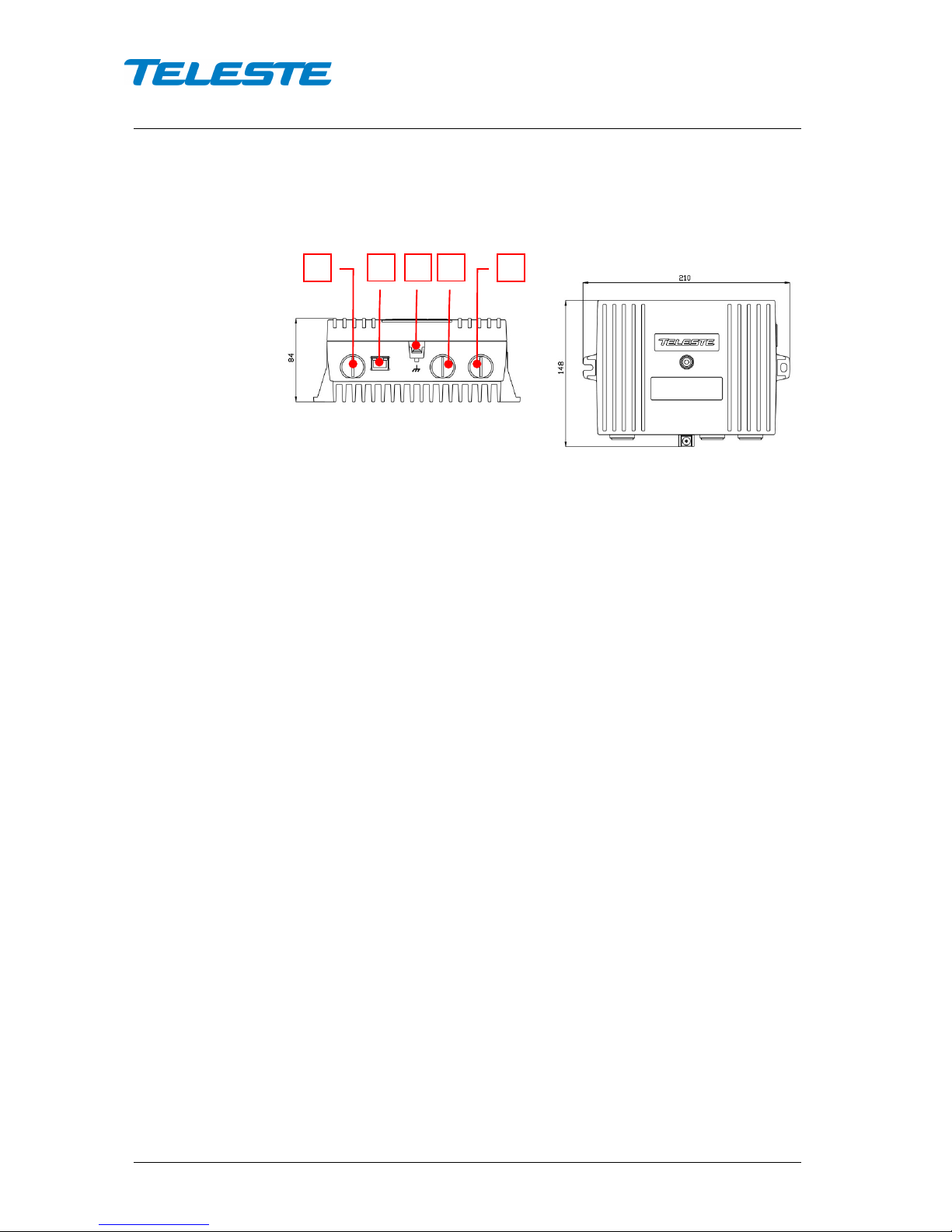
Figure 1. CXE85x Single / dual fibre optical receiver, 1) Optical fibre input port, 2)
Ethernet port, 3) Ground, 4) Optical fibre input port 2 (CXE852), 5) RF output port
The CXE85x can be installed either into a street cabinet or to a sheltered
outdoor environment. Note: The fibre adapter and the Ethernet port are not
waterproof. The CXE85x should be installed in a vertical position so that the
connectors are underneath. At least 100 mm of free space should be left above
the amplifier to ensure sufficient cooling air circulation. The housing should be
with at least 4 mm
2
grounding wire (Cu) from a proper earth to the grounding
point.
1
2 3 4
5
User Manual CXE85X
59300464 Rev.005
9.12.2013 5(44)
The lid of the housing is secured by a single bolt. There are no hinges. Open lid
should be removed completely. Using 4 mm Allen key, the retaining bolt is
fasten with a tightening torque of 2.5...3.5 Nm. Before closing the lid ensure
that:
- nothing is trapped between the lid and the case
- all case gaskets are in their correct positions
- lid seats evenly on the rubber gasket
The class of enclosure is IP31 when correctly installed and tightened.
Powering
The locally powered CXE85x fibre optic receiver is connected to the main
voltage of 165…255 V AC via its own power cord. The power supply is double
shielded and does not require separate grounding. However, the amplifier
housing has to be grounded from the grounding point. The supply voltage fuse
is located on the upper right corner of the amplifier, beneath the shroud of the
power supply unit. To replace the fuse:
- disconnect the power before removing the shroud of the PSU
- identify and clear the condition that caused the original fuse failure
- replace the fuse, the fuse is of the type T3.15 A / 250 V / TR5
- refit the shroud
Interfaces
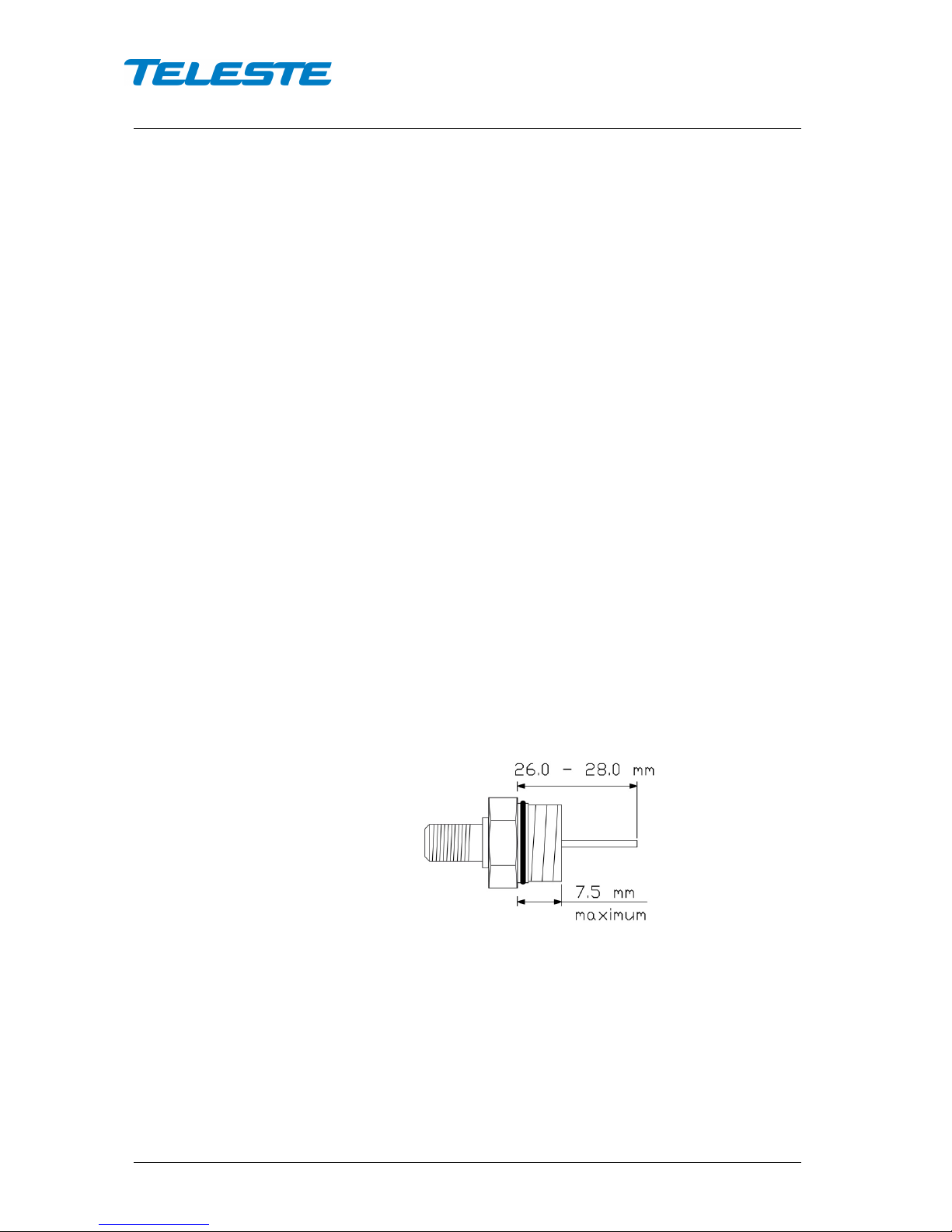
Underneath the CXE85x there is one/two optical fibre input(s) and one RF
output. The RF output has a standard PG11 thread and accepts any KDC type
adapter or connector. Figure 2 illustrates the centre conductor. RF output port is
factory installed with F female adapter.
8910036
Figure 2. Centre conductor length
The CXE85x can be connected to Local Area Network (LAN) via a standard
(RJ45) 10/100Base-T Ethernet connection (Figure 1 pos. 2).

User Manual CXE85X
59300464 Rev.005
9.12.2013 6(44)
Fibre installation
The CXE85x comes as standard with a bulkhead mounted SC/APC adapters.
Fibre installation is a critical procedure and it should be done with care.
Incorrect handling of the fibre can result in damage and degraded performance.
Warning: The SC/APC adapter is connected to the integrated fibre receiver
through a short length of fibre on the rear side of the bulkhead. To avoid
damage to the fibre, take care not to rotate the adapter when installing or
removing the fibre connector.
Cleaning fibre connectors
• For correct optical operation ensure that all optical connectors are cleaned
immediately before mating using a suitable optical connector cleaning kit.
• If a cleaning kit is not available, wipe the end of the connector using pure
isopropyl alcohol (99%) and a lint-free wipe. Dry it with filtered compressed
air. Wait until dry to insert connector into the adapter.
• When fibre optic connectors are unmated, the optical fibre end faces must
be protected from contamination using suitable dust caps. Contamination of
fibre end faces will reduce the performance of the optical fibre and could
ultimately cause failure of the system. Contamination could also damage the
fibre end faces when the connectors are mated.
User Manual CXE85X
59300464 Rev.005
9.12.2013 7(44)
Front panel
8913048
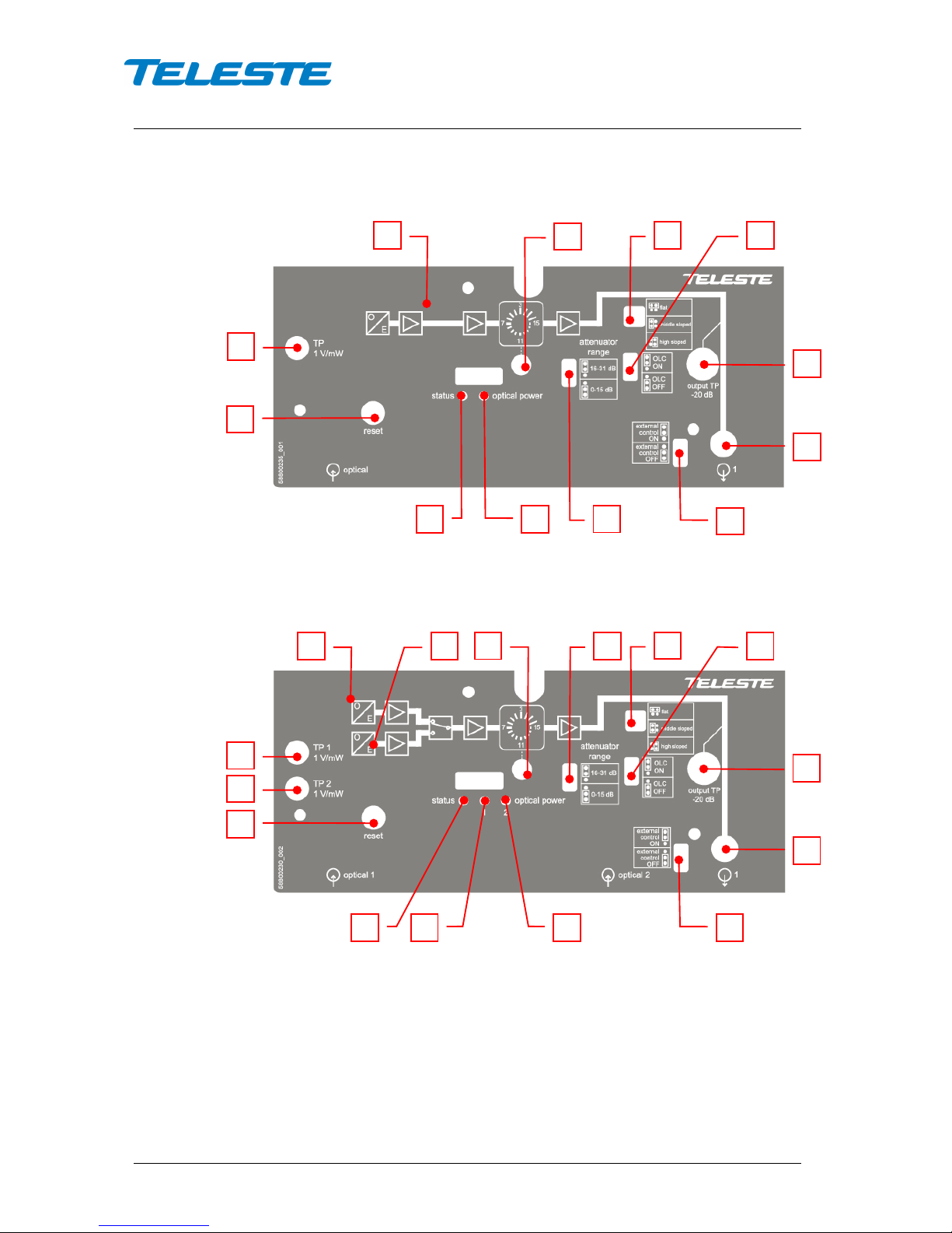
Figure 3. CXE851 front panel (2
nd
generation)
8913055
Figure 4. CXE852 front panel (2
nd
generation)
1) Integrated optical receiver 1
2) Integrated optical receiver 2 (CXE852)
3) Optical power DC voltage test point 1
4) Optical power DC voltage test point 2
(CXE852)
5) Mid stage attenuator
6) Mid stage attenuator range jumper
7) Slope selection jumper
8) OLC mode jumper
9) Output test point, -20 dB directional
coupler
10) RF output
11) External control jumper
12) Status LED
13) Optical input power 1 LED
14) Optical input power 2 LED
15) Reset button
1 2 3 4 7
15 8 9
12
13
14
11 1 3 5 7 8 9
11
13
12
15 5 10 6 10
6
User Manual CXE85X
59300464 Rev.005
9.12.2013 8(44)
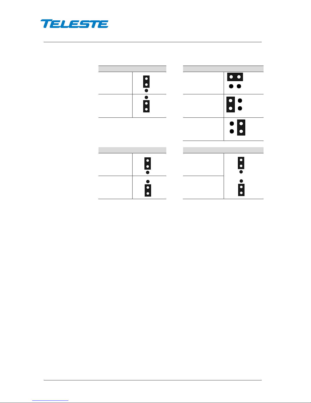
Attenuator range (Fig. 3/4 pos. 6)
Slope selection (Fig. 3/4 pos. 7)
16-31 dB
Flat
0-15 dB Middle sloped
High sloped
OLC mode jumper (Fig. 3/4 pos. 8 )
External control jumper (Fig. 3/4 pos. 11)
OLC ON
External control ON
OLC OFF External control OFF
Figure 5. Jumper configurations
User Manual CXE85X
59300464 Rev.005
9.12.2013 9(44)
Features
Local user interface
The local user interface consists of two/three status LEDs for optical input
power and general status, a reset button, a rotary switch for midstage gain
setting, three jumpers for setting the output slope, gain adjustment range and
controlling the OLC and one jumper controlling the DC voltage connection at the
RF output port.
LEDs
The optical input power LED is red when the optical input power has a major
alarm (i.e. is outside major alarm limits), yellow when it has a minor alarm (i.e.
between major alarm limits but outside minor alarm limits), otherwise green.
The status LED is red when there is at least one major alarm related to RF
output power, temperature, local power supply or internal error. It is yellow
when there are no major alarms but at least one minor alarm. Otherwise it is
green.
The status LED blinks when the RF controls are under software control and
changing the rotary switch or jumpers has no effect. Hardware control can be
restored using the reset button.
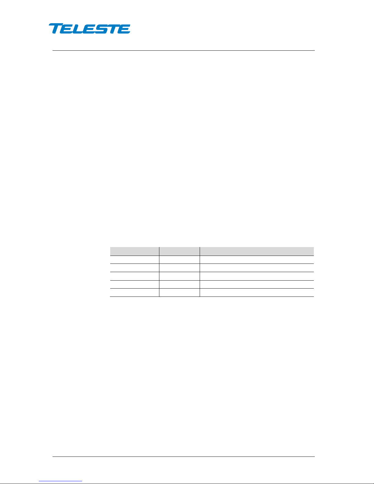
Reset button
The reset button can be used to restore RF controls to hardware control, to
reset communication settings back to factory values or to reset all settings back
to factory values.
Button pressed
Status LED
Action when released
<1 s
dark - 1...5 s
green
RF controls return to hardware control
5...10 s
yellow
Communication settings are reset
10...15 s
red
All settings are reset to factory values
>15 s
dark
-
Table 1. Reset button functions
When the button is released while the status led is green/yellow/red, the status
LED blinks briefly in the same colour to indicate successful operation.
The communication settings reset enables DHCP and sets SNMP communities
to read:public and write:private. This can be used to e.g. restore communication
with a device whose IP address is unknown.
RF controls
The rotary switch can be used to attenuate output level in 1 dB steps between
0...15 dB. 2nd generation devices feature two attenuation ranges (0…15 dB or
16…31 dB) to adjust the output level. The attenuator ranges are selected using
the attenuator range selection jumper.
OLC can be disabled with a jumper for high output level applications. When
disabled, the input attenuator is set equivalent to -4 dBm input power.
Output slope can be selected between flat, middle or high with a jumper. The
middle option is available only with 2
nd
generation devices.
User Manual CXE85X
59300464 Rev.005
9.12.2013 10(44)
The status led blinks when the RF controls are under software control and
changing the rotary switch or jumpers has no effect. Hardware control can be
restored using the reset button.
RF output port
RF output port features an “open collector output” for purposes of alarming or
control signal output. The function is controlled by processor and can be used
for example to reset an external Ethernet switch installed next to CXE85x.
CXE85x measures the time elapsed since last received unicast packet to its IP
address. If CXE85x does not receive any unicast packets within user-specified
time, the control signal output is activated for user-specified time and the
unicast receive time calculation is restarted.
Although the open collector output allows a lot of wiring flexibility, care must be
taken not to destroy the circuit via over-voltage, transients or current overload.
Open collector output is specified for max. 100 mA switching current (30 VDC
max.). Inductive loads (relays or other solenoids) can generate very high
voltage spikes when the open collector switch is turned off. If such a load is
unavoidable, the use of transient suppression components parallel to the load is
required. This is critical, as a single transient pulse may destroy the output.
Note: If the control signal output functionality is not used the external control
jumper (Fig. 3 pos.10) must be set to OFF state
RF performance
Optical receivers are integrated within the CXE85x and will accept both 1310
and 1550 nm wavelength optical inputs. Each optical receiver have both a LED
indicator and DC voltage test point for measuring received optical power.
The output stage uses a GaAs MESFET output amplifier to improve RF
performance over the entire 47 to 1006 MHz passband.
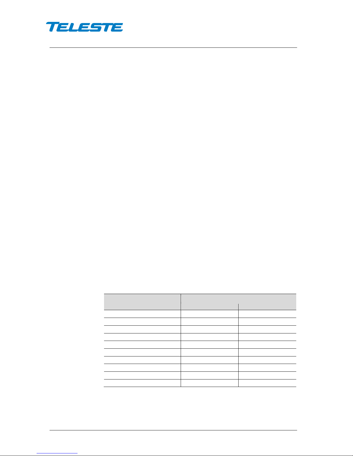
Optical input power
Optical input power can be measured from the optical power DC voltage test
point (Figure 4 pos. 3, 4). The test point DC voltage is directly proportional to
optical input power in mW e.g. 1 V corresponds to 1.0 mW average optical
power in 1310 nm operation. In 1550 nm operation subtract 0.5 dBm.
Optical input power / dBm
Optical power testpoint / VDC
1310 nm
1550 nm
+2
1.58
1.78
+1
1.26
1.41
0
1.00
1.12
-1
0.79
0.89
-2
0.63
0.71
-3
0.50
0.56
-4
0.40
0.45
-5
0.32
0.35
-6
0.25
0.28
-7
0.20
0.22
Table 2. Optical input power DC test point voltages
Do not connect any voltage to the test point or short circuit it to ground. Use a
voltage meter with an input resistance higher than 100 kΩ.
User Manual CXE85X
59300464 Rev.005
9.12.2013 11(44)
Optical input selection
The CXE852 optical input selection can be set to 3 modes: Automatic, Manual
1, Manual 2.
When the input selection is set to the “Automatic” mode, the node automatically
selects the optical input according to signal conditions. If the optical input power
at the main input is out of major alarm limits, input 2 will be selected provided
that its optical input power is inside major alarm limit + deadband. Input 1 is
selected when its optical input power is above low major alarm limit +
deadband. This fully automatic input selection between the two inputs offers a
useful redundancy mode for critical applications.
In “Manual: RX #1” mode input 1 is always used, regardless of the optical input
power. In “Manual: RX #2” mode input 2 is always used, regardless of the
optical input power.
Forward path adjustment
The following are instructions to be used for a normal adjustment procedure.
1. Test the optical input power present on the fibre using an optical power
meter. The CXE85x optical input power range is from -7 dBm to +2 dBm.
2. Optical Level Control (OLC) circuitry provides gain control that
compensates for changes in input level caused by external variations. The
available gain reserve is factory-set for optimum operation. If needed the
output level can be adjusted with the mid stage attenuator. It is possible to
disable the OLC with a jumper (Figure 4 pos. 8) or via software. This makes
it possible to operate the CXE85x at full gain for applications that do not
require gain stabilization.
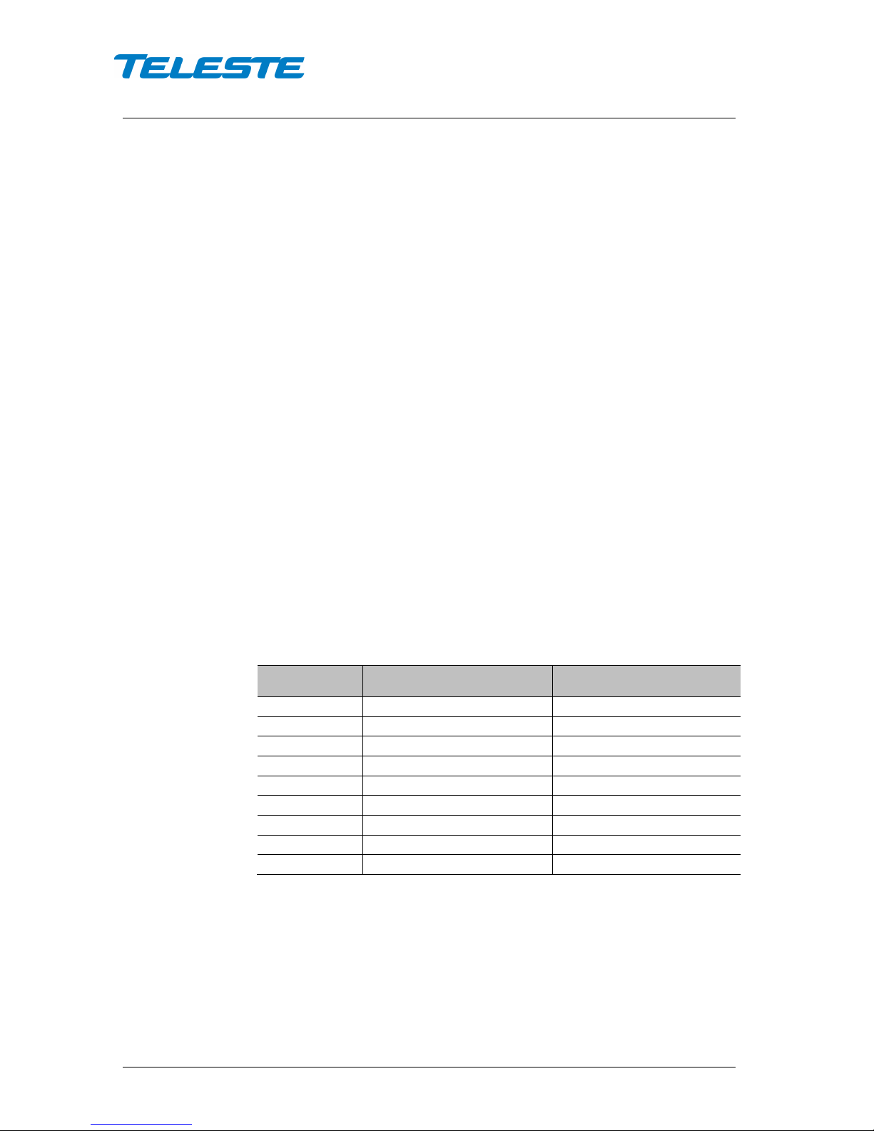
3. Use the mid stage attenuator to get wanted output level. The network plan
should specify exact signal levels. Refer to the "Table 3. Mid stage
attenuator selection and output level".
4.
Mid stage
attenuator
OLC enabled
-7...+2 dBm @ 4 % OMI
OLC disabled
-4 dBm @ 4 % OMI
0 dB
115 dBµV
116 dBµV
1 dB
114 dBµV
115 dBµV
2 dB
113 dBµV
114 dBµV
3 dB
112 dBµV
113 dBµV
… … …
15 dB 100 dBµV 101 dBµV
16 dB
99 dBµV
100 dBµV
… … …
31 dB 84 dBµV 85 dBµV
Table 3. Mid stage attenuator selection and output level
5. Use the slope selection jumper (Figure 4 pos. 7) to select the mid stage
slope.
6. Apply the power.
7. Connect the fibre connector to the bulkhead adapter.

User Manual CXE85X
59300464 Rev.005
9.12.2013 12(44)
Forward path adjustment via software
The mid stage gain, OLC enabling and slope setting can be taken into software
control. When software control is enabled, the rotary switch and jumpers have
no effect. Hardware control can be restored with reset button or via software.
There are two software control modes: manual and OMI-based. The difference
between these is in how gain is controlled. In manual mode the gain can be set
as via hardware, -15...0 dB in 1 dB steps. In newer software releases this range
is -20…0 dB for 1
st
generation devices, and -31…0 dB for 2nd generation
devices. In OMI-based mode the CXE85x calculates the correct gain based on
the user-specified transmitter OMI-% and target output level.
RF output power
CXE85x measures its RF output with a wideband RF detector. The result is
displayed in (approximate) dBm reading, but due to the detector frequency
response curve and calibration issues, no accuracy specification is given. The
factory default setting for the alarms is only low minor alarm enabled at -15
dBm. All alarm limits and enables can be edited by the user, and there is a
shortcut button in the UI for setting the alarm limits to ±3 and ±6 dB from the
measured value.

User Manual CXE85X
59300464 Rev.005
9.12.2013 13(44)
Establishing connection
Ethernet port
The Ethernet port of CXE85x supports both 10 and 100 Mbps half and full
duplex standard Ethernet connection. The port has a Auto-MDI/MDI-X feature,
thus the connection between CXE85x's RJ-45 port and a PC or Ethernet switch
can be made with either straight or crossed cable.
There are two LEDs in the RJ-45 connector:
− Green led: Link OK, blinking means activity
− Yellow led: Speed 100 Mbps
DHCP / AutoIP
CXE85x can be configured to obtain its IP address automatically with its built-in
DHCP client. Another possibility is to manually set the IP settings.
The DHCP client makes it possible to install the unit without a PC, without
making any communication settings. Only plugging in the Ethernet cable,
checking that the green link led lights up and writing down the MAC address is
needed. The MAC address is visible on the sticker next to CXE85x's Ethernet
port and can later be used to identify the unit and assign it correct IP address
via the DHCP server configuration.
The DHCP client with AutoIP feature is enabled by default and has essentially
the same functionality than in e.g. Windows PC. First the DHCP client tries to
connect to a DHCP server to obtain an IP address, netmask and gateway
settings. If CXE85x is not able to find a DHCP server within ~1 minute, it uses
the AutoIP feature: sets netmask to 255.255.0.0 and finds the first free IP
address in the AutoIP address space, usually 169.254.1.1.
A Windows XP / Vista / 7 / 8 PC in a typical configuration (DHCP enabled) uses
the same AutoIP range it if cannot find a DHCP server. Thus the initial
configuration of a CXE85x is simple: established communication link by simply
connecting the PC and CXE85x together with a straight or crossed Ethernet
cable.
Depending on the PC settings, it may require up to minute or two for the DHCP
client to fail and go to AutoIP mode. Some systems may in certain situations
even require that the Local Area Connection is briefly disabled and enabled
again via Control Panel.
Initial connection to CXE85x can be naturally established also by manually
configuring the PC's IP address settings so that it belongs to the AutoIP subnet,
i.e. IP 169.254.x.y and netmask 255.255.0.0.
Note that the AutoIP subnet is not routable, thus it requires a direct cable
connection between PC and CXE85x.

User Manual CXE85X
59300464 Rev.005
9.12.2013 14(44)
Manual IP settings
When the initial connection to CXE85x has succeeded, its IP settings may be
configured manually. The factory default settings are the same than in AutoIP,
see "Table 4. Default communication settings".
Parameter
Default setting
IP address (static)
169.254.1.1
Netmask (static)
255.255.0.0
Gateway (static) 0.0.0.0
DHCP & AutoIP
Enabled
SNMP read community
public
SNMP write community private
Table 4. Default communication settings
There are two sets of IP/mask/gateway parameters: the ones is use (read-only)
and the ones configured manually. The manually configured settings are taken
into use when the 'IP address configuration' is commanded to manual mode. At
this point the settings' validity is checked. If any of the following is true, IP
address configuration mode is internally changed back to DHCP/AutoIP:
− IP address is 0.0.0.0
− Netmask is 255.255.255.255 or illegal, e.g. 255.128.255.0
− Default gateway address is not in the same subnet
The reset button can be used to restore factory default communication settings
if communication to the unit is lost due to e.g. unknown IP address.
Management interfaces
SNMP communication
CXE85x's SNMP agent uses the factory default communities read: public and
write: private.
The recommended configuration tool for CXE85x is Teleste CATVisor
Commander. Viewer package DUS100 version 4.23 and above contain SNMP
viewer for CXE85x, for detail see "Viewer pages" chapter.
To establish communication with CATVisor Commander, select "Remote" /
"SNMP Element" from the "Add new connection" dialog, then enter the IP
address and correct SNMP communities.
It is also possible to use a 3rd party SNMP browser / manager software to
control and monitor CXE85x. The required Teleste SNMP MIBs can be
downloaded from Teleste Club and SCTE MIBs from SCTE website.
CXE85x can send SNMP traps to 2 separate IP addresses, with separate trap
community and port settings. The trap sending behaviour can be fine-tuned with
delay, interval and lifetime parameters.
The reset button can be used to restore factory default communication settings
if communication to the unit is lost to for example unknown SNMP community.
 Loading...