

Teleste CXE280 User Manual
User Manual CXE280
en
de
02
11
59300460 Rev.002
17.12.2013 1(20)
CXE Series
CXX Reihe
User Manual
Bedienungsanleitung
Teleste Corporation
CXE280
Universal amplifier
Universal Verstärker

User Manual CXE280
59300460 Rev.002
17.12.2013 2(20)
Contents
Introduction ........................................................................................................ 3
Technical specifications ................................................................................... 4
Block diagram .................................................................................................... 5
Installation .......................................................................................................... 5
Housing ................................................................................................................ 5
Interfaces ............................................................................................................. 6
Powering .............................................................................................................. 6
Front panel ........................................................................................................... 7
Jumper settings ................................................................................................... 8
Adjustments ....................................................................................................... 8
Legal declarations ........................................................................................... 10

User Manual CXE280
59300460 Rev.002
17.12.2013 3(20)
Introduction
The CXE280 is a compact dual output amplifier. It has two gain modes in one
product. Gain can be selected on the field according to wanted operation.
Higher gain (40 dB) is designed for distribution purposes and lower gain
(32 dB) is suitable for line extender use. Return path gain can also be selected
by switching one amplifier stage. The CXE280 house distribution amplifier
supports 1 GHz frequency range in the downstream.
All signal controls are using standard attenuator pads to minimize the selection
of spare plugs. Amplifier stages at output are using GaAs-FET technology,
which guarantees the highest CTB and CSO performance with optimal power
need. Other standard features include reliable power supply as well as an
efficient surge and ESD protection.
Caution!
− Services and repairs should only be carried out by
authorised personnel.
− Do not touch live parts.
− The amplifier has no separate power switch thus
the power plug must be easily accessible.
− The power must be cut when installing or removing the
amplifier.
− The amplifier must not be operated without its Standard fitted
power supply unit protection cover. The lid must be closed.

User Manual CXE280
U
max(112 QAM channels)
-8
All specifications are subject to change without notice
59300460 Rev.002
17.12.2013 4(20)
Technical specifications
Downstream signal path
Frequency range 85...1006 MHz
Return loss 18 dB
Gain 40 / 32 dB
Input attenuator control range 0...-20 dB, 1 dB step
Input equaliser control range 0...22 dB, 1 dB step
Cable simulator 0…9 dB, 1 dB step
Mid-stage slope 0…10 dB, 1 dB step
Mid-stage gain 0…-10 dB, 1 dB step
Flatness ± 0.5 dB
Test point input / output -20 dB
Noise figure 5.5 dB
109.5 dBuV
Output level, CTB CENELEC 41 ch 112.0 dBμV
Output level, CSO CENELEC 41 ch 113.0 dBμV
Output level, XMOD CENELEC 41 ch 109.0 dBμV
Upstream signal path
Frequency range 5... 65 MHz
Return loss 18 dB
Gain 32 / 22 dB
Input / output gain control 0…-20 dB, 1 dB step
Output equaliser 0…12 dB, 1 dB step
Flatness ± 0.8 dB
Return test point -20 dB
Noise figure 3.7 dB
Output level, DIN 45004B 119.0 dBµV
BER | MER
General
Power consumption (high gain / low gain) 14.5 W / 13.5 w
Supply voltage 26… 65 V AC / 180…255 V AC
Input / Output connectors PG11 (several adaptors available)
Test point connector F female
Dimensions (h x w x d) 182 (210) mm x 140 (148) mm xx 84 mm
Weight 1.5 kg
Operating temperature -40...+55 °C
Class of enclosure IP 54
EMC combatibility | Safety EN 60728-2 | EN 60728-11
Additional EMC tests for RF ports ESD 4 kV / Surge 6 kV
< 1 x 10
| > 35 dB
User Manual CXE280
IN OUT 1
TP -20dB
TP -20dB
AC
dB
AC
OUT 2
AC
TP
Cable Simulator
dB
dB
dB
High gain /
Low gain
High gain /
Low gain
59300460 Rev.002
17.12.2013 5(20)
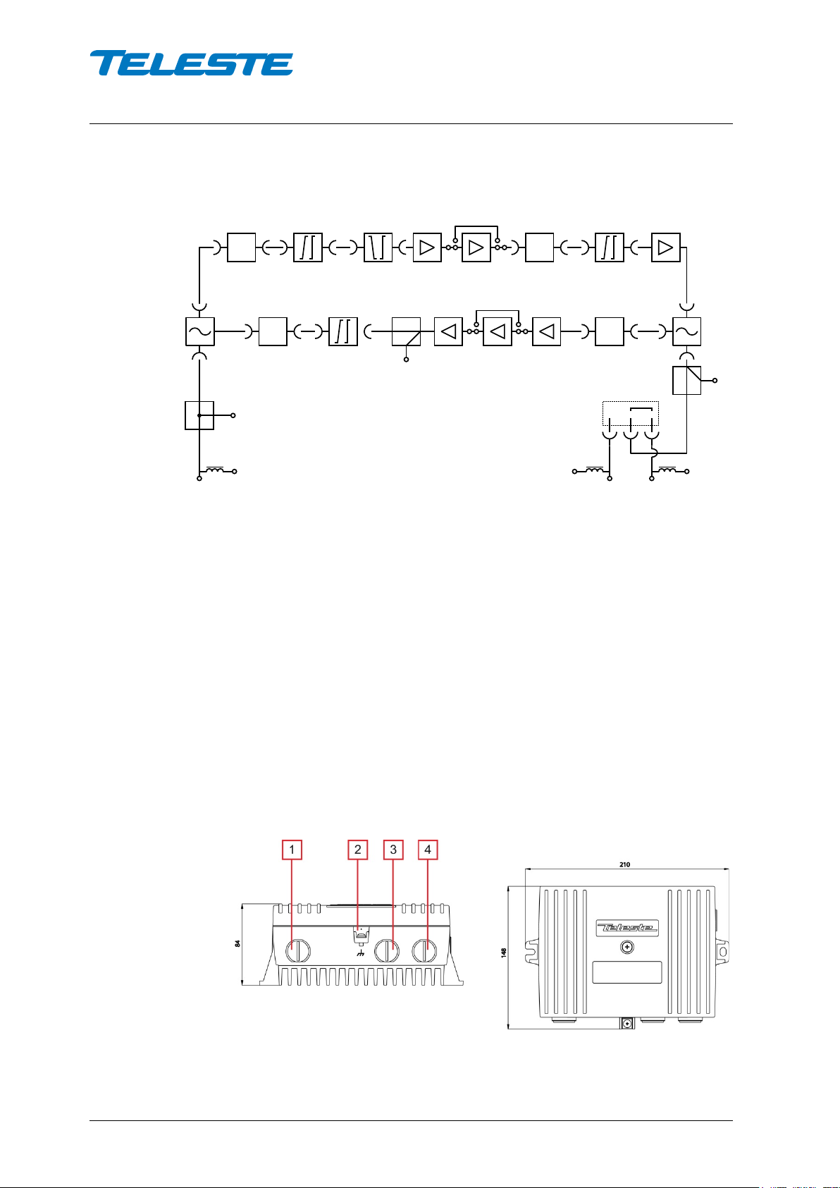
Block diagram
Installation
Housing
The amplifier can be installed either into a street cabinet or to outdoor
environment. The amplifier should be installed in a vertical position so that the
external cable connectors are underneath. At least 100 mm of free space
should be left above the amplifier to ensure sufficient cooling air circulation. The
class of enclosure is IP 54. Note, used connector type might have lower IPclassification than the amplifier housing.
The cover of the housing is closed by a single bolt. There are no hinges. Open
cover is to be removed completely. Using 4 mm Allen key, the retaining bolt is
fasten with a tightening torque of 2.5...3.5 Nm. To ground the amplifier housing
connect at least 4 mm
2
grounding wire (Cu) from a proper earth to the
grounding point.
NOTE! Make sure the input attenuator adjustment (Figure 4 pos. 4) is at its
minimum level before connecting power to the amplifier.
8910044
Figure 1. CXE280 amplifier
1) Input, 2) Ground, 3) Output port 2, 4) Output port 1
User Manual CXE280
AC GND
led
59300460 Rev.002
17.12.2013 6(20)
Interfaces
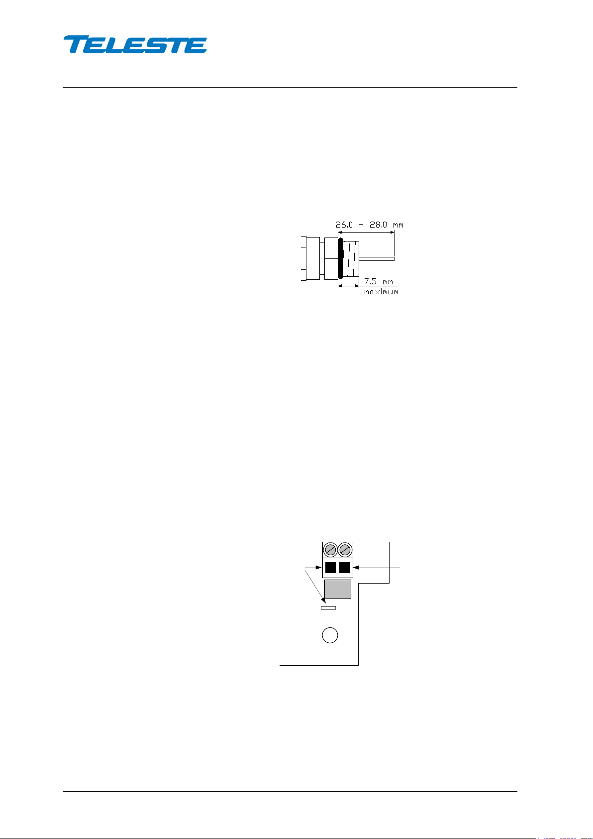
Underneath the CXE280 amplifier there are three cable connection points: input
and two outputs. The amount and function of actual connectors varies with the
chosen configuration. All coaxial connection points have a standard PG11
thread and they accept a KDC type adapter or connector. Available connector
types are F, IEC, PG11, 5/8” and 3.5/12.
8905010
Figure 2. Centre conductor length
Powering
The supply voltage of the remote powered amplifier (26...65 V AC or ± 30...90 V
DC) can be fed through either of the output ports (Figure 1 pos. 3 & 4) or the
input port (Figure 1, pos. 1). Make sure the remote powering jumpers (Figure 4,
pos. 20 & 21) are in the correct positions for remote powering. Refer to
Figure 6. External power can also be fed through the amplifier into the network
by moving remote powering jumpers of the output ports to “on” position.
Maximum feed-through current is 3 A per port (6 A total).
Note that the external wiring connected to terminals that are hazardous live
requires installation by an instructed person. Because the amplifier is not
equipped with an all-pole mains switch, the powering shall be carried out in
accordance with all applicable installation rules. The power intake of the remote
powered amplifier may also be done externally via the cable feed-through that is
located on the upper right corner of the amplifier (Figure 3). The protective fuse
is located on the left hand side of the power supply board.
8904054
Figure 3. Remote cable connector
The locally powered amplifier is connected to the mains voltage of
180…255 V AC via its own power cord. The mains power supply is double
shielded and does not require separate grounding. However, the amplifier
housing has to be grounded from the grounding point. The supply voltage fuse
is located on the upper right corner of the amplifier, beneath the shroud of the
power supply unit.
 Loading...