

Page 1
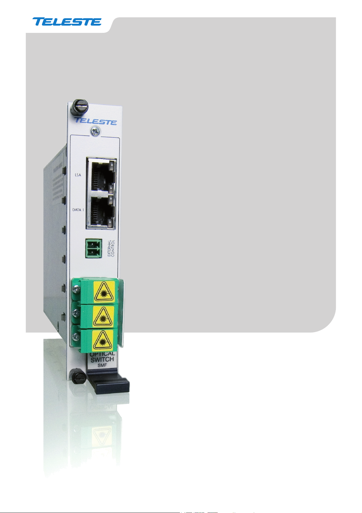
User Manual
Optical switch
For CFO series (CEV/x61/x71)
1 x 2 switch for singlemode fi bre
(1290-1330 and 1470-1610 nm) wavelenghts
Video Networks
Optical switch user manual, 59300281, rev001
Page 2

Welcome, and thank you for purchasing Teleste’s video networking products
Contents
Optical switch introduction .....................................................................................................................................1
General .............................................................................................................................................................. 1
Frame installation ...............................................................................................................................................1
Stand-alone installation ......................................................................................................................................1
Fibre connection ................................................................................................................................................. 1
Operation ...................................................................................................................................................................2
Link Source Alarm (LSA) .................................................................................................................................... 2
LSA commands .................................................................................................................................................. 2
Switch port positions and indicator leds ............................................................................................................. 2
Settings ......................................................................................................................................................................3
Wiring example................................................................................................................................................... 3
DIP switch settings ............................................................................................................................................. 3
LSA switching logic ............................................................................................................................................ 4
Application example ........................................................................................................................................... 5
Technical specifi cations .....................................................................................................................................5
Optical switch user manual rev001
Page 3
Optical switch introduction
Optical switch for CEV and CFOx61/x71 series
video modems.
LSA
DATA 1
EXTERNAL
CONTROL
1
2
3
4
5
6
General
Optical switch is compatible with CEV / CFOx61/x71 series video
modems and is used to achieve the fi bre path redundancy. The optical
bandpass covers CWDM wavelenghts 1460...1620 nm and standard 1310
nm window. Fully bi-directional optical operation is allowed. When optical
switch is used in conjunction with a CEV / CFOx61/x71 video modems,
the optical switching can be automatic when it is controlled by the Link
Loss Alarm (LSA) available from these video modems. Alternatively the
optical switch can be confi gured to operate in case of system power loss
or to have remotely controlled switching by means of an external I/O
control. The switching component itself is a durable 1 x 2 type nonlatching switch with a low insertion loss. The unit is 5HP wide.
Frame installation
The unit is to be pushed along the guide rails into the installation frame
(e.g. CSR216 or 316 series) and secured with the two locking screws. The
unit can be freely positioned in any slot in the frame. The empty positions
in the frame should be blanked off with cover plates.
to be provided by a CPS384 or CPS390 power supply unit.
The supply voltage is
Stand-alone installation
7
OPTICAL
SWITCH
SMF
8
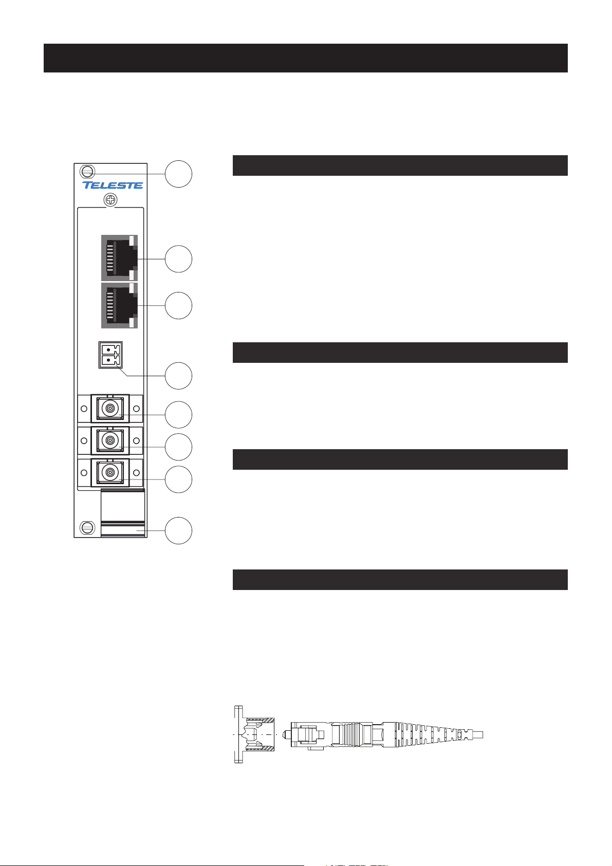
Optical switch, front view.
1. Locking screw (2 pcs)
2. LSA connector
3. Loopthru connector
4. External control connector
5. Port A
6. Port B
7. Comm o n p o r t
8. Handle (with unit information)
LSA and DATA1 port connectors are
of type RJ-45 female.
All optical port connectors are of type
SC/APC female (8°).
See further information on
dedicated sections.
The unit can be installed for stand-alone use by using a CMA series
module adapter. The unit is to be pushed along the guide rails into the
CMA module adapter and secured with the two locking screws. The
stand-alone unit should be mounted to a vertical surface. The 12V DC
supply voltage is supplied by the means of a separate mains adapter
with a regulated output, (e.g. CPS231).
Fibre connection
When installing the fi bre optic cable, do not exceed the minimum
bending radius when connecting cable to the system.
For correct optical operation ensure that:
> Protect opened connectors always with dustcaps
> Only 8° angle polished SC/APC connectors are allowed
> Clean all connectors before mating by using metyl or
isopropyl alcohol and dry connectors by compressed air
SC/APC 8° optical connection.
Optical switch user manual rev001 1
Page 4
Operation
Link Source Alarm (LSA)
CEV / CFOx61/x71 series video modem’s (transmitter and receiver)
contact closure output can be used to control optical switch when the
video modem’s LSA (Link Source Alarm) mode is enabled. When
operating with LSA, a connection cable is required between the optical
switch and video modem.
LSA on / off
LSA delay
LSA holdtime
LSA reset
Note! Enabling LSA (LSA ON) overrides all other functions of
modem’s
When LSA is enabled, video modem’s contact closure input and data 1
connections are normally available via optical switch’s DATA 1 (loopthru)
connector when using a connection cable between CEV /
series video modem and optical switch. The recommended connection
cable is Teleste CIC702 (RJ-45/RJ-45).
CC output.
video
CFOx61/x71
LSA commands
CEV / CFO16x/17x series video modem includes a command line
interface (CLI) for confi guration purposes. With help of CLI commands
you can confi gure the LSA settings. See CEV / CFO16x/17x series
video modem’s user manual for more details how to use the CLI.
: Enables/disables LSA monitoring on the device
: Displays or sets the link source alarm switching delay (in seconds).
Delay defi nes how long the device will wait for the optic link to get up
before operating the switch for the fi rst time
: Displays or set the link source alarm hold time (in seconds). Holdtime
defi nes the waiting time to ensure the recovery of the optical link
: Resets device source alarm to it’s initial state (see page 4 for
switching logic fl ow chart)
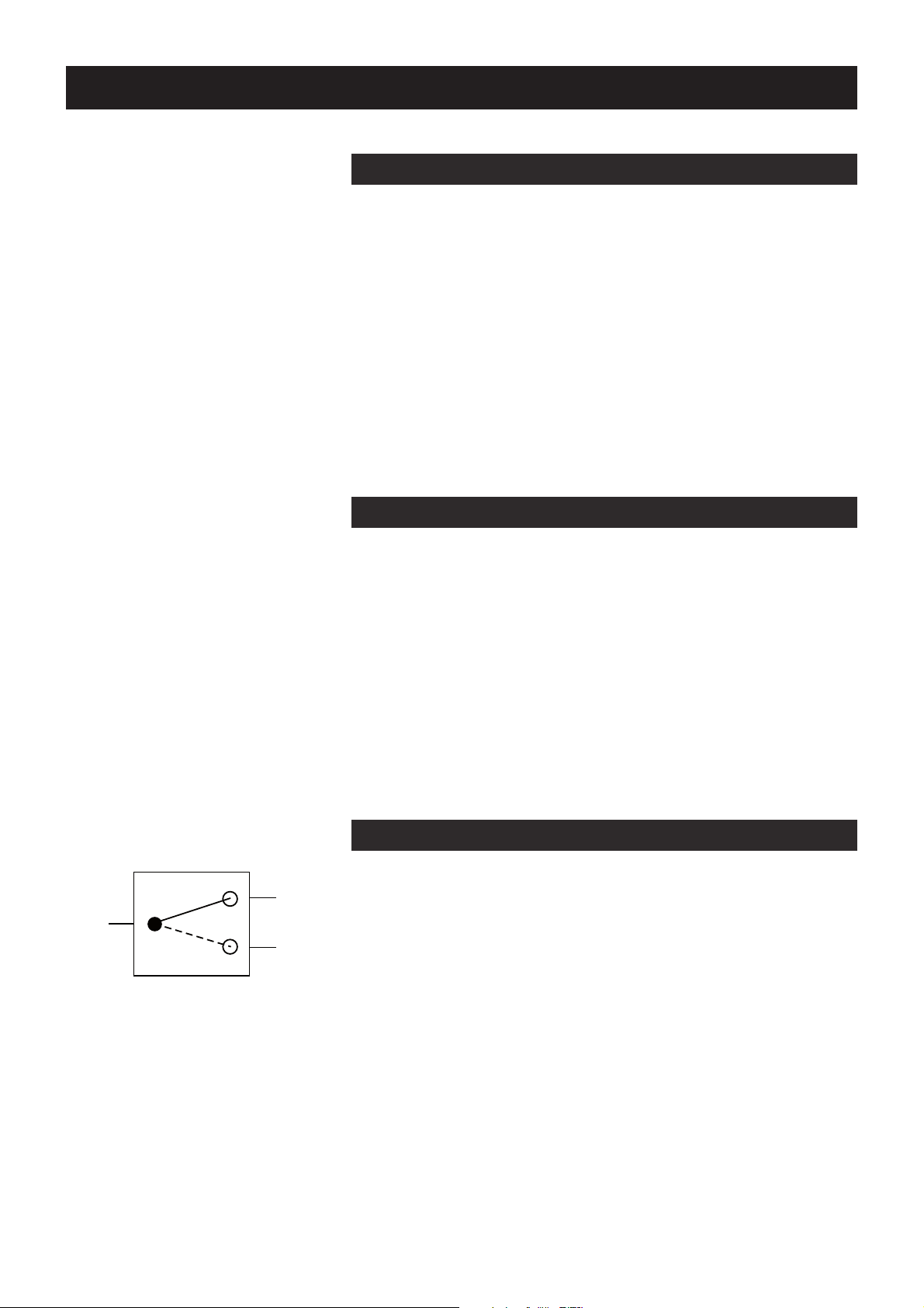
Switch port positions and indicator leds
When the switch is not activated (initial state), the com port is connected
Port A
to port A, and all front panel RJ-45 connectors leds (1-4) are dark.
Com
Port B
COM port positions.
The optical switch’s initial state is
always port position A, except when
using system power switching mode,
at that control mode the switch’s
initial state is position B.
2 Optical switch user manual rev001
When the switch is activated (alarm state), the com port is connected to
port B and all front panel RJ-45
The switching can be controlled by the following ways:
• LSA (contact closure output at video modem)
• System power fail (rack power supply)
• External control open (pins open)
• External control closed (pins closed)
• Remote controlled via video modem link
(normal contact closure operation, see note on the right)
Note! When using LSA control, the optican switch operates
automatically with the logic descripted in page 4.
connectors
leds (1- 4) are green.
Page 5
Settings
Wiring example
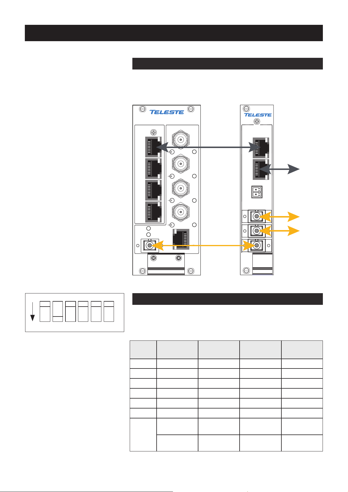
When the connection cable is connected between video modem and
optical switch, the video modem’s DATA 1 and contact closure connections
are available via the optical switch’s DATA 1 (loopthru) connector.
OPTICAL TRANSMITTER
Connection cable
(direct connected
e.g. CIC702)
VIDEO 1
LSA
1ON 23456
DATA 1
VIDEO 2
Video modem’s
data 1 & CC,
AUDIOMGMT DATA DATA / CCL
STATUS
LINK
MODULE
VIDEO 3
VIDEO 4
Fibre
patch cable
(see video modem
EXTERNAL
CONTROL
user manual for
pin configuration)
(e.g. OPA112)
ETHERNET BRIDGE
OPTICAL
SWITCH
SMF
Wiring example with four channel video transmitter.
DIP switch settings
There are several ways to control optical switch. The desired control
mode can be selected by the means of DIP switches (see settings
below). The default factory setting is LSA controlled.
Loopthru
Port A
Port B
DIP swithes are located on the
bottom of unit.
Note! When the optical switch is
confi gured to LSA mode, there is an
alternative possibility to control the
switch remotely. At the video modem
DIP
switch
1 OFF ON OFF OFF
2 ON OFF OFF OFF
3 OFF OFF OFF OFF
4 OFF OFF OFF OFF
LSA
controlled
EXT
mode A
EXT
mode B
System
power
confi guration session (CLI) the LSA
function can be disabled and the
contact closure channel is returned
back to normal CC usage. This
enables a possibility to control the
CC channel from the remote end of
the fi bre link and therefore to control
the optical switch operation as well.
Optical switch user manual rev001 3
5 OFF OFF ON ON
6 OFF OFF ON OFF
Switch
position
LSA active
COM -> port B
LSA inactive
COM -> port A
EXT closed
COM -> port B
EXT open
COM -> port A
EXT closed
COM -> port A
EXT open
COM -> port B
COM -> port B
COM -> port A
Power ON
Power OFF
Page 6
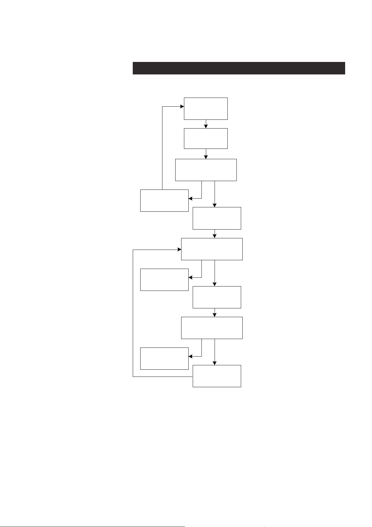
LSA switching logic
Link gets up
Link gets up
Initial
state
Link fails
LSA delay time
Link doesn't
get up
LSA hold time
LSA control is kept activated
(Switch position: Com - port B)
Normal state
(Switch position: Com - port A)
User definable time
(Waiting time in seconds before
the switch operates after first
detected Link Loss Alarm)
LSA control activated
(Switch position: Com - port B)
User definable time
(Waiting time in seconds to
ensure that optical connection
has been established successfully)
Link gets up
Link doesn't
get up
LSA hold time
LSA control is kept de activated
(Switch position: Com - port A)
Link doesn't
get up
LSA control is de-activated
(Switch position: Com - port A)
User definable time
(Waiting time in seconds to
ensure that optical connection
has been established successfully)
LSA control is activated
(Switch position: Com - port B)
To return the switch back to the initial state, use CLI with a command
lsareset to reset the LSA.
4 Optical switch user manual rev001
Page 7
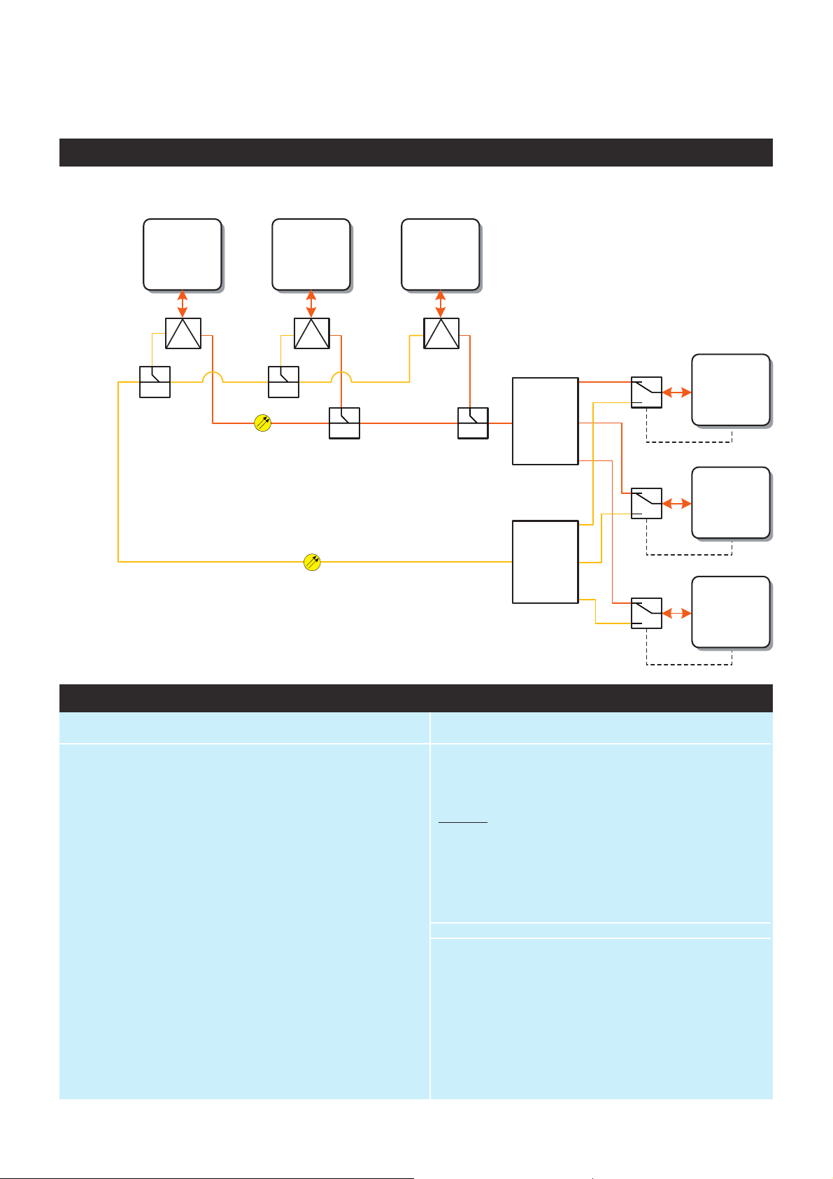
Application example
CEV
Tx
ch11
Add/drops
Optical
splitters
Primary link
Secondary link
CEV
Tx
ch12
CEV
Tx
ch13
Combiner
Combiner
Optical
Switches
LSA
LSA
LSA
CEV
Rx
ch11
CEV
Rx
ch12
CEV
Rx
ch13
Technical specifi cations
Optical
Wavelenght range 1310 ±50 and 1460...1620 nm
Insertion loss 1.0 dB max
Return loss 60 dB
Switching type 1x2 non-latching
Switching time 8 ms
Cross-talk 60 dB min
Switching speed 10 Hz max
Durability 10 million cycles min
Optical power handling 1000 mW
General
Supply voltage 12 V / 30 mA
Power consumption (max) 400 mW
Dimensions (H x W x D) 3U • 5HP • 190 mm without CMA
Weight 0.5 kg
Connectors
External control 2 -pin screw terminal
For CEV and data troughput 2 x RJ-45
Optical 3 x SC/APC
Operating temperature -34...+74 °C
Storage temperature -40...+85 °C
Humidity 0...95 % non condensing
Notes
Typical values unless otherwise stated
Optical switch user manual rev001 5
Page 8
Copyright acknowledgements
Information in this document is subject to change without notice and does not
represent a commitment on the part of Teleste Corporation.
Copyright © Teleste Corporation. All Rights Reserved.
No part of this document may be reproduced, transmitted, stored in a
retrieval system, or translated into any other language without the express
permission of Teleste Corporation.
Teleste Corporation
Video Networks
P.O. Box 323
FIN-20101 Turku
FINLAND
www.teleste.com
WEEE directive
Directive 2002/96/EC of the European Parliament and of the Council on waste
electrical and electronic equipment (WEEE) obliges that producers appropriately
mark electrical and electronic equipment with the symbol indicating separate
collection. This obligation applies to the equipment put on the market in EU after
13 August 2005.
Teleste devices which belong to the scope of the directive have been marked
with the separate collection symbol shown below. The marking is according to
the standard EN 50419. The symbol indicates that the device has to be collected
and treated separately from unsorted municipal waste.
User manual revision history note:
The latest version is always available in pdf-format on our web site:
www.teleste.com
 Loading...